

Page 1
R
INSTRUCTIONS
ADJUSTABLE PORT VALVES
These instructions are intended for use only by experienced, qualified combustion start-up
personnel.
Adjustment of this equipment and its component s, by unqualified personnel, can r esult in fire,
explosion, severe personal injury, or even death.
Table Of Contents
Subject
A. General Information ……………………………………………………….…..….……. 2
B. Receiving and Inspection ………………………………………….…….…...…….….. 2
C. Capacities ………….……………………………………………………………………. 3
D. Dimensions …………….………………………………………………………………... 4
E. Installation ………….……………………………………………………………….…… 5
F. Operation…………………………………………………………………………………. 6
G. Maintenance …………………………………………………………………..………… 7
Page
These instructions are int ended to serve as guidelines c overing the ins tallat ion, operation, and mai ntenance of Hauc k equipment . W hile
every attempt has been m ade to ensure completeness, unforeseen or uns pecified applications, details, and variations may preclude
covering every possible conti ngency.
OPERATE ANY EQUIPMENT OR COMPONENT WITH ANY PARTS REMOVED OR ANY PARTS NOT APPROVED BY THE
MANUFACTURER.
sufficiently for t he purchaser's purpose, contac t Hauck Mfg. Co.
HAUCK MANUFACTURING CO.,
Fax: 717-273-9882
2/04
Should further information be required or desired or should particular problems arise which are not covered
WARNING: TO PREVENT THE POSSIBILITY OF SERIOUS BODILY INJURY, DO NOT USE O
P.O. Box 90 Lebanon, PA 17042-0090 717-272-3051
www.hauckburner.com
WARNING
APV-9
Page 2

Page 2
APV-9
This equipment is potentially dangerous with the possibilit y of serious personal injury
and property damage. Hauck Manufacturing Company recommends the use of flame
supervisory equipment and fuel safety shutoff valves. Furthermore, Hauck ur ges rigid
adherence to National Fire Protection Association (NFPA) st andar ds and insur ance
underwriter’s requirements. O per ation and regular preventative maintenance of this
equipment should be perform ed only by properly trained and qualified personnel.
Annual review and upgrading of safety equipment is recommended.
WARNING
A. GENERAL INFORMATION
The Hauck Adjustable Air and Gas Port Valves are a dependable, accurate means of controlling
the flow of air or gas to any variable pressure type of burner or system. Flow control may be
either manual or automatic. T hese valves are easily adjustable and designed to hold the desired
setting in either mode of operation. Each side of the valve is equipped with four drilled and
tapped mounting pads. This facilitates the installation of multiple valve units or an automatic
control system. These units are designed t o be used as efficient control systems, not as shutoff
valves.
B. RECEIVING AND INSPECTION
Upon receipt, check each item on the bill of lading and/or invoice to determine that all
equipment has been r eceived. A caref ul examination of all parts should be made to ascer tain if
there has been any damage in shipment.
If the installation is delayed and the equipment is
stored outside, provide adequate protection as
dictated by climate and period of exposure. Special
care should be given to all motors and bearings, if
applicable, to protect them f r om rain or excessive
moisture.
IMPORTANT
Page 3
Page 3
APV-9
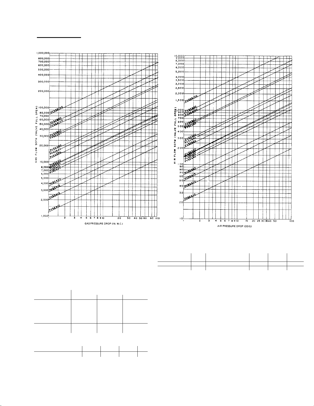
C. CAPACITIES
NATURAL GAS AIR
NOTES:
1. Capacities based on gas @ 0.60 s.g., air @ 1.0 s.g., and
68°F temperature.
2. Static pressure drop measured across full open val ve, i .e.,
pointer at position 10 and adjust i ng screw turned in fully.
3. Maximum inlet pressure is
5 psig
4. Maximum temperature is
for 6" and larger valve size.
15 psig
200°F
up to 4" valve size and
.
Q137
SPECIFIC GRAVITY (GAS Correction Factor C3)
Coke Blast
Gas Oven Natural Gas Furnace Propane Butane
Specific Gravity .40 .59 .60 .61 1.02 1.52 2.01
Multiplier 1.224 1.007 1.000 .992 .767 .628 .547
CORRECTION FACTORS
PRESSURE (GAS OR AIR Correc tion Factor C
Pressure Inlet Pressure (psig)
Drop (psig) 5 10 15
1 1.15 1.29 1.42
2 1.63 1.80 1.95
3 1.95 2.25 2.45
4 2.20 2.50 2.85
5 2.45 2.75 3.00
10 3.70 4.05
15 4.70
TEMPERATURE (GAS OR AIR Correction Factor C2)
Temperature (°F) 68 100 150 200
Multiplier 1.00 1.03 1.07 1.12
)
1
EXAMPLE:
Determine the corrected vol umetric flow rate in standard cubic feet per hour for a
PVS2A20 (2") adjustable port val ve f or propane gas at 100°F having an inlet
pressure of 15 psig and a pressure drop of 5 psig.
Using the equation:
1. From the standard flow curve for Natural Gas (Q137) at 27.7 "w.c. pressure
drop, determine the rated flow:
2. From the Pressure c orrection factor table, determine the pressure correct i on
factor: C
3. From the Temperature correction factor table, det ermine the temperature
correction factor: C
4. From the Specifi c Gravity correction fact or table, determine the spec i fic
gravity correction factor for Propane: C
Then,
= 27,170 scfh of propane gas
= 3.00
1
Q
(corrected) = (3.00) x (1.03) x (0.628) x (14,000)
Q
(corrected) = C1 x C2 x C3 x Q(rated)
Q
(rated) = 14,000 scfh.
= 1.03
2
= 0.628
3
Figure 1. Capacities
Q140
Page 4
Page 4
APV-9
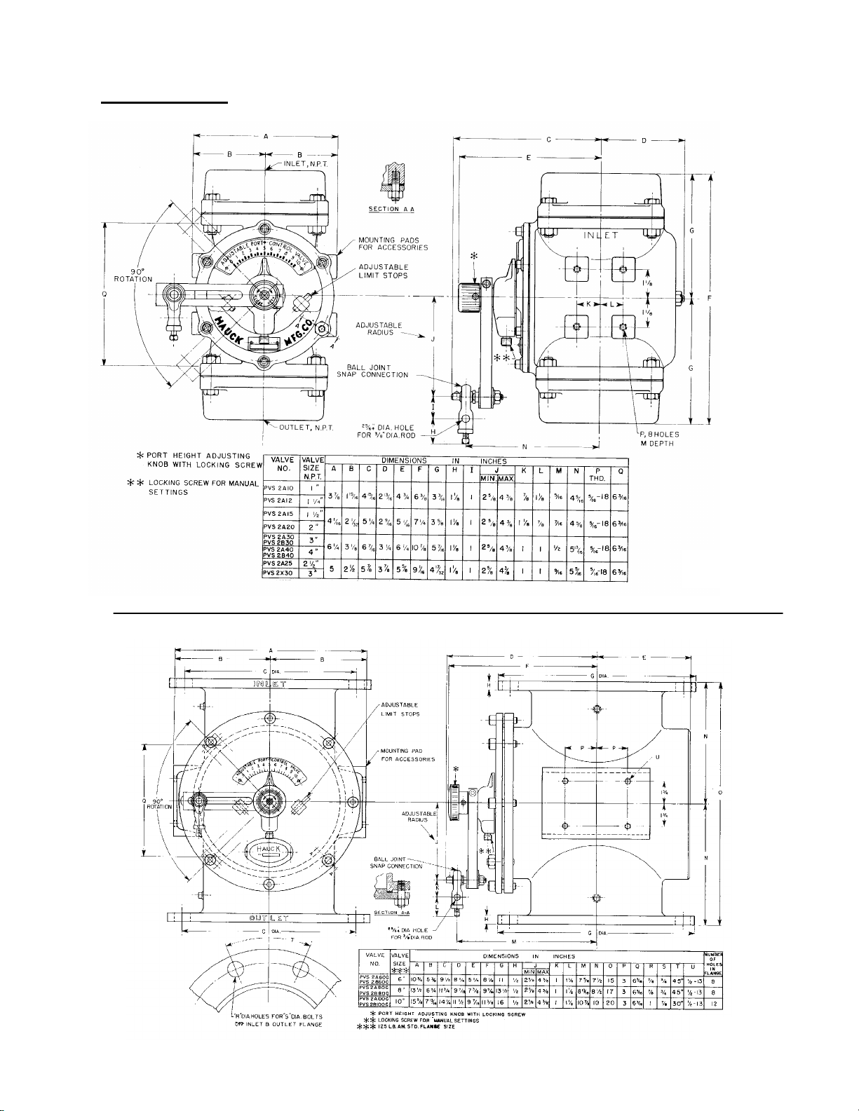
D. DIMENSIONS
GY231
(NOT TO SCALE)
Figure 2. Dimensions
GY229
(NOT TO SCALE)
Page 5
Page 5
APV-9
E. INSTALLATION
1. The port valve can be installed in any position, at any convenient location in the air or gas
line. When inst alling this valve, provide a means for measuring the line pr essure downstream
of the valve. These valves are designed to operate with pressures up to 15 psi g (103 kPa)
for 1" through 4" valve size, and 5 psig (34 kPa) for 6" and larger valve size. The 1" to 4"
valves are designed with female connections threaded for standar d pipe. The 6" and larger
valves have ANSI 125lb flange connections. These valves should not be used when the
temperature exceeds 200°F (93°C). Ensure that all piping both to and from the valve is
properly aligned and supported to prevent undue strain on the valve.
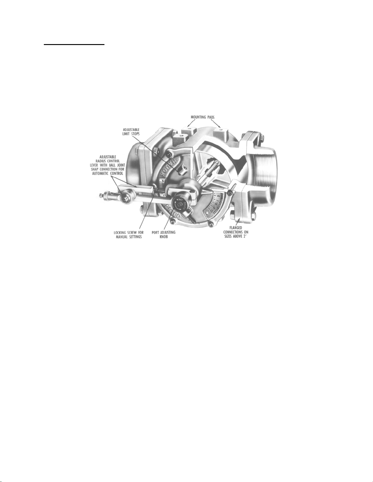
Figure 3. Adjustable Port Valve Cutaway Diagram
2. When an aut om at ic operation is to be used, a control motor should be mount ed to the valve
or some other nearby rigid support. Recomm ended m otor torque requirement for the 1" to 4"
valves is 20 in-lbs (2.3Nm); 40 in-lbs (4.5Nm) for the 6" or larger valves. The valves operating
arm moves in a clockwise direction to open the valve over an arc of about 90° at an adjust -
able radius from 2-5/8" to 4-3/8" (67 to 111mm).
A. Connect the valve lever to the control motor arm by a 3/8" (9.5mm) rod through the snap
connection pin on the valve lever. A setscrew is provided on the snap pin to secure the
rod at the proper point.
B. Loosen the locking screw located on the base of the dial indicator. This will allow easy
movement of the valve pointer.
C. Adjust the two limit stops until they allow movement of the pointer over the entire range of
dial positions.
D. Adjust the length of the control motor arm so that the valve pointer moves through the
desired range on the valve dial. Be sure that the contr ol m otor does not move the valve
lever beyond the stops on the dial as this can damage the valve if sufficient force is
applied.
Page 6
Page 6
APV-9
F. OPERATION
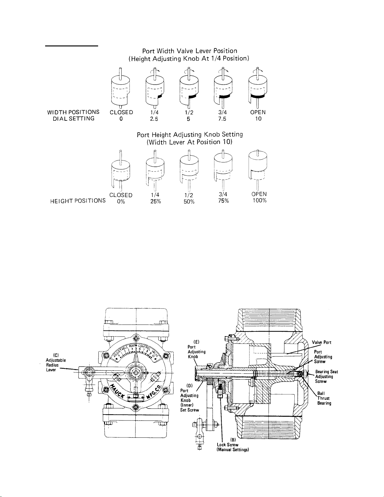
Figure 4. Illustration of Valve Height and Width Adjustments
Manual or automatic control is accomplished by moving the port adjusting k nob and the radius
control lever. The capacity of the air or gas flow is determined by the height and width of the
valve port opening in relation to the valve outlet. The heig ht of the port is cont rolled by the port
adjusting knob. The width of the port is cont rolled by the radius control lever. Rotating this lever
proportionally uncovers the rectangular port in the valve body.
Figure 5. Adjustable Port Valve Diagram
Page 7

Page 7
APV-9
Once installed, adjustm ents of the port adjusting k nob and the r adius control lever ar e achieved
by accomplishing the following:
A. Disconnect t he aut omatic linkage (if present ).
B. Loosen the dial point er locking screw.
C. Rotate the radius control lever to position 10.
D. Loosen the setscrew which holds the port adjusting knob at the proper set ting.
Exercise care since two setscrews exist on the knob. The inner setscrew maintains the
setting while the outer setscrew fastens the k nob to the stem. Only the inner setscrew
should be loosened.
E. Turn the adjusting cont rol knob counterclockwise until the FULLY CLOSED position is
reached.
F. Initiate the flow of air or gas through the line.
G. Rotate the adjusting knob clockwise until the pressure gauge(s) indicates the maximum
Pressure required. The pr essur e needed will vary depending on the burner , the piping,
and the application. The table given below gives the approximate number of turns from
FULL CLOSED TO FULL OPEN.
I. Connect the linkage for automatic control.
The vibration-proof locking scr ew, located at the base of t he dial pointer , should be used t o lock
any manual setting of the valve pointer. W hen operating automatically, this locking screw must
be loosened to facilitate the movement of the pointer.
Hauck adjustable port valves are designed for efficient f low control; they are not intended for
use as complete shut-off valves.
G. MAINTENANCE
All port valves are designed and constructed for maintenance free operation. Under normal
usage no service should be necessary.
If should become necessary to clean the valve, the entire port assembly can be easily removed,
in one piece, by accomplishing the following:
PVS 2A100 & PVS 2B100 66
H. Tighten the inner setscrew on the port adjust ing knob.
A. Disconnect t he aut omatic linkage (if present ).
B. Loosen and remove all of the screws, and the nut on the guide bolt, holding the dial
plate cover to the valve body.
C. Extract the entire port assembly.
D. Wipe the port cylinder clean of any part icles or residue. If scarring of the cylinder has
occurred, use an emery cloth to restore a smooth sur face.
VALVE MODEL FULL CLOSED TO FULL OPEN
PVS 2A10 & PVS 2A12 18
PVS 2A15 & PVS 2A20 22
PVS 2A30 & PVS 2B40 29
PVS 2A60 & PVS 2B60 43
PVS 2A 80 & PVS 2B80 48
APPROXIMATE NO. OF TURNS FROM
Page 8

Page 8
APV-9
MAINTENANCE (Continued)
E. Lubricate the port cylinder with Molykote or some other suitable high t emperatur e, non-
gumming lubricant.
F. Reinsert the port assembly. Use the location of the guide bolt to ensure proper
alignment. Ensure that the stem is properly seated in the bushing at the back of the
valve body.
G. Replace and properly seat the dial plate cover gaskets.
H. Replace and tighten all of the screws in the dial plate cover.
I. Move the radius control lever through its f ull range of movement. If the movement is
either binding or too free moving, adjust the bearing seat adjusting setscrew on the
valve back by accomplishing the following:
a. Loosen the locknut which secures the setscrew.
b. Slowly tighten the setscrew (clockwise rotation) until there is resistance to the
movement of the lever.
c. Rotate the setscrew 1/8 to 1/4 turn in a counterclockwise direction.
d. Tighten the lock nut.
J. Reconnect the automatic linkag e ( if used).
 Loading...