

Page 1
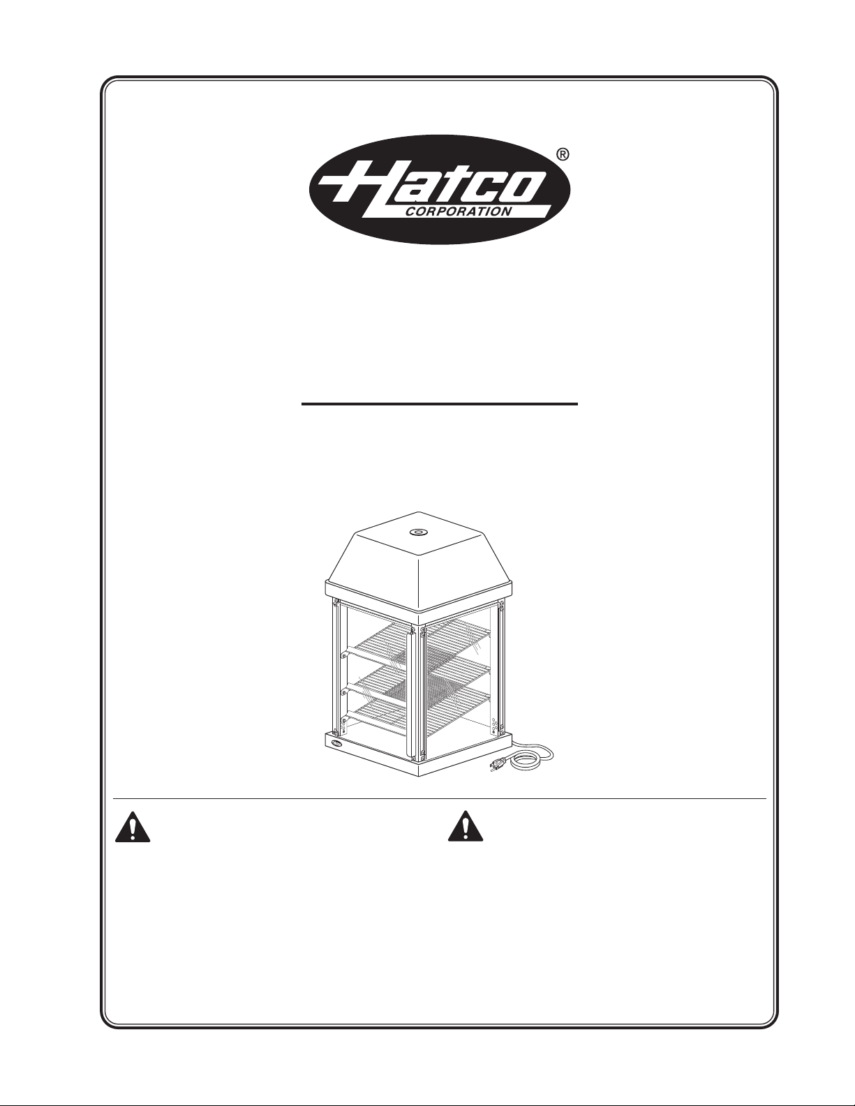
Mini Display Warmer
MDW Series
Installation and Operating Manual
I&W #07.05.176.00
Do not operate this equipment unless
you have read and understood the
contents of this manual! Failure to follow
the instructions contained in this manual
may result in serious injury or death. This
manual contains important safety
information concerning the maintenance,
use, and operation of this product. If
you’re unable to understand the contents
of this manual, please bring it to the
attention of your supervisor. Keep this
manual in a safe location for future
reference.
No opere este equipo al menos que haya
leído y comprendido el contenido de este
manual! Cualquier falla en el seguimiento
de las instrucciones contenidas en este
manual puede resultar en un serio lesión
o muerte. Este manual contiene
importante información sobre seguridad
concerniente al mantenimiento, uso y
operación de este producto. Si usted no
puede entender el contenido de este
manual por favor pregunte a su
supervisor. Almacenar este manual en
una localización segura para la referencia
futura.
© 2008 Hatco Corporation
Page 2
CONTENTS
NOTICE
CAUTION
WARNING
Important Owner Information...............................i
Introduction ...........................................................i
Important Safety Information ..............................1
Model Description................................................2
Model Designation ...............................................2
Specifications.......................................................3
Plug Configurations .........................................3
Electrical Rating Chart.....................................3
Dimensions......................................................3
Installation ............................................................4
General............................................................4
Reversible Access Door ..................................5
Configurable Access Door...............................5
Operation ..............................................................6
Maintenance .........................................................7
Options..................................................................9
Troubleshooting.................................................10
Hatco Limited Warranty.....................................11
Authorized Parts Distributors ...........Back Cover
IMPORTANT OWNER INFORMATION
Record the model number, serial number (located on
the side of the unit), voltage and purchase date of
your Mini Display Warmer in the spaces below.
Please have this information available when calling
Hatco for service assistance.
Model No. ________________________________
Serial No. ________________________________
Voltage __________________________________
Date of Purchase __________________________
Business 8:00 a.m. to 5:00 p.m.
Hours: Central Standard Time
Telephone: (800) 558-0607; (414) 671-6350
Fax: (800) 690-2966 (Parts and Service)
General............................................................6
General............................................................7
Cleaning...........................................................7
Display Light Bulb Replacement .....................8
Installing a Graphic Image...............................9
Relocating the Graphic Panel..........................9
(Summer Hours: June to September –
8:00 a.m. to 5:00 p.m. C.S.T.
Monday through Thursday
8:00 a.m. to 2:30 p.m. C.S.T. Friday)
(414) 671-3976 (International)
24 Hour 7 Day Parts and Service
Assistance available in the
United States and Canada
by calling (800) 558-0607.
INTRODUCTION
The Hatco Mini Display Warmer is designed to hold
prepared foods for prolonged periods of time while
maintaining that “just-made” quality. Mini Display
Warmer cabinets provide the best environment for
products like sandwiches, cookies, pretzels, muffins,
and desserts by regulating the air temperature.
The Mini Display Warmer air flow pattern is designed
to maintain consistent cabinet temperature. The heat
sources create a “blanket” effect around the food.
The air flow rate enables the cabinet to rapidly
recover temperature after opening and closing the
door. Configurable access doors and magnetic
adjustable shelves make the Hatco Mini Display
Warmer perfect for any food service application.
The Mini Display Warmer is a product of extensive
research and field testing. The materials used were
selected for maximum durability, attractive
appearance, and optimum performance. Every unit
is inspected and tested thoroughly prior to shipment.
This manual provides installation, safety, and
operating information for the Mini Display Warmer.
Additional information can be found by visiting our
web site at www.hatcocorp.com.
Hatco recommends all installation, operating, and
safety information appearing in this manual be read
prior to installation or operation of the Hatco Mini
Display Warmer.
Safety information that appears in this manual is
identified by the following signal word panels:
WARNING indicates a hazardous situation
which, if not avoided, could result in death or
serious injury.
CAUTION indicates a hazardous situation which,
if not avoided, could result in minor or moderate
injury.
NOTICE is used to address practices not related
to personal injury.
i
Form No. MDWM-0608
Page 3

IMPORTANT SAFETY INFORMATION
WARNING
NOTICE
CAUTION
WARNING
Read the following important safety information to avoid serious injury or death and to
avoid damage to equipment or property.
ELECTRIC SHOCK HAZARD:
• Plug unit into a properly grounded electrical
outlet of the correct voltage, size, and plug
configuration. If the plug and receptacle do
not match, contact a qualified electrician to
determine and install the proper voltage and
size electrical outlet.
• Turn the power switch OFF, unplug the power
cord, and allow the unit to cool before
performing any maintenance or cleaning.
• DO NOT submerge or saturate with water.
Unit is not waterproof. Do not operate if unit
has been submerged or saturated with water.
• Unit is not weatherproof. Locate the unit
indoors where the ambient air temperature is
a minimum of 70°F (21°C) and a maximum of
85°F (29°C).
• Do not steam clean or use excessive water on
the unit.
• Do not pull unit by power cord.
• Discontinue use if power cord is frayed or
worn.
• Do not attempt to repair or replace a damaged
power cord. The cord must be replaced by
Hatco, an Authorized Hatco Service Agent, or
a person with similar qualifications.
• Use only Genuine Hatco Replacement Parts
when service is required. Failure to use
Genuine Hatco Replacement Parts will void
all warranties and may subject operators of
the equipment to hazardous electrical
voltage, resulting in electrical shock or burn.
Genuine Hatco Replacement Parts are
specified to operate safely in the
environments in which they are used. Some
aftermarket or generic replacement parts do
not have the characteristics that will allow
them to operate safely in Hatco equipment.
This unit has no “user-serviceable” parts. If
service is required on this unit, contact an
Authorized Hatco Service Agent or contact the
Hatco Service Department at 800-558-0607 or
414-671-6350; fax 800-690-2966; or International
fax 414-671-3976.
BURN HAZARD: Some exterior surfaces on the
unit will get hot. Use caution when touching
these areas.
Locate the unit at the proper counter height in an
area that is convenient for use. The location
should be level to prevent the unit or its contents
from falling accidentally and strong enough to
support the weight of the unit and contents.
Do not lay unit on the side with the control panel
or damage to the unit could occur.
Use non-abrasive cleaners only. Abrasive
cleaners could scratch the finish of the unit,
marring its appearance and making it
susceptible to soil accumulation.
FIRE HAZARD: Locate the unit a minimum of
1″ (25 mm) from combustible walls and
materials. If safe distances are not maintained,
combustion or discoloration could occur.
Use only light bulbs that meet or exceed
(National Sanitation Foundation (NSF) standards
and are specifically designed for food holding
areas. Breakage of light bulbs not specially
coated could result in personal injury and/or
food contamination.
Form No. MDWM-0608
1
Page 4
MODEL DESCRIPTION
M D W - 1 X
Mini
Warmer
Display
Quantity Of Doors
No Revolving Display
All Models
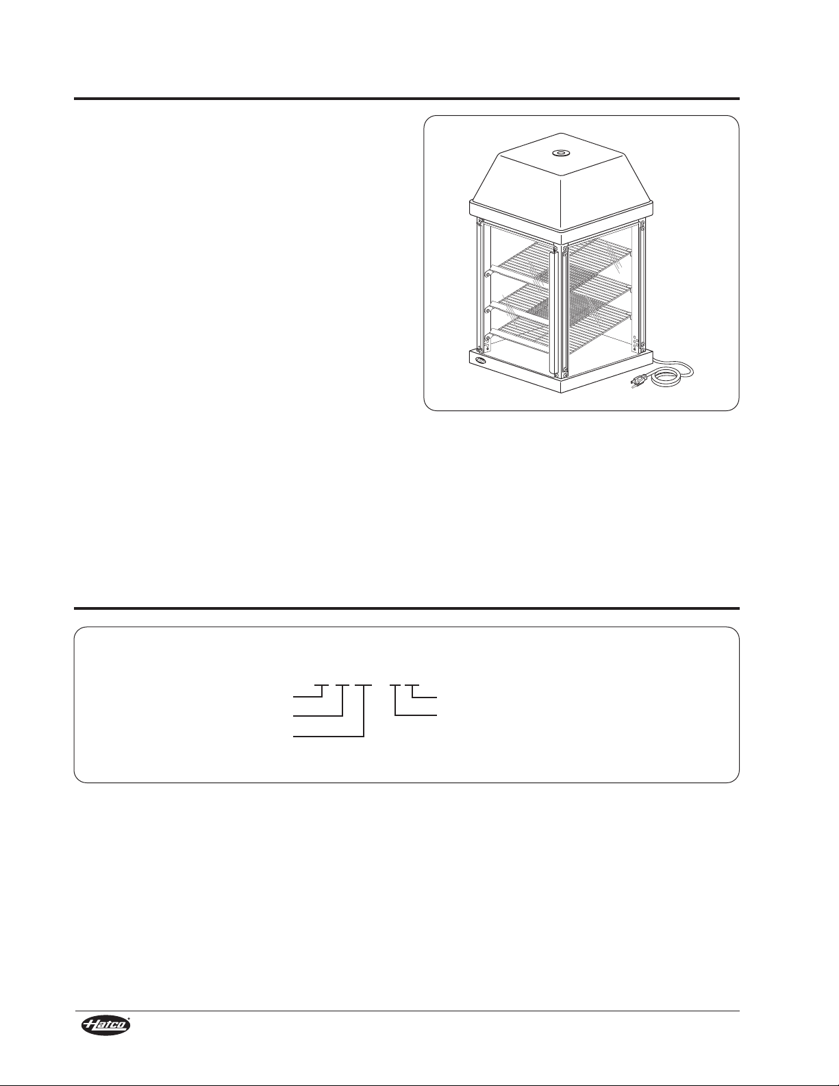
Mini Display Warmers are powder-coated, painted
steel and feature tempered glass sides. The access
door(s) can be hinged left or right and are
configurable for any side to allow “pass-through”
from the side or back to the service area. The
cabinet interior top and bottom are made of easy-toclean stainless steel. The unit’s dry heat system is
suitable for all boxed or wrapped food products as
well as unwrapped muffins, turnovers, and desserts.
Three magnetically adjustable shelves for horizontal
or slanted displays provide flexibility for a variety of
product choices. Shelf height is also adjustable to
accommodate a variety of food package sizes. The
unit has incandescent lighting to heighten product
awareness.
The Hatco Mini Display Warmer holds and serves
products at temperatures up to 180°F (82°C).
Perfect for convenience stores, restaurants,
recreational facilities, theme parks, and anywhere
there is limited counterspace.
Available in six Designer colors: Warm Red, Black,
Gray Granite, White Granite, Navy Blue and Hunter
Green.
Figure 1. Model MDW-2X
NOTE: The top cover of the Mini Display Warmer is
always black.
MODEL DESIGNATION
Figure 2. Model Designation
2
Form No. MDWM-0608
Page 5
SPECIFICATIONS
NEMA 5-15P
WARNING
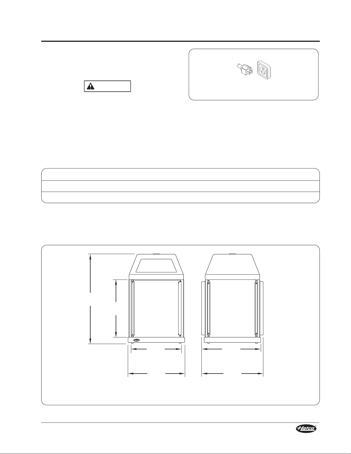
15-3/4″
(400 mm)
Square Base
17-1/4″
(438 mm)
2 Doors
16-1/2″
(419 mm)
1 Door
14-1/8″
(359 mm)
Square Footprint
25-1/8″
(638 mm)
16″
(406 mm)
Front View Side View
Plug Configuration
Units are supplied from the factory with a 6'
(1829 mm) electrical cord and NEMA 5-15P plug
installed (see Figure 3).
ELECTRIC SHOCK HAZARD: Plug unit into a
properly grounded electrical outlet of the correct
voltage, size, and plug configuration. If the plug
and receptacle do not match, contact a qualified
electrician to determine and install the proper
NOTE: Receptacle not supplied by Hatco.
voltage and size electrical outlet.
Electrical Rating Chart
Model Voltage Watts Amps Plug Configuration Shipping Weight
MDW-1X 120 470 3.9 NEMA 5-15P 46 lbs (21 kg)
MDW-2X 120 470 3.9 NEMA 5-15P 48 lbs (22 kg)
Figure 3. Plug Configuration
Dimensions
Figure 4. Dimensions
Form No. MDWM-0608
3
Page 6

NOTICE
CAUTION
WARNING
Product Stop
Magnet
Shelves may be
inserted horizontally
or inclined.
INSTALLATION
General
The Mini Display Warmer is shipped with most
components installed and ready for operation. The
following installation instructions must be performed
before plugging in and operating the unit.
FIRE HAZARD: Locate the unit a minimum of 1″
(25 mm) from combustible walls and materials. If
safe distances are not maintained, combustion
or discoloration could occur.
Unit is not weatherproof. Locate the unit indoors
where the ambient air temperature is a minimum
of 70°F (21°C) and a maximum of 85°F (29°C).
Locate the unit at the proper counter height in an
area that is convenient for use. The location
should be level to prevent the unit or its contents
from falling accidentally and strong enough to
support the weight of the unit and contents.
Do not lay unit on the side with the control panel
or damage to the unit could occur.
1. Remove unit from box.
2. Remove the information packet.
NOTE: To prevent delay in obtaining warranty
coverage, fill out and mail in the warranty
card to Hatco.
3. Remove tape and protective film from all
surfaces of unit.
4. The stainless steel floor in all units is protected
during shipping with a sheet of corrugated
cardboard. This protection must be removed
prior to cabinet operation.
5. The shelves have packing material and
cardboard attached for protection during
shipping. This protection must be removed prior
to cabinet operation.
6. Position the shelves at adequate heights to
accommodate your product. The shelves may
be inserted horizontally or inclined with the
product stops toward the service area access
(see Figure 5).
7. If the unit is equipped with an optional
Merchandising Display Cover, see the
Accessories section for installation instructions.
NOTE: The unit must be transported in the upright
position. If laid on its side, all glass surfaces
must be secured with tape.
Figure 5. Shelves
4
Form No. MDWM-0608
Page 7

INSTALLATION
Attach fixed glass panels
using inner holes.
Attach reversible accessdoors
using outer holes.
Bracket
Hinge/Pivot Pin
Reversible Access Door
Any door may be changed from hinged left to hinged
right.
1. While holding the door securely, remove the
screw attaching the top left hinge/pivot pin to the
cabinet.
2. Carefully lift the door off of the bottom
hinge/pivot pin. Also remove the nylon washer
and save.
3. Rotate the removed hinge and attach (with the
pivot pin facing up) using the removed screw to
the bottom-most outer hole on the right-hand
side of the cabinet (see Figure 6).
4. Remove the screw attaching the bottom left
hinge/pivot pin to the cabinet.
5. Rotate the door 180° and install the nylon
washer and the door onto the newly attached
bottom right hinge/pivot pin.
6. Rotate the removed hinge (the pivot pin now
facing down) and insert it into the top of the door.
7. Line up the hinge’s hole with the top-most hole
in the cabinet and attach with the removed
screw.
Configurable Access Door
Any door may be exchanged with a fixed glass panel
to suit the installation.
1. While holding the door securely, remove the screw
attaching the top hinge/pivot pin to the cabinet.
2. Carefully lift the door off of the bottom
hinge/pivot pin. Also remove the nylon washer
and save.
3. Remove the screw attaching the bottom
hinge/pivot pin to the cabinet. Keep the nylon
washer and hardware.
4. While holding the fixed glass panel securely,
remove the four screws attaching the two
brackets to the cabinet.
5. Carefully move the fixed glass panel to the side
of the unit from which the door was removed.
6. Line up the holes in one bracket with the inner
holes in the cabinet and attach with the screws
(see Figure 6). Repeat on the opposite side of
the fixed glass panel.
7. On the side of the unit from which the fixed glass
panel was removed, line up the hole in the
hinge/pivot pin (with the pivot pin facing up) with
the bottom-most hole in the unit and attach with
a removed screw.
8. Install the nylon washer and the door onto the
newly attached bottom hinge/pivot pin.
9. Insert the remaining hinge/pivot pin (the pivot pin
facing down) into the top of the door.
10. Line up the hinge’s hole with the top-most hole
in the cabinet and attach with the other removed
screw.
Form No. MDWM-0608
Figure 6. Reversible Access Door and Fixed Glass Panel
5
Page 8

OPERATION
Interior
Thermometer
Power Switch
Temperature
Control
CAUTION
WARNING
General
Use the following procedure to turn on and operate
the Hatco Mini Display Warmer.
Read all safety messages in the IMPORTANT
SAFETY INFORMATION section before operating
this equipment.
1. Plug unit into an electrical outlet of the correct
voltage, size and plug configuration. See the
SPECIFICATIONS section for details.
2. Move the Power switch on the control panel to
the On position (see Figure 7).
3. Set the Temperature Control to the desired level
between MIN and MAX.
BURN HAZARD: Some exterior surfaces on the
unit will get hot. Use caution when touching
these areas.
4. Allow 30 minutes to preheat, check the interior
thermometer and adjust the Temperature
Control if necessary.
NOTE: Temperature settings may vary depending
upon product make-up and consistency. The
interior thermometer displays temperature
inside the cabinet, not the food product
temperature.
Figure 7. Control Panel
6
Form No. MDWM-0608
Page 9

MAINTENANCE
Screw
Bracket
NOTICE
WARNING
General
The Hatco Mini Display Warmer is designed for
maximum durability and performance, with minimum
maintenance.
ELECTRIC SHOCK HAZARD:
• Turn the power switch OFF, unplug the power
cord, and allow the unit to cool before
performing any maintenance or cleaning.
• DO NOT submerge or saturate with water.
Unit is not waterproof. Do not operate if unit
has been submerged or saturated with water.
• Do not steam clean or use excessive water on
the unit.
This unit has no “user-serviceable” parts. If
service is required on this unit, contact an
Authorized Hatco Service Agent or contact the
Hatco Service Department at 800-558-0607 or
414-671-6350; fax 800-690-2966; or International
fax 414-671-3976.
Cleaning
Removing Glass for Cleaning
1. While holding the fixed glass panel securely,
remove the four screws attaching the two
brackets to the cabinet. Keep hardware.
2. Carefully lift the fixed glass panel off to clean.
Installing Glass
1. Return the fixed glass panel to the side of the
cabinet.
2. Line up the holes in one bracket with the inner
holes in the cabinet and attach with two screws.
Repeat on the opposite side of the panel.
Use non-abrasive cleaners only. Abrasive
cleaners could scratch the finish of the unit,
marring its appearance and making it
susceptible to soil accumulation.
To preserve the finish of the Mini Display Warmer
cabinet, it is recommended that the exterior and
interior surfaces be wiped daily with a damp cloth.
Shelves should be removed and washed. Stubborn
stains may be removed with a good stainless steel
cleaner or a non-abrasive cleaner. Hard to reach
areas should be cleaned with a small brush and mild
soap.
Clean the glass sides using a common glass
cleaner. In almost all cases, glass panels should be
cleaned while remaining in the unit. Only for difficult
or hard to clean stains is removal of the fixed glass
panels suggested.
Figure 8. Glass Panel Removal
Form No. MDWM-0608
7
Page 10

MAINTENANCE
Threaded Cap
Top Cover
Hood Filler Panel
Light Bulb
WARNING
Display Light Bulb Replacement
The display light is an incandescent bulb that
illuminates the warming area. This bulb has a
special coating to guard against injury and food
contamination in the event of breakage.
Use only light bulbs that meet or exceed
(National Sanitation Foundation (NSF) standards
and are specifically designed for food holding
areas. Breakage of light bulbs not specially
coated could result in personal injury and/or
food contamination.
Use only Genuine Hatco Replacement Parts
when service is required. Failure to use Genuine
Hatco Replacement Parts will void all warranties
and may subject operators of the equipment to
hazardous electrical voltage, resulting in
electrical shock or burn. Genuine Hatco
Replacement Parts are specified to operate
safely in the environments in which they are
used. Some aftermarket or generic replacement
parts do not have the characteristics that will
allow them to operate safely in Hatco equipment.
1. Disconnect the power supply and wait until the
unit has cooled.
2. Unscrew and remove the threaded cap from the
the top cover (see Figure 9).
3. Remove the top cover from the cabinet (see
Figure 9).
4. Remove one hood filler panel. (Two screws
need to be removed to remove the hood filler
panel.)
5. Unscrew the bulb from the unit and replace it
with a new specially coated incandescent bulb
(display light bulbs have a threaded base).
Hatco shatter-resistant bulbs meet NSF
standards for food holding and display areas.
When replacing the light bulb, use Hatco part
number 02.30.043.00.
6. Reinstall the hood filler panel.
7. Securely place the top cover back onto the
cabinet.
8. Reinstall the threaded cap to secure the top
cover.
Figure 9. Bulb Replacement
8
Form No. MDWM-0608
Page 11

OPTIONS
Hood Filler Panel
Hood Filler Panel
Top Cover
Frame
Top Cover
Top Cover
Frame
Threaded Cap
Graphic Panel
Tab
Graphic Decal
Notch
Installing A Graphic Image
Use the following procedure to apply a graphic
image to the plexiglass graphic panel in the top
cover of the unit.
1. Disconnect the power supply and wait until the
unit has cooled.
2. Unscrew and remove the threaded cap from the
top cover (see Figure 10).
3. Remove the top cover.
4. Remove the graphic panel from the top cover
frame.
5. Apply the graphic image:
• If the graphic image is a decal, peel off the
backing paper from the graphic decal and
apply the decal to the graphic panel.
• If the graphic image is non-adhesive, trim the
image to the shape of the graphic panel leaving
no more than an 1/8″ gap between the image
and the edge of the panel. Then, tape the
image to the inside face of the graphic panel.
Make sure to tape around the entire edge of
the image so that it does not hang loose.
6. Install the graphic panel with the tabs on the
panel resting in the corner notches of the top
cover frame (see Figure 10).
7. Securely place the cover back onto the cabinet.
Make sure the cut-out in the top cover is over the
graphic panel.
8. Reinstall the threaded cap to secure the top cover.
Relocating the Graphic Panel
Use the following procedure to change the location
of the graphic panel at the top of the unit. The
graphic panel can be installed into any of the four
openings of the top cover frame.
1. Disconnect the power supply and wait until the
unit has cooled.
2. Unscrew and remove the threaded cap from the
top cover (see Figure 10).
3. Remove the top cover.
4. Remove the graphic panel from its existing
location in the top cover frame.
5. Remove the hood filler panel from the side
where the graphic panel needs to be installed.
(Two screws need to be removed to remove the
hood filler panel.)
6. Install the hood filler panel onto the side where
the graphic panel was originally located. Make
sure the top lip of the hood filler panel fits over
the edge of the top cover frame and the two
screws are installed (see Figure 10).
7. Install the graphic panel into the new position
with the tabs on the graphic panel resting in the
corner notches of the top cover frame.
8. Securely place the top cover back onto the
cabinet. Make sure the cut-out in the top cover is
over the graphic panel.
9. Reinstall the threaded cap to secure the top cover.
Form No. MDWM-0608
Figure 10. Merchandising Display Sign
9
Page 12

TROUBLESHOOTING
WARNING
WARNING
This unit must be serviced by qualified
personnel only. Service by unqualified personnel
may lead to electric shock or burn.
ELECTRIC SHOCK HAZARD: Turn the power
switch OFF, unplug the power cord, and allow
the unit to cool before performing any
maintenance or cleaning.
Symptom Probable Cause Corrective Action
Light bulb not working. Light bulb defective.
Power turned OFF.
Food cavity not hot enough. Temperature control set too low.
Heating element(s) not working.
Temperature control not working
properly.
Air circulating fan not working
properly.
Food cavity too hot. Temperature control set too high.
Temperature control not working
properly.
Replace light bulb.
Turn unit ON.
Adjust temperature control to a
higher setting.
Contact Authorized Service Agent
or Hatco for assistance.
Contact Authorized Service Agent
or Hatco for assistance.
Contact Authorized Service Agent
or Hatco for assistance.
Adjust temperature control to a
lower setting.
Contact Authorized Service Agent
or Hatco for assistance.
No heat, but light works. Temperature control set too low.
Heating element(s) not working.
Temperature control not working
properly.
No heat and no light. Unit turned OFF.
Circuit breaker tripped.
Adjust temperature control to a
higher setting.
Contact Authorized Service Agent
or Hatco for assistance.
Contact Authorized Service Agent
or Hatco for assistance.
Turn unit ON.
Reset circuit breaker. If circuit
breaker continues to trip, contact
Authorized Service Agent or
Hatco for assistance.
10
Form No. MDWM-0608
Page 13

HATCO LIMITED WARRANTY
1. PRODUCT WARRANTY
Hatco warrants the products that it manufactures
(the “Products”) to be free from defects in materials
and workmanship, under normal use and service, for
a period of one (1) year from the date of purchase
when installed and maintained in accordance with
Hatco’s written instructions or 18 months from the
date of shipment from Hatco. Buyer must establish
the Product’s purchase date by returning Hatco’s
Warranty Registration Card or by other means
satisfactory to Hatco in its sole discretion.
Hatco warrants the following Product components to
be free from defects in materials and workmanship
from the date of purchase (subject to the foregoing
conditions) for the period(s) of time and on the
conditions listed below:
a) One (1) Year Parts and Labor PLUS One
(1) Additional Year Parts-Only Warranty:
Conveyor Toaster Elements (metal sheathed)
Drawer Warmer Elements (metal sheathed)
Drawer Warmer Drawer Rollers and Slides
Food Warmer Elements (metal sheathed)
Display Warmer Elements (metal sheathed air
heating)
Holding Cabinet Elements (metal sheathed air
heating)
Built-In Heated Well Elements
(metal sheathed)
b) One (1) Year Parts and Labor PLUS Four
(4) Years Parts-Only Warranty on
pro-rated terms that Hatco will explain
at Buyer’s request:
3CS and FR Tanks
c) One (1) Year Parts and Labor PLUS Nine
(9) Years Parts-Only Warranty on:
Electric Booster Heater Tanks
Gas Booster Heater Tanks
THE FOREGOING WARRANTIES ARE
EXCLUSIVE AND IN LIEU OF ANY OTHER
WARRANTY, EXPRESSED OR IMPLIED,
INCLUDING BUT NOT LIMITED TO ANY IMPLIED
WARRANTY OF MERCHANTABILITY OR FITNESS
FOR A PARTICULAR PURPOSE OR PATENT OR
OTHER INTELLECTUAL PROPERTY RIGHT
INFRINGEMENT. Without limiting the generality of
the foregoing, SUCH WARRANTIES DO NOT
COVER: Coated incandescent light bulbs, fluorescent
lights, decorative heat lamp bulbs, coated halogen light
bulbs, halogen heat lamp bulbs, heated glass shelves,
glass components, Product failure in booster tank, fin
tube heat exchanger, or other water heating
equipment caused by liming, sediment buildup,
chemical attack or freezing, Product misuse, tampering
or misapplication, improper installation, or application of
improper voltage.
2. LIMITATION OF REMEDIES AND DAMAGES
Hatco’s liability and Buyer’s exclusive remedy
hereunder will be limited solely, at Hatco’s option, to
repair or replacement by a Hatco-authorized service
agency (other than where Buyer is located outside of
the United States, Canada, United Kingdom or
Australia in which case Hatco’s liability and Buyer’s
exclusive remedy hereunder will be limited solely to
replacement of part under warranty) with respect to
any claim made within the applicable warranty
period referred to above. Hatco reserves the right to
accept or reject any such claim in whole or in part.
Hatco will not accept the return of any Product
without prior written approval from Hatco, and all
such approved returns shall be made at Buyer’s sole
expense. HATCO WILL NOT BE LIABLE, UNDER
ANY CIRCUMSTANCES, FOR CONSEQUENTIAL
OR INCIDENTAL DAMAGES, INCLUDING BUT
NOT LIMITED TO LABOR COSTS OR LOST
PROFITS RESULTING FROM THE USE OF OR
INABILITY TO USE THE PRODUCTS OR FROM
THE PRODUCTS BEING INCORPORATED IN OR
BECOMING A COMPONENT OF ANY OTHER
PRODUCT OR GOODS.
Form No. MDWM-0608
11
Page 14

HATCO CORPORATION
P.O. Box 340500
Milwaukee, WI 53234-0500 U.S.A.
(800) 558-0607 (414) 671-6350
Parts and Service Fax (800) 690-2966
International Fax (414) 671-3976
www.hatcocorp.com
HATCO AUTHORIZED PARTS DISTRIBUTORS
ALABAMA
Jones McLeod Appl. Svc.
Birmingham 205-251-0159
ARIZONA
Auth. Comm. Food Equip.
Phoenix 602-234-2443
Byassee Equipment Co.
Phoenix 602-252-0402
CALIFORNIA
Industrial Electric
Commercial Parts & Service, Inc.
Huntington Beach 714-379-7100
Chapman Appl. Service
San Diego 619-298-7106
P & D Appliance
Commercial Parts & Service, Inc.
S. San Francisco 650-635-1900
COLORADO
Hawkins Commercial Appliance
Englewood 303-781-5548
FLORIDA
Whaley Foodservice Repair
Jacksonville 904-725-7800
Nass Service Co., Inc.
Orlando 407-425-2681
B.G.S.I.
Pompano Beach 954-971-0456
Comm. Appliance Service
Tampa 813-663-0313
GEORGIA
TWC Services
Smyrna 770-438-9797
Heritage Service Group
Norcross 866-388-9837
Southeastern Rest. Svc.
Norcross 770-446-6177
HAWAII
Burney’s Comm. Service, Inc.
Honolulu 808-848-1466
Food Equip Parts & Service
Honolulu 808-847-4871
ILLINOIS
Parts Town
Lombard 708-865-7278
Eichenauer Elec. Service
Decatur 217-429-4229
Midwest Elec. Appl. Service
Elmhurst 630-279-8000
Cone’s Repair Service
Moline 309-797-5323
INDIANA
GCS Service
Indianapolis 317-545-9655
IOWA
Electric Motor Service Co.
Davenport 319-323-1823
Goodwin Tucker Group
Des Moines 515-262-9308
KENTUCKY
Certified Service Center
Lexington 859-254-8854
Certified Service Center
Louisville 502-964-7007
LOUISIANA
Chandlers Parts & Service
Baton Rouge 225-272-6620
MARYLAND
Electric Motor Service
Baltimore 410-467-8080
GCS Service
Silver Spring 301-585-7550
MASSACHUSETTS
Ace Service Co., Inc.
Needham 781-449-4220
MICHIGAN
Commercial Kitchen Service
Bay City 517-893-4561
Bildons Appliance Service
Detroit 248-478-3320
Midwest Food Equip. Service
Grandville 616-261-2000
MINNESOTA
GCS Service
Minneapolis 800-822-2303
MISSOURI
General Parts
Kansas City 816-421-5400
Commercial Kitchen Services
St. Louis 314-890-0700
Kaemmerlen Parts & Service
St. Louis 314-535-2222
NEBRASKA
Anderson Electric
Omaha 402-341-1414
NEVADA
Burney’s Commercial
Las Vegas 702-736-0006
Hi. Tech Commercial Service
N. Las Vegas 702-649-4616
NEW JERSEY
Jay Hill Repair
Fairfield 973-575-9145
Service Plus
Flanders 973-691-6300
NEW YORK
Acme American Repairs, Inc.
Brooklyn 718-456-6544
Alpro Service Co.
Brooklyn 718-386-2515
Appliance Installation
Buffalo 716-884-7425
Northern Parts Dist.
Plattsburgh 518-563-3200
J.B. Brady, Inc.
Syracuse 315-422-9271
NORTH CAROLINA
Authorized Appliance
Charlotte 704-377-4501
OHIO
Akron/Canton Comm. Svc. Inc.
Akron 330-753-6635
Certified Service Center
Cincinnati 513-772-6600
Commercial Parts and Service
Columbus 614-221-0057
Electrical Appl. Repair Service
Independence 216-459-8700
E. A. Wichman Co.
Toledo 419-385-9121
OKLAHOMA
Hagar Rest. Service, Inc.
Oklahoma City 405-235-2184
Krueger, Inc.
Oklahoma City 405-528-8883
OREGON
Ron’s Service, Inc.
Portland 503-624-0890
PENNSYLVANIA
Elmer Schultz Services
Philadelphia 215-627-5401
FAST Comm. Appl. Service
Philadelphia 215-288-4800
Appliance Installation & Service
Pittsburgh 412-809-0244
K & D Service Co.
Harrisburg 717-236-9039
Electric Repair Co.
Reading 610-376-5444
RHODE ISLAND
Marshall Electric Co.
Providence 401-331-1163
SOUTH CAROLINA
Whaley Foodservice Repair
W. Columbia 803-791-4420
TENNESSEE
Camp Electric
Memphis 901-527-7543
TEXAS
GCS Service
Fort Worth 800-433-1804
Armstrong Repair Service
Houston 713-666-7100
Cooking Equipment Specialist
Mesquite 972-686-6666
Commercial Kitchen Repair Co.
San Antonio 210-735-2811
UTAH
La Monica’s Rest. Equip. Service
Murray 801-263-3221
VIRGINIA
Daubers
Norfolk 757-855-4097
Daubers
Springfield 703-866-3600
WASHINGTON
3 Wire/Restaurant Appliance
Seattle 866-770-2022
WISCONSIN
A.S.C., Inc.
Madison 608-246-3160
A.S.C., Inc.
Milwaukee 414-543-6460
CANADA
ALBERTA
Key Food Equipment Service
Edmonton 780-438-1690
BRITISH COLUMBIA
Key Food Equipment Service
Vancouver 604-433-4484
MANITOBA
Air Rite, Inc.
Winnepeg 204-895-2300
NEW BRUNSWICK
EMR Services, Ltd.
Moncton 506-855-4228
ONTARIO
R.G. Henderson Ltd.
Toronto 416-422-5580
Choquette CKS
Ottawa 613-739-8458
QUÉBEC
Choquette CKS
Montreal 514-722-2000
Choquette CKS
Québec City 418-681-3944
UNITED KINGDOM
Marren Group
Northants +44(0)1933 666233
Printed in U.S.A. June 2008 Part No. 07.04.405.00 Form No. MDWM-0608
 Loading...