

Page 1
Quick Thaw
HQT Series
Installation &
Operating Manual
I&W #07.05.168.00
This manual contains important safety information
concerning the maintenance, use and operation of this
product. Failure to follow the instructions contained in this
manual may result in serious injury. If you’re unable to
understand the contents of this manual, please bring it to
the attention of your supervisor. Do not operate this
equipment unless you have read and understood the
contents of this manual.
Este manual contiene importante información sobre
seguridad concerniente al mantenimiento, uso y
operación de este producto. Cualquier falla en el
seguimiento de las instrucciones contenidas en este
manual puede resultar en un serio daño. Si usted no
puede entender el contenido de este manual por
favor pregunte a su supervisor. No opere este
equipo al menos que haya leído y comprendido el
contenido de este manual.
T1
T2
H M S
S
T
A
R
T
/
S
T
O
P
CLOCK
RECALL
CLEAR
23:59
12:59
59
59
Page 2
Form No. HQTM-1006
i
CONTENTS
Important Owner Information........................................i
Introduction ....................................................................i
Important Safety Information.......................................1
Specifications................................................................2
Dimensions..............................................................2
Model Description.........................................................2
Installation .....................................................................3
Unpacking................................................................3
Location...................................................................3
Cavity Housing Assembly........................................4
Shelf Installation......................................................5
Water Manifold Assembly........................................6
Operation .......................................................................7
Temperature Control................................................7
Thawing Procedure .................................................8
Timer Device............................................................9
Maintenance ................................................................10
General..................................................................10
Cleaning ................................................................10
Accessories .................................................................11
Troubleshooting..........................................................11
Hatco Limited Warranty..............................................12
Authorized Parts Distributors.....................Back Cover
IMPORTANT OWNER INFORMATION
Record the model number, serial number
(identification decal located on the bottom of the
shelf), and purchase date of your Hatco Quick Thaw
unit in the spaces below. Please have this
information available when contacting Hatco for
service assistance.
Model No. ________________________________
Serial No. ________________________________
Date of Purchase __________________________
Business 8:00 a.m. to 5:00 p.m.
Hours: Central Standard Time
(Summer Hours: June to September –
8:00 a.m. to 5:00 p.m. C.D.T.
Monday through Thursday
8:00 a.m. to 2:30 p.m. C.D.T. Friday)
Telephone: (800) 558-0607; (414) 671-6350
Fax: (800) 690-2966 (Parts & Service)
(414) 671-3976 (International)
Additional information can be found by visiting our
web site at www.hatcocorp.com
24-Hour 7-Day Parts & Service
Assistance available in the United
States and Canada by calling
(800) 558-0607.
INTRODUCTION
The Hatco Quick Thaw unit is specially designed to
reduce thawing times by applying a gentle, uniform
spray of water over the entire surface of the frozen
food product. Water temperature is controlled with
the use of an easily adjustable mixing valve and
monitored by a dial face thermometer that is
connected directly into the incoming water line. A
ball valve located outside the stainless steel casing
controls the water pressure. The consistent flow of
fresh water over the frozen food product which is
immediately drained; is safer and faster than
conventional thawing methods.
This manual provides the installation, safety and
operating instructions for the Quick Thaw unit. We
recommend all installation, operating and safety
instructions appearing in this manual be read prior to
installation or operation of your Quick Thaw unit.
Safety instructions that appear in this manual after a
warning symbol and the words WARNING or
CAUTION printed in bold face are very important.
WARNING means there is the possibility
of serious personal injury or death to yourself or
others. CAUTION means there is the possibility
of minor or moderate injury. CAUTION without the
symbol signifies the possibility of equipment or
property damage only.
Hatco Quick Thaw units are a product of extensive
research and field testing. The materials used were
selected for maximum durability, attractive
appearance and optimum performance. Every unit
is thoroughly inspected and tested prior to shipment.
Page 3
Form No. HQTM-1006
1
IMPORTANT SAFETY INFORMATION
IMPORTANT! Read the following important safety instructions to avoid personal injury
or death, and to avoid damage to the equipment or property.
WARNINGS
For safe and proper operation, the unit must
be located at a reasonable working height.
To avoid injury or damage to the unit Hatco
mounting gussets must be used when
mounting unit to the wall. Mounting gussets
have a maximum weight capacity of 50 lbs.
(23 kg).
To avoid injury or damage to the unit mount
unit to wall with proper hardware depending
on wall material. (Hardware not supplied.)
To assure safe and proper operation
additional cleaning may be required
depending upon products being thawed and
local codes applying to sink thawing
techniques.
To avoid unsafe conditions do not mix
products that may contaminate each other
during thawing process.
For safe and proper operation the mixing
valve supplied must be installed directly to
the water manifold assembly. Improper
installation may cause unsafe health
conditions.
If service is required on this unit, contact
your Authorized Hatco Service Agent, or
contact the Hatco Service Department at 800558-0607 or 414-671-6350; fax 800-690-2966
or International fax 414-671-3976.
This product has no “user” serviceable
parts. To avoid damage to the unit or injury
to personnel, use only Authorized Hatco
Service Agents and Genuine Hatco
Replacement Parts when service is required.
Genuine Hatco Replacement Parts are
specified to operate safely in the
environments in which they are used. Some
aftermarket or generic replacement parts do
not have the characteristics that will allow
them to operate safely in Hatco equipment. It
is essential to use Hatco Replacement Parts
when repairing Hatco equipment. Failure to
use Hatco Replacement Parts may subject
operators of the equipment to unsafe
conditions and injury.
CAUTIONS
To avoid injury or damage to the unit DO
NOT move or relocate the unit while it
contains any food product.
For safe and proper operation do not place
food product directly onto bottom of Hatco
Quick Thaw unit. Use of a perforated pan is
recommended for holding food product.
Do not place anything on top of the unit;
doing so could damage the unit or subject
personnel to possible injury.
CAUTIONS
Do not overtighten unions or nuts.
Overtightening may cause leaks.
Cleaning and sanitizing is recommended at
the end of each days use.
Plumbing connections and drains are
required to be in accordance to all State and
local plumbing codes.
Do not use harsh chemicals such as bleach
or cleaners containing bleach.
Use of excessive force when tightening
mounting screws may damage unit or wall.
Use only non-abrasive cleaners. Abrasive
cleaners could scratch the finish of your unit
marring its appearance and making it
susceptible to soil accumulation.
Page 4
Form No. HQTM-1006
2
SPECIFICATIONS
MODEL DESCRIPTION
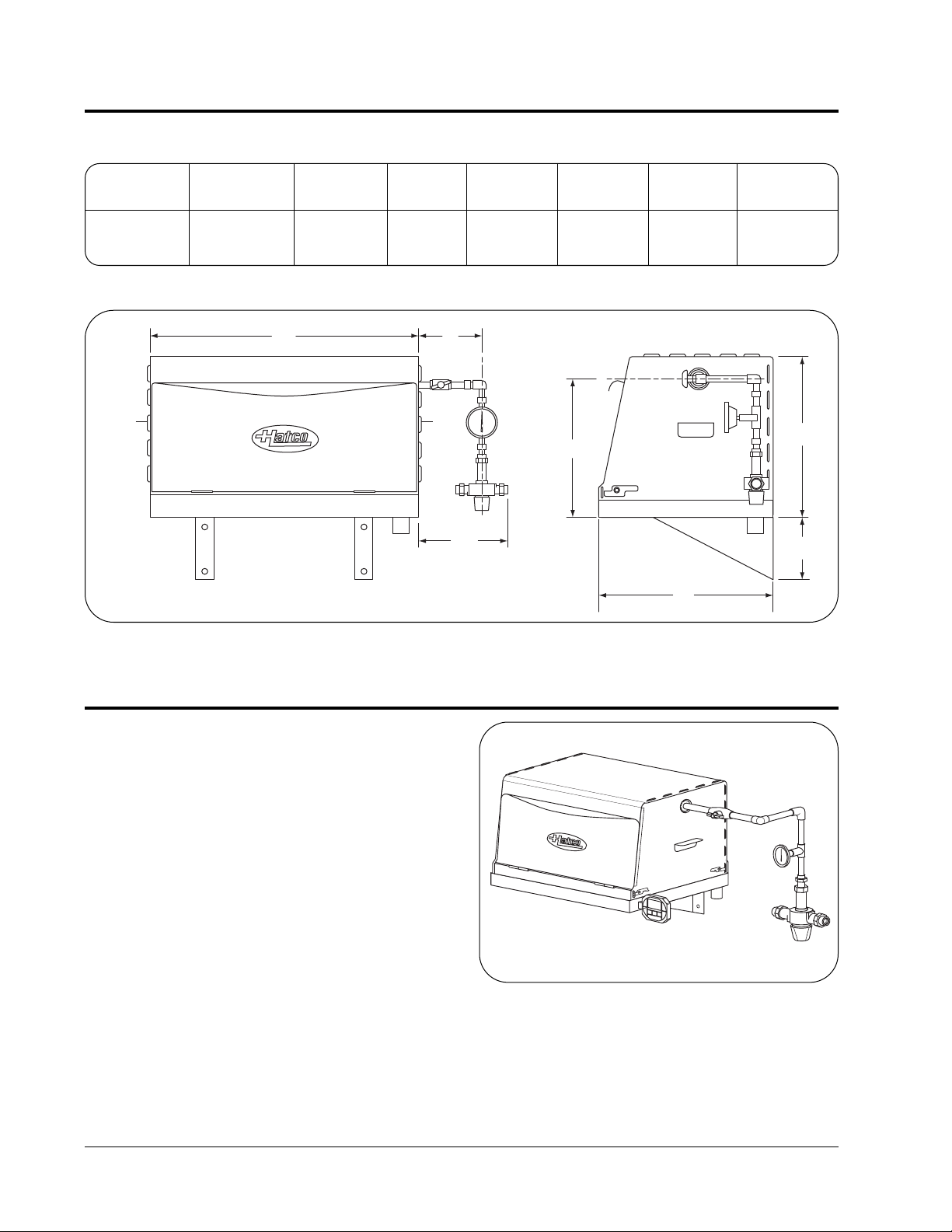
DIMENSIONS
A
B
C
D
E
F
G
Figure 1. HQT-1 Dimensions
HQT-1 MODEL
The Hatco Quick Thaw unit is specially designed to
rapidly and safely thaw frozen foods. Quick Thaw
units are easily assembled and disassembled for
cleaning/sanitizing purposes. The HQT-1 is
constructed of stainless steel providing strength,
durability, and the ease of cleaning. PVC tubing is
included for fast plumbing installation. Included with
1/2" NPT inlet fittings, is a mixing valve with built-in
check valves and screens, designed to control water
temperatures. The NSF listed dial face thermometer
displays the water temperature before it reaches the
removable spray arm. A large hinged door opening
allows for a 12" x 20" x 6" (305 x 508 x 152 mm)
perforated food pan (recommended) for rapidly
thawing frozen food in the HQT-1.
Accessories for the HQT-1 are a 12" x 20" x 6"
(305 x 508 x 152 mm) perforated food pan and a
wire support rack for thawing individual cryopacked
serving packages (up to two racks per pan).
T1
T2
H M S
S
T
A
R
T
/
S
T
O
P
CLOCK
RECALL
CLEAR
23:59
12:59
59
59
Figure 2. HQT-1 Quick Thaw Model,
shown with optional timer.
Width Width Width Depth Height Height Height
Model (A) (B) (C) (D) (E) (F) (G)
HQT-1 22-3/8" 5-1/2" 8-1/8" 16-3/4" 14-1/2" 12-1/4" 6"
(568 mm) (140 mm) (204 mm) (425 mm) (368 mm) (311 mm) (152 mm)
NOTE: Shipping weight, 48 lbs. (22 kg), includes packaging.
Page 5
Form No. HQTM-1006
3
INSTALLATION
WARNING
For safe and proper operation, the unit must
be located at a reasonable working height.
WARNING
To avoid injury or damage to the unit Hatco
mounting gussets must be used when mounting
unit to the wall. Mounting gussets have a
maximum weight capacity of 50 lbs.
(23 kg).
WARNING
To avoid injury or damage to the unit mount unit
to wall with proper hardware depending on wall
material. (Hardware not supplied.)
CAUTION
To avoid injury or damage to the unit DO NOT
move or relocate the unit while it contains any
food product.
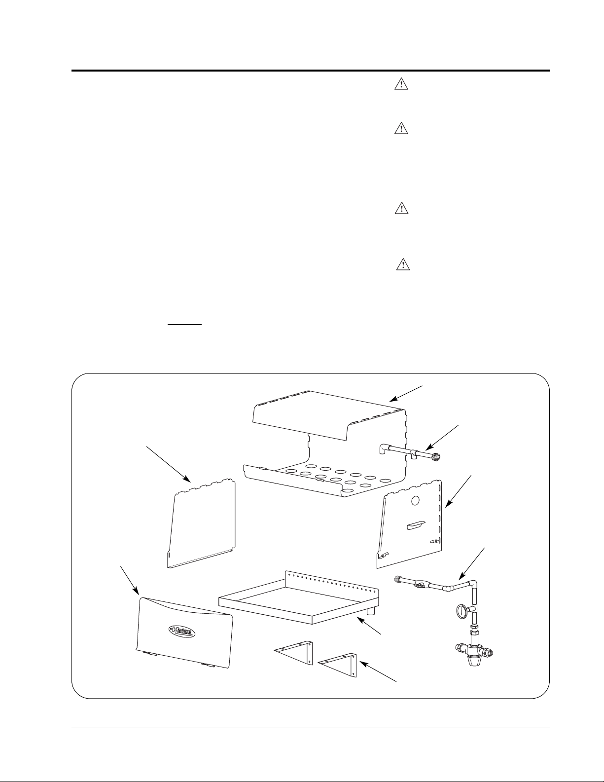
UNPACKING
Hatco Quick Thaw units are shipped from the factory
partially assembled. (See Figure 3.)
1. Remove HQT-1 unit parts from box.
NOTE: Contact Hatco if any of the components in
Figure 3 are missing or damaged.
2. Remove information packet. To prevent delay
in obtaining warranty coverage, fill out and
mail in the warranty card.
3. Remove tape and protective packaging from all
surfaces of unit.
LOCATION
NOTE: A qualified plumber is recommended for
providing hot and cold supply water lines with shut
off valves to the designated HQT-1 location.
Locate the unit to the lef
t side of the incoming water
line and close to a drain in compliance with State
and local plumbing codes.
Figure 3. HQT-1 Components
Left Side Panel
Right Side Panel
Spray Arm
Core Panel
Hinged Door
Shelf Gusset
Shelf/Drain Unit
Water Manifold
Page 6

Form No. HQTM-1006
4
INSTALLATION
CAVITY HOUSING ASSEMBLY
NOTE: Left side panel has no hole for the water
manifold connections. The side panels are not
interchangeable and will not fit into the shelf/drain
unit if assembled otherwise.
NOTE: To prevent scratches to countertop or floor,
use a piece of cardboard underneath unit while
doing assembly.
1. Position core panel upright onto the right side
edge.
2. A. Partially insert the tabs from the left side panel
into the slots on the top left hand side of the
core panel.
B. Align and insert tabs from the rear core panel
into the slots of the left side panel.
C.Insert the front tab from core panel into open
slot on the left side panel. Confirm all tabs are
fully inserted into the adjacent slots. Push lock
levers downward to fully secure the left side
panel to the core panel.
3. Turn core panel assembly end over end so the
left side panel is on the bottom.
4. Slide pins from the hinged door panel into open
hinges on core panel.
5. A. Partially insert the tabs from the right side
panel into the slots on the top right hand
side of the core panel.
B. Align and insert tabs from the rear core
panel into the slots of the right side panel.
C.Insert the front tab from core panel into
open slot on the right side panel. Confirm all
tabs are fully inserted into the adjacent
slots. Push lock levers downward to fully
secure the right side panel to the core panel.
B
A
C
Lock
Unlock
Figure 4. Right Side Panel Assembly
A
B
C
Unlock
Lock
Figure 5. Cavity Assembly
Left Side Panel
Core Panel
Lock Levers
Hinged Door
Right Side Panel
Lock Levers
Core Panel
Page 7

Form No. HQTM-1006
5
INSTALLATION
Figure 6. Shelf Assembly Mounting
SHELF INSTALLATION
CAUTION
Do not place anything on top of the unit; doing
so could damage the unit or subject personnel
to possible injury.
CAUTION
Use of excessive force when tightening
mounting screws may damage unit or wall.
NOTE: When mounting the shelf to the wall, secure
the gussets directly to the wall studs or use toggle
bolts (not supplied) if unable to secure unit directly
to wall studs.
1. Secure two shelf gussets to the underside of the
shelf/drain unit using the four stainless steel nuts
provided.
For proper drainage the shelf must be mounted level
or with left-hand side no more than 1/4" higher than
the right-hand side.
NOTE: Right-hand side should never be higher than
left-hand side.
2. Mount the shelf assembly to wall with
appropriate hardware at all four gusset mounting
holes. If gussets cannot be mounted directly into
wall studs, secure shelf to wall studs using at
least two of the shelf top mounting holes.
(See Figure 6.)
Drain pipe is to be routed in compliance with State
and local plumbing codes.
3. Attach drain pipe to the 1-1/2" (38 mm) diameter
drain tail pipe located on shelf/drain assembly.
4. Secure spray arm to cavity housing by twisting
the spray arm into the support bracket located
inside the cavity housing. The support bracket
will be located between the two spray heads.
(See Figure 7.)
5. With the spray heads on the spray arm pointing
downward connect the spray arm to the water
manifold, making sure O-Ring is seated into
groove on manifold end. (See Figure 8.) Hand
tighten only. Now core unit is set onto the shelf.
Plumber should then work backward from the
spray arm union to locate final plumbing path and
clamp (secure) the mixing valve to the wall.
Figure 7. Spray Arm Installation
Stainless Steel Nut
Support Bracket
Top Mounting
Holes
Gusset
Mounting Holes
6. Attach timer bracket anywhere on the shelf/drain
unit or any convenient location on the wall
nearby. (Optional)
NOTE: Do not mount timer bracket on the cavity
housing.
Page 8

Form No. HQTM-1006
6
INSTALLATION
Figure 8. Water Manifold Assembly
Mixing Valve
Temperature Gauge
Ball Valve
Spray Arm
WATER MANIFOLD ASSEMBLY
CAUTION
Do not overtighten unions or nuts. Overtightening may cause leaks.
CAUTION
Plumbing connections and drains are required
to be in accordance to all State and local
plumbing codes.
A qualified plumber is recommended for providing
1/2" hot and cold supply water lines with shut off
valves to the designated HQT-1 location.
NOTE: Installation instructions are provided with
mixing valve. Mixing valve is factory calibrated to the
low setpoint and will need to be adjusted after
installation. (Retain these instructions for future care
and maintenance of mixing valve.)
1. Connect the water manifold assembly directly to
mixing valve and secure to wall using a 3/4"
(19 mm) pipe support clamp or conduit clamp.
(Clamp is not provided.) (See Figure 8.)
NOTE: For proper alignment connect manifold
assembly with mixing valve to spray head prior to
affixing assembly to wall.
WARNING
For safe and proper operation the mixing valve
supplied must be installed directly to the water
manifold assembly. Improper installation may
cause unsafe health conditions.
2. Connect the hot and cold water supply lines to
the appropriate water inlets on the mixing valve.
See OPERATION section for adjusting water
temperature on mixing valve.
O-Ring
Page 9

Form No. HQTM-1006
7
OPERATION
TEMPERATURE CONTROL
Recommended thawing temperature is not to
exceed 69°F (21°C).
For ideal operating conditions, the cold water supply
should be at least 10°F (5.5°C) cooler than the
desired setpoint, and the hot water supply should be
at least 10°F (5.5°C) above the desired setpoint.
180°F (82°C) is the maximum temperature for the
hot water supply inlet on the mixing valve.
Setting the Temperature
1. Open ball valve to allow water to flow. W ait a few
minutes or until the temperature gauge gives a
consistent water temperature reading.
2. To adjust the water temperature, loosen the lock
screw beneath the red cap on the mixing valve
with the allen wrench provided. (See Figure 9.)
3. Pull down on the red cap and adjust to the
desired temperature. Allow water to run a few
minutes to confirm water temperature is
consistent.
4. Push red cap back into the locked position and
secure with lock screw.
NOTE: No further adjustment should be necessary.
Temperature Gauge
The temperature gauge monitors water temperature
within the water manifold assembly.
Figure 9. Adjusting Water Temperature
Red Cap
Lock Screw
Page 10

Form No. HQTM-1006
8
OPERATION
THAWING PROCEDURE
CAUTION
For safe and proper operation do not place food
product directly onto bottom of Hatco Quick
Thaw unit. Use of a perforated pan is
recommended for holding food product.
There are many variables that effect the amount of
time it takes to safely thaw frozen food product.
Times will vary based on the frozen food product
mass, water temperature and water pressure.
1. Open hinged door on cavity housing. Place
frozen food product into a perforated pan and set
inside cavity housing.
See ACCESSORIES section for optional food
holding pan and racks.
2. Close hinged door on cavity housing and open
up ball valve to release water flow.
NOTE: Water usage is approximately 2 gpm
(7.5 lpm) and may vary based on water pressure.
3. Set timer to the desired time. (Optional)
4. Close ball valve before opening hinged door to
remove thawed food product.
Page 11

Form No. HQTM-1006
9
OPERATION
T1
T2
HMS
S
T
A
R
T
/
S
T
O
P
CLOCK
RECALL
CLEAR
23:59
12:59
59
59
Figure 10. Timer Device
TIMER DEVICE (OPTIONAL)
Set Clock
1. Slide switch (located on the back of the unit) to
“CLOCK SET.”
2. Press “CLOCK” to select 12 or 24 hour display.
3. Press “H” to set hours. Press “M” to set minutes.
Press “S” to reset seconds to zero.
4. Slide switch back to “CLOCK/TIMER” for timer
operation.
Program Timer #1
1. Press “T1,” a “ONE” icon will appear above the
seconds digits.
2. Press “RECALL/CLEAR.” The timer digits will
flash.
3. Press “H” to set hours, “M” to set minutes, and
“S” to set seconds. To start over, press
“RECALL/CLEAR.”
4. Press “START/STOP” to start timer countdown.
Press again to pause or resume countdown.
5. At “00:00,” the alarm will beep. The timer will
begin to count up. Press “START/STOP” to stop
alarm. Press again to pause timer. Press
“RECALL/CLEAR” to recall the last set time.
Press again to reset to zero.
6. Press “CLOCK” to return to clock function. Timer
#’1’s digits will stop flashing.
Program Timer #2
1. Press “T2.” The clock digits will change to a timer
with a “TWO” icon.
2. Follow timer setting instructions as listed under
Timer #1.
3. To view the clock during Timer #2 countdown,
press “CLOCK.” The timer will continue to
operate. Press “T2” again to view Timer #2
countdown.
4. When both timers are in use, press “T1” or “T2”
to toggle between timer operations.
5. Each timer will count up to 23 hours, 59 minutes
and 59 seconds.
Count Up Feature
1. Both timers will also count up. Press “T1” or “T2”
to select a timer.
2. Press “RECALL/CLEAR” until the display shows
“00:00.”
3. Press “START/STOP” and the timer will count
up. Press “START/STOP” again to pause or
resume timing. Press “RECALL/CLEAR” to recall
the last set time. Press again to reset to zero.
NOTE: There is a static cling label over the digital
display and a strip under the battery cover to
prevent battery drain during shipping. Remove both
before use.
Page 12

Form No. HQTM-1006
10
MAINTENANCE
GENERAL
The Hatco Quick Thaw units are designed for
maximum durability and performance, with minimum
maintenance.
CLEANING
WARNING
To assure safe and proper operation additional
cleaning may be required depending upon
products being thawed and local codes applying
to sink thawing techniques.
WARNING
To avoid unsafe conditions do not mix products
that may contaminate each other during thawing
process.
CAUTION
Do not use harsh chemicals such as bleach or
cleaners containing bleach.
CAUTION
Cleaning and sanitizing is recommended at the
end of each days use.
CAUTION
Use only non-abrasive cleaners. Abrasive
cleaners could scratch the finish of your unit
marring its appearance and making it
susceptible to soil accumulation.
The cavity housing has been designed to allow for
easy disassembling, cleaning, and sanitizing. It is
recommended to clean and sanitize the HQT-1 at
the end of each days use.
1. Turn off water supply at the hot and cold shut off
valves.
2. Disconnect spray arm from water manifold and
remove from cavity housing for cleaning.
3. Lift the left side of the cavity housing out of
shelf/drain assembly. Move cavity housing to the
left until the water manifold union is cleared.
4. Remove cavity housing from shelf/drain
assembly and disassemble for cleaning and
sanitizing.
5. Clean and sanitize the drain shelf.
6. Refer to CAVITY ASSEMBLY section, and
Steps 4 & 5 in the SHELF INSTALLATION
section.
WARNING
If service is required on this unit, contact your
Authorized Hatco Service Agent, or contact the
Hatco Service Department at 800-558-0607 or
414-671-6350; fax 800-690-2966 or International
fax 414-671-3976.
WARNING
This product has no “user” serviceable parts. To
avoid damage to the unit or injury
to personnel, use only Authorized Hatco Service
Agents and Genuine Hatco Replacement Parts
when service is required.
WARNING
Genuine Hatco Replacement Parts are specified
to operate safely in the environments in which
they are used. Some aftermarket or generic
replacement parts do not have the
characteristics that will allow them to operate
safely in Hatco equipment. It is essential to use
Hatco Replacement Parts when repairing Hatco
equipment. Failure to use Hatco Replacement
Parts may subject operators of the equipment to
unsafe conditions and injury.
Page 13

Form No. HQTM-1006
11
ACCESSORIES
PERFORATED FOOD PAN
The perforated food pan allows for large frozen food
product to be safely handled within the HQT-1. The
perforated food pan measurements are
12" x 20" x 6" (305 x 508 x 152 mm)
WIRE SUPPORT RACK
The wire support rack allows the thawing of several
individually cryopacked serving packages at one
time. Two wire support racks fit into one perforated
food pan.
Figure 11. Perforated Food Pan
Figure 12. Wire Support Rack
TROUBLESHOOTING
SYMPTOM PROBABLE CAUSE CORRECTIVE ACTION
Hatco to supply information later.
Page 14

Form No. HQTM-1006
12
HATCO LIMITED WARRANTY
1. PRODUCT WARRANTY
Hatco warrants the products that it manufactures
(the “Products”) to be free from defects in
materials and workmanship, under normal
use and service, for a period of one (1) year from
the date of purchase when installed and
maintained in accordance with Hatco’s written
instructions or 18 months from the date of
shipment from Hatco. Buyer must establish the
product’s purchase date by returning Hatco’s
Warranty Registration Card or by other means
satisfactory to Hatco in its sole discretion.
Hatco warrants the following Product components
to be free from defects in materials and
workmanship from the date of purchase (subject
to the foregoing conditions) for the period(s) of
time and on the conditions listed below:
a) One (1) Year Parts and Labor PLUS One
(1) Additional Year Parts-Only Warranty:
Toaster Elements (metal sheathed)
Drawer Warmer Elements (metal sheathed)
Drawer Warmer Drawer Rollers and Slides
Food Warmer Elements (metal sheathed)
Display Warmer Elements (met al sheathed
air heating)
Holding Cabinet Elements (metal sheathed
air heating)
Built-In Heated Well Elements
(metal sheathed)
b) One (1) Year Parts and Labor PLUS Four
(4) Years Parts-Only Warranty on
pro-rated terms that Hatco will explain
at Buyer’s request:
3CS and FR Tanks
c) One (1) Year Parts and Labor PLUS Nine
(9) Years Parts-Only Warranty on:
Electric Booster Heater Tanks
Gas Booster Heater Tanks
THE FOREGOING WARRANTIES ARE
EXCLUSIVE AND IN LIEU OF ANY OTHER
WARRANTY, EXPRESSED OR IMPLIED,
INCLUDING BUT NOT LIMITED TO ANY
IMPLIED WARRANTY OF MERCHANTABILITY
OR FITNESS FOR A PARTICULAR PURPOSE
OR PATENT OR OTHER INTELLECTUAL
PROPERTY RIGHT INFRINGEMENT. Without
limiting the generality of the foregoing, SUCH
WARRANTIES DO NOT COVER: Coated
incandescent light bulbs, fluorescent lights, lamp
warmer heat bulbs, glass components, Product
failure in booster tank, fin tube heat exchanger, or
other water heating equipment, caused
by liming, sediment buildup, chemical attack or
freezing, Product misuse, tampering or
misapplication, improper installation, or application
of improper voltage.
2. LIMITATION OF REMEDIES AND
DAMAGES
Hatco’s liability and Buyer’s exclusive remedy
hereunder will be limited solely, at Hatco’s option,
to repair or replacement by a Hatco-authorized
service agency (other than where Buyer is
located outside of the United States, Canada,
United Kingdom or Australia in which case
Hatco’s liability and Buyer’s exclusive remedy
hereunder will be limited solely to replacement of
part under warranty) with respect to any claim
made within the applicable warranty period
referred to above. Hatco reserves the right to
accept or reject any such claim in whole or in part.
Hatco will not accept the return of any Product
without prior written approval from Hatco, and all
such approved returns shall be made at Buyer’s
sole expense. HATCO WILL NOT BE LIABLE,
UNDER ANY CIRCUMSTANCES, FOR
CONSEQUENTIAL OR INCIDENTAL
DAMAGES, INCLUDING BUT NOT LIMITED TO
LABOR COSTS OR LOST PROFITS
RESUL TING FROM THE USE OF OR INABILITY
TO USE THE PRODUCTS OR FROM THE
PRODUCTS BEING INCORPORATED IN OR
BECOMING A COMPONENT OF ANY OTHER
PRODUCT OR GOODS.
Page 15

Form No. HQTM-1006
13
NOTES
Page 16

HATCO CORPORATION
P.O. Box 340500, Milwaukee, WI 53234-0500 U.S.A.
(800) 558-0607 (414) 671-6350
Parts & Service Fax (800) 690-2966 Int’l. Fax (414) 671-3976
www.hatcocorp.com
HATCO AUTHORIZED PARTS DISTRIBUTORS
Printed in U.S.A. October 2006
ALABAMA
Jones McLeod Appl. Svc.
Birmingham 205-251-0159
ARIZONA
Auth. Comm. Food Equip.
Phoenix 602-234-2443
Byassee Equipment Co.
Phoenix 602-252-0402
CALIFORNIA
Industrial Electric
Commercial Parts & Service, Inc.
Huntington Beach 714-379-7100
Chapman Appl. Service
San Diego 619-298-7106
P & D Appliance
Commercial Parts & Service, Inc.
S. San Francisco 650-635-1900
COLORADO
Hawkins Commercial Appliance
Englewood 303-781-5548
FLORIDA
Whaley Foodservice Repair
Jacksonville 904-725-7800
Universal Restaurant Services
Miami 305-593-5488
Nass Service Co., Inc.
Orlando 407-425-2681
B.G.S.I.
Pompano Beach 954-971-0456
Comm. Appliance Service
Tampa 813-663-0313
GEORGIA
TWC Services
Smyrna 770-438-9797
Heritage Service Group
Norcross 866-388-9837
Southeastern Rest. Svc.
Norcross 770-446-6177
HA
WAII
Burney’s Comm. Service, Inc.
Honolulu 808-848-1466
Food Equip Parts & Service
Honolulu 808-847-4871
ILLINOIS
Parts Town
Lombard 708-865-7278
Eichenauer Elec. Service
Decatur 217-429-4229
Midwest Elec. Appl. Service
Elmhurst 630-279-8000
Cone’s Repair Service
Moline 309-797-5323
INDIANA
GCS Service
Indianapolis 317-545-9655
IOW
A
Electric Motor Service Co.
Davenport 319-323-1823
Goodwin Tucker Group
Des Moines 515-262-9308
KENTUCKY
GCS Service
Louisville 502-367-1788
LOUISIANA
Chandlers Parts & Service
Baton Rouge 225-272-6620
MAR
YLAND
Electric Motor Service
Baltimore 410-467-8080
GCS Service
Silver Spring 301-585-7550
MASSACHUSETTS
Ace Service Co., Inc.
Needham 781-449-4220
MICHIGAN
Commercial Kitchen Service
Bay City 517-893-4561
Bildons Appliance Service
Detroit 248-478-3320
Midwest Food Equip. Service
Grandville 616-261-2000
MINNESOT
A
GCS Service
Minneapolis 612-546-4221
MISSOURI
General Parts
Kansas City 816-421-5400
Commercial Kitchen Services
St. Louis 314-890-0700
Kaemmerlen Parts & Service
St. Louis 314-535-2222
NEBRASKA
Anderson Electric
Omaha 402-341-1414
NEV
ADA
Burney’s Commercial
Las Vegas 702-736-0006
Hi. Tech Commercial Service
N. Las Vegas 702-649-4616
NEW JERSEY
Jay Hill Repair
Fairfield 973-575-9145
Service Plus
Flanders 973-691-6300
NEW
YORK
Acme American Repairs, Inc.
Brooklyn 718-456-6544
Alpro Service Co.
Brooklyn 718-386-2515
Appliance Installation
Buffalo 716-884-7425
Northern Parts Dist.
Plattsburgh 518-563-3200
J.B. Brady, Inc.
Syracuse 315-422-9271
NORTH CAROLINA
Authorized Appliance
Charlotte 704-377-4501
OHIO
Akron/Canton Comm. Svc. Inc.
Akron 330-753-6635
Certified Service Center
Cincinnati 513-772-6600
Commercial Parts and Service
Columbus 614-221-0057
Electrical Appl. Repair Service
Independence 216-459-8700
E. A. Wichman Co.
Toledo 419-385-9121
OKLAHOMA
Hagar Rest. Service, Inc.
Oklahoma City 405-235-2184
Krueger, Inc.
Oklahoma City 405-528-8883
OREGON
Ron’s Service, Inc.
Portland 503-624-0890
PENNSYL
VANIA
Elmer Schultz Services
Philadelphia 215-627-5401
FAST Comm. Appl. Service
Philadelphia 215-288-4800
Appliance Installation & Service
Pittsburgh 412-809-0244
K & D Service Co.
Harrisburg 717-236-9039
Electric Repair Co.
Reading 610-376-5444
RHODE ISLAND
Marshall Electric Co.
Providence 401-331-1163
SOUTH CAROLINA
Whaley Foodservice Repair
W. Columbia 803-791-4420
TENNESSEE
Camp Electric
Memphis 901-527-7543
TEXAS
GCS Service
Fort Worth 817-831-0381
Armstrong Repair Service
Houston 713-666-7100
Commercial Kitchen Repair Co.
San Antonio 210-735-2811
UT
AH
La Monica’s Rest. Equip. Service
Murray 801-263-3221
VIRGINIA
Daubers
Norfolk 757-855-4097
Daubers
Springfield 703-866-3600
W
ASHINGTON
Restaurant Appl. Service
Seattle 206-524-8200
WISCONSIN
A.S.C., Inc.
Madison 608-246-3160
A.S.C., Inc.
Milwaukee 414-543-6460
CANADA
ALBERTA
Key Food Equipment Service
Edmonton 780-438-1690
BRITISH COLUMBIA
Key Food Equipment Service
Vancouver 604-433-4484
MANIT
OBA
Air Rite, Inc.
Winnepeg 204-895-2300
N
EW BRUNSWICK
EMR Services, Ltd.
Moncton 506-855-4228
ONT
ARIO
R.G. Henderson Ltd.
Toronto 416-422-5580
Choquette CKS
Ottawa 613-739-8458
QUÉBEC
Choquette CKS
Montreal 514-722-2000
Choquette CKS
Québec City 418-681-3944
Parts No. 07.04.394.00 Form No. HQTM-1006
 Loading...