

Page 1
DRAWER WARMER
HDW & HDW-B Series
Installation &
Operating Manual
I&W #07.05.014.00
Page 2

i
INTRODUCTION
Hatco Drawer Warmers are designed to keep all foods at
optimum serving temperatures without affecting quality.
HDW models include an attached cord and plug set
while the HDW-B models have a flexible conduit for
built-in installation.
All Hatco Drawer Warmers are built for tough kitchen
duty with rugged stainless steel construction, heavy-duty
hardware, stainless steel slides and positive-closing
drawers. They keep everything from meat to vegetables
to rolls hot and flavor-fresh until served.
Each drawer features individual controls so you can
hold a wider variety of hot foods during peak serving
periods.
This manual provides the installation, safety and operating instructions for the Heated Drawer Warmer. We recommend all installation, operating and safety instructions appearing in this manual be read prior to installation or operation of your Hatco Drawer Warmer. Safety
instructions that appear in this manual after a warning
symbol and the words WARNING or CAUTION
printed in bold face are important. Warning means there
is the possibility of personal injury to yourself or others.
Caution means there is the possibility of damage to the
unit.
Your Hatco Drawer Warmer is a product of extensive
research and field testing. The materials used were
selected for maximum durability, attractive appearance
and optimum performance. Every unit is thoroughly
inspected and tested prior to shipment.
CONTENTS
Important Owner Information..................................i
Introduction.................................................................i
Important Safety Instructions ..................................1
Model Descriptions ....................................................1
All Models............................................................1
HDW ....................................................................1
HDW-N ................................................................1
HDW-B ................................................................1
HDW-BN..............................................................1
Specifications..............................................................2
Electrical Rating Chart - HDW............................2
Electrical Rating Chart - HDW-N........................2
Electrical Rating Chart - HDW-B........................3
Electrical Rating Chart - HDW-BN.....................3
Dimensions - HDW & HDW-N ...........................4
Dimensions - HDW-B & HDW-BN ....................4
Plug Configurations .............................................5
Installation..................................................................5
HDW & HDW-N .................................................5
HDW-B & HDW-BN ...........................................5
Location................................................................6
Operation....................................................................7
All Models............................................................7
Food Holding Capacity ........................................7
Food Holding Guide ............................................7
Maintenance ...............................................................8
Accessories..................................................................8
Hatco Limited Warranty...........................................9
Authorized Parts Distributors.................Back Cover
Record the model number, serial number (located on the
back of HDW models, inside left panel on HDW-B
models), voltage and purchase date of your Drawer
Warmer in the spaces below. Please have this information available when calling Hatco for service assistance.
Model No.____________________________________
Serial No. ____________________________________
Voltage ______________________________________
Date of Purchase _______________________________
IMPORTANT OWNER INFORMATION
Business Hours: 8:00 a.m. to 5:00 p.m.
Central Standard Time
(Summer Hours: June to September -
8:00 a.m. to 5:00 p.m. C.D.T.
Monday through Thursday
8:00 a.m. to 3:30 p.m. C.D.T. Friday)
Telephone: (800) 558-0607; (414) 671-6350
Parts & Service Fax: (800) 690-2966
(414) 671-3976 (International)
!
Printed March 1999
Form No. HDWM-0399
Page 3
1
IMPORTANT SAFETY INSTRUCTIONS
Read the following important safety instructions to
avoid personal injury and/or damage to the equipment.
1. To avoid any injury, turn the power switch off and
allow to cool before performing any maintenance.
On freestanding units, unplug the electrical cord
from the power source as well.
2. Some exterior and interior surfaces on the unit will
get hot. Use caution when touching these areas to
avoid injury.
3. To avoid any injury, use caution when opening
drawer. Heated/moisturized air escapes when
drawer is open.
4. On free-standing units, plug unit into an electrical
outlet of the correct voltage, size and plug configu-
ration. If the plug and receptacle do not match,
contact a qualified electrician to determine the
proper voltage and size and install the proper electrical outlet. On built-in units, final connections
should be made by a qualified electrician.
5. For safe and proper operation, the unit must be
located a reasonable distance from combustible
walls and materials. If safe distances are not maintained, discoloration or combustion could occur.
6. Locate the unit in an area that is convenient for
use. The location should be level to prevent the
unit or its contents from accidentally falling, and
strong enough to support the weight of the unit
and food.
7. Abrasive cleaners could scratch the finish of your
unit.
ALL MODELS
The Hatco Drawer Warmers are built of rugged stainless
steel with durable nylon rollers, 12 gauge stainless steel
slides and heavy-duty hardware. Each drawer features
adjustable sliding vents for humidity control in addition
to a recessed on-off switch, thermostat and temperature
monitor. Standard size pans 6" (15 cm) deep are supplied with each drawer. The insulated top and sides provide maximum energy efficiency and the heating elements are warranted for two years.
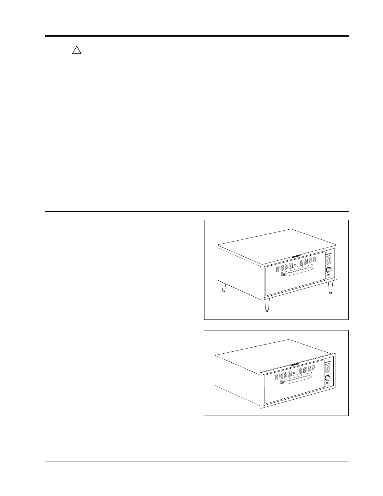
HDW MODELS
One, two and three drawer freestanding units are
equipped with 4" (10cm) legs as standard equipment.
Four drawer freestanding units are equipped with 6"
(15 cm) stainless steel legs.
HDW-N MODELS
These heated Drawer Warmers have all the features of
the HDW freestanding models but have a narrower profile for smaller space requirements. These units are
available in 1, 2 and 3 drawer models.
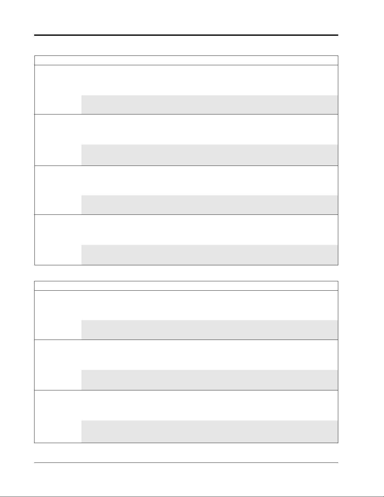
HDW-B MODELS
These heated Drawer Warmers come equipped with a
flexible conduit for built-in applications. These units are
available in 1, 2 and 3 drawer models.
HDW-BN MODELS
These heated Drawer Warmers include all the features
WARNINGS/CAUTIONS
!
MODEL DESCRIPTION
Figure 1. Model HDW-1
Figure 2. Model HDW-1B
Printed March 1999
Form No. HDWM-0399
of the HDW-B models but have a narrower profile for
smaller space requirements. These units are available in
1, 2 and 3 drawer models.
R
E
M
R
A
W
R
E
W
A
R
D
N - HO
UTIO
A
C
ER PAN.
PLACE NO MORE THAN 1/4" OF
IN DRAW
CAUTION:
D'EAU DANS LA CUVETTE DU TIROIR
ATTENTION:NE PAS METTRE PLUS DE 1/4 PO
T
ACO
N
O
F
F
O
R
E
W
O
P
T
- HO
N
TIO
AU
C
PLACE NO MORE THAN 1/4" OF
IN DRAWER PAN.
CAUTION:
D'EAU DANS LA CUVETTE DU TIROIR
ATTENTION:NE PAS METTRE PLUS DE 1/4 PO
R
E
M
R
A
W
R
E
W
A
R
D
ACO
N
O
F
F
O
R
E
W
O
P
Page 4
Printed March 1999
Form No. HDWM-0399
2
SPECIFICATIONS
ELECTRICAL RATING CHART - HDW MODELS
The electrical information in the shaded areas pertains to Export models only.
ELECTRICAL RATING CHART - HDW-N MODELS
Model Voltage Watts Amps Plug Configuration Shipping Weight
120 450 3.8 NEMA 5-15P 97 lbs. ( 44 kg)
208 450 2.2 NEMA 6-15P 97 lbs. ( 44 kg)
HDW-1 240 450 1.9 NEMA 6-15P 97 lbs. ( 44 kg)
220 450 2.1 CEE 7/7 Schuko 97 lbs. ( 44 kg)
240 450 1.9 BS-1363 97 lbs. ( 44 kg)
120 900 7.5 NEMA 5-15P 168 lbs. ( 76 kg)
208 900 4.3 NEMA 6-15P 168 lbs. ( 76 kg)
HDW-2 240 900 3.8 NEMA 6-15P 168 lbs. ( 76 kg)
220 900 4.1 CEE 7/7 Schuko 168 lbs. ( 76 kg)
240 900 3.8 BS-1363 168 lbs. ( 76 kg)
120 1350 11.3 NEMA 5-15P 232 lbs. (106 kg)
208 1350 6.5 NEMA 6-15P 232 lbs. (106 kg)
HDW-3 240 1350 5.6 NEMA 6-15P 232 lbs. (106 kg)
220 1350 6.1 CEE 7/7 Schuko 232 lbs. (106 kg)
240 1350 5.6 BS-1363 232 lbs. (106 kg)
120 1800 15.0 NEMA 5-20P 296 lbs. (135 kg)
208 1800 8.7 NEMA 6-15P 296 lbs. (135 kg)
HDW-4 240 1800 7.5 NEMA 6-15P 296 lbs. (135 kg)
220 1800 8.2 CEE 7/7 Schuko 296 lbs. (135 kg)
240 1800 7.5 BS-1363 296 lbs. (135 kg)
Model Voltage Watts Amps Plug Configuration Shipping Weight
120 450 3.8 NEMA 5-15P 97 lbs. ( 44 kg)
208 450 2.2 NEMA 6-15P 97 lbs. ( 44 kg)
HDW-1N 240 450 1.9 NEMA 6-15P 97 lbs. ( 44 kg)
220 450 2.1 CEE 7/7 Schuko 97 lbs. ( 44 kg)
240 450 1.9 BS-1363 97 lbs. ( 44 kg)
120 900 7.5 NEMA 5-15P 168 lbs. ( 76 kg)
208 900 4.3 NEMA 6-15P 168 lbs. ( 76 kg)
HDW-2N 240 900 3.8 NEMA 6-15P 168 lbs. ( 76 kg)
220 900 4.1 CEE 7/7 Schuko 168 lbs. ( 76 kg)
240 900 3.8 BS-1363 168 lbs. ( 76 kg)
120 1350 11.3 NEMA 5-15P 232 lbs. (105 kg)
208 1350 6.5 NEMA 6-15P 232 lbs. (105 kg)
HDW-3N 240 1350 5.6 NEMA 6-15P 232 lbs. (105 kg)
220 1350 6.1 CEE 7/7 Schuko 232 lbs. (105 kg)
240 1350 5.6 BS-1363 232 lbs. (105 kg)
Page 5

ELECTRICAL RATING CHART - HDW-BN MODELS
Printed March 1999
Form No. HDWM-0399
3
SPECIFICATIONS
The electrical information in the shaded areas pertains to Export models only.
ELECTRICAL RATING CHART - HDW-B MODELS
Model Voltage Watts Amps Wiring Shipping Weight
120 450 3.8 Conduit 88 lbs. ( 40 kg)
208 450 2.2 Conduit 88 lbs. ( 40 kg)
HDW-1BN 240 450 1.9 Conduit 88 lbs. ( 40 kg)
220 450 2.1 Conduit 88 lbs. ( 40 kg)
240 450 1.9 Conduit 88 lbs. ( 40 kg)
120 900 7.5 Conduit 159 lbs. ( 72 kg)
208 900 4.3 Conduit 159 lbs. ( 72 kg)
HDW-2BN 240 900 3.8 Conduit 159 lbs. ( 72 kg)
220 900 4.1 Conduit 159 lbs. ( 72 kg)
240 900 3.8 Conduit 159 lbs. ( 72 kg)
120 1350 11.3 Conduit 223 lbs. (101 kg)
208 1350 6.5 Conduit 223 lbs. (101 kg)
HDW-3BN 240 1350 5.6 Conduit 223 lbs. (101 kg)
220 1350 6.1 Conduit 223 lbs. (101 kg)
240 1350 5.6 Conduit 223 lbs. (101 kg)
Model Voltage Watts Amps Wiring Shipping Weight
120 450 3.8 Conduit 88 lbs. ( 40 kg)
208 450 2.2 Conduit 88 lbs. ( 40 kg)
HDW-1B 240 450 1.9 Conduit 88 lbs. ( 40 kg)
220 450 2.1 Conduit 88 lbs. ( 40 kg)
240 450 1.9 Conduit 88 lbs. ( 40 kg)
120 900 7.5 Conduit 159 lbs. ( 72 kg)
208 900 4.3 Conduit 159 lbs. ( 72 kg)
HDW-2B 240 900 3.8 Conduit 159 lbs. ( 72 kg)
220 900 4.1 Conduit 159 lbs. ( 72 kg)
240 900 3.8 Conduit 159 lbs. ( 72 kg)
120 1350 11.3 Conduit 223 lbs. (101 kg)
208 1350 6.5 Conduit 223 lbs. (101 kg)
HDW-3B 240 1350 5.6 Conduit 223 lbs. (101 kg)
220 1350 6.1 Conduit 223 lbs. (101 kg)
240 1350 5.6 Conduit 223 lbs. (101 kg)
Page 6

4
SPECIFICATIONS
Printed March 1999
Form No. HDWM-0399
Model (A) Depth (B) Width (C) Height
HDW-1 22-5/8" 29-1/4" 11"
(58 cm) (74 cm) (28 cm)
HDW-2 22-5/8" 29-1/4" 21-1/8"
(58 cm) (74 cm) (54 cm)
HDW-3 22-5/8" 29-1/4" 31-1/4"
(58 cm) (74 cm) (79 cm)
HDW-4 22-5/8" 29-1/4" 41-3/8"
(58 cm) (74 cm) (105 cm)
HDW-1N 27" 20-3/16" 11"
(69 cm) (53 cm) (28 cm)
HDW-2N 27" 20-3/16" 21-1/8"
(69 cm) (53 cm) (54 cm)
HDW-3N 27" 20-3/16" 31-1/4"
(69 cm) (53 cm) (79 cm)
DIMENSIONS - HDW & HDW-N
Figure 3. Dimensions - HDW & HDW-N Models
Model (A) Depth (B) Width (C) Height
HDW-1B 22-5/16" 28-5/16" 9-3/4"
(57 cm) (72 cm) (25 cm)
HDW-2B 22-5/16" 28-5/16" 19-15/16"
(57 cm) (72 cm) (51 cm)
HDW-3B 22-5/16" 28-5/16" 30-1/16"
(57 cm) (72 cm) (76 cm)
HDW-1BN 26-3/4" 20-9/16" 9-3/4"
(68 cm) (52 cm) (25 cm)
HDW-2BN 26-3/4" 20-9/16" 19-15/16"
(68 cm) (52 cm) (51 cm)
HDW-3BN 26-3/4" 20-9/16" 30-1/16"
(68 cm) (52 cm) (76 cm)
DIMENSIONS - HDW-B & HDW-BN
Figure 4. Dimensions - HDW-B & HDW-BN Models
A
A
B
B
C
C
C
C
C
C
C
Page 7

Printed March 1999 Form No. HDWM-0399
5
SPECIFICATIONS
INSTALLATION
On free-standing units, plug unit into an electrical
outlet of the correct voltage, size and plug configuration. If the plug and receptacle do not match, contact
a qualified electrician to determine the proper voltage and size and install the proper electrical outlet.
On built-in units, final connections should be made
by a qualified electrician.
PLUG CONFIGURATIONS
Free-standing units are supplied from the factory with
an electrical cord and plug installed. Plugs are supplied
according to the applications as shown in Figure 5.
Built-in units are supplied with a flexible conduit and
applicable wiring.
CAUTION
!
Figure 5. Plug Configuration
NEMA 5-15P
NEMA 5-20P
NEMA 6-15P
CEE 7/7 Schuko
BS-1363
HDW & HDW-N MODELS
Care should be taken when unpacking shipping carton to
avoid damage to unit and components enclosed.
1. Remove the unit from the carton.
2. Remove plastic bag containing four adjustable legs
from inside the drawer.
CAUTION
Legs must be installed prior to operation of the unit.
3. Carefully lay unit on its side (requires 2 people).
Install legs to bottom of unit as shown in Figure 6.
Hand tighten legs until snug. Do not overtighten.
CAUTION
Do not lay unit on the front or back side or damage
to unit could occur.
4. Return unit to the upright position.
5. Remove all tape from the unit.
NOTE: Legs are adjustable for leveling the unit. Use a
9/16" (14 mm) open-end wrench to make leveling
adjustments once the unit is placed in final position.
HDW-B & HDW-BN MODELS
Care should be taken when unpacking shipping carton to
avoid damage to unit and components enclosed.
1. Remove the unit from the carton.
!
!
Figure 6. Adjustable Legs
Leg Adjustment
Adjust leg using a 9/16"
(14 mm) open-end
wrench and turning bottom of leg accordingly.
Leg Installation
!
CAUTION
Do not lay unit on the front or back side or damage
to the unit could occur.
2. Read information under Location before determining
installation site.
3. Determine the cabinet size opening using the chart in
Figure 7.
NOTE: Maintain a minimum clearance of 1" (2.5 cm)
between the cutout opening and the floor.
4. After cabinet opening is prepared to the proper size,
Page 8

a lock strip (not supplied by Hatco) must be permanently fastened to the lower front inside lip of the
cabinet opening. See Figure 7.
5. Partially insert the Drawer Warmer into the opening,
making sure the flexible conduit is fed into the wire
connection area first. Have a qualified electrician
connect the wires at this time.
WARNING
Final electrical connections must be made by a qualified electrician.
6. Before completely installing the unit into the opening, apply a bead of NSF approved sealant between
the Drawer Warmer flange and the cabinet facing.
7. Slide the unit completely into the opening until front
locking studs drop behind locking strip and lock into
place. To verify installation, pull bottom drawer fully
out and gently pull to ensure unit is securely locked
in place.
Printed March 1999
Form No. HDWM-0399
CAUTION
For safe and proper operation, the unit must be
located a reasonable distance from combustible walls
and materials. If safe distances are not maintained,
discoloration or combustion could occur.
!
WARNING
Locate the unit in an area that is convenient for use.
The location should be level to prevent the unit or its
contents from accidentally falling, and strong enough
to support the weight of the unit and its contents.
!
!
LOCATION
INSTALLATION
6
Figure 7. Built-In Cutout Dimensions
Model (D) Depth (W) Width (H) Height
Dimension Dimension Dimension
HDW-1B 23-3/4" 28-5/16" 10-1/8"
(60 cm) (72 cm) (26 cm)
HDW-2B 23-3/4" 28-5/16" 20-1/4"
(60 cm) (72 cm) (51 cm)
HDW-3B 23-3/4" 28-5/16" 30-3/8"
(60 cm) (72 cm) (77 cm)
HDW-1BN 28-1/8" 19-5/8" 10-1/8"
(71 cm) (50 cm) (26 cm)
HDW-2BN 28-1/8" 19-5/8" 20-1/4"
(71 cm) (50 cm) (51 cm)
HDW-3BN 28-1/8" 19-5/8" 30-3/8"
(71 cm) (50 cm) (77 cm)
W
A
A
.125"
(.5 cm)
.875"
(2 cm)
Drawer Bezel Outline
Lock Strip
Section A-A
D
H
H
.5"
(1 cm)
.5
"
(1 cm)
.438
"
(1 cm)
.422"
(1 cm)
Page 9

Printed March 1999
Form No. HDWM-0399
OPERATION
7
ALL MODELS
1. On freestanding models, plug unit into an electrical
outlet of the correct voltage, size and plug configuration. See Specifications for details.
2. Turn the Power Switch to the ON position. See
Figure 8.
3. Turn the Thermostat Control to the desired temperature settings. See the Recommended Settings chart on
the control panel or the Food Holding Guide in this
manual.
4. Allow unit 15-20 minutes to reach operating temperature.
5. Adjust the drawer vents for desired humidity control
by sliding the locking knob on the drawer front. See
Figure 9. Opening the vents all the way allows maximum moisture to escape.
NOTE: Proper vent adjustment depends on the type and
amount of food held, as well as the frequency of drawer
opening.
NOTE: For additional moisture, water can be added
(approximately 1/4" (.6 cm) of water) to the optional
water/spillage pan before inserting the food pan into the
drawer. Check water level periodically. Add water as
necessary. Use of splash baffle is recommended to prevent water from splashing into the cabinet interior when
opening and closing a drawer.
Figure 8. Operating Controls
Figure 9. Drawer Vents
WARNING
Some exterior and interior surfaces on the unit will
get hot. Use caution when touching these areas to
avoid injury.
!
Power Switch
Thermostat Control
Temperature Gauge
Recommended
Settings Chart
NOTE: Use of softened or distilled water is recommended to preserve the life of electrical and mechanical
components. If hard water is used, the pan will require
periodic cleaning and deliming. See Maintenance section for deliming instructions.
RECOMMENDED TYPE OF VENT
PRODUCT STORAGE TEMPERATURE HEAT CONTROL
Rolls, Hard 160° - 185° F (71° - 85° C) Dry Closed
Rolls, Soft 150° - 175° F (66° - 79° C) Moist Open-Half
Vegetables 175° - 185° F (66° - 85° C) Moist Open-Half
Meat, Poultry 165° - 185° F (74° - 85° C) Dry Closed
Fish 165° - 185° F (74° - 85° C) Moist Open
Casseroles 150° - 175° F (66° - 79° C) Dry Closed
Pies, Desserts 160° - 185° F (71° - 85° C) Dry Closed
Tacos, Tortillas 150° - 160° F (66° - 71° C) Moist Open-Half
FOOD HOLDING GUIDE
FOOD HOLDING CAPACITY
A standard drawer has the following capacity:
Dinner Rolls: 6-8 dozen
Ribs: 25-30 lbs. (11-14 kg)
Potatoes: 3-3-1/2 dozen
WARNING
To avoid injury, use caution when opening drawer.
Heated/moisturized air escapes when drawer is
opened.
!
HATCO DRAWER WARMER
50 70 90
10 20 30
RECOMMENDED SETTINGS
Recommended
Type
Storage
of
Temp.
Product
Heat
Rolls, Hard
160-185
F
Dry
F
Rolls, Soft
150-175
Moist
F
Vegetables
175-185
Moist
F
Meat, Poultry
165-185
Dry
F
Fish
165-185
Moist
F
Casseroles
150-175
Dry
F
Pies, Desserts
160-185
Dry
F
Tacos, Tortillas
150-160
Moist
4
3
2
OFF
5
1
6
T
E
E
M
R
P
U
E
T
R
A
POWER
F
C
Vent
Control
Setting
Closed
Open-Half
Open-Half
Closed
Open
Closed
Closed
Open-Half
ON
F
1/4" O
N
A
E TH
O
R
O
M
IR
O
E 1/4 P
O
.
N
D
E
S
AN
TIR
LU
U
P
LAC
P
D
P
ER
E
:
W
N
TTE
TR
A
E
ET
TIO
DR
UV
M
AU
IN
S
C
A C
A
L
P
S
E
N
:
AN
N
D
AU
NTIO
'E
D
TE
AT
Page 10

ACCESSORIES
WATER/SPILLAGE PAN
The water/spillage pan fits in the drawer underneath the
food pan and can be used to humidify the heating area
or keep spillage from the cabinet interior. Splash baffle
is recommended.
SPLASH BAFFLE
The splash baffle is used with the optional water/
spillage pan. Fabricated of stainless steel, the baffle fits
into the bottom of the water/spillage pan, over the water
bath, to prevent water from splashing into the cabinet
interior when opening and closing a drawer, while
allowing humidity to escape.
FOOD PANS
Food pans 12"W x 20"L (31 x 51 cm) are available in
depth sizes of 2", 4" & 6" (5, 10 & 15 cm).
CHIP GUARD
The chip guard completely shields the heating element,
preventing any food product, such as tortilla chips, from
coming in contact with the heating element.
ADJUSTABLE LEGS - 6" (15 CM)
6" (15 cm) stainless steel adjustable legs are available
for one, two and three drawer freestanding units.
LOCKING CASTERS - 2" (6 cm) Diameter
These locking casters are available for the freestanding
HDW-1, HDW-2 and HDW-3 models. The casters add
4-1/4" (10 cm) to the height of the Drawer Warmer.
LOCKING CASTERS - 3" (8 cm) Diameter
These locking casters are available for the freestanding
HDW-1, HDW-2 and HDW-3 models. The casters add
5-1/4" (13 cm) to the height of the Drawer Warmer.
LOCKING CASTERS - 4" (10 cm) Diameter
These locking casters are available for the freestanding
HDW-1, HDW-2, HDW-3 and HDW-4 models. The
casters add 6-1/4" (16 cm) to the height of the Drawer
Warmer.
CLEANING
Hatco Drawer Warmers are designed for maximum
durability and performance, with minimum maintenance.
WARNING
To avoid any injury, turn the power switch off and
allow unit to cool before performing maintenance.
On freestanding units, unplug the electrical cord
from the power source as well.
To preserve the finish of the Drawer Warmer, it is recommended that the surfaces be wiped daily with a damp
cloth. Food pans should be removed and washed.
Stubborn stains may be removed with a good non-abrasive cleaner. Hard to reach areas should be cleaned with
a small brush and mild soap.
CAUTION
Abrasive cleaners could scratch the finish of your
Drawer Warmer.
REMOVING LIME & MINERAL DEPOSITS
(Models with optional water pan)
NOTE: If the water has an excessive amount of lime or
mineral content, use the following instructions for periodic cleaning and de-liming of the water pan.
1. Turn the power switch off. On freestanding units,
unplug the cord from the power source.
!
2. After the unit has cooled down, remove the water
pan.
3. Fill the water pan with a mixture of water and
delimer.
NOTE: The delimer used should be a safe, non-toxic,
non-corrosive solution. Follow the delimer’s instructions
for proper mixture of water and de-limer solution.
4. Allow the pan to stand with the mixture for the recommended period of time. (The time required will
vary depending on the solution used and amount of
deposits in the pan.)
5. After the deliming period, drain the solution from
the pan.
6. Continue to fill and rinse the pan with water only,
until the pan is clean.
7. Install the pan into the unit. On freestanding units,
plug the power cord into the receptacle and fill the
pan as usual for daily operation (1/4" (.6 cm) of
water is recommended).
NOTE: The lime and mineral content of the water used
for daily operation will determine how often de-liming
procedure must be performed.
!
MAINTENANCE
Printed March 1999
Form No. HDWM-0399
8
Page 11

Printed March 1999
Form No. HDWM-0399
9
LIMITED WARRANTY
1. PRODUCT WARRANTY
Hatco warrants the products that it manufactures (the
“Products”) to be free from defects in materials and
workmanship, under normal use and service, for a
period of one (1) year from the date of purchase
when installed and maintained in accordance with
Hatco’s written instructions. Buyer must establish the
product’s purchase date by returning Hatco’s
Warranty Registration Card or by other means satisfactory to Hatco in its sole discretion.
Hatco warrants the following Product components to
be free from defects in materials and workmanship
from the date of purchase (subject to the foregoing
conditions) for the period(s) of time and on the conditions listed below:
a) One (1) Year Parts and Labor PLUS One (1)
Additional Year Parts-Only Warranty:
Toaster Elements (metal sheathed)
Drawer Warmer Elements (metal sheathed)
Drawer Warmer Drawer Rollers and Slides
Food Warmer Elements (metal sheathed)
Display Warmer Elements (metal sheathed air
heating)
Holding Cabinet Elements (metal sheathed air
heating)
Cook and Hold Oven Elements (metal sheathed)
b) One (1) Year Parts and Labor PLUS Four (4)
Additional Years Parts-Only Warranty on
pro-rated terms that Hatco will explain at
Buyer’s Request:
Powermite Gas Booster Heater Tanks
Mini Compact Tanks (stainless steel)
3CS and FR Tanks
c) One (1) Year Parts and Labor PLUS Four (4)
Additional Years Parts-Only Warranty PLUS
Five (5) Year Parts-Only Warranty on prorated terms that Hatco will explain at Buyer’s
Request:
Booster Heater Tanks (Castone)
d) One (1) Year Parts-Only Warranty for
components not installed by Hatco:
Accessory Components (including but not
limited to valves, gauges and remote switches)
THE FOREGOING WARRANTIES ARE
EXCLUSIVE AND IN LIEU OF ANY OTHER
WARRANTY, EXPRESSED OR IMPLIED,
INCLUDING BUT NOT LIMITED TO ANY
IMPLIED WARRANTY OF MERCHANTABILITY
OR FITNESS FOR A PARTICULAR PURPOSE OR
PATENT OR OTHER INTELLECTUAL
PROPERTY RIGHT INFRINGEMENT. Without limiting the generality of the foregoing, SUCH
WARRANTIES DO NOT COVER: Coated incandescent light bulbs, fluorescent light bulbs, lamp warmer
heat bulbs, glass components or Product failure
caused by liming or sediment buildup in tanks,
Product misuse, tampering or misapplication, improper installation, application of improper voltage, or
recalibration of thermostats or high limit switches.
2. LIMITATION OF REMEDIES AND
DAMAGES
Hatco’s liability and Buyer’s exclusive remedy
hereunder will be limited solely, at Hatco’s option,
to repair or replacement by a Hatco-authorized
service agency (other than where Buyer is located
outside of the United States or Canada, in which case
Hatco’s liability and Buyer’s exclusive remedy hereunder will be limited solely to replacement of part
under warranty) with respect to any claim made within the applicable warranty period referred to above.
Without limiting the generality of the foregoing, all
portable Products (as defined in N.S.F. 4-4.28.4) shall
be delivered by Buyer, at its sole expense, to the
nearest Hatco-authorized service agency for replacement or repair. Hatco reserves the right to accept or
reject any such claim in whole or in part. Hatco will
not accept the return of any Product without prior
written approval from Hatco, and all such approved
returns shall be made at Buyer’s sole expense.
HATCO WILL NOT BE LIABLE, UNDER ANY
CIRCUMSTANCES, FOR CONSEQUENTIAL OR
INCIDENTAL DAMAGES, INCLUDING BUT
NOT LIMITED TO LABOR COSTS OR LOST
PROFITS RESULTING FROM THE USE OF OR
INABILITY TO USE THE PRODUCTS OR FROM
THE PRODUCTS BEING INCORPORATED IN OR
BECOMING A COMPONENT OF ANY OTHER
PRODUCT OR GOODS.
Page 12

Printed in U.S.A. March 1999
P/N 07.04.300.00 Form No. HDWM-0399
HATCO CORPORATION
P.O. Box 340500, Milwaukee, WI 53234-0500 U.S.A.
(800) 558-0607 (414) 671-6350
Parts & Service Fax (800) 690-2966 Int’l. Fax (414) 671-3976
Web Site: www.hatcocorp.com
HATCO AUTHORIZED PARTS DISTRIBUTORS
ALABAMA
Jones McLeod Appl. Svc.
Birmingham 205-251-0159
ARIZONA
Auth. Comm. Food Equip.
Phoenix 602-234-2443
Byassee Equipment Co.
Phoenix 602-252-0402
CALIFORNIA
Industrial Electric
Huntington Beach 714-379-7100
Chapman Appl. Service
San Diego 619-298-7106
P & D Appliance
S. San Francisco 650-635-1900
COLORADO
All City Service
Denver 303-454-9500
Hawkins Commercial Appliance
Englewood 303-781-5548
FLORIDA
Whaley Foodservice Repair
Jacksonville 904-725-7800
Nass Service Co., Inc.
Orlando 407-425-2681
B.G.S.I.
Pompano Beach 954-971-0456
Comm. Appliance Service
Tampa 813-663-0313
GEORGIA
Southeastern Rest. Svc.
Norcross 770-446-6177
HA
WAII
Burney’s Comm. Service, Inc.
Honolulu 808-848-1466
Food Equip Parts & Service
Honolulu 808-847-4871
ILLINOIS
Benjamin & Sons
Chicago 773-327-7128
Eichenauer Elec. Service
Decatur 217-429-4229
Midwest Elec. Appl. Service
Elmhurst 630-279-8000
Cone’s Repair Service
Moline 309-797-5323
INDIANA
Comm. Par ts & Service, Inc.
Indianapolis 317-545-9655
IO
WA
Electric Motor Service Co.
Davenport 319-323-1823
KENTUCKY
Comm. Par ts & Service, Inc.
Louisville 502-367-1788
LOUISIANA
Chandlers Parts & Service
Baton Rouge 225-272-6620
Bana Comm. Par ts, Inc.
Shreveport 318-631-6550
MARYLAND
Electric Motor Service
Baltimore 410-467-8080
GCS Service, Inc.
Silver Spring 301-585-7550
MASSA
CHUSETTS
Ace Service Co., Inc.
Needham 781-449-4220
MICHIGAN
Commercial Kitchen Service
Bay City 517-893-4561
Bildons Appliance Service
Detroit 248-478-3320
Midwest Food Equip. Service
Grandville 616-261-2000
MINNESO
TA
Metro Appliance Service
Minneapolis 612-546-4221
MISSOURI
GCS Service, Inc.
Kansas City 816-920-5999
Kaemmerlen Parts & Service
St. Louis 314-535-2222
NEBRASKA
Anderson Electric
Omaha 402-341-1414
NEV
ADA
Burney’s Commercial
Las Vegas 702-736-0006
NEW JERSEY
Jay Hill Repair
Fairfield 973-575-9145
Service Plus
Flanders 973-691-6300
NEW
YORK
Acme American Repairs, Inc.
Brooklyn 718-456-6544
Alpro Service Co.
Brooklyn 718-386-2515
Appliance Installation
Buffalo 716-884-7425
Northern Parts Dist.
Plattsburgh 518-563-3200
J. B. Brady, Inc.
Syracuse 315-422-9271
NOR
TH CAROLINA
Authorized Appliance
Charlotte 704-377-4501
OHIO
Akron/Canton Comm. Svc. Inc.
Akron 330-753-6635
Certified Service Center
Cincinnati 513-772-6600
Columbus Restaurant Service
Columbus 614-476-3225
Electrical Appl. Repair Service
Independence 216-459-8700
E. A. Wichman Co.
Toledo 419-385-9121
OKLAHOMA
Hagar Rest. Service, Inc.
Oklahoma City 405-235-2184
Krueger, Inc.
Oklahoma City 405-528-8883
OREGON
Bressie Electric Co.
Portland 503-231-7171
Ron’s Service, Inc.
Portland 503-624-0890
PENNSYL
VANIA
Authorized Factory Service
Coraopolis 412-262-2330
FAST Comm. Appl. Service
Philadelphia 215-922-6245
GCS Service, Inc.
Pittsburgh 412-787-1970
K & D Service Co.
Harrisburg 717-236-9039
Elmer Schultz Services
Philadelphia 215-627-5401
Electric Repair Co.
Reading 610-376-5444
RHODE ISLAND
Marshall Electric Co.
Providence 401-331-1163
SOUTH CAR
OLINA
Whaley Foodservice Repair
W. Columbia 803-791-4420
TENNESSEE
Camp Electric
Memphis 901-527-7543
TEXAS
City Kitchen Service Co.
Austin 512-719-4445
Stove Parts Supply
Fort Worth 817-831-0381
Armstrong Repair Service
Houston 713-666-7100
Commercial Kitchen Repair Co.
San Antonio 210-735-2811
San Antonio Rest. Equip.
San Antonio 210-824-3271
UT
AH
Peterson’s Commercial Parts & Svc.
Salt Lake City 801-487-3653
VIRGINIA
Daubers
Norfolk 757-855-4097
Daubers
Springfield 703-866-3600
W
ASHINGTON
Restaurant Appl. Service
Seattle 206-524-8200
WISCONSIN
A.S.C., Inc.
Madison 608-246-3160
A.S.C., Inc.
Milwaukee 414-543-6460
 Loading...