

Page 1
INSTALLATION & OPERATION MANUAL
AND REPLACEMENT PARTS LIST
MULTI-PRODUCT W ARMER
Model No. GRCW
HATCO CORPORATION MILWAUKEE, WI 53234 U.S.A. (800) 558-0607 (414) 671-6350
I&W #07.05.089.00
Page 2
INSTALLATION & OPERATION PROCEDURES Model GRCW
Installation, maintenance and repair to be performed by qualified service personnel only.
SAFETY PRECAUTIONS
Locate the unit at the proper counter height, in an area
that is convenient for use.The location should be level to
prevent the unit or its contents from accidentally falling, and
strong enough to support the weight of the unit and food product displayed.Place unit a minimum of 1" (3 cm) from counter
edge to prevent unit from accidentally falling.
For safe and proper operation, the unit must be located a
reasonable distance from combustible walls and materials. If safe distances are not maintained, discoloration or combustion could occur.
Plug unit into a grounded electrical outlet of the correct
voltage, size and plug configuration.If plug and receptacle do not match, contact a qualified electrician to determine
proper voltage and size and install proper electrical outlet.
To prevent electrical shock, always unplug the unit before
performing cleaning, maintenance or repair.
Some exterior surfaces on the unit will get hot.Use cau-
tion when touching these areas to avoid injury.
DIMENSIONS
14.75" W x 22.5" D x 14.625" H (30 x 57 x 37 cm)
INSTALLATION
Do not lay unit on its back side (control panel side) or
the front side, damage to the unit could occur.
Make sure power switch is “OFF” before inserting plug
into receptacle.
1. Place Multi-Product Warmer at point of use, making sure base
of unit is stable.Plug power cord into a grounded electrical
outlet of the correct voltage, size and plug configuration.
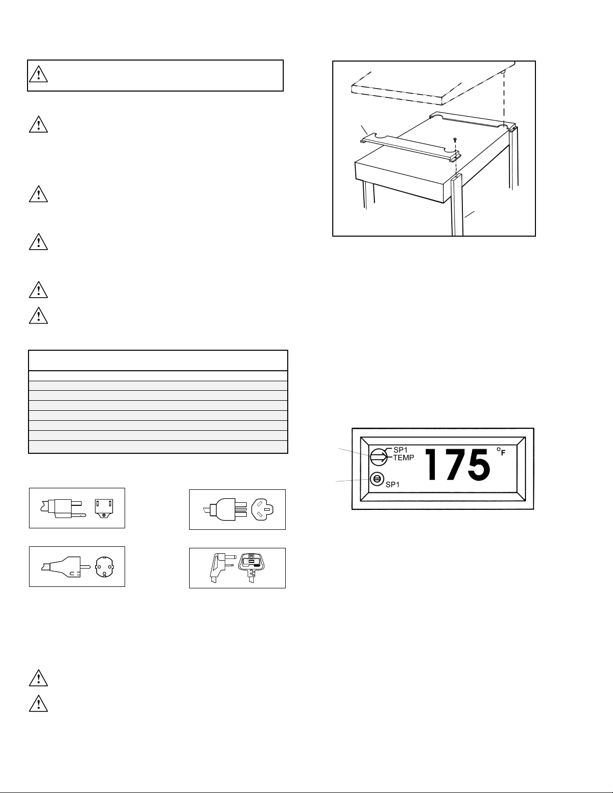
INSTALLATION OF STACKING HARDWARE (OPTIONAL)
1. Remove screws from top of Leg Covers.
2. Place stacking hardware over unit and Leg Covers as
shown (cutouts for feet must face in).
3. Reinstall Leg Cover screws through bracket, as shown.
OPERATION
1. To operate warmer, turn the master power switch to the
“ON” position.
NOTE:This unit equipped with an electronic temperature
controller; for it to function on the master on/off switch must be
in the “ON” position.
2. To set temperature, turn Mode Switch (A) counterclockwise
to the “SP-1” position.
3. Adjust Setpoint Screw (B) to 175°F. (80°C).
4. Turn Mode Switch (A) clockwise to “TEMP” position.
5. Allow 20-30 minutes for unit to heat up.
6. Place product in a preheated pan towards the front of
the unit.
NOTE: Holding temperatures and length of holding time may
vary depending on product preparation, cooking time and
internal food temperature.
MAINTENANCE
The Hatco GRCW Multi-Product Warmer requires very little
maintenance if installed and operated in accordance with the
manufacturer’s instructions.To avoid injury, turn the master
power switch off, unplug the unit from power source and allow
to cool before performing any maintenance or cleaning.
ELECTRICAL SPECIFICATIONS
Rated Plug Ship
Model Volta ge Wattage Amps Configuration Weig
ht
GRCW-J 100 517 5.2 NEMA 5-15P 42 lbs. (19 kg)
GRCW 120 535 4.5 NEMA 5-15P 42 lbs. (19 kg)
GRCW-EX 220 473 2.2 CEE 7/7 SCHUKO 42 lbs. (19 kg)
GRCW-IS 220 473 2.2 CEE 7/7 SCHUKO 42 lbs. (19 kg)
GRCW-AUS 240 535 2.2 AS3112 42 lbs.(19 kg)
GRCW-ENG 240 535 2.2 BS 1363 42 lbs.(19 kg)
GRCW-EXCE 220-230 517 2.3 CEE 7/7 SCHUKO 42 lbs. (19 kg)
GRCW-ENGCE 230-240 535 2.2 BS 1363 42 lbs.(19 kg)
PLUG CONFIGURATIONS
NEMA 5-15P
CEE 7/7 SCHUKO
AS3112
BS 1363
A
B
STACKING
HARDWARE
HATCO MODEL GRCW
OTHER MULTI-PRODUCT WARMER
LEG
COVER
Page 3

CLEANING
To preser ve the finish of your unit, it is recommended that the
it be cleaned daily.To clean warmer, use soft cloth. Stubborn
stains may be removed with a NON-ABRASIVE, mild cleaning
agent or a stainless steel cleaner on metal parts.
Use only NON-ABRASIVE CLEANERS. Abrasive
cleaners will scratch the surfaces, marring its
appearance, making it susceptible to soil accumulation and
reducing the performance.
Wipe off the polycarbonate rear and side doors using a soft,
clean, damp cloth. DO NOT USE GLASS CLEANER. Glass
cleaner may scratch the polycarbonate surface.
DISPLAY LIGHT BULB REPLACEMENT - The only userreplacement item is the coated light bulb located in the upper
heating unit.These bulbs have a special coating to guard
against injury and food contamination in the event of breakage.
To replace a light bulb, disconnect the power supply and
wait until the unit has cooled. Unscrew the light bulb from
the unit and replace it with a new specially coated
incandescent bulb.
Model GRCW
NOTE:Hatco shatter-resistant light bulbs meet N.S.F.standards
for food holding and display areas.
Only bulbs which meet or exceed N.S.F. standards,
specifically designed for food holding areas may be
used. Breakage of bulbs not specially coated could result in
personal injury and/or food contamination.
SERVICE
If service is required on this unit, contact your authorized
service agent, or contact the Hatco Service Depar tment at
800-558-0607 or 414-671-6350; fax 800-690-2966 or
international fax 414-671-3976.
TROUBLE SHOOTING GUIDE – MULTI-PRODUCT WARMER
1. No heat and no light: A. Check power supply and circuit breaker.
B. Check plug and receptacle.
2. Heat, but no light: A. Replace bulb(s) with approved 60 watt lamp.
3. Product not hot enough: A. Check controller temperature reading. If less than 175°F (80°C), check Set Point
by turning Mode Switch counter clockwise to SP-1. Use SP-1 set screw to adjust
temperature if necessary.
B. If temperature is set at desired level, check relay and blanket heater.
NOTE:Control probe must be attached to foil blanket heater.
C. If controller does not display Set Point or temperature, check transformer
and controller.
D. If base is operating properly, check (1) overhead heater, (2) air velocity in open front
area and redirect air flow or move appliance, (3) check product temperature at start of
15 minute test period. Food product should be 190°F (88°C) or higher at start.
Condition: Check:
WARNING
Hatco replacement parts are specified to operate safely in the environments in which they are used. Some aftermarket
or generic replacement parts do not have the characteristics that will allow them to operate safely in Hatco equipment.
It is essential to use Hatco replacement parts when repairing Hatco equipment. Failure to use Hatco replacement parts
may subject operators of the equipment to hazardous electrical voltage, resulting in electrical shock or burn.
Page 4

HATCO CORPORATION
P.O. Box 340500, Milwaukee, WI 53234-0500 U.S.A.
(800) 558-0607 (414) 671-6350 Parts & Service Fax (800) 690-2966 Int’l. Fax (414) 671-3976
Web Site: www.hatcocorp.com
P/N 07.04.296.00 Form No.GRCWM-0500Printed in U.S.A.
REPLACEMENT PARTS LIST
1 Element Guard 04.08.030.00 1
2 Light Socket 02.30.044.00 1
3 Hardcoat Chute 04.15.323.00 1
4 Pan Stops 05.04.150.00 2
5A Acrylic Side Doors AS.12.004.00 2
5B Hinge Bracket - Right Hand Side 04.14.325.00 2
§
Hinge Bracket - Left Hand Side 04.15.326.00 2
§
6A Acrylic Rear Door AS.12.005.00 1
6B Hinge Bracket - Right Hand Rear 04.14.340.00 1
§
Hinge Bracket - Left Hand Rear 04.15.341.00 1
§
7 Support Covers 04.15.331.00 4
8 Rubber Foot - Complete R05.30.029.00 4
9 Switch Compartment Cover 04.15.338.00 1
10 Control Compartment Cover 04.15.337.00 1
11 Stacking Hardware 04.15.345.00 2
12A High-Temp Plastic Pan - ½ Size 04.09.225.00 3
12B High-Temp Plastic Pan - ¼ Size 04.09.227.00 6
§
13A Plastic Pan Cover - ½ Size 04.09.226.00 3*
13B Plastic Pan Cover - ¼ Size 04.09.233.00 6§ *
14A Wire Trivet - ½ Size 04.09.224.00 3^
14B Wire Trivet - ¼ Size 04.09.228.00 6§ ^
15 24 Volt Relay R02.01.050.00 1
Shaded area reflects export models only. * Pans with Wire Trivet do not include covers. ^ Wire Trivets not included in pans with covers.§Not shown
ITEM DESCRIPTION PART NO. QTY. ITEM DESCRIPTION PART NO. QTY.
PARTS COMMON TO ALL GRCW’S
PARTS SPECIFIC TO GRCW SERIES BY VOLTAGE
ITEM DESCRIPTION GRCW-J GRCW GRCW-EX & GRCW-ENG GRCW-AUS GRCW-EXCE GRCW-ENGCE
GRCW-IS
100V 120V 220V 240V 240V 220-230V 230-240V
16 Temp.Controller/Displ. R02.01.062.00 R02.01.049.00 R02.01.062.00 R02.01.062.00 R02.01.062.00 R02.01.062.00 R02.01.062.00
17 Temerature Probe 02.01.078.00 02.01.056.00 02.01.078.00 02.01.078.00 02.01.078.00 02.01.078.00 02.01.078.00
18 On/Off Toggle Switch 02.19.016.00 02.19.016.00 02.19.008A.00 02.19.008A.00 02.19.008A.00 02.19.008A.00 02.19.008A.00
19 Indicator Light 02.19.154.00 02.19.154.00 02.19.151.00 02.19.151.00 02.19.151.00 02.19.150.00 02.19.150.00
20 Overhead Heating Element R02.08.402.00 R02.08.400.00 R02.08.401.00 R02.08.401.00 R02.08.401.00 R02.08.401.00 R02.08.401.00
21 Coated Light Bulb 02.30.043.00 02.30.043.00 02.30.058.00 02.30.058.00 02.30.058.00 02.30.058.00 02.30.058.00
22 Base Blanket Element 02.05.271.00 02.05.204.00 02.05.224.00 02.05.264.00 02.05.264.00 02.05.224.00 02.05.264.00
23 Power Cord w/Plug 02.18.030.00 02.18.030.00 02.18.077.00 02.18.066.00 02.18.104.00 02.18.077.00 02.18.066.00
24 Cord Grip (plastic)
§
02.20.206.00 02.20.206.00 02.20.212.00 02.20.212.00 02.20.212.00 02.20.212.00 02.20.212.00
25 24 Volt Transformer 02.17.022.00 02.17.022.00 02.17.023.00 02.17.023.00 02.17.023.00 02.17.035.00 02.17.035.00
26 Terminal Block
§
— — — — — 02.15.030.00 02.15.030.00
27 Rubber Boot/Toggle Switch
§
— — — — — 02.20.040.00 02.20.040.00
Electrical Drawing HS1-3287 HS1-1722 HS1-2328 HS1-2721 HS1-3776 HS1-4172 HS1-4173
3
2
12A
1
11
4
5A
9
16
23
22
19
21
20
14A
15
13A
25
18
10
6A
7
8
17
 Loading...