

Page 1
Register Online!
www.hatcocorp.com
WARNING
ADVERTENCIA
AVERTISSEMENT
(see page 2)
Installation and Operating Manual
®
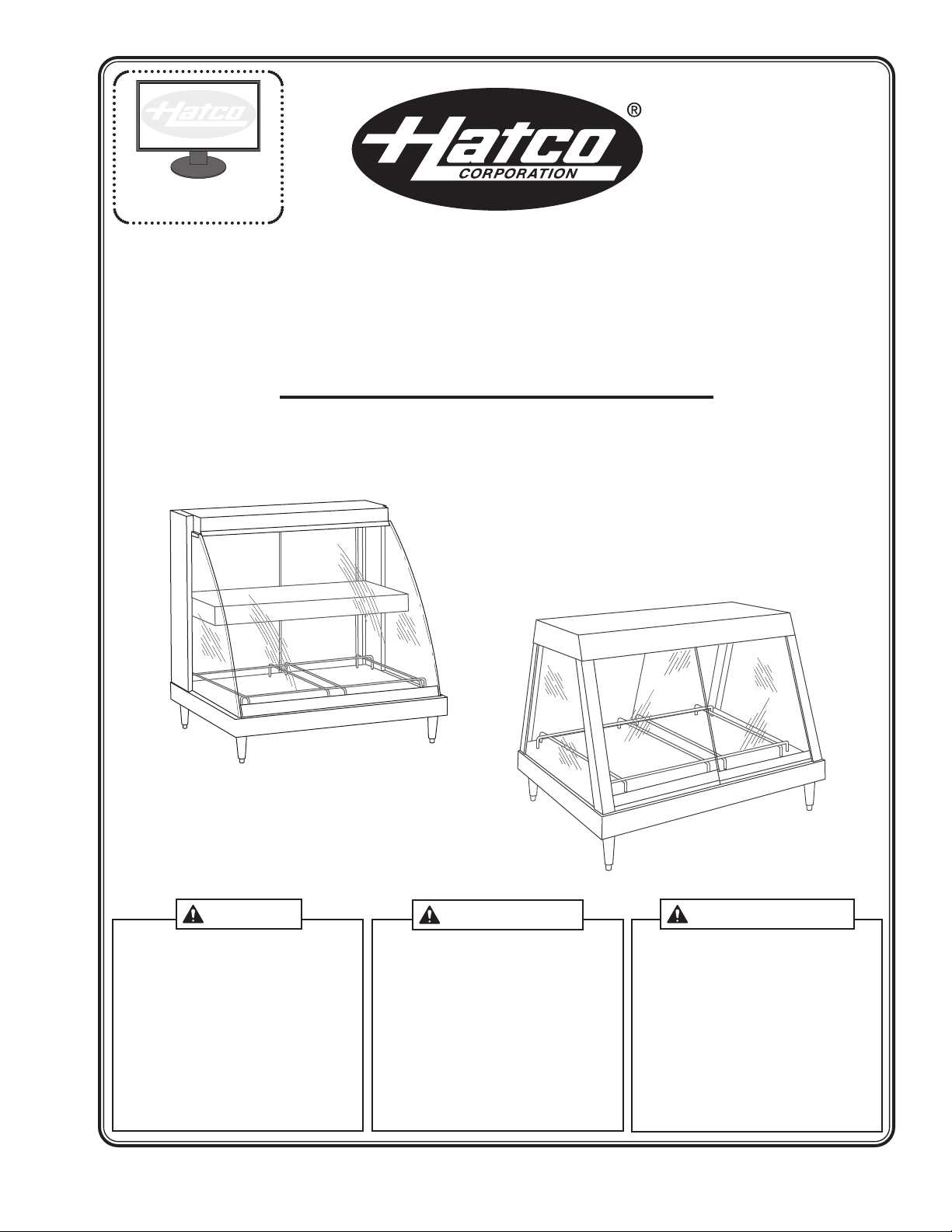
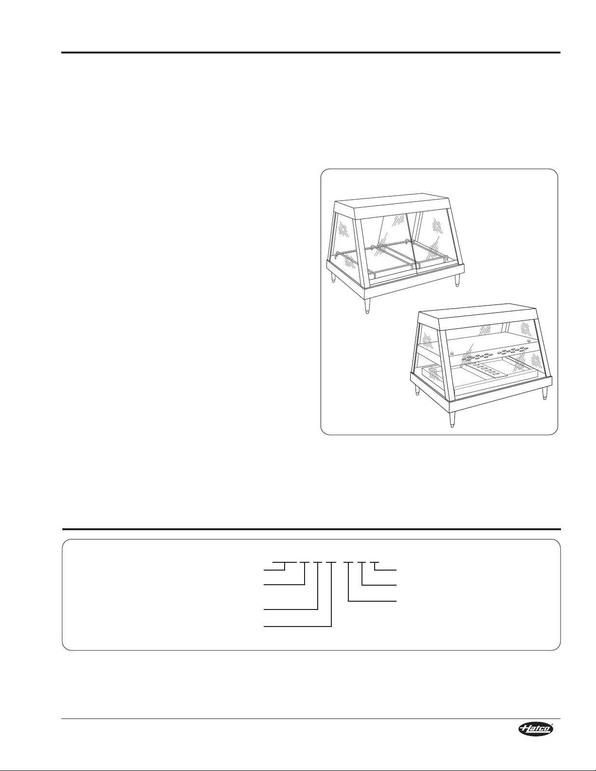
GLO-RAY
Heated Display Cases
GRCD and GRHD Series
P/N 07.04.275.00
Do not operate this equipment unless you
have read and understood the contents of
this manual! Failure to follow the
instructions contained in this manual may
result in serious injury or death. This
manual contains important safety
information concerning the maintenance,
use, and operation of this product. If
you’re unable to understand the contents
of this manual, please bring it to the
attention of your supervisor. Keep this
manual in a safe location for future
reference.
No opere este equipo al menos que haya
leído y comprendido el contenido de este
manual! Cualquier falla en el seguimiento
de las instrucciones contenidas en este
manual puede resultar en un serio lesión
o muerte. Este manual contiene
importante información sobre seguridad
concerniente al mantenimiento, uso y
operación de este producto. Si usted no
puede entender el contenido de este
manual por favor pregunte a su
supervisor. Almacenar este manual en
una localización segura para la referencia
futura.
Ne pas utiliser cet équipement sans avoir
lu et compris le contenu de ce manuel !
Le non-respect des instructions
contenues dans ce manuel peut entraîner
de graves blessures ou la mort. Ce
manuel contient des informations
importantes concernant l'entretien,
l'utilisation et le fonctionnement de ce
produit. Si vous ne comprenez pas le
contenu de ce manuel, veuillez le signaler
à votre supérieur. Conservez ce manuel
dans un endroit sûr pour pouvoir vous y
référer plus tard.
© 2012 Hatco Corporation
Page 2
CONTENTS
NOTICE
CAUTION
WARNING
24 Hour 7 Day Parts and Service
Assistance available in the United States
and Canada by calling (800) 558-0607.
Important Owner Information ..............................................2
Introduction...........................................................................2
Important Safety Information...............................................3
Model Description.................................................................4
Model Designation................................................................5
Specifications........................................................................6
Plug Configurations ............................................................6
Electrical Rating Chart — GRCD Models ...........................6
Electrical Rating Chart — GRHD Models ...........................8
Dimensions — GRCD Series ...........................................10
Dimensions — GRHD Series............................................11
Installation...........................................................................12
General.............................................................................12
Assembling GRCD Models...............................................12
Assembling GRHD Models...............................................13
IMPORTANT OWNER INFORMATION
Record the model number, serial number (specification label
located on the back of the unit), voltage, and purchase date of
the unit in the spaces below. Please have this information
available when calling Hatco for service assistance.
Model No. ________________________________________
Serial No. ________________________________________
Voltage __________________________________________
Date of Purchase __________________________________
Register your unit!
Completing online warranty registration will prevent delay in
obtaining warranty coverage. Access the Hatco website at
www.hatcocorp.com, select the Parts & Service pull-down
menu, and click on “Warranty Registration”.
Operation.............................................................................14
General.............................................................................14
Maintenance ........................................................................15
General.............................................................................15
Daily Cleaning ..................................................................15
Removing Lime and Mineral Deposits..............................15
Replacing Display Light Bulbs ..........................................15
Replacing a Fuse..............................................................16
Troubleshooting Guide ......................................................17
Options and Accessories...................................................18
Limited Warranty.................................................................19
Authorized Parts Distributors............................Back Cover
Business 8:00
Hours: Central Standard Time (C.S.T.)
Telephone: (800) 558-0607; (414) 671-6350
E-mail: partsandservice@hatcocorp.com
Fax: (800) 690-2966 (Parts and Service)
Additional information can be found by visiting our web site at
www.hatcocorp.com.
AM to 5:00 PM
(Summer Hours: June to September –
8:00
AM to 5:00 PM C.S.T.
Monday through Thursday
8:00
AM to 2:30 PM C.S.T. Friday)
(414) 671-3976 (International)
INTRODUCTION
®
Hatco Glo-Ray
prepared foods for prolonged periods of time while maintaining
that “just made” quality. Hatco Display Cases provide the best
environment for food products by regulating the air temperature.
Display models equipped with humidity control also balance the
humidity level. The use of controlled heat maintains serving
temperature and texture longer than conventional holding
equipment.
Hatco Glo-Ray Heated Display Cases are products of extensive
research and field testing. The materials used were selected for
maximum durability, attractive appearance, and optimum
performance. Every unit is inspected and tested thoroughly prior
to shipment.
This manual provides the installation, safety, and operating
instructions for Hatco Glo-Ray Heated Display Cases. Hatco
recommends all installation, operating, and safety instructions
appearing in this manual be read prior to installation or
operation of a unit.
Heated Display Cases are designed to hold
Safety information that appears in this manual is identified by
the following signal word panels:
WARNING indicates a hazardous situation which, if not
avoided, could result in death or serious injury.
CAUTION indicates a hazardous situation which, if not
avoided, could result in minor or moderate injury.
NOTICE is used to address practices not related to
personal injury.
2
Form No. GRCDHDM-0712
Page 3
IMPORTANT SAFETY INFORMATION
WARNING
NOTICE
CAUTION
WARNING
Read the following important safety information before using this equipment to avoid serious
injury or death and to avoid damage to equipment or property.
ELECTRIC SHOCK HAZARD:
• Plug unit into a properly grounded electrical receptacle
of the correct voltage, size, and plug configuration. If
plug and receptacle do not match, contact a qualified
electrician to determine and install the proper voltage
and size electrical receptacle.
• Turn OFF power switch, unplug power cord, and allow
unit to cool before performing any cleaning,
adjustments, or maintenance.
• Unit is not weatherproof. Locate unit indoors where
ambient air temperature is a minimum of 70°F (21°C).
• DO NOT submerge or saturate with water. Unit is not
waterproof. Do not operate if unit has been submerged
or saturated with water.
• Do not steam clean or use excessive water on unit.
• This unit is not “jet-proof” construction. Do not use jetclean spray to clean this unit.
• Do not pull unit by power cord.
• Discontinue use if power cord is frayed or worn.
• Do not attempt to repair or replace a damaged power
cord. The cord must be replaced by Hatco, an
Authorized Hatco Service Agent, or a person with
similar qualifications.
• This unit must be serviced by qualified personnel only.
Service by unqualified personnel may lead to electric
shock or burn.
• Use only Genuine Hatco Replacement Parts when
service is required. Failure to use Genuine Hatco
Replacement Parts will void all warranties and may
subject operators of the equipment to hazardous
electrical voltage, resulting in electrical shock or burn.
Genuine Hatco Replacement Parts are specified to
operate safely in the environments in which they are
used. Some aftermarket or generic replacement parts
do not have the characteristics that will allow them to
operate safely in Hatco equipment.
FIRE HAZARD: Locate unit a minimum of 1″ (25 mm) from
combustible walls and materials. If safe distances are not
maintained, discoloration or combustion could occur.
EXPLOSION HAZARD: Do not store or use gasoline or
other flammable vapors or liquids in the vicinity of this or
any other appliance.
Make sure food product has been heated to the proper
food-safe temperature before placing in unit. Failure to
heat food product properly may result in serious health
risks. This unit is for holding pre-heated food product only.
Hatco Corporation is not responsible for actual food
product serving temperature. It is the responsibility of the
user to ensure that food product is held and served at a
safe temperature.
Use only light bulbs that meet or exceed National
Sanitation Foundation (NSF) standards and are specifically
designed for food holding areas. Breakage of light bulbs
not specially coated could result in personal injury and/or
food contamination.
Form No. GRCDHDM-0712
Do not place food product directly onto shelves. Food
product must be wrapped, boxed, or on a food pan.
Make sure all operators have been instructed on the safe
and proper use of the unit.
This unit is not intended for use by children or persons
with reduced physical, sensory, or mental capabilities.
Ensure proper supervision of children and keep them away
from the unit.
This unit has no “user-serviceable” parts. If service is
required on this unit, contact an Authorized Hatco Service
Agent or contact the Hatco Service Department at
800-558-0607 or 414-671-6350; fax 800-690-2966; or
International fax 414-671-3976.
BURN HAZARD:
• Some exterior surfaces on unit will get hot. Use caution
when touching these areas.
• Hot water in unit may cause scalding injury. Allow unit
to cool before draining or cleaning.
Locate unit at proper counter height in an area that is
convenient for use. Location should be level to prevent unit
or its contents from falling accidentally and strong enough
to support weight of unit and contents.
The National Sanitation Foundation (NSF) requires that
units over 36″ (914 mm) in width or weighing more than 80
lbs. (36 kg) either be sealed to or raised above the
installation surface. If unit cannot be sealed at the point of
use, 4″ (102 mm) legs are included to allow for proper
cleaning access below unit.
Do not lay unit on the side with control panel or on front of
a curved glass unit. Damage to unit could occur.
Do not drag or slide unit when moving or installing.
Carefully lift unit to prevent the rubber feet from tearing off.
Use non-abrasive cleaners and cloths only. Abrasive
cleaners and cloths could scratch finish of unit, marring
its appearance and making it susceptible to soil
accumulation.
Use of distilled water in the water reservoir of humidified
units is recommended to preserve the life of electrical and
mechanical components. If non-distilled water is used, the
reservoir will require periodic cleaning and deliming (refer
to the MAINTENANCE section for cleaning procedure). Unit
failure due to lime or mineral deposits is not covered under
warranty.
Clean unit daily to avoid malfunctions and maintain
sanitary operation.
3
Page 4
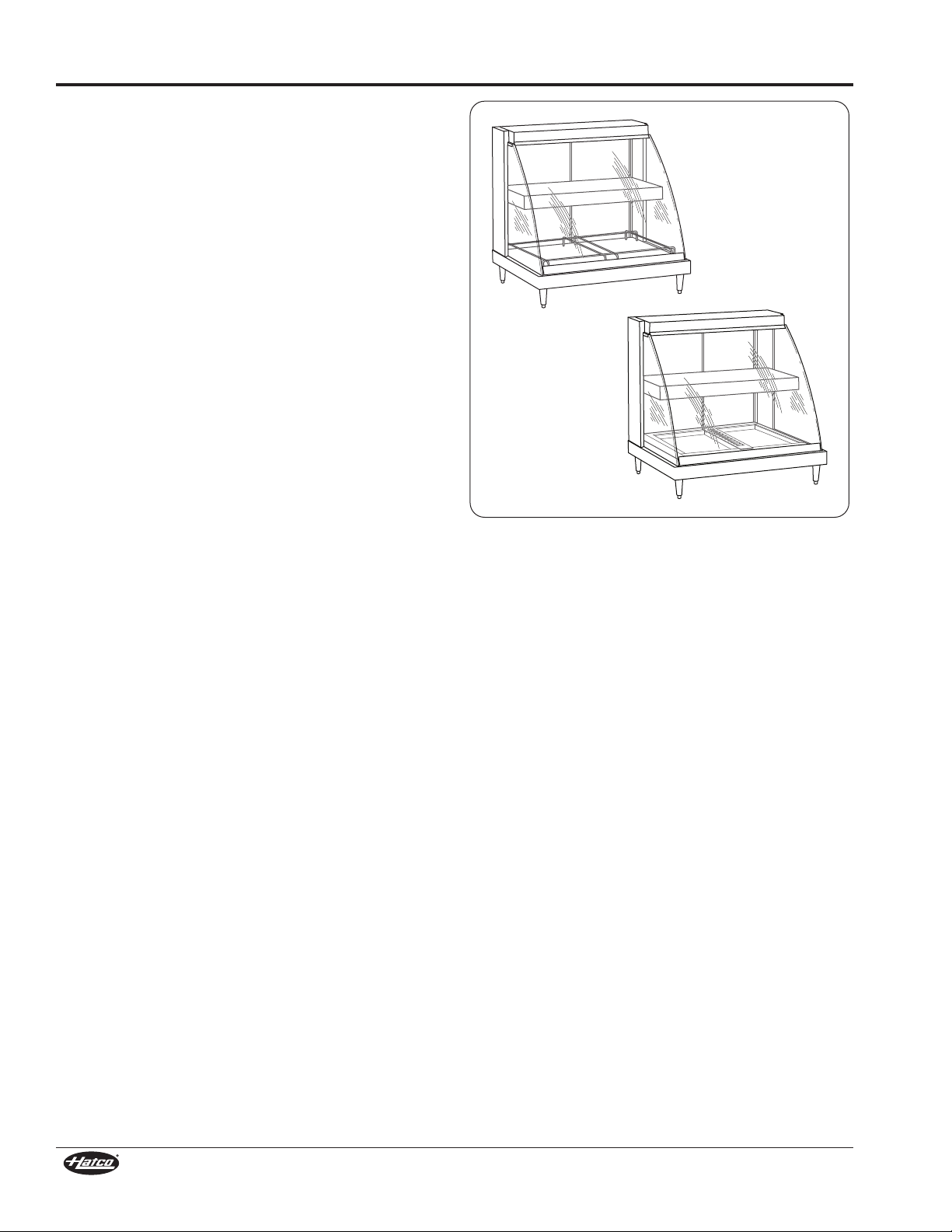
GRCDH-2PD
GRCD-2PD
MODEL DESCRIPTION
All GRCD Models
All GRCD Heated Display Cases are constructed of stainless
steel and aluminum with a tempered, curved front glass panel,
hinged or sliding rear glass doors, and glass side panels. The
display cases feature a thermostatically-controlled heated base,
infrared overhead heating elements, incandescent display
lights, 4″ (102 mm) adjustable legs, and a 6′ (1829 mm) cord
and plug set.
Options and accessories available include pan skirts, halogen
display lights, sign holders, mirrored glass sliding doors, and
flip-up front doors. Refer to the OPTIONS ANDACCESSORIES
section for details.
Model GRCD-1P
The GRCD-1P is designed to hold one standard full size food
pan. The unit has one hinged rear door.
Model GRCD-1PD
The GRCD-1PD is designed to hold up one standard full size
food pan on the bottom shelf and one standard 1/2-size or two
1/3-size food pans on the top stainless steel shelf. The unit has
one hinged rear door.
Model GRCD-2P
The GRCD-2P is designed to hold up to two standard full size
food pans. The unit has two sliding rear doors.
Model GRCD-2PD
The GRCD-2PD is designed to hold up to two standard full size
food pans on the bottom shelf and one standard full size plus a
1/3-size food pan on the top stainless steel shelf. The unit has
two sliding rear doors.
Model GRCD-3P
The GRCD-3P is designed to hold up to three standard full size
food pans. The unit has two sliding rear doors.
Model GRCD-3PD
The GRCD-3PD is designed to hold up to three standard full
sized food pans on the bottom shelf and two standard full size
food pans on the top stainless steel shelf. The unit has two
sliding rear doors.
GRCDH Series
The GRCDH series (Humidified) is similar to the GRCD series
(Non-Humidified), but come equipped with a thermostaticallycontrolled, adjustable humidity system. A 3 quart (2.8 liter)
capacity heated water reservoir in the base provides humidity to
extend food holding time up to four hours.
GRCDH models are available in one, two, or three pan sizes
and with single or dual shelves.
NOTE: GRCD models cannot be converted to GRCDH models.
GRCD Models
4
Form No. GRCDHDM-0712
Page 5
MODEL DESCRIPTION
GRHDH-2PD
GRHD-2P
G R X D X- X P D
Glo-Ray
®
C = Curved
H = Heated
Display
No Character = Non-Humidified
H = Humidified
Pan
Dual Shelf
Full Size Pan Capacity
on Bottom Shelf
All GRHD Models
All GRHD Heated Display Cases are constructed of stainless
steel and aluminum with rear glass sliding doors and full-view
tempered glass on the front and sides. The display cases
feature a thermostatically-controlled heated base, infrared
overhead heating elements, incandescent display lights,
4″ (102 mm) adjustable legs, and a 6′ (1829 mm) cord and plug
set.
Options and accessories available include pan skirts, halogen
display lights, sign holders, mirrored glass sliding doors, flip-up
doors, and a slant leg kit. Refer to the OPTIONS AND
ACCESSORIES section for details.
Model GRHD-2P
The GRHD-2P is designed to hold up to two standard full size
food pans.
Model GRHD-2PD
The GRHD-2PD is designed to hold up to two standard full size
food pans on the bottom shelf and two standard 1/2-size food
pans on the top shelf.
Model GRHD-3P
The GRHD-3P is designed to hold up to three standard full size
food pans.
Model GRHD-3PD
The GRHD-3PD is designed to hold up to three standard full
size food pans on the bottom shelf and three standard 1/2-size
food pans on the top shelf.
Model GRHD-4P
The GRHD-4P is designed to hold up to four standard full size
food pans.
Model GRHD-4PD
The GRHD-4PD is designed to hold up to four standard full size
food pans on the bottom shelf and four standard half size food
pans or two standard full size food pans on the top shelf.
GRHDH Series
The GRHDH series (Humidified) is similar to the GRHD series
(Non-Humidified), but come equipped with a thermostatically
controlled, adjustable humidity system. A 3 or 6 quart (2.8 or
5.7 liter) capacity heated water reservoir in the base provides
humidity to extend food holding time up to four hours.
GRHDH models are available in two, three, or four pan sizes
and with single or dual shelves.
NOTE: GRHD models cannot be converted to GRHDH models.
Form No. GRCDHDM-0712
5
GRHD Models
MODEL DESIGNATION
Page 6
SPECIFICATIONS
WARNING
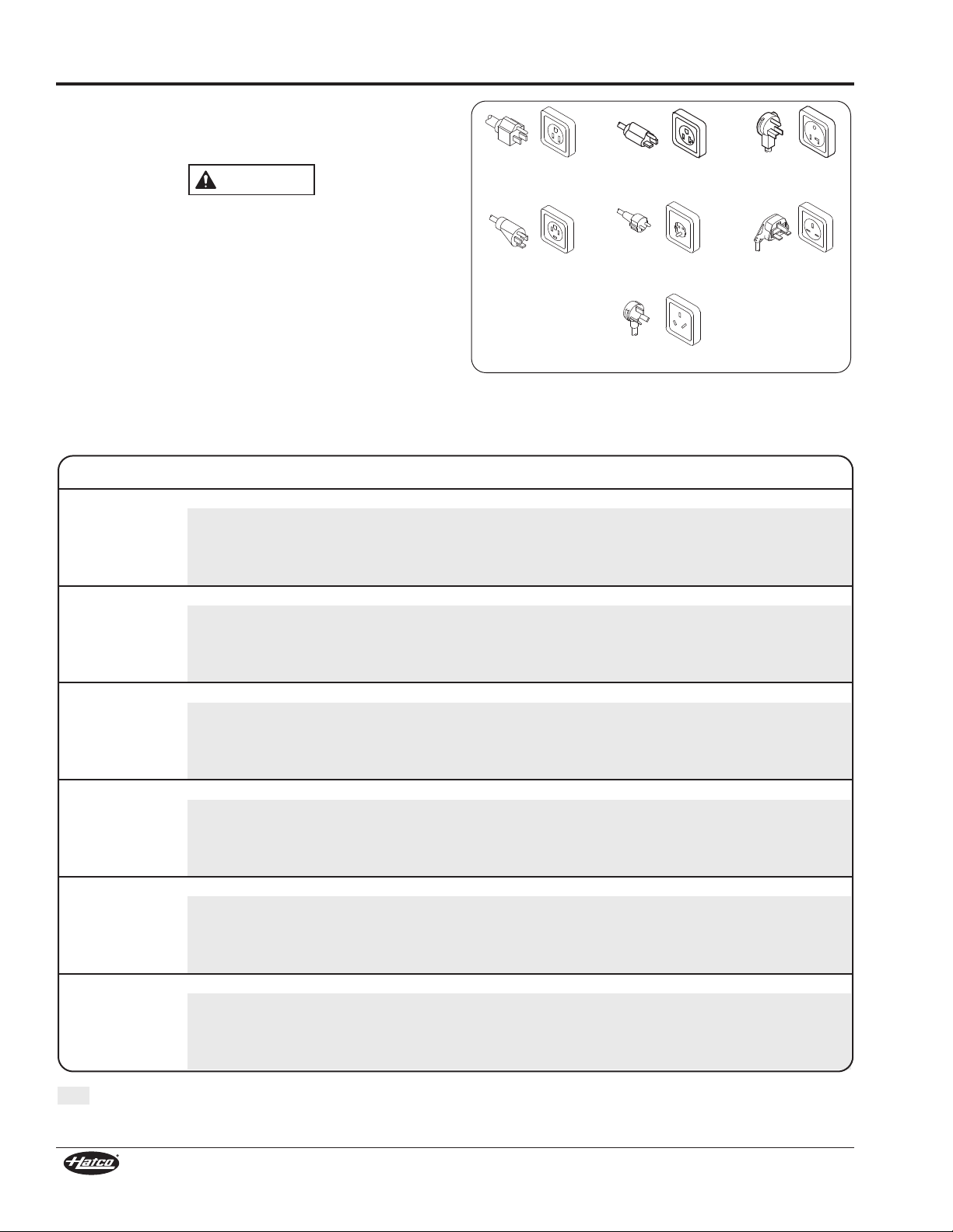
NEMA 5-15P NEMA 5-20P
CEE 7/7 Schuko
AS 3112
NEMA 5-30P
BS-1363
NEMA 14-20P
Plug Configurations
Units are supplied from the factory with an electrical cord and
plug installed. Plugs are supplied according to the application.
ELECTRIC SHOCK HAZARD: Plug unit into a properly
grounded electrical receptacle of the correct voltage, size,
and plug configuration. If plug and receptacle do not
match, contact a qualified electrician to determine and
install the proper voltage and size electrical receptacle.
NOTE: The specification label is located on the top rear of the
unit. See label for serial number and verification of unit
electrical information.
NOTE: Receptacle not supplied by Hatco.
Electrical Rating Chart — GRCD Models
Model Voltage Watts Amps Plug Configuration Shipping Weight
GRCD-1P 120 410 3.4 NEMA 5-15P 95 lbs. (43 kg)
GRCD-2P 120 780 6.5 NEMA 5-15P 120 lbs. (54 kg)
GRCD-3P 120 1005 8.4 NEMA 5-15P 152 lbs. (69 kg)
GRCD-1PD 120 860 7.2 NEMA 5-15P 98 lbs. (45 kg)
GRCD-2PD 120 1210 10.1 NEMA 5-15P 170 lbs. (77 kg)
GRCD-3PD 120 1710 14.3 NEMA 5-15P* 210 lbs. (95 kg)
Plug Configurations
220 405 1.8 CEE 7/7 Schuko or BS-1363 95 lbs. (43 kg)
240 425 1.8 CEE 7/7 Schuko or AS 3112 95 lbs. (43 kg)
220–230 (CE) 443 1.9 CEE 7/7 Schuko 95 lbs. (43 kg)
230–240 (CE) 425 1.8 BS-1363 95 lbs. (43 kg)
220 710 3.2 CEE 7/7 Schuko or BS-1363 120 lbs. (54 kg)
240 780 3.3 CEE 7/7 Schuko or AS 3112 120 lbs. (54 kg)
220–230 (CE) 776 3.4 CEE 7/7 Schuko 120 lbs. (54 kg)
230–240 (CE) 780 3.3 BS-1363 120 lbs. (54 kg)
220 915 4.2 CEE 7/7 Schuko or BS-1363 152 lbs. (69 kg)
240 1005 4.2 CEE 7/7 Schuko or AS 3112 152 lbs. (69 kg)
220–230 (CE) 1000 4.4 CEE 7/7 Schuko 152 lbs. (69 kg)
230–240 (CE) 1005 4.2 BS-1363 152 lbs. (69 kg)
220 907 4.1 CEE 7/7 Schuko or BS-1363 98 lbs. (45 kg)
240 905 3.8 CEE 7/7 Schuko or AS 3112 98 lbs. (45 kg)
220–230 (CE) 907–992 4.1–4.3 CEE 7/7 Schuko 98 lbs. (45 kg)
230–240 (CE) 831–905 3.6–3.8 BS-1363 98 lbs. (45 kg)
220 1080 4.9 CEE 7/7 Schuko or BS-1363 170 lbs. (77 kg)
240 1285 5.4 CEE 7/7 Schuko or AS 3112 170 lbs. (77 kg)
220–230 (CE) 1080–1180 4.9–5.1 CEE 7/7 Schuko 170 lbs. (77 kg)
230–240 (CE) 1180–1285 5.1–5.4 BS-1363 170 lbs. (77 kg)
220 1437 6.5 CEE 7/7 Schuko or BS-1363 210 lbs. (95 kg)
240 1710 7.1 CEE 7/7 Schuko or AS 3112 210 lbs. (95 kg)
220–230 (CE) 1437–1570 6.5–6.8 CEE 7/7 Schuko 210 lbs. (95 kg)
230–240 (CE) 1570–1710 6.8–7.1 BS-1363 210 lbs. (95 kg)
* NEMA 5-20P for Canada.
The shaded areas contain electrical information for International models only.
6
Form No. GRCDHDM-0712
Page 7

SPECIFICATIONS
Electrical Rating Chart — GRCDH Models
Model Voltage Watts Amps Plug Configuration Shipping Weight
GRCDH-1P 120 660 5.5 NEMA 5-15P 90 lbs. (41 kg)
220 634 2.9 CEE 7/7 Schuko or BS-1363 90 lbs. (41 kg)
240 697 2.9 CEE 7/7 Schuko or AS 3112 90 lbs. (41 kg)
220–230 (CE) 693 3.0 CEE 7/7 Schuko 90 lbs. (41 kg)
230–240 (CE) 697 2.9 BS-1363 90 lbs. (41 kg)
GRCDH-2P
GRCDH-3P
GRCDH-1PD
GRCDH-2PD 120 1460 12.2 NEMA 5-15P* 174 lbs. (79 kg)
GRCDH-3PD 120 1960 16.3 NEMA 5-20P† 220 lbs. (100 kg)
100 976 9.8 NEMA 5-15P 124 lbs. (56 kg)
120 1030 8.6 NEMA 5-15P 124 lbs. (56 kg)
220 939 4.3 CEE 7/7 Schuko or BS-1363 124 lbs. (56 kg)
240 1052 4.4 CEE 7/7 Schuko or AS 3112 124 lbs. (56 kg)
220–230 (CE) 1026 4.5 CEE 7/7 Schuko 124 lbs. (56 kg)
230–240 (CE) 1052 4.4 BS-1363 124 lbs. (56 kg)
100 1201 12.0 NEMA 5-15P 156 lbs. (71 kg)
120 1255 10.5 NEMA 5-15P 156 lbs. (71 kg)
220 1145 5.2 CEE 7/7 Schuko or BS-1363 156 lbs. (71 kg)
240 1277 5.3 CEE 7/7 Schuko or AS 3112 156 lbs. (71 kg)
220–230 (CE) 1251 5.4 CEE 7/7 Schuko 156 lbs. (71 kg)
230–240 (CE) 1277 5.3 BS-1363 156 lbs. (71 kg)
100 1038 10.4 NEMA 5-15P 120 lbs. (54 kg)
120 1110 9.3 NEMA 5-15P 120 lbs. (54 kg)
220 1136 5.2 CEE 7/7 Schuko or BS-1363 120 lbs. (54 kg)
240 1177 4.9 CEE 7/7 Schuko or AS 3112 120 lbs. (54 kg)
220–230 (CE) 1136–1242 5.2–5.4 CEE 7/7 Schuko 120 lbs. (54 kg)
230–240 (CE) 1081–1177 4.7–4.9 BS-1363 120 lbs. (54 kg)
220 1309 5.9 CEE 7/7 Schuko or BS-1363 174 lbs. (79 kg)
240 1557 6.5 CEE 7/7 Schuko or AS 3112 174 lbs. (79 kg)
220–230 (CE) 1309–1430 5.9–6.2 CEE 7/7 Schuko 174 lbs. (79 kg)
230–240 (CE) 1430–1557 6.2–6.5 BS-1363 174 lbs. (79 kg)
220 1666 7.6 CEE 7/7 Schuko or BS-1363 220 lbs. (100 kg)
240 1982 8.3 CEE 7/7 Schuko or AS 3112 220 lbs. (100 kg)
220–230 (CE) 1666–1820 7.6–7.9 CEE 7/7 Schuko 220 lbs. (100 kg)
230–240 (CE) 1820–1982 7.9–8.3 BS-1363 220 lbs. (100 kg)
The shaded areas contain electrical information for International models only.
* NEMA 5-20P for Canada.
† NEMA 5-30P for Canada. Not available for Canada with Backlit Base Sign Holder.
Form No. GRCDHDM-0712
7
Page 8

SPECIFICATIONS
Electrical Rating Chart — GRHD Models
Model Voltage Watts Amps Plug Configuration Shipping Weight
GRHD-2P 120 940 7.8 NEMA 5-15P 120 lbs. (54 kg)
220 1035 4.7 CEE 7/7 Schuko or BS-1363 120 lbs. (54 kg)
240 940 3.9 CEE 7/7 Schuko or AS 3112 120 lbs. (54 kg)
220–230 (CE) 1131 4.9 CEE 7/7 Schuko 120 lbs. (54 kg)
230–240 (CE) 940 3.9 BS-1363 120 lbs. (54 kg)
GRHD-3P 120 1350 11.3 NEMA 5-15P 143 lbs. (65 kg)
220 1465 6.7 CEE 7/7 Schuko or BS-1363 143 lbs. (65 kg)
240 1350 5.6 CEE 7/7 Schuko or AS 3112 143 lbs. (65 kg)
220–230 (CE) 1601 7.0 CEE 7/7 Schuko 143 lbs. (65 kg)
230–240 (CE) 1350 5.6 BS-1363 143 lbs. (65 kg)
GRHD-4P 120 1785 14.9 NEMA 5-20P 215 lbs. (98 kg)
120/208 1785 7.7 NEMA 14-20P 215 lbs. (98 kg)
120/240 1785 7.7 NEMA 14-20P 215 lbs. (98 kg)
220 1930 8.8 CEE 7/7 Schuko or BS-1363 215 lbs. (98 kg)
240 1785 7.4 CEE 7/7 Schuko or AS 3112 215 lbs. (98 kg)
220–230 (CE) 2109 9.2 CEE 7/7 Schuko 215 lbs. (98 kg)
230–240 (CE) 1785 7.4 BS-1363 215 lbs. (98 kg)
GRHD-2PD 120 1310 10.9 NEMA 5-15P 150 lbs. (68 kg)
220 1223 5.6 CEE 7/7 Schuko or BS-1363 150 lbs. (68 kg)
240 1310 5.5 CEE 7/7 Schuko or AS 3112 150 lbs. (68 kg)
220–230 (CE) 1220–1333 5.6–5.8 CEE 7/7 Schuko 150 lbs. (68 kg)
230–240 (CE) 1203–1310 5.2–5.5 BS-1363 150 lbs. (68 kg)
GRHD-3PD 120 1755 14.6 NEMA 5-20P 188 lbs. (85 kg)
220 1603 7.3 CEE 7/7 Schuko or BS-1363 188 lbs. (85 kg)
240 1755 7.3 CEE 7/7 Schuko or AS 3112 188 lbs. (85 kg)
220–230 (CE) 1603–1753 7.3–7.6 CEE 7/7 Schuko 188 lbs. (85 kg)
230–240 (CE) 1612–1755 7.0–7.3 BS-1363 188 lbs. (85 kg)
GRHD-4PD 120 2480 20.7 NEMA 5-30P 230 lbs. (104 kg)
120/208 2480 11.9 NEMA 14-20P 230 lbs. (104 kg)
120/240 2480 11.9 NEMA 14-20P 230 lbs. (104 kg)
220 2288 10.4 CEE 7/7 Schuko or BS-1363 230 lbs. (104 kg)
240 2480 10.3 CEE 7/7 Schuko or AS 3112 230 lbs. (104 kg)
220–230 (CE) 2288–2501 10.4–10.9 CEE 7/7 Schuko 230 lbs. (104 kg)
230–240 (CE) 2278–2480 9.9–10.3 BS-1363 230 lbs. (104 kg)
The shaded areas contain electrical information for International models only.
8
Form No. GRCDHDM-0712
Page 9

SPECIFICATIONS
Electrical Rating Chart — GRHDH Models
Model Voltage Watts Amps Plug Configuration Shipping Weight
GRHDH-2P 120 1190 9.9 NEMA 5-15P 125 lbs. (57 kg)
220 1179 5.4 CEE 7/7 Schuko or BS-1363 125 lbs. (57 kg)
240 1212 5.0 CEE 7/7 Schuko or AS 3112 125 lbs. (57 kg)
220–230 (CE) 1289 5.6 CEE 7/7 Schuko 125 lbs. (57 kg)
230–240 (CE) 1212 5.0 BS-1363 125 lbs. (57 kg)
GRHDH-3P 120 1600 13.3 NEMA 5-15P* 162 lbs. (73 kg)
220 1584 7.2 CEE 7/7 Schuko or BS-1363 162 lbs. (73 kg)
240 1622 6.8 CEE 7/7 Schuko or AS 3112 162 lbs. (73 kg)
220–230 (CE) 1731 7.5 CEE 7/7 Schuko 162 lbs. (73 kg)
230–240 (CE) 1622 6.8 BS-1363 162 lbs. (73 kg)
GRHDH-4P 120 2285 19.0 NEMA 5-20P 215 lbs. (98 kg)
120/208 2285 9.8 NEMA 14-20P 215 lbs. (98 kg)
120/240 2285 9.8 NEMA 14-20P 215 lbs. (98 kg)
220 2253 10.2 CEE 7/7 Schuko or BS-1363 215 lbs. (98 kg)
240 2329 9.7 CEE 7/7 Schuko or AS 3112 215 lbs. (98 kg)
220–230 (CE) 2463 10.7 CEE 7/7 Schuko 215 lbs. (98 kg)
230–240 (CE) 2329 9.7 BS-1363 215 lbs. (98 kg)
GRHDH-2PD 120 1560 13.0 NEMA 5-15P* 175 lbs. (79 kg)
220 1532 7.0 CEE 7/7 Schuko or BS-1363 175 lbs. (79 kg)
240 1582 6.6 CEE 7/7 Schuko or AS 3112 175 lbs. (79 kg)
220–230 (CE) 1532–1671 7.0–7.3 CEE 7/7 Schuko 175 lbs. (79 kg)
230–240 (CE) 1453–1582 6.3–6.6 BS-1363 175 lbs. (79 kg)
GRHDH-3PD 120 2005 16.7 NEMA 5-20P♦ 188 lbs. (85 kg)
220 1962 8.9 CEE 7/7 Schuko or BS-1363 188 lbs. (85 kg)
240 2027 8.4 CEE 7/7 Schuko or AS 3112 188 lbs. (85 kg)
220–230 (CE) 1962–2145 8.9–9.3 CEE 7/7 Schuko 188 lbs. (85 kg)
230–240 (CE) 1862–2027 8.1–8.4 BS-1363 188 lbs. (85 kg)
GRHDH-4PD 120 2980 24.8 NEMA 5-30P 240 lbs. (109 kg)
120/208 2980 12.9 NEMA 14-20P 240 lbs. (109 kg)
120/240 2980 12.9 NEMA 14-20P 240 lbs. (109 kg)
220 2941 13.4 CEE 7/7 Schuko or BS-1363 240 lbs. (109 kg)
240 3024 12.6 CEE 7/7 Schuko or AS 3112 240 lbs. (109 kg)
220–230 (CE) 2941–3214 13.4–14.0 CEE 7/7 Schuko 240 lbs. (109 kg)
230–240 (CE) 2777–3204 12.1–12.6 BS-1363 240 lbs. (109 kg)
The shaded areas contain electrical information for International models only.
* NEMA 5-20P for Canada.
♦ NEMA 5-30P for Canada.
Not available for Canada.
Form No. GRCDHDM-0712
9
Page 10

SPECIFICATIONS
A
F
C
Front View Side View
12-1/8″
(308 mm)
B
D E
Front View Side View
8″
(203 mm)
6-3/4″
(172 mm)
C
A
F
B
D E
Dimensions — GRCD Series
Model Width
GRCD-1P
and
GRCDH-1P
GRCD-2P
and
GRCDH-2P
GRCD-3P
and
GRCDH-3P
GRCD-1PD
and
GRCDH-1PD
GRCD-2PD
and
GRCDH-2PD
GRCD-3PD
and
GRCDH-3PD
(524 mm)
(826 mm)
(1156 mm)
(524 mm)
(826 mm)
(1156 mm)
(A)
20-5/8″
32-1/2″
45-1/2″
20-5/8″
32-1/2″
45-1/2″
Depth
(B)
26″
(660 mm)
26″
(660 mm)
26″
(660 mm)
26″
(660 mm)
26″
(660 mm)
26″
(660 mm)
Height
(C)
24″
(610 mm)
24″
(610 mm)
24″
(610 mm)
31-3/4″
(807 mm)
31-3/4″
(807 mm)
31-3/4″
(807 mm)
Footprint
Width (D)
18-1/8″
(461 mm)
30-1/2″
(775 mm)
43-1/2″
(1105 mm)
18-1/8″
(461 mm)
30-1/2″
(775 mm)
43-1/2″
(1105 mm)
Footprint
Depth (E)
24″
(610 mm)
24″
(610 mm)
24″
(610 mm)
24″
(610 mm)
24″
(610 mm)
24″
(610 mm)
Heated Shelf
Width (F)
18-1/8″
(460 mm)
30″
(762 mm)
43″
(1092 mm)
18-1/8″
(460 mm)
30″
(762 mm)
43″
(1092 mm)
Single Shelf GRCD Dimensions
NOTE: On single shelf units, the interior height dimension without the pan enclosure installed is 14-1/8″ (359 mm).
NOTE: On dual shelf units, the lower shelf interior height dimension without the pan enclosure installed is 10-1/4″ (260 mm). The
NOTE: On dual shelf units, the interior usable space dimension for the upper shelf is as follows:
upper shelf interior height dimension without the pan enclosure installed is 9″ (229 mm).
• 15″ (381 mm) deep
• 18″ (457 mm) wide for -1PD model
• 30″ (762 mm) wide for -2PD models
• 43″ (1092 mm) wide for -3PD models
10
Dual Shelf GRCD Dimensions
Form No. GRCDHDM-0712
Page 11

Dimensions—GRHD Series
Side View
12-1/8″
(308 mm)
12-1/8″
(308 mm)
Front View
A
F
B
C
D D
Side View
8″
(203 mm)
6-3/4″
(172 mm)
8″
(203 mm)
6-3/4″
(172 mm)
Front View
A
F
B
C
D
D
SPECIFICATIONS
Model
GRHD-2P
and
GRHDH-2P
GRHD-3P
and
GRHDH-3P
GRHD-4P
and
GRHDH-4P
GRHD-2PD
and
GRHDH-2PD
GRHD-3PD
and
GRHDH-3PD
GRHD-4PD
and
GRHDH-4PD
Width
(A)
32-1/2″
(826 mm)
45-1/2″
(1156 mm)
58-1/2″
(1486 mm)
32-1/2″
(826 mm)
45-1/2″
(1156 mm)
58-1/2″
(1486 mm)
Depth
(B)
26″
(660 mm)
26″
(660 mm)
26″
(660 mm)
26″
(660 mm)
26″
(660 mm)
26″
(660 mm)
Height
(C)
25″
(635 mm)
25″
(635 mm)
25″
(635 mm)
30″
(762 mm)
30″
(762 mm)
30″
(762 mm)
Footprint
Width (D)
30″
(763 mm)
43″
(1093 mm)
56″
(1423 mm)
30″
(763 mm)
43″
(1093 mm)
56″
(1423 mm)
Footprint
Depth (E)
23-1/2″
(598 mm)
23-1/2″
(598 mm)
23-1/2″
(598 mm)
23-1/2″
(598 mm)
23-1/2″
(598 mm)
23-1/2″
(598 mm)
Heated Shelf
Width (F)
28″
(711 mm)
41″
(1014 mm)
54″
(1372 mm)
28″
(711 mm)
41″
(1014 mm)
54″
(1372 mm)
Single Shelf GRHD Dimensions
Form No. GRCDHDM-0712
11
Dual Shelf GRHD Dimensions
Page 12

INSTALLATION
NOTICE
Lengthen
Shorten
Adjustable
Foot
4″ Leg
WARNING
CAUTION
NOTICE
General
Glo-Ray®Heated Display Cases are shipped with most
components pre-assembled. Care should be taken when
unpacking shipping carton to avoid damage to unit and
components enclosed.
ELECTRIC SHOCK HAZARD: Unit is not weatherproof.
Locate unit indoors where ambient air temperature is a
minimum of 70°F (21°C).
FIRE HAZARD: Locate unit a minimum of 1″ (25 mm) from
combustible walls and materials. If safe distances are not
maintained, discoloration or combustion could occur.
Locate unit at proper counter height in an area that is
convenient for use. Location should be level to prevent unit
or its contents from falling accidentally and strong enough
to support weight of unit and contents.
The National Sanitation Foundation (NSF) requires that
units over 36″ (914 mm) in width or weighing more than 80
lbs. (36 kg) either be sealed to or raised above the
installation surface. If unit cannot be sealed at the point of
use, 4″ (102 mm) legs are included to allow for proper
cleaning access below unit.
Transport unit in upright position only. Before moving or
tipping unit, secure all glass surfaces, doors, pan rails,
and/or skirts with tape, and drain water from humidified
units. Failure to do so may result in damage and injury.
Assembling GRCD Models
Position the unit upright on the counter near the location it will
be used. Installation of the following items is required before
operating the unit.
1. Remove plastic bag containing the 4″ (102 mm) adjustable
legs from inside the unit.
2. Remove the pan rail (GRCD units); or pan skirts and water
reservoir (GRCDH units).
3. Remove the front curved glass by rotating it partially forward
and lifting straight up and off. Discard the rubber packing
strips.
4. Remove rear doors on 2-pan and 3-pan models by grasping
the door edges then lifting up and out of the bottom channel.
Discard the protective cardboard from top of each door.
NOTE: Do not remove the plastic glides from the top of the door
glass before completing assembly.
NOTE: Models GRCD-1P and GRCDH-1P have a single,
hinged door that does not need to be removed.
Do not lay unit on the side with control panel or on front of
a curved glass unit. Damage to unit could occur.
5. Carefully lay the unit on its side. Two people are required
for this step.
6. Install the 4″ (102 mm) legs to the bottom of the unit. Hand
tighten the legs until snug. Do not over-tighten.
Do not remove rubber shipping tabs or tape from glass
surfaces until legs have been installed. Damage to glass
could occur.
NOTE: Unit must be transported in the upright position.
1. Remove the unit from the carton. Two people are required
for this step.
NOTE: To prevent delay in obtaining warranty coverage,
complete online warranty registration. See the
IMPORTANT OWNER INFORMATION section for
details.
2. Perform either “Assembling GRCD Models” or “Assembling
GRHD Models” in this section, depending on the unit.
3. Place the unit in the desired location.
• Locate the unit in an area where the ambient air
temperature is constant and a minimum of 70° F (21° C).
Avoid areas that may be subject to active air movements
or currents (i.e., near exhaust fans/hoods and air
conditioning ducts).
• Make sure the unit is at the proper counter height in an
area convenient for use.
• Make sure the countertop is level and strong enough to
support the weight of the unit and food product.
• Make sure all the feet on the bottom of the unit are
positioned securely on the countertop.
Installing the 4″ (102 mm) Legs—GRCD Models
NOTE: The feet on the 4″ legs are adjustable for leveling the
unit. Use a 9/16″ (14 mm) open-end wrench to make
leveling adjustments once the unit is placed in its final
position.
7. Return the unit to the upright position. Two people are
required for this step.
8. Remove tape and protective packaging from all surfaces of
the unit and any accessories.
9. Install the pan rail (GRCD units); or pan skirts and water
reservoir (GRCDH units).
10. Install the rear doors and front curved glass.
12
Form No. GRCDHDM-0712
Page 13

INSTALLATION
Left Rear Door
Right Rear Door
Door Glides
Pan Rail
(GRCD Models)
Front
Curved
Glass
Water
Reservoir
(GRCDH
Models)
Reservoir
Cover
(GRCDH
Models)
Pan Skirt
(GRCDH
Models)
NOTICE
Lengthen
Shorten
Adjustable
Foot
Left Rear Door
Right Rear Door
Door Glides
Water
Reservoir
(GRHDH
Models)
Pan Rail
(GRHD Models)
Reservoir Cover
(GRHDH
Models)
Pan Skirt
(GRHDH
Models)
Installing the 4″ (102 mm) Legs—GRHD Models
6. Return the unit to the upright position. Two people are
required for this step.
7. Remove tape and protective packaging from all surfaces of
the unit and any accessories.
8. Install the pan rail (GRHD units); or pan skirt, divider, and
water reservoir (GRHDH units).
9. Install all the doors.
NOTE: If the unit is supplied with the optional Display Sign
Holder, see the OPTIONS AND ACCESSORIES
section for installation instructions.
GRCD Model
Assembling GRHD Models
1. Remove plastic bag containing the 4″ (102 mm) adjustable
legs from inside the unit.
2. Remove all components from inside the unit.
3. Remove all doors by grasping the door edges then lifting up
and out of the bottom channel. Discard the protective
cardboard from the top of each door.
NOTE: Do not remove the plastic glides from the top of the door
glass before completing assembly.
Do not lay unit on the side with control panel or on front of
a heated display unit. Damage to unit could occur.
4. Carefully lay the unit on its side. Two people are required
for this step.
5. Install the 4″ (102 mm) legs to the bottom of the unit. Hand
tighten the legs until snug. Do not over-tighten.
NOTE: The feet on the 4″ legs are adjustable for leveling the
NOTE: If the unit is supplied with the optional Slant Leg Kit, see
Form No. GRCDHDM-0712
unit. Use a 9/16″ (14 mm) open-end wrench to make
leveling adjustments once the unit is placed in its final
position.
the OPTIONS AND ACCESSORIES section for
installation instructions.
GRHD Model
13
Page 14

OPERATION
CAUTION
WARNING
CAUTION
!
Power ON/OFF
(I/O) Switch
Heat
Indicator
Lights
TOP
HEAT
CONTROL
BASE
HEAT
CONTROL
CENTER HEAT
CONTROL (Duals Only)
HUMIDITY ON
Indicator Light
HUMIDITY
CONTROL
LOW WATER
Indicator Light
General
Use the following procedures to operate the Glo-Ray®Heated
Display Cases.
Read all safety messages in the IMPORTANT SAFETY
INFORMATION section before operating this equipment.
Do not place food product directly onto shelves. Food
product must be wrapped, boxed, or on a food pan.
Startup
Perform the following step for startup of all models, and then
proceed to the appropriate section for the remaining steps for
startup.
1. Plug unit into a properly grounded electrical receptacle of
the correct voltage, size and plug configuration. See the
SPECIFICATIONS section for details.
GRCD and GRHD (Non-Humidified) Models
1. Move the Power ON/OFF (I/O) switch on the base to the
ON (I) position.
2. Turn the BASE HEAT CONTROL to the desired temperature
setting.
3. Turn the TOP HEAT CONTROL and the CENTER HEAT
CONTROL (dual units only) to the desired temperature
setting.
NOTE: On dual shelf models, the TOP HEAT and CENTER
HEAT indicator lights will illuminate when controls are
in the ON position.
BURN HAZARD: Some exterior surfaces on unit will get
hot. Use caution when touching these areas.
4. Allow unit 30 minutes to reach operating temperature.
GRCDH and GRHDH (Humidified) Models
1. Remove the center slotted pan divider from the water
reservoir (two dividers on GRHD-4P and -4PD models).
2. Move the Power ON/OFF (I/O) switch to the ON (I) position.
3. Rotate the HUMIDITY CONTROL to the desired position.
• The HUMIDITY ON Indicator (green) will light up to show
that humidity is on. The LOW WATER indicator (red) will
light when the water reservoir is empty.
• The unit can be run without humidity by turning the
HUMIDITY CONTROL to the OFF (O) position.
4. Fill the water reservoir with softened or distilled water. Each
reservoir has a 3 quart (2.8 liter) capacity. If the red LOW
WATER indicator is on, press the red Reset Button located
to the left of the indicator light.
NOTE: Use of softened or distilled water is recommended to
preserve the life of electrical and mechanical
components. If hard water is used, the reservoir will
require periodic cleaning and deliming. See the
MAINTENANCE section for deliming instructions.
NOTE: The reservoir capacity permits uninterrupted operation
for approximately 4 hours, depending on the settings
and how frequently the door is opened. When the red
LOW WATER indicator is lit, add water to the reservoir
and press the red Reset Button.
5. Re-install the center pan divider.
6. Turn the BASE HEAT CONTROL to the desired temperature
setting.
7. Turn the TOP HEAT CONTROL and the CENTER HEAT
CONTROL (dual units only) to the desired temperature
setting.
NOTE: On dual shelf models, the TOP HEAT and CENTER
HEAT indicator lights will illuminate when controls are
in the ON position.
NOTE: Temperature and humidity settings may vary depending
upon product make-up and consistency.
BURN HAZARD: Some exterior surfaces on unit will get
hot. Use caution when touching these areas.
8. Allow unit 30 minutes to reach operating temperature.
Shutdown
Perform the following steps for shutdown of all models.
1. Move the Power ON/OFF (I/O) switch on the base to the
OFF (O) position.
2. Perform the “Daily Cleaning” procedure in the
MAINTENANCE section of this manual.
Controls (GRHDH-2PD shown)
14
Form No. GRCDHDM-0712
Page 15

MAINTENANCE
NOTICE
WARNING
WARNING
NOTICE
General
Hatco Glo-Ray Heated Display Cases are designed for maximum
durability and performance, with minimum maintenance.
ELECTRIC SHOCK HAZARD:
• Turn OFF power switch, unplug power cord, and allow
unit to cool before performing any cleaning,
adjustments, or maintenance.
• DO NOT submerge or saturate with water. Unit is not
waterproof. Do not operate if unit has been submerged
or saturated with water.
• Do not steam clean or use excessive water on unit.
• This unit is not “jet-proof” construction. Do not use jetclean spray to clean this unit.
• This unit must be serviced by qualified personnel only.
Service by unqualified personnel may lead to electric
shock or burn.
• Do not clean unit when it is energized or hot.
• Use only Genuine Hatco Replacement Parts when
service is required. Failure to use Genuine Hatco
Replacement Parts will void all warranties and may
subject operators of the equipment to hazardous
electrical voltage, resulting in electrical shock or burn.
Genuine Hatco Replacement Parts are specified to
operate safely in the environments in which they are
used. Some aftermarket or generic replacement parts
do not have the characteristics that will allow them to
operate safely in Hatco equipment.
This unit has no “user-serviceable” parts. If service is
required on this unit, contact an Authorized Hatco Service
Agent or contact the Hatco Service Department at
800-558-0607 or 414-671-6350; fax 800-690-2966; or
International fax 414-671-3976.
Daily Cleaning
To preserve the finish of the unit as well as maintain
performance, it is recommended that the unit be cleaned daily.
Removing Lime and Mineral Deposits
Use the following procedure for periodic cleaning and deliming
of the water reservoir on humidified models.
Use of distilled water in the water reservoir of humidified
units is recommended to preserve the life of electrical and
mechanical components. If non-distilled water is used, the
reservoir will require periodic cleaning and deliming (refer
to the MAINTENANCE section for cleaning procedure). Unit
failure due to lime or mineral deposits is not covered under
warranty.
NOTE: The lime and mineral content of the water used for daily
operation will determine how often the deliming
procedure must be performed.
NOTE: Perform this procedure when the unit will not be used
for a period of time, such as the end of the day.
1. Move the Power ON/OFF (I/O) switch to the OFF (O)
position and unplug the power cord. Allow the unit to cool.
2. Remove the water reservoir cover and water reservoir.
Empty the water reservoir.
3. Reinstall the water reservoir.
4. Fill the water reservoir with a mixture of 75% water and 25%
white vinegar. Do not use flavored vinegar.
5. Plug in and turn on the unit. Allow the unit to run for 30
minutes.
6. Move the Power ON/OFF (I/O) switch to the OFF (O)
position and unplug the power cord. Allow the unit to cool.
7. Empty the deliming mixture from the water reservoir.
8. Continue to fill and rinse the water reservoir with clean water
until the reservoir is clean.
9. Install the water reservoir into the unit and fill the reservoir
as usual for daily operation.
10. Install the water reservoir cover.
Use non-abrasive cleaners and cloths only. Abrasive
cleaners and cloths could scratch finish of unit, marring its
appearance and making it susceptible to soil accumulation.
1. Turn off the unit, unplug the power cord, and allow the unit
2. Wipe down all exterior and interior surfaces. A non-abrasive
3. Empty and clean the water reservoir using a damp cloth
4. Wipe dry the entire unit with a clean, non-abrasive cloth.
Form No. GRCDHDM-0712
to cool.
cleaner may be used for difficult stains. Hard to reach areas
should be cleaned using a small brush and mild soap.
• Make sure to clean the interior of the unit thoroughly.
• Clean the glass front, side, and rear panels using
ordinary glass cleaner and a damp, soft cloth or paper
towel.
(humidified units only).
Replacing Display Light Bulbs
Use only light bulbs that meet or exceed National
Sanitation Foundation (NSF) standards and are specifically
designed for food holding areas. Breakage of light bulbs
not specially coated could result in personal injury and/or
food contamination.
The display lights are incandescent light bulbs that illuminate
the warming area. Each bulb has a special coating to guard
against injury and food contamination in the event of breakage.
1. Turn off the unit, unplug the power cord, and allow the unit
to cool.
2. Unscrew the light bulb from the unit and replace it with a
new, specially-coated incandescent light bulb.
NOTE: Hatco shatter-resistant light bulbs meet NSF standards
for food holding and display areas. For 120, 120/208,
and 120/240 V applications, use Hatco P/N
02.30.043.00. For 220 or 240 V applications, use Hatco
P/N 02.30.058.00.
15
Page 16

MAINTENANCE
Replacing a Fuse
Use the following procedure to replace a damaged fuse(s).
1. Move the Power ON/OFF (I/O) switch to the OFF (O)
position and unplug the power cord. Allow the unit to cool.
2. Remove all components inside of the unit.
3. Remove the glass door(s) and side panel(s).
4. Carefully lay the unit on its side. Two people are required
for this step.
5. Remove the 4″ (102 mm) legs from the bottom of the unit.
6. Remove all screws on the bottom panel of the unit and
remove the bottom panel.
7. Locate the fuse box and remove the damaged fuse(s).
8. Replace with a new fuse(s).
9. Reverse the above procedure to reassemble.
16
Form No. GRCDHDM-0712
Page 17

TROUBLESHOOTING GUIDE
WARNING
WARNING
This unit must be serviced by trained and qualified
personnel only. Service by unqualified personnel may lead
to electric shock or burn.
Symptom Probable Cause Corrective Action
LOW WATER Light is lit. Low amount of water in unit. Fill the water reservoir with water. Each reservoir has
Heat is too hot. Heat controls set too high. Adjust heat controls to a lower setting.
Heat control(s) defective. Contact Authorized Service Agent or Hatco for
Unit plugged into incorrect/high voltage. Verify that voltage supply matches electrical
Heat is not hot enough. Heat controls set too low. Adjust heat controls to a higher setting.
Heat control(s) defective. Contact Authorized Service Agent or Hatco for
Heating element(s) not working. Contact Authorized Service Agent or Hatco for
Unit is on, but no lights. Blown fuse. Replace blown fuse, follow “Replacing a Fuse”
ELECTRIC SHOCK HAZARD: Turn OFF power switch,
unplug power cord, and allow unit to cool before
performing any cleaning, adjustments, or maintenance.
a 3 quart (2.8 liter) capacity. Press the red Reset
Button (located to the left of the indicator light) after
filling reservoir.
assistance.
information listed on the unit.
assistance.
assistance.
procedure in the MAINTENANCE section.
No heat. Heating elements not working. Contact Authorized Service Agent or Hatco for
Heat controls not working properly. Contact Authorized Service Agent or Hatco for
Unit plugged into incorrect/low voltage. Verify that voltage supply matches electrical
No heat and no lights. Power ON/OFF (I/O) switch turned OFF. Move Power ON/OFF (I/O) switch to ON (I) position.
Unit not plugged in or outlet not working. Plug in unit, have outlet repaired by a certified
Circuit breaker tripped. Reset circuit breaker. If circuit breaker continues to
Power ON/OFF(I/O) switch defective. Contact Authorized Service Agent or Hatco for
assistance.
assistance.
information listed on the unit.
electrician, or use a different outlet.
trip, contact Authorized Service Agent or Hatco for
assistance.
assistance.
Form No. GRCDHDM-0712
17
Page 18

OPTIONS AND ACCESSORIES
Slant Leg Kit
A slant leg kit is available as an accessory for non-humidified
GRHD models. Slanted legs tilt the unit forward for optimum
display of food product. Use the following procedure to install
the slant leg kit.
1. Remove loose items inside of the unit.
2. Carefully lay the unit on its side (requires two people).
3. Remove the screws from the bottom right and the bottom
left side of the unit.
4. Position the slant leg over the screw holes with the long leg
towards the rear, and install using original screws.
5. Return the unit to the upright position and adjust feet to
desired height. Feet have an adjustable range of 3/4″
(19 mm) to 1-1/2″ (38 mm).
Display Sign Holder (GRHD Series)
Display sign holders are available accessories for the GRHD
series. Use the following procedure to install a display sign
holder to the unit.
1. Remove the screws from the upper left and right side of the
unit.
2. Position the sign holder over the screw holes and install
using the original screws.
3. Insert sign (not included) and slide on the plexiglass cover.
Display Sign Holder (GRCD Series)
Display sign holders are available accessories for the GRCD
series. A display sign holder adds 8-1/4″ (210 mm) to the height
of the unit. Use the following procedure to install a display sign
holder to the unit.
1. Remove the screws from the upper left and right side of the
unit.
2. Position the sign holder over the screw holes and install
using the original screws.
3. Insert sign (not included) and slide on the plexiglass cover.
Backlit Base Sign Holder
A backlit base sign holder is a factory installed option for the
GRCD series.
Mirrored Glass Doors
Mirrored Glass Doors are available options for all GRHD and
GRCD models. A one way mirror enhances food displays on
the customer side while allowing the operator to review food
from rear.
Self Closing Flip-Up Doors
Self closing flip-up doors are available for the GRCD dual
series.
Double-Sided Opening
A front sliding or flip-up door is an available option for the GRHD
series. A front sliding or flip-up door allows access from the
operator and the customer side of the unit.
Sneeze Guard
A sneeze guard is available as an option for GRHD series. A
sneeze guard takes the place of sliding doors.
Pan Skirts
Various pan skirts are available for the GRHD and GRCD series.
Food Pans and Trivets
Stainless steel food holding pans are available in either 2-1/2″
(64 mm) or 4″ (102 mm) depths. These pans are offered in full
size, half size, or third size. Optional wire trivets prevents food
from touching pan bottom.
Halogen Display Light Bulbs
Shatter-resistant halogen display light bulbs
can be ordered in place of the standard
incandescent display light bulbs. The bulbs
have a special coating to guard against injury
and food contamination in the event of
breakage. For 120, 120/208, and 120/240 volt
applications, use Hatco P/N 02.30.081.00.
For 220, 240, 220–230, and 230–240 volt
applications, use Hatco P/N 02.30.082.00.
18
Form No. GRCDHDM-0712
Page 19

LIMITED WARRANTY
1. PRODUCT WARRANTY
Hatco warrants the products that it manufactures (the
“Products”) to be free from defects in materials and
workmanship, under normal use and service, for a period of
one (1) year from the date of purchase when installed and
maintained in accordance with Hatco’s written instructions or
18 months from the date of shipment from Hatco. Buyer must
establish the Product’s purchase date by registering the
Product with Hatco or by other means satisfactory to Hatco in
its sole discretion.
Hatco warrants the following Product components to be free
from defects in materials and workmanship from the date of
purchase (subject to the foregoing conditions) for the period(s)
of time and on the conditions listed below:
a) One (1) Year Parts and Labor PLUS One (1) Additional
Year Parts-Only Warranty:
Conveyor Toaster Elements (metal sheathed)
Drawer Warmer Elements (metal sheathed)
Drawer Warmer Drawer Rollers and Slides
Strip Heater Elements (metal sheathed)
Display Warmer Elements (metal sheathed air heating)
Holding Cabinet Elements (metal sheathed air heating)
Heated Well Elements — HWB Series (metal sheathed)
b) One (1) Year Parts and Labor PLUS Four (4) Years
Parts-Only Warranty:
3CS and FR Tanks
c) One (1) Year Parts and Labor PLUS Nine (9) Years
Parts-Only Warranty on:
Electric Booster Heater Tanks
Gas Booster Heater Tanks
d) Ninety (90) Day Parts-Only Warranty:
Replacement Parts
THE FOREGOING WARRANTIES ARE EXCLUSIVE AND IN
LIEU OF ANY OTHER WARRANTY, EXPRESSED OR
IMPLIED, INCLUDING BUT NOT LIMITED TO ANY IMPLIED
WARRANTY OF MERCHANTABILITY OR FITNESS FOR A
PARTICULAR PURPOSE OR PATENT OR OTHER
INTELLECTUAL PROPERTY RIGHT INFRINGEMENT. Without
limiting the generality of the foregoing, SUCH WARRANTIES
DO NOT COVER: Coated incandescent light bulbs, fluorescent
lights, heat lamp bulbs, coated halogen light bulbs, halogen heat
lamp bulbs, xenon light bulbs, LED light tubes, glass
components, and fuses; Product failure in booster tank, fin tube
heat exchanger, or other water heating equipment caused by
liming, sediment buildup, chemical attack, or freezing; or
Product misuse, tampering or misapplication, improper
installation, or application of improper voltage.
2. LIMITATION OF REMEDIES AND DAMAGES
Hatco’s liability and Buyer’s exclusive remedy hereunder will be
limited solely, at Hatco’s option, to repair or replacement using
new or refurbished parts or Product by Hatco or a Hatcoauthorized service agency (other than where Buyer is located
outside of the United States, Canada, United Kingdom, or
Australia, in which case Hatco’s liability and Buyer’s exclusive
remedy hereunder will be limited solely to replacement of part
under warranty) with respect to any claim made within the
applicable warranty period referred to above. Hatco reserves
the right to accept or reject any such claim in whole or in part.
In the context of this Limited Warranty, “refurbished” means a
part or Product that has been returned to its original
specifications by Hatco or a Hatco-authorized service agency.
Hatco will not accept the return of any Product without prior
written approval from Hatco, and all such approved returns shall
be made at Buyer’s sole expense. HATCO WILL NOT BE
LIABLE, UNDER ANY CIRCUMSTANCES, FOR
CONSEQUENTIAL OR INCIDENTAL DAMAGES, INCLUDING
BUT NOT LIMITED TO LABOR COSTS OR LOST PROFITS
RESULTING FROM THE USE OF OR INABILITY TO USE THE
PRODUCTS OR FROM THE PRODUCTS BEING
INCORPORATED IN OR BECOMING A COMPONENT OF
ANY OTHER PRODUCT OR GOODS.
Form No. GRCDHDM-0712
19
Page 20

HATCO CORPORATION
P.O. Box 340500
Milwaukee, WI 53234-0500 U.S.A.
(800) 558-0607 (414) 671-6350
Parts and Service Fax (800) 690-2966
International Fax (414) 671-3976
partsandservice@hatcocorp.com
www.hatcocorp.com
HATCO AUTHORIZED PARTS DISTRIBUTORS
ALABAMA
Jones McLeod Appl. Svc.
Birmingham 205-251-0159
ARIZONA
Service Solutions Group
Phoenix 602-234-2443
Byassee Equipment Co.
Phoenix 602-252-0402
CALIFORNIA
Industrial Electric
Commercial Parts & Service, Inc.
Huntington Beach 714-379-7100
Chapman Appl. Service
San Diego 619-298-7106
P & D Appliance
Commercial Parts & Service, Inc.
S. San Francisco 650-635-1900
COLORADO
Hawkins Commercial Appliance
Englewood 303-781-5548
FLORIDA
Whaley Foodservice Repair
Jacksonville 904-725-7800
3Wire Nass Service Co., Inc.
Orlando 407-425-2681
B.G.S.I.
Pompano Beach 954-971-0456
Comm. Appliance Service
Tampa 813-663-0313
GEORGIA
TWC Services
Mableton 770-438-9797
Heritage Service Group
Norcross 866-388-9837
Southeastern Rest. Svc.
Norcross 770-446-6177
HAWAII
Burney’s Comm. Service, Inc.
Honolulu 808-848-1466
Food Equip Parts & Service
Honolulu 808-847-4871
ILLINOIS
Parts Town
Lombard 708-865-7278
Eichenauer Elec. Service
Decatur 217-429-4229
Midwest Elec. Appl. Service
Elmhurst 630-279-8000
Cone’s Repair Service
Moline 309-797-5323
INDIANA
GCS Service
Indianapolis 317-545-9655
IOWA
Electric Motor Service Co.
Davenport 319-323-1823
Goodwin Tucker Group
Des Moines 515-262-9308
KENTUCKY
Service Solutions Group
Lexington 859-254-8854
Service Solutions Group
Louisville 502-451-5411
LOUISIANA
Chandlers Parts & Service
Baton Rouge 225-272-6620
MARYLAND
Electric Motor Service
Baltimore 410-467-8080
GCS Service
Silver Spring 301-585-7550
MASSACHUSETTS
Ace Service Co., Inc.
Needham 781-449-4220
MICHIGAN
Bildons Appliance Service
Detroit 248-478-3320
Commercial Kitchen Service
Bay City 517-893-4561
Midwest Food Equip. Service
Grandville 616-261-2000
MINNESOTA
GCS Service
Plymouth 800-345-4221
MISSOURI
General Parts
Kansas City 816-421-5400
Commercial Kitchen Services
St. Louis 314-890-0700
Kaemmerlen Parts & Service
St. Louis 314-535-2222
NEBRASKA
Anderson Electric
Omaha 402-341-1414
NEVADA
Burney’s Commercial
Las Vegas 702-736-0006
Hi. Tech Commercial Service
N. Las Vegas 702-649-4616
NEW JERSEY
Jay Hill Repair
Fairfield 973-575-9145
Service Plus
Flanders 973-691-6300
NEW YORK
Acme American Repairs, Inc.
Brooklyn 718-456-6544
Alpro Service Co.
Brooklyn 718-386-2515
Appliance Installation
Buffalo 716-884-7425
Duffy’s Equipment Services, Inc.
Buffalo 800-836-1014
3Wire Northern
Plattsburgh 800-634-5005
Duffy’s Equipment Services, Inc.
Sauquoit 800-836-1014
J.B. Brady, Inc.
Syracuse 315-422-9271
NORTH CAROLINA
Authorized Appliance
Charlotte 704-377-4501
OHIO
Akron/Canton Comm. Svc. Inc.
Akron 330-753-6635
Service Solutions Group
Cincinnati 513-772-6600
Commercial Parts and Service
Columbus 614-221-0057
Electrical Appl. Repair Service
Brooklyn Heights 216-459-8700
E. A. Wichman Co.
Toledo 419-385-9121
OKLAHOMA
Hagar Rest. Service, Inc.
Oklahoma City 405-235-2184
Krueger, Inc.
Oklahoma City 405-528-8883
OREGON
Ron’s Service, Inc.
Portland 503-624-0890
PENNSYLVANIA
Elmer Schultz Services
Philadelphia 215-627-5401
FAST Comm. Appl. Service
Philadelphia 215-288-4800
Appliance Installation & Service
Pittsburgh 412-809-0244
K & D Service Co.
Harrisburg 717-236-9039
Electric Repair Co.
Reading 610-376-5444
RHODE ISLAND
Marshall Electric Co.
Providence 401-331-1163
SOUTH CAROLINA
Whaley Foodservice Repair
W. Columbia 803-791-4420
TENNESSEE
Camp Electric
Memphis 901-527-7543
TEXAS
GCS Service
Fort Worth 800-433-1804
Armstrong Repair Service
Houston 713-666-7100
Cooking Equipment Specialist
Mesquite 888-866-9276
Refrigerated Specialist, Inc.
Mesquite 888-866-9276
Commercial Kitchen Repair Co.
San Antonio 210-735-2811
UTAH
La Monica’s Rest. Equip. Service
Murray 801-263-3221
VIRGINIA
Daubers
Norfolk 757-855-4097
Daubers
Springfield 703-866-3600
WASHINGTON
3Wire Restaurant Appliance
Seattle 800-207-3146
WISCONSIN
A.S.C., Inc.
Madison 608-246-3160
A.S.C., Inc.
Milwaukee 414-543-6460
CANADA
ALBERTA
Key Food Equipment Service
Edmonton 780-438-1690
BRITISH COLUMBIA
Key Food Equipment Service
Vancouver 604-433-4484
Key Food Equipment Service
Victoria 250-920-4888
MANITOBA
Air Rite, Inc.
Winnipeg 204-895-2300
NEW BRUNSWICK
EMR Services, Ltd.
Moncton 506-855-4228
ONTARIO
R.G. Henderson Ltd.
Toronto 416-422-5580
Choquette - CKS, Inc.
Ottawa 613-739-8458
QUÉBEC
Choquette - CKS, Inc.
Montreal 514-722-2000
Choquette - CKS, Inc.
Québec City 418-681-3944
UNITED KINGDOM
Marren Group
Northants +44(0)1933 666233
Register your unit online!
See IMPORTANT OWNER INFORMATION
Printed in U.S.A. July 2012 P/N 07.04.275.00 Form No. GRCDHDM-0712
section for details.
 Loading...