

Page 1

hatcocorp.com
ADVERTENCIA
Register Online!
(see page 2)
S’inscrire en ligne!
(voir page 15)
Built-In Modular Slim Dry Heated Wells
Puits chauffants secs modulaires
allongés intégrés
DHWBI-S Series • Série DHWBI-S
Installation and Operating Manual
Manuel d’installation et d’utilisation
Do not operate this equipment unless you
have read and understood the contents
of this manual! Failure to follow the
instructions contained in this manual
may result in serious injury or death.
This manual contains important safety
information concerning the maintenance,
use, and operation of this product. If
you’re unable to understand the contents
of this manual, please bring it to the
attention of your supervisor. Keep this
manual in a safe location for future
reference.
P/N 07.04.852.00 © 2019 Hatco Corporation
WARNING
English = p 2
No opere este equipo al menos que haya
leído y comprendido el contenido de este
manual! Cualquier falla en el seguimiento
de las instrucciones contenidas en
este manual puede resultar en un serio
lesión o muerte. Este manual contiene
importante información sobre seguridad
concerniente al mantenimiento, uso y
operación de este producto. Si usted
no puede entender el contenido de
este manual por favor pregunte a su
supervisor. Almacenar este manual en
una localización segura para la referencia
futura.
AVERTISSEMENT
Ne pas utiliser cet équipement sans avoir
lu et compris le contenu de ce manuel ! Le
non-respect des instructions contenues
dans ce manuel peut entraîner de
graves blessures ou la mort. Ce manuel
contient des informations importantes
concernant l’entretien, l’utilisation et le
fonctionnement de ce produit. Si vous ne
comprenez pas le contenu de ce manuel,
veuillez le signaler à votre supérieur.
Conservez ce manuel dans un endroit
sûr pour pouvoir vous y référer plus tard.
Français = p 15
Page 2
CAUTION
CONTENTS
English
Important Owner Information .............................................. 2
Introduction ...........................................................................2
Important Safety Information .............................................. 3
Model Description ................................................................4
Model Designation ...............................................................4
Specifications ....................................................................... 5
Plug Configurations ............................................................. 5
Electrical Rating Chart ......................................................... 5
Dimensions .......................................................................... 5
Installation .............................................................................6
General ................................................................................ 6
Installing the Unit ................................................................. 7
Countertop Cutout Dimensions ...........................................7
Installing a Remote Control Enclosure ................................ 8
Control Enclosure Cutout Dimensions ................................8
IMPORTANT OWNER INFORMATION
Record the model number, serial number (specification label
located on the back of the unit), voltage, and purchase date
of the unit in the spaces below. Please have this information
available when calling Hatco for service assistance.
Model No. ________________________________________
Serial No. _________________________________________
Voltage ___________________________________________
Operation ...............................................................................9
General ................................................................................ 9
Maintenance ........................................................................ 10
General .............................................................................. 10
Daily Cleaning ...................................................................10
Monthly Cleaning ............................................................... 10
Troubleshooting Guide ...................................................... 11
Options and Accessories .................................................. 12
Limited Warranty ................................................................14
Authorized Parts Distributors ........................... Back Cover
Business
Hours: 7:00 am to 5:00 pm Monday–Friday,
Central Time (CT)
(Summer Hours: June to September—
7:00 am to 5:00 pm Monday–Thursday
7:00 am to 4:00 pm Friday)
Telephone: 800-558-0607; 414-671-6350
E-mail: support@hatcocorp.com
Date of Purchase ___________________________________
Register your unit!
Completing online warranty registration will prevent delay in
obtaining warranty coverage. Access the Hatco website at
www.hatcocorp.com, select the Support pull-down menu,
and click on “Warranty”.
INTRODUCTION
Hatco Built-In Modular Slim Dry Heated Wells are specially
designed to hold heated foods at safe serving temperatures.
Slim dry wells are available in a variety of pan combinations —
all heated with a long-life heating element that is covered by a
2 year part warranty. The metal sheathed heating element is
controlled by a remote thermostat. Heat is distributed evenly
throughout the heavy gauge stainless steel construction to
ensure hot food. The design allows for easy maintenance and
durable performance. All units are UL approved and equipped
with a remote control enclosure.
Units are equipped with EZ lock mounting hardware. Controls
include individual lighted power switches and thermostat
controls that retain temperature settings. One year parts and
on-site labor warranty is standard.
Hatco Built-In Modular Slim Dry Heated Wells are a product
of extensive research and field testing. The materials used
were selected for maximum durability, attractive appearance,
and optimum performance. Every unit is inspected and tested
thoroughly prior to shipment.
24 Hour 7 Day Parts and Service
Assistance available in the United States
and Canada by calling 800-558-0607.
Additional information can be found by visiting our web site at
www.hatcocorp.com.
This manual provides the installation, safety, and operating
instructions for the Built-In Modular Slim Dry Heated Wells.
Hatco recommends all installation, operating, and safety
instructions appearing in this manual be read prior to installation
or operation of a unit.
Safety information that appears in this manual is identified by
the following signal word panels:
WARNING
WARNING indicates a hazardous situation which, if not
avoided, could result in death or serious injury.
CAUTION indicates a hazardous situation which, if not
avoided, could result in minor or moderate injury.
NOTICE
NOTICE is used to address practices not related to
personal injury.
2
Form No. DHWBISM-0519
Page 3

English
WARNING
CAUTION
WARNING
IMPORTANT SAFETY INFORMATION
Read the following important safety information before using this equipment to avoid serious
injury or death and to avoid damage to equipment or property.
ELECTRIC SHOCK HAZARD:
• Turn power switch OFF, disconnect unit from power
source, and allow unit to cool before performing any
maintenance or cleaning.
• DO NOT submerge or saturate with water. Unit is not
waterproof. Do not operate if unit has been submerged
or saturated with water.
• Unit is not weatherproof. Locate unit indoors where
ambient air temperature is a minimum of 70°F (21°C)
and a maximum of 85°F (29°C).
• Remote control enclosure must be mounted on vertical
wall and installed in vertical position. Mounting remote
control enclosure in horizontal position may result in
collection of liquids and lead to electric shock.
• Do not use unit to melt or hold ice. Doing so may
cause condensation, creating an electrical hazard and
causing personal injury and/or damage to unit. Damage
caused by condensation is not covered by warranty.
• Do not clean unit when it is energized or hot.
• This unit is not “jet-proof” construction. Do not use
jet-clean spray to clean this unit.
• This unit must be serviced by qualified personnel only.
Service by unqualified personnel may lead to electric
shock or burn.
• Use only Genuine Hatco Replacement Parts when
service is required. Failure to use Genuine Hatco
Replacement Parts will void all warranties and may
subject operators of the equipment to hazardous
electrical voltage, resulting in electrical shock or burn.
Genuine Hatco Replacement Parts are specified to
operate safely in the environments in which they are
used. Some aftermarket or generic replacement parts
do not have the characteristics that will allow them to
operate safely in Hatco equipment.
FIRE HAZARD:
• Installunitwithaminimumof4-1/2″(114mm)ofspace
from bottom of unit to all surfaces. If safe distances are
not maintained, combustion could occur.
• Unit must be installed using ribbon putty gasket
between the unit and the installation surface per
installation instructions (refer to the Installation
section of this manual).
• Do not use flammable cleaning solutions to clean this
unit.
This unit must be installed by qualified, trained installers.
Installation must conform to all local electrical codes.
Check with local electrical inspectors for proper
procedures and codes.
This unit is not intended for use by children or persons
with reduced physical, sensory, or mental capabilities.
Ensure proper supervision of children and keep them
away from unit.
Make sure all operators have been instructed on the safe
and proper use of unit.
Make sure food product has been heated to the proper
food-safe temperature before placing in the unit. Failure
to heat food product properly may result in serious health
risks. This unit is for holding pre-heated food product only.
Hatco Corporation is not responsible for actual food
product serving temperature. It is the responsibility of the
user to ensure that food product is held and served at a
safe temperature.
This unit has no “user-serviceable” parts. If service
is required on this unit, contact an Authorized Hatco
Service Agent or contact the Hatco Service Department at
800-558-0607 or 414-671-6350.
BURN HAZARD:
• Some exterior surfaces on unit will get hot. Use caution
when touching these areas.
• DO NOT clean unit while it contains any food product.
Remove food product and allow unit to cool completely
before cleaning.
Locate unit at proper counter height in an area that is
convenient for use. The location should be strong enough
to support the weight of unit and contents.
NOTICE
Units are voltage-specific. Refer to specification label for
electrical requirements before beginning installation.
Standard and approved manufacturing oils may smoke up
to 30 minutes during initial startup. This is a temporary
condition. Operate unit without food product until smoke
dissipates.
Do not locate unit in an area subject to excessive
temperatures or grease from grills, fryers, etc. Excessive
temperatures could cause damage to unit.
Unit is designed and recommended for use in or on
metallic countertops. Damage to any countertop material
is not covered under the Hatco warranty. For other
surfaces, verify with manufacturer that material is suitable
for prolonged temperatures up to 200°F (93°C).
Do not use steel wool or metal scouring pad for cleaning.
Steel wool will scratch the finish.
Use non-abrasive cleaners and cloths only. Abrasive
cleaners and cloths could scratch finish of unit, marring its
appearance and making it susceptible to soil accumulation.
Do not use harsh chemicals such as bleach, cleaners
containing bleach, or oven cleaners to clean this unit.
Damage caused by chemicals is not covered by warranty.
Do not locate unit in area with excessive air movement
around unit. Avoid areas that may be subject to active air
movements or currents (i.e., near exhaust fans/hoods, air
conditioning ducts, and exterior doors).
Form No. DHWBISM-0519
3
Page 4

MODEL DESCRIPTION
Full-Size Pan Capacity
Insulated Top Mount
D H W B I - S x
Dry Heated Well
Built-In
Slim
DHWBI-S4
DHWBI-S3
DHWBI-S2
English
All Models
All Built-In Modular Slim Dry Heated Well units are reliable
and versatile. Each unit has an insulated, stainless steel
and aluminized steel housing with a metal sheathed heating
element. The heating element is controlled with a thermostatic
temperature control and a lighted POWER ON/OFF switch
housed in a remote control enclosure. The air heating/circulation
system provides a consistent temperature in each well. The
remote control enclosure is connected to the unit with a 6′ (1829
mm) flexible conduit assembly. Built-In Modular Slim Dry Heated
Wells can come with a power cord or be hardwired directly to a
power source for a secure and cord-free serving area.
All models are equipped with EZ locking hardware and designed
to be mounted to the topside of a non-combustible countertop.
Built-In Modular Slim Dry Heated Wells are designed,
manufactured, and tested to maintain safe food holding
temperatures.
DHWBI-S2, -S3, and -S4 Models
DHWBI-S models are capable of holding a variety of pan
combinations in each heated well.
• One full size pan
• Two 1/2-size pans with adapter bars.
• Three 1/3-size pans with adapter bars.
• Six 1/6-size pans with adapter bars.
• Two 7 quart round pans with adapter top.
• Three 4 quart round pans with adapter top.
Food Pans, Pan Support Bars, and Adapter Tops sold
separately (refer to the OPTIONS AND ACCESSORIES section
in this manual).
IMPORTANT NOTE
Remote control enclosures must be mounted
on the front of the unit to ensure the controls
correspond with the correct wells (the front of the
unit is the side the conduit enters under the unit).
Remote control enclosures cannot be rewired and
must be installed in the proper location.
MODEL DESIGNATION
NOTE: Split controls available also. All models for Canada require
controls in a single control enclosure.
4
Form No. DHWBISM-0519
Page 5

English
WARNING
NEMA 5-15P NEMA 5-20P
NEMA 5-30P
NEMA L14-20P
Side View
Front View
A
5/16″
(8 mm)
Flange
B
C
SPECIFICATIONS
Plug Configurations
Some units are supplied from the factory with an electrical
cord and plug installed. Plugs are supplied according to the
application (not available with split controls). Refer to the
OPTIONS AND ACCESSORIES section for more information.
ELECTRIC SHOCK HAZARD: Plug unit into a properly
grounded electrical receptacle of the correct voltage,
size, and plug configuration. If plug and receptacle do not
match, contact a qualified electrician to determine and
install the proper voltage and size electrical receptacle.
NOTE: Specification label located on side of the unit. See
label for serial number and verification of unit electrical
information.
NOTE: Receptacle not supplied by Hatco.
Plug Configurations
Electrical Rating Chart
Plug Configuration
Model Voltage Hertz Watts Amps
DHWBI-S2 120
120/208–240 8.0 NEMA L14-20P
DHWBI-S3 120
120/208–240 16.0 NEMA L14-20P
DHWBI-S4 120/208–240 60 3840 16.0 NEMA L14-20P 172 lbs. (78 kg)
NOTE: Shipping Weights are estimated.
60 1920
60 2880
16.0 NEMA 5-20P
24.0 NEMA 5-30P
(optional) Shipping Weight
93 lbs. (42 kg)
133 lbs. (60 kg)
Dimensions
Width
Model
DHWBI-S2
DHWBI-S3
DHWBI-S4
* Units with over-sized bezel option have a Depth (B) of 27″ (686 mm).
(A)
45-1/2″
(1156 mm)
67-1/2″
(1715 mm)
89-1/2″
(2273 mm)
Depth
(B) *
15-5/8″
(397 mm)
15-5/8″
(397 mm)
15-5/8″
(397 mm)
Height
(C)
12-11/16″
(321 mm)
12-11/16″
(321 mm)
12-11/16″
(321 mm)
Form No. DHWBISM-0519
5
Page 6
INSTALLATION
WARNING
CAUTION
English
General
Built-In Modular Slim Dry Heated Wells are shipped from the
factory with most components assembled and ready for use.
Use the following procedures to install the unit.
NOTE: All Built-In Modular Slim Dry Heated Wells require the
control enclosure to be remote mounted.
NOTE: Make sure the installation location provides enough
room for the remote mounted control enclosure and
electrical connections.
ELECTRIC SHOCK HAZARD: Unit is not weatherproof.
Locate unit indoors where ambient air temperature is a
minimum of 70°F (21°C) and a maximum of 85°F (29°C).
FIRE HAZARD:
• Installunitwithaminimumof4-1/2″(114mm)ofspace
from bottom of unit to all surfaces. If safe distances are
not maintained, combustion could occur.
• Unit must be installed using ribbon putty gasket
between the unit and the installation surface per
installation instructions.
This unit must be installed by qualified, trained installers.
Installation must conform to all local electrical and
plumbing codes. Check with local plumbing and electrical
inspectors for proper procedures and codes.
1. Remove the unit from the box.
NOTE: To prevent delay in obtaining warranty coverage,
complete online warranty registration. See the
IMPORTANT OWNER INFORMATION section for
details.
2. Remove tape and protective packaging from all surfaces
of unit.
NOTE: A qualified electrician should connect the unit(s) to a
power source.
3. Install the unit in the desired location. Refer to the
“Installing the Unit” procedure in this section.
4. Provide a catch pan for the overflow drain pipe on the
bottom of the unit. DO NOT allow drained liquids to
contact the conduit.
• The 3/4″ overflow drain pipe also can be connected to
an on-site drain line. Consult a licensed plumber for
proper drain installation that conforms to local codes.
NOTE: Liquid will drain only if spilled into well.
Locate unit at proper counter height in an area that is
convenient for use. The location should be strong enough
to support the weight of unit and contents.
NOTICE
Do not locate unit in an area subject to excessive
temperatures or grease from grills, fryers, etc. Excessive
temperatures could cause damage to the unit.
Unit is designed and recommended for use in or on
metallic countertops. Damage to any countertop material
is not covered under the Hatco warranty. For other
surfaces, verify with manufacturer that material is suitable
for prolonged temperatures up to 200°F (93°C).
6
Form No. DHWBISM-0519
Page 7
English
Ribbon Putty Gasket
Cutout edge of countertop.
Countertop
EZ Locking
Tab
Countertop
B
A
Countertop
INSTALLATION
Installing the Unit
NOTE: Cut the opening for both the unit and the control
enclosure(s) before placing unit into the countertop
opening.
1. Cut the appropriate opening in the countertop. Refer to the
“Countertop Cutout” chart in this section.
2. Cut the appropriate opening for the control enclosure(s).
Refer to the “Control Enclosure Cutout Dimensions” chart
in this section.
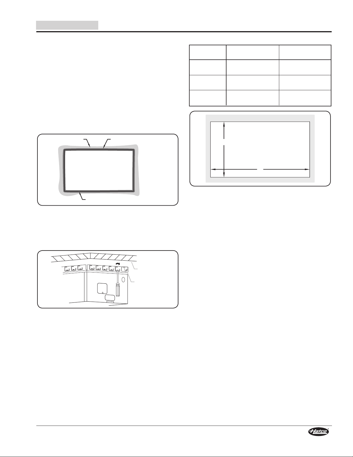
3. Place ribbon putty gasket around the cutout edge of the
countertop. Make sure the ribbon putty gasket overhangs
the cutout edge or seal unit with silicone adhesive.
NOTE: A roll of ribbon putty gasket material is supplied with the
unit.
Installing Ribbon Putty Gasket
4. Place the unit into the countertop opening.
5. Using a screwdriver, rotate the unit’s EZ locking tabs
outward to secure the unit to the underside of the
countertop. Rotate as many tabs as needed to secure the
unit to the countertop.
Countertop Cutout Dimensions
Model Width (A) Depth (B)
DHWBI-S2
DHWBI-S3
DHWBI-S4
NOTE: Required minimum clearance below countertop cutout
is 17-3/16″ (437 mm).
44″ – 44-1/8″
(1116 – 1122 mm)
66″ – 66-1/8″
(1675 – 1680 mm)
88″ – 88-1/8″
(2234 – 2239 mm)
Countertop Cutout Dimensions
14-1/16″ – 14-1/4″
(357 – 362 mm)
14-1/16″ – 14-1/4″
(357 – 362 mm)
14-1/16″ – 14-1/4″
(357 – 362 mm)
NOTE: The Hatco EZ locking tabs work on countertops
6. Carefully trim and remove the excess ribbon putty material
7. Install the control enclosure(s). Refer to the “Installing a
Form No. DHWBISM-0519
EZ Locking Tabs
that have a maximum thickness of 3/16″ (5 mm).
For countertops 3/16″–2″ (5–51 mm) thick, use an
appropriate number of accessory thick counter adapter
brackets (HWB-MNT-REC ). Refer to the OPTIONS
AND ACCESSORIES section for Adapter Bracket
installation information.
from around the unit.
Remote Control Enclosure” procedure in this section.
7
Page 8
WARNING
Typical knockout
locations for power
source connection.
Control
Enclosure
INSTALLATION
A
C
D
B
Left Side View –
Control Enclosure
Silicone Sealant
7/16″
(11 mm)
3/8″
(9 mm)
6-1/2″
(165 mm)
1-1/2″
(38 mm)
English
Installing a Remote Control Enclosure
Remote control enclosures must be mounted on the front of
the unit to ensure the controls correspond with the correct wells
(the front of the unit is the side the conduit enters under the
unit). Remote control enclosures cannot be rewired and must
be installed in the proper location.
NOTE: A qualified electrician should connect the unit(s) to a
power source.
ELECTRIC SHOCK HAZARD: Remote control enclosure
must be mounted on vertical wall and installed in vertical
position. Mounting remote control enclosure in horizontal
position may result in collection of liquids and lead to
electric shock.
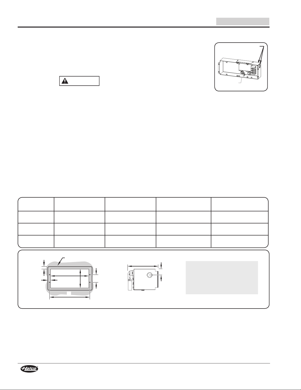
1. Cut and drill the appropriate holes in the mounting surface.
Refer to the “Control Enclosure Cutout Dimensions” chart
below for the cutout dimensions for each control enclosure.
• The cutout depth required for all control enclosures is
6-1/2″ (165 mm).
• Make sure to have enough space inside the cutout if
installing with conduit on the side of the control enclosure.
• For units with two control enclosures: Each enclosure
cutout size may be different (see chart below).
2. Remove the trim cover from the control enclosure.
3. Position the control enclosure into the opening through the
backside.
4. Secure the control enclosure to the mounting surface
using screws (#8 sheet metal screw supplied).
5. Connect the proper power
source to the mounted
remote control enclosure.
Wiring must be fixed a
minimum of 4″ (102 mm)
from bottom of well(s).
6. Apply a 1/4″ (6 mm) bead
of NSF-approved silicone
sealant where the trim cover
will contact the cabinet surface. Refer to the “Control
Enclosure Cutout and Screw Hole Dimensions” illustration
for more information.
7. Reinstall the trim cover on the control enclosure and
secure in position using the four trim cover screws. Make
sure to embed the trim cover edge into the silicone.
NOTE: Standard UL approved units are equipped with a
72″ (1829 mm) flexible conduit connected to the remote
control enclosure.
Control Enclosure Cutout Dimensions
Model
DHWBI-S2
DHWBI-S3
DHWBI-S4
Opening Dimension
Width (A)
10-5/16″
(262 mm)
14-5/16″
(364 mm)
18-5/16″
(465 mm)
Opening Dimension
Height (B)
Control Enclosure Cutout and Screw Hole Dimensions
4-3/4″
(119 mm)
4-3/4″
(119 mm)
4-3/4″
(119 mm)
Screw Hole Dimension
Width (C)
10-9/16″
(269 mm)
14-9/16″
(370 mm)
18-9/16″
(472 mm)
IMPORTANT NOTE:
Make sure the installation location
provides enough room for electrical
connections to the control enclosure.
Follow local and national plumbing
and electrical codes.
Screw Hole Dimension
Height (D)
2-1/2″
(64 mm)
2-1/2″
(64 mm)
2-1/2″
(64 mm)
8
Form No. DHWBISM-0519
Page 9
English
WARNING
CAUTION
WARNING
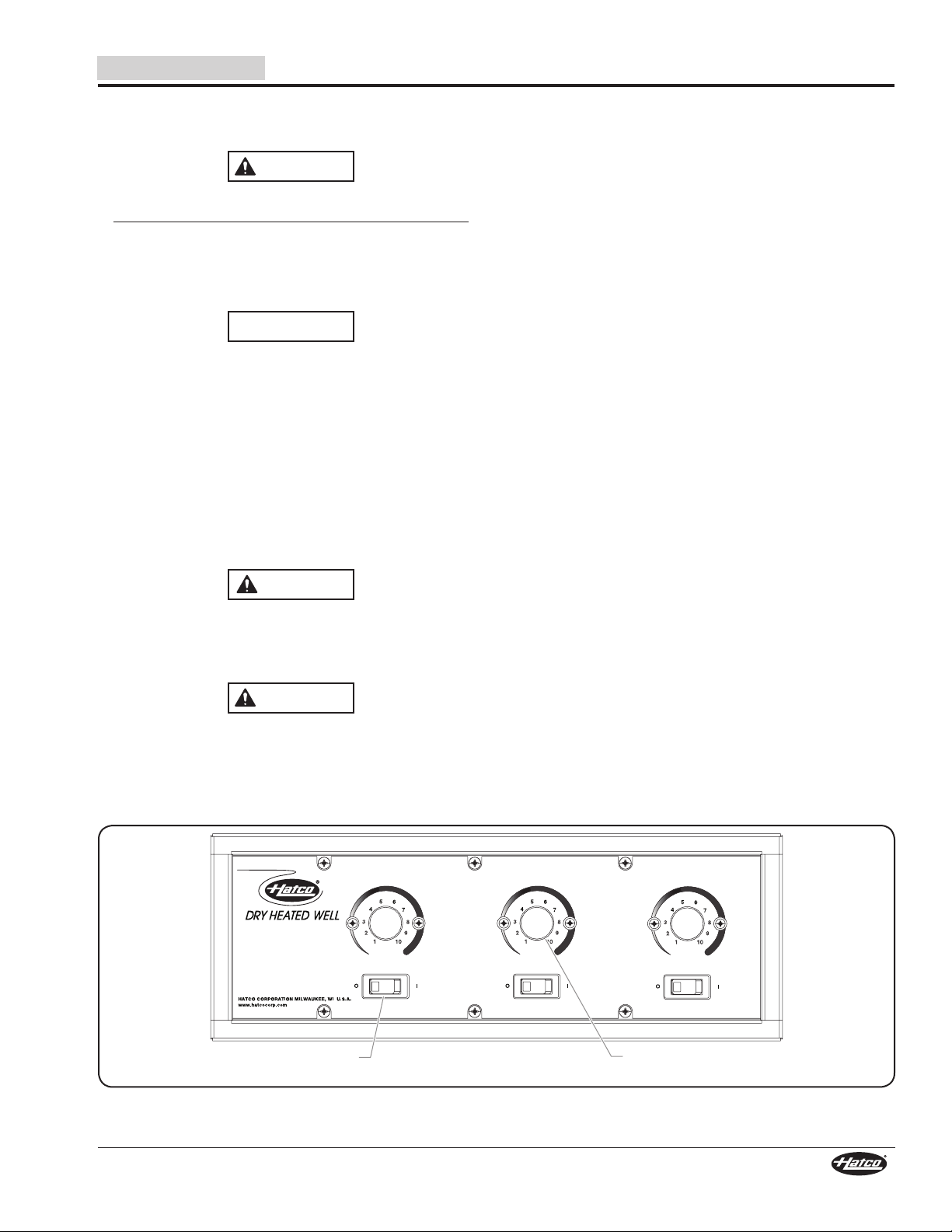
Temperature Control
Knob
Power I/O (on/off)
Switch
OPERATION
General
Use the following procedures to operate the Built-In Modular
Slim Dry Heated Wells.
Read all safety messages in the Important Safety
Information section before operating this equipment.
ELECTRIC SHOCK HAZARD: Do not use unit to melt or
hold ice. Doing so may cause condensation, creating
an electrical hazard and causing personal injury and/or
damage to unit. Damage caused by condensation is not
covered by warranty.
NOTICE
Standard and approved manufacturing oils may smoke up
to 30 minutes during initial startup. This is a temporary
condition. Operate unit without food product until smoke
dissipates.
Startup
1. Prepare the wells for operation.
2. Place an empty pan in each well or cover each well with
a lid. This step is recommended to speed up pre-heating
and reach operating temperature.
3. Move the Power I/O (on/off) switch(es) to the I (on)
position. The indicator light on each switch glows when it
is on.
Food Warming
Place the appropriate size food pans with pre-heated food
product into the Slim Dry Heated Wells.
• Always use a food pan. Do not place food directly into the
heated well.
• Stir thick food items frequently to keep food heated
uniformly.
• Keep pans covered to maintain food quality and
temperature.
Shutdown
1. Move the Power I/O (on/off) switches to the O (off) position.
The indicator light on the switches will shut off.
NOTE: If a catch pan is used underneath the drain fitting, make
sure the catch pan is emptied after each spill to prevent
overflowing.
BURN HAZARD: Some exterior surfaces on the unit will
get hot. Use caution when touching these areas.
4. Turn the Temperature Control Knob(s) to the desired
setting.
Hatco Corporation is not responsible for actual food
product serving temperature. It is the responsibility of the
user to ensure that food product is held and served at a
safe temperature.
5. Allow the unit to preheat for approximately 30 minutes.
Form No. DHWBISM-0519
Control Enclosure
9
Page 10

MAINTENANCE
CAUTION
Fan Blade
Wing Nut
Reverse
Threaded Stud
Lower
Fan Cover
Upper Fan
Cover
Screws
Slots
Washer
English
General
The Hatco Built-In Modular Slim Dry Heated Wells are designed
for maximum durability and performance, with minimum
maintenance.
WARNING
ELECTRIC SHOCK HAZARD:
• Turn power switch OFF, disconnect unit from power
source, and allow unit to cool before performing any
maintenance or cleaning.
• DO NOT submerge or saturate with water. Unit is not
waterproof. Do not operate if unit has been submerged
or saturated with water.
• Do not clean unit when it is energized or hot.
• This unit is not “jet-proof” construction. Do not use
jet-clean spray to clean this unit.
FIRE HAZARD: Do not use flammable cleaning solutions
to clean this unit.
This unit has no “user-serviceable” parts. If service
is required on this unit, contact an Authorized Hatco
Service Agent or contact the Hatco Service Department at
800-558-0607 or 414-671-6350.
Do not use steel wool or metal scouring pad for cleaning.
Steel wool will scratch the finish.
Use non-abrasive cleaners and cloths only. Abrasive
cleaners and cloths could scratch finish of unit, marring its
appearance and making it susceptible to soil accumulation.
Do not use harsh chemicals such as bleach, cleaners
containing bleach, or oven cleaners to clean this unit.
Damage caused by chemicals is not covered by warranty.
Monthly Cleaning
To preserve the finish of the heated well(s), perform the
following cleaning procedure monthly to remove any debris in
the well caused by spills.
1. Move the Power I/O (on/off) switches to the O (off) position
and allow the unit to cool completely.
2. Remove and wash any pans and adapters.
3. Remove the fan covers by removing the two Phillips head
screws and lifting the two covers out of the well.
4. Remove and wash the fan blade by holding the fan blade
and unscrewing the wing nut clockwise and removing the
washer (the wing nut is reverse-threaded).
5. Wipe down the entire unit using a clean cloth or sponge
and mild detergent.
6. Use a plastic scouring pad to remove any hardened food
particles.
7. Wipe dry the entire unit using a non-abrasive, dry cloth.
8. Reinstall the fan blade and the fan covers using the washer
and wing nut.
Daily Cleaning
To preserve the finish of the heated well(s), perform the
following cleaning procedure daily.
1. Move the Power I/O (on/off) switches to the O (off) position
and allow the unit to cool.
2. Remove and wash any pans and adapters.
3. Wipe down the entire unit using a clean cloth or sponge
and mild detergent.
4. Use a plastic scouring pad to remove any hardened food
particles.
5. Wipe dry the entire unit using a non-abrasive, dry cloth.
NOTE: If a catch pan is used underneath the drain fitting,
make sure the pan is emptied regularly to prevent overflowing.
Monthly Cleaning (Inside View of Well)
10
Form No. DHWBISM-0519
Page 11

English
WARNING
WARNING
TROUBLESHOOTING GUIDE
This unit must be serviced by qualified personnel only.
Service by unqualified personnel may lead to electric
shock or burn.
ELECTRIC SHOCK HAZARD: Turn OFF power switch,
unplug power cord, and allow unit to cool before
performing any cleaning, adjustments, or maintenance.
Symptom Probable Cause Corrective Action
Unit not hot enough. Temperature Control set too low. Adjust Temperature Control to a higher setting.
Heating element not working.
Temperature Control not working properly.
Voltage supplied is incorrect. Verify correct voltage is supplied to unit. Low supply voltage will
Unit too hot. Temperature Control set too high. Adjust Temperature Control to a lower setting.
Temperature Control not working properly. Contact Authorized Service Agent or Hatco for assistance.
Voltage supplied is incorrect. Verify correct voltage is supplied to unit. High supply voltage will
No heat. Unit turned off. Move the Power I/O (on/off) switches to the I (on) position
Circuit breaker tripped. Reset circuit breaker. If circuit breaker continues to trip, contact
Temperature Control not working properly.
Power I/O (on/off) switch not working.
Temperature control knobs
heat wrong well.
Control enclosure installed incorrectly. Install control enclosure on the front side of the unit. Contact
Contact Authorized Service Agent or Hatco for assistance.
cause improper heating.
cause unit to overheat and may damage the unit.
Authorized Service Agent or Hatco.
Contact Authorized Service Agent or Hatco for assistance.Heating element not working.
Authorized Service Agent or Hatco for assistance.
Troubleshooting Questions?
If you continue to have problems resolving an issue, please contact the nearest Authorized Hatco Service Agency or Hatco for
assistance. To locate the nearest Service Agency, log onto the Hatco website at www.hatcocorp.com, select the Support pulldown menu, and click on “Find A Service Agent”; or contact the Hatco Parts and Service Team at:
Telephone: 800-558-0607 or 414-671-6350
e-mail: support@hatcocorp.com
Form No. DHWBISM-0519
11
Page 12

OPTIONS AND ACCESSORIES
12″ (305 mm)
Pan Support Bars
20″ (508 mm)
Pan Support Bar
7 Quart (7 Liter)
Adapter Top
4 Quart (4 Liter)
Adapter Top
1/2 Trivet
Full Trivet
1/4 Trivet
English
Pan Support Bars
The following pan support bars are available to divide the Dry
Heated Wells into sections for different size pans.
HWBGM12BAR ... 12″ (305 mm) Pan Support Bar
HWBGM20BAR ... 20″ (508 mm) Pan Support Bar
Pan Support Bars
Adapter Tops
The following adapter tops are available to allow rectangular
Dry Heated Wells to hold round pans.
HWB-2-7Q .......... Adapter to convert DHWBI Series heated
wells to hold two 7 quart (7 liter) round pans.
HWB-3-4Q .......... Adapter to convert DHWBI Series heated
wells to hold three 4 quart (4 liter) round pans.
Trivets
Stainless steel or nickel-plated trivets are available in various
sizes.
TRIVET (1/4)SS..... Quarter-size stainless steel trivet —
8-1/2″W 4-1/2″D (216 mm x 114 mm)
TRIVET (1/2)SS..... Half-size stainless steel trivet —
10-3/16″W x 7-5/8″D (259 mm x 194 mm)
TRIVET SS ............ Full size stainless steel trivet —
10-1/8″W x 18″D (257 mm x 457 mm)
TRIVET (1/2) ......... Half-size nickel-plated trivet —
10-3/16″W x 7-5/8″D (259 mm x 194 mm)
TRIVET .................. Full size nickel-plated trivet —
10-1/8″W x 18″D (257 mm x 457 mm)
Adapter Tops
Trivets
Over-Sized Bezel
An over-sized bezel is available for all models as a nonretrofittable option. Models with an over-sized bezel match the
depth dimensions of a Hatco Refrigerated Drop-In Well.
12
Form No. DHWBISM-0519
Page 13

English
4 Quart (4 l)
Round Pan
4 Quart (4 l)
Notched Lid
7 Quart (7 l)
Notched Lid
4 Quart (4 l)
Hinged Lid
7 Quart (7 l)
Hinged Lid
7 Quart (7 l)
Round Pan
1/2 Pan,
2-1/2″ (64 mm) Deep
1/3 Pan,
2-1/2″ (64 mm) Deep
Full Pan,
2-1/2″ (64 mm) Deep
Full Pan,
4″ (102 mm) Deep
Insert bracket
into slot in
EZ locking tab.
Bolt
(included
with bracket)
Adapter
Bracket
Tighten bolt against
underside of
countertop.
OPTIONS AND ACCESSORIES
Food Pans
Stainless steel food pans are available in various sizes.
ST PAN 1/3 ........ Third-size stainless steel pan —
12-3/4″W x 6-7/8″D x 2-1/2″H (324 x
175 x 64 mm)
ST PAN 1/2 ........ Half-size stainless steel pan —
12-3/4″W x 10-3/8″D x 2-1/2″H (324 x
264 x 64 mm)
ST PAN 2 ........... Full size stainless steel pan at 2-1/2″ (64 mm)
deep — 12-3/4″W x 20-3/4″D x 2-1/2″H (324 x
527 x 64 mm)
ST PAN 4 ........... Full size stainless steel pan at 4″ (102 mm)
deep — 12-3/4″W x 20-3/4″D x 4″H (324 x 527
x 102 mm)
4QT-PAN ............ 4 quart (4 liter) round pan — 6-3/4″ dia. x 8″
(171 mm dia. x 203 mm)
7QT-PAN ............ 7 quart (7 liter) round pan — 8-11/16″ dia. x 8″
(221 mm dia. x 203 mm)
4QT-LID-1 ..........4 quart (4 liter) round, notched lid
7QT-LID-1 ..........7 quart (7 liter) round, notched lid
4QT-LID ..............4 quart (4 liter) round, hinged and notched lid
7QT-LID ..............7 quart (7 liter) round, hinged and notched lid
Attached Cord and Plug
An attached cord and plug is available as a factory-installed
option for models with a single phase electrical configuration.
Use the following procedure to install the control.
1. Refer to the “Installing a Remote Control Enclosure”
procedure in the INSTALLATION section.
2. Plug unit into a properly grounded electrical receptacle
of the correct voltage, size, and plug configuration. See
SPECIFICATIONS section for details.
Adapter Bracket
HWB-MNT-REC
Adapter brackets (8) for installing Dry Heated Wells into non-
combustible countertops that are 3/16″–2″ (5–52 mm) thick.
Stainless Steel Food Pans
Thick Countertop Adapter Bracket
Form No. DHWBISM-0519
13
Page 14

LIMITED WARRANTY
English
1. PRODUCT WARRANTY
Hatco warrants the products that it manufactures (the “Products”)
to be free from defects in materials and workmanship, under
normal use and service, for a period of one (1) year from the
date of purchase when installed and maintained in accordance
with Hatco’s written instructions or 18 months from the date
of shipment from Hatco. Buyer must establish the Product’s
purchase date by registering the Product with Hatco or by other
means satisfactory to Hatco in its sole discretion.
Hatco warrants the following Product components to be free
from defects in materials and workmanship from the date of
purchase (subject to the foregoing conditions) for the period(s)
of time and on the conditions listed below:
a) One (1) Year Parts and Labor PLUS One (1) Additional
Year Parts-Only Warranty:
Conveyor Toaster Elements (metal sheathed)
Drawer Warmer Elements (metal sheathed)
Drawer Warmer Drawer Rollers and Slides
Strip Heater Elements (metal sheathed)
Display Warmer Elements (metal sheathed air heating)
Holding Cabinet Elements (metal sheathed air heating)
Heated Well Elements — HW and HWB Series
(metal sheathed)
b) Two (2) Year Parts and Labor Warranty:
Induction Ranges
Induction Warmers
c) One (1) Year Parts and Labor PLUS Four (4) Years
Parts-Only Warranty:
3CS and FR Tanks
d) One (1) Year Parts and Labor PLUS Nine (9) Years
Parts-Only Warranty on:
Electric Booster Heater Tanks
Gas Booster Heater Tanks
e) Ninety (90) Day Parts-Only Warranty:
Replacement Parts
THE FOREGOING WARRANTIES ARE EXCLUSIVE AND
IN LIEU OF ANY OTHER WARRANTY, EXPRESSED OR
IMPLIED, INCLUDING BUT NOT LIMITED TO ANY IMPLIED
WARRANTY OF MERCHANTABILITY OR FITNESS FOR
A PARTICULAR PURPOSE OR PATENT OR OTHER
INTELLECTUAL PROPERTY RIGHT INFRINGEMENT. Without
limiting the generality of the foregoing, SUCH WARRANTIES
DO NOT COVER: Coated incandescent light bulbs, fluorescent
lights, heat lamp bulbs, coated halogen light bulbs, halogen
heat lamp bulbs, xenon light bulbs, LED light tubes, glass
components, and fuses; Product failure in booster tank, fin
tube heat exchanger, or other water heating equipment caused
by liming, sediment buildup, chemical attack, or freezing;
or Product misuse, tampering or misapplication, improper
installation, or application of improper voltage.
2. LIMITATION OF REMEDIES AND DAMAGES
Hatco’s liability and Buyer’s exclusive remedy hereunder will
be limited solely, at Hatco’s option, to repair or replacement
using new or refurbished parts or Product by Hatco or a Hatcoauthorized service agency (other than where Buyer is located
outside of the United States, Canada, United Kingdom, or
Australia, in which case Hatco’s liability and Buyer’s exclusive
remedy hereunder will be limited solely to replacement of part
under warranty) with respect to any claim made within the
applicable warranty period referred to above. Hatco reserves
the right to accept or reject any such claim in whole or in part. In
the context of this Limited Warranty, “refurbished” means a part
or Product that has been returned to its original specifications
by Hatco or a Hatco-authorized service agency. Hatco will not
accept the return of any Product without prior written approval
from Hatco, and all such approved returns shall be made
at Buyer’s sole expense. HATCO WILL NOT BE LIABLE,
UNDER ANY CIRCUMSTANCES, FOR CONSEQUENTIAL
OR INCIDENTAL DAMAGES, INCLUDING BUT NOT LIMITED
TO LABOR COSTS OR LOST PROFITS RESULTING FROM
THE USE OF OR INABILITY TO USE THE PRODUCTS OR
FROM THE PRODUCTS BEING INCORPORATED IN OR
BECOMING A COMPONENT OF ANY OTHER PRODUCT OR
GOODS.
14
Form No. DHWBISM-0519
Page 15

Français
AVERTISSEMENT
ATTENTION
SOMMAIRE
Informations Importantes pour le Propriétaire ....................15
Introduction .........................................................................15
Consignes de Sécurité Importantes ................................. 16
Description du Modèle ....................................................... 17
Désignation du Modèle ...................................................... 18
Caractéristiques Techniques ............................................18
Configuration des Fiches ................................................... 18
Tableau des Caractéristiques électriques.......................... 18
Dimensions ........................................................................ 18
Installation ...........................................................................19
Généralités ........................................................................19
Installer l'appareil ............................................................... 20
Dimensions de découpe du comptoir ................................ 20
Installation d'un boîtier de commande à distance ............. 21
Dimensions de la découpe du boîtier de commande ........ 21
INFORMATIONS IMPORTANTES POUR LE PROPRIÉTAIRE
Notez le numéro de modèle, le numéro de série, la tension
et la date d’achat de l’appareil dans les espaces ci-dessous
(Étiquette des caractéristiques techniques située au dos de
l'appareil). Veuillez avoir cette information à portée de la main
si vous appelez Hatco pour assistance.
Modèle No. ______________________________________
Numéro de série __________________________________
Voltage _________________________________________
Date d’achat _____________________________________
Enregistrez votre appareil!
Remplissez la garantie en ligne pour éviter les retards
pour faire jouer la garantie. Accédez au site Web Hatco
www.hatcocorp.com, sélectionnez le menu déroulant
Support (Assistance), puis cliquez sur « Warranty » (Garantie).
Mode d’emploi ....................................................................22
Généralités ........................................................................22
Maintenance ........................................................................ 23
Généralités ........................................................................23
Nettoyage quotidien ...........................................................23
Nettoyage mensuel ............................................................23
Guide de Dépannage ..........................................................24
Options et accessoires ...................................................... 25
Garantie Limitée .................................................................27
Autorisés Distributeurs de Pièces ........Couverture Arrière
Horaires
ouvrables : 7h00 à 17h00 Heure du Centre (CT)
(Horaires d’été : juin à septembre—
7h00 à 17h00 du lundi au jeudi
7h00 à 16h00 le vendredi)
Téléphone: 800-558-0607; 414-671-6350
Courriel: support@hatcocorp.com
Service d'assistance et de pièces de
rechange disponible 7j/7, 24h/24 aux
États-Unis et au Canada en composant
le 800-558-0607.
Des renseignements supplémentaires sont disponibles sur
notre site Web à www.hatcocorp.com.
Les puits chauffants secs intégrés modulaires allongés d’Hatco
sont spécialement conçus pour conserver des aliments chauds
à des températures sans danger pour le service. Les puits secs
sont disponibles dans toute une gamme de combinaisons de
bacs ; tous chauffés grâce à un élément chauffant de longue
durée garanti deux ans. L'élément de chauffage en métal est
contrôlé à distance par un thermostat. La chaleur est distribuée
de manière égale à travers un élément en acier inoxydable
épais pour s'assurer que la nourriture reste chaude. Ce modèle
est facile d'entretien et offre des performances durables. Tous
les appareils sont classés UL et sont équipés d'un boîtier de
commandes à distance.
Les appareils sont équipés du matériel de fixation EZ lock.
Les commandes incluent des interrupteurs d'alimentation
individuels éclairés et des commandes de thermostat pour
gérer les paramètres de température. La garantie d'un an
pour les pièces ainsi que pour la main d'œuvre sur place est
standard.
Les puits chauffants secs intégrés modulaires d'Hatco sont des
produits qui ont bénéficié de recherche extensive et d'essais
sur le terrain. Les matériaux utilisés ont été sélectionnés
pour un maximum de durabilité, d’aspect esthétique et de
performance optimum. Chaque appareil est minutieusement
inspecté et testé avant expédition.
Formulaire n° DHWBISM-0519
INTRODUCTION
Ce manuel fournit les instructions d’installation, de sécurité
et de fonctionnement pour les puits chauffants secs intégrés
modulaires allongés. Hatco vous recommande de lire
l’ensemble des instructions d’installation, de sécurité et de
fonctionnement contenues dans ce manuel avant d’installer et
d’utiliser l’appareil.
Les consignes de sécurité qui apparaissent dans ce manuel
sont identifiées par les mots indicateurs suivants :
AVERTISSEMENT indique une situation dangereuse qui,
si elle n’est pas évitée, peut provoquer la mort ou des
blessures graves.
ATTENTION indique une situation dangereuse qui, si elle
n’est pas évitée, peut provoquer des blessures légères ou
moyennes.
AVIS
AVIS est utilisé pour des questions sans rapport avec des
blessures corporelles.
15
Page 16

CONSIGNES DE SÉCURITÉ IMPORTANTES
AVERTISSEMENT
ATTENTION
AVERTISSEMENT
Lisez l’information de securite importante suivante avant d’utiliser cet équipement pour éviter
des dommages ou la mort sérieux et pour éviter d’endommager l’équipement ou la propriété.
Français
DANGER DE DÉCHARGE ÉLECTRIQUE :
• Mettez l'interrupteur hors tension, débranchez
l'appareil de la source d'alimentation et laissez-le
refroidir avant d'effectuer toute tâche d'entretien ou de
nettoyage.
• NE PAS immerger l’appareil ni le saturer d’eau.
L’appareil n’est pas étanche à l’eau. Ne pas le faire
fonctionner s’il a été immergé ou saturé d’eau.
• L’appareil n'est pas étanche. Placez l'appareil à
l'intérieur d'un local dont la température ambiante se
situe entre 21°C (70°F) et 29°C (85°F).
• Le boîtier de commandes à distance doit être installé
en position verticale sur un mur vertical. L'installation
sur une surface horizontale entraîne un risque
d'accumulation de liquide et d'électrocution.
• N'utilisez pas l'unité pour faire fondre ou conserver
de la glace. Le non-respect de cette consigne peut
causer de la condensation, créer un danger électrique
et causer des blessures corporelles et/ou endommager
l'unité. Les dommages causés par la condensation ne
sont pas couverts par la garantie.
• Ne pas nettoyer l'appareil tant qu'il est branché ou
chaud.
• Cet appareil n’est pas étanche aux jets. Ne pas utiliser
de jet sous pression pour nettoyer l’appareil.
• La réparation de cet appareil doit être confiée
exclusivement à du personnel qualifié. Les réparations
par des personnes non qualifiées peuvent provoquer
des décharges électriques et des brûlures.
• Pour les réparations, utiliser exclusivement des pièces
de rechange Hatco d’origine. Utilisez des pièces
détachées Hatco authentiques sous peine d’annuler
toutes les garanties et d’exposer l’utilisateur à des
tensions électriques dangereuses pouvant entraîner
une électrocution ou des brûlures. Les pièces
de rechange Hatco d’origine sont conçues pour
fonctionner sans danger dans les environnements
dans lesquels elles sont utilisées. Certaines pièces
de rechange génériques ou de second marché ne
présentent pas les caractéristiques leur permettant de
fonctionner sans danger dans la matériel Hatco.
DANGER D’INCENDIE :
• Installez l’appareil avec un minimum de 114 mm
(4-1/2″)d’espace entre le bas del’appareilet toutes
les surfaces. Si ces distances de sécurité ne sont pas
respectées, une combustion peut se produire.
• L'unité doit être installée en utilisant un joint mastic
en bandes entre l'unité et la surface d'installation,
conformément aux instructions d'installation (reportezvous à la section Installation de ce manuel).
• N'utilisez pas de nettoyant inflammable pour nettoyer
cet appareil.
L'élément doit être installé par des installateurs formés
et qualifiés. L'installation doit être conforme à l'ensemble
des réglementations électriques locales. Vérifiez les
procédures et les normes à suivre auprès de vos
inspecteurs locaux en matière d'électricité.
Cet appareil ne doit pas être utilisé par des enfants ou des
personnes avec des capacités physiques, sensorielles ou
mentales diminuées. Assurez-vous que les enfants sont
bien surveillés et tenez-les à l’écart de l’appareil.
Assurez-vous que tous les opérateurs ont été formés à
l’utilisation sûre et correcte de l’appareil.
S’assurer que le produit alimentaire a été chauffé à une
température adaptée au maintien de sa salubrité avant de
le mettre sur l’appareil sous peine de risques graves pour
la santé. Cet appareil est destiné au maintien de produits
alimentaires préchauffés uniquement.
Hatco n’est pas responsable de la température de service
du produit alimentaire elle-même. Il incombe à l’utilisateur
de s’assurer que le produit alimentaire est maintenu et
servi à une température sûre.
Cet appareil ne contient aucune pièce réparable par
l’utilisateur. Si cet appareil doit être réparé, contacter un
réparateur Hatco agréé ou le Service après-vente Hatco au
800-558-0607 ou 414-671-6350.
DANGER DE BRÛLURE :
• Certaines surfaces extérieures de l’appareil deviennent
chaudes. Toucher ces zones de l’appareil avec
précaution.
• NE nettoyez PAS l'unité tant qu'elle contient des
aliments. Retirez les aliments et laissez l'unité refroidir
complètement avant de la nettoyer.
Placez l’appareil sur un plan de travail dont la hauteur
est appropriée, à un emplacement pratique à utiliser.
L'emplacement doit être assez solide pour supporter le
poids de l'appareil et son contenu.
AVIS
Les appareils ne fonctionnent qu'à la tension spécifiée.
Reportez-vous à l'étiquette des caractéristiques des
exigences électriques avant de commencer l'installation.
Les graisses standard et approuvées utilisées lors de la
fabrication peuvent provoquer des fumées au cours du
démarrage initial pendant 30 minutes. Il s'agit d'un état
temporaire. Utilisez l'appareil sans produit alimentaire
jusqu'à ce que la fumée disparaisse.
Ne placez pas l'appareil dans une zone soumise à des
températures excessives ou exposée à de la graisse
provenant de grils, poêles, etc. Des températures
excessives risquent d'endommager l'appareil.
L'unité est conçue et recommandée pour fonctionner
encastrée ou posée sur un comptoir en métal. La garantie
Hatco ne couvre pas les dommages faits à la table de
travail. Pour les autres surfaces, vérifiez auprès de leurs
fabricants que le matériau peut supporter de façon durable
des températures atteignant 93°C (200°F).
N'utilisez pas de laine d'acier ou de tampon de décapage en
métal pour le nettoyage. La paille de fer raye les finitions.
16
Formulaire n° DHWBISM-0519
Page 17

Français
DHWBI-S4
DHWBI-S3
DHWBI-S2
CONSIGNES DE SÉCURITÉ IMPORTANTES
AVIS
Utilisez uniquement des nettoyants non abrasifs et des
chiffons doux. Les chiffons et nettoyant abrasifs pourraient
rayer la finition de l’unité, altérant son apparence et la
rendant vulnérable à l’accumulation de saleté.
L'utilisation de produits chimiques agressifs tels que l'eau
de javel, les produits nettoyants contenant de la javel, ou
les produits de nettoyage pour les fours sont proscrits
pour nettoyer l'appareil. Les dommages causés par des
produits chimiques ne sont pas couverts par la garantie.
Tous les modèles
Tous les puits chauffants secs modulaires allongés intégrés sont
fiables et polyvalents. Chaque unité dispose d'un compartiment
en acier inoxydable et aluminium accompagné d'un élément de
chauffage en métal. L'élément de chauffage est contrôlé par un
système de commande de la température thermostatique et un
interrupteur Marche/Arrêt situés dans le boîtier de commande
à distance. Le système de chauffage/circulation d'air fournit
une température constante dans chaque puits. Le boîtier de
commande à distance est relié à l'unité via un ensemble de
conduit flexible de 1 829 cm (6′). Les puits chauffants secs
intégrés modulaires peuvent avoir un cordon d'alimentation ou
être branchés directement sur une source d'alimentation pour
une zone de service sûre et sans fil.
Tous les modèles sont équipés de matériel de fixation EZ lock
et conçus pour être installés sur la partie supérieure d'une table
de travail non-combustible. Les puits chauffants secs intégrés
modulaires sont conçus, fabriqués et testés pour conserver les
aliments à une température sans danger.
AVIS
N'installez pas l’appareil dans un endroit présentant des
déplacements d'air excessifs. Évitez les zones pouvant
être soumises à des déplacements d’air ou à des courants
d’air actifs (proximité de ventilateurs d’extraction/de hottes
d’aspiration, de conduites de climatisation et de portes
extérieures).
DESCRIPTION DU MODÈLE
Modèles DHWBI-S2, -S3, et -S4
Les modèles DHWBI peuvent contenir toute une gamme de
combinaisons de bacs dans chaque puits chauffant.
• Un bac de grande taille
• Deux bacs de taille moyenne avec des barres d'adaptation.
• Trois bacs de petite taille avec des barres d'adaptation.
• Six bacs de très petite taille avec des barres d'adaptation.
• Deux bacs ronds 6,6 litres avec un adaptateur.
• Trois bacs ronds 3,8 litres avec un adaptateur.
Les bacs alimentaires, les barres de support de bacs et les
ustensiles adaptables sont vendus séparément (reportez-vous
à la rubrique OPTIONS ET ACCESSOIRES de ce manuel).
REMARQUE IMPORTANTE
Installez le boîtier de commande sur la partie
avant de l'appareil pour vous assurer que les
commandes correspondent bien aux puits
concernés (la partie avant de l'appareil est le côté
par lequel le conduit entre sous l'appareil). Les
boîtiers de commande à distance ne peuvent pas
être recâblés et doivent être installés dans un
endroit approprié.
Formulaire n° DHWBISM-0519
NOTA: Les commandes séparées sont également disponibles. Tous
les modèles pour le Canada requièrent des commandes avec
un seul boîtier de commandes.
17
Page 18

DÉSIGNATION DU MODÈLE
AVERTISSEMENT
NEMA 5-15P NEMA 5-20P
NEMA 5-30P
NEMA L14-20P
Puits chauffant sec
Contenance du bac grande taille
Montage en haut, isolé
Built-In (encastré)
D H W B I - S x
Allongé
CARACTÉRISTIQUES TECHNIQUES
Configuration des fiches
Certaines unités sont fournies par l'usine avec un câble et
une fiche électriques préinstallés. Les fiches sont fournies
conformément à l'application (non disponibles avec les
commandes séparées). Pour plus de détails, consultez la
section OPTIONS ET ACCESSOIRES.
DANGER DE DÉCHARGE ÉLECTRIQUE : Brancher
l’appareil sur une prise de courant avec terre de tension,
de format et de configuration des broches corrects. Si la
fiche et la prise ne se correspondent pas, s’adresser à un
électricien qualifié pour déterminer et installer une prise
de courant de format et de tension corrects.
NOTA: Étiquette de caractéristiques techniques située sur le
côté de l'unité. Consultez l'étiquette pour connaître
le numéro de série et vérifier les caractéristiques
électriques de l’appareil.
Français
Configuration des fiches
NOTA: Prise non fournie par Hatco.
Tableau des Caractéristiques électriques
Configuration de Fiches
Modéle Tension Hertz Intensité Amps
DHWBI-S2 120
120/208–240 8.0 NEMA L14-20P
DHWBI-S3 120
120/208–240 16.0 NEMA L14-20P
DHWBI-S4 120/208–240 60 3840 16.0 NEMA L14-20P 78 kg (172 lbs.)
NOTA: Les poids d’expédition sont estimés.
60 1920
60 2880
16.0 NEMA 5-20P
24.0 NEMA 5-30P
(en option)
d’embarquement
42 kg (93 lbs.)
60 kg (133 lbs.)
Dimensions
Largeur
Modéle
DHWBI-S2
DHWBI-S3
DHWBI-S4
* Les appareils avec un cadre grande dimension ont une profondeur (B) de 686 mm (27″).
(A)
1156 mm
(45-1/2″)
1715 mm
(67-1/2″)
2273 mm
(89-1/2″)
Profondeur
(B) *
397 mm
(15-5/8″)
397 mm
(15-5/8″)
397 mm
(15-5/8″)
Hauteur
(C)
321 mm
(12-11/16″)
321 mm
(12-11/16″)
321 mm
(12-11/16″)
18
Formulaire n° DHWBISM-0519
Poids
Page 19

Français
ATTENTION
Vue de côté
Vue de face
A
Bride de
8 mm
(5/16″)
B
C
CARACTÉRISTIQUES TECHNIQUES
INSTALLATION
Général
Les puits chauffants secs intégrés modulaires allongés sont
fournis par l’usine avec la plupart des composants assemblés
et prêts à l’emploi. Utilisez les procédures suivantes pour
l'installation de l'appareil.
NOTA: Pour tous les puits chauffants secs intégrés modulaires,
le boîtier de commandes doit être installé pour pouvoir
fonctionner à distance.
NOTA: Assurez-vous que l'emplacement pour l'installation
fournit suffisamment de place pour le boîtier de
commandes à distance intégré et les connexions
électriques.
AVERTISSEMENT
RISQUE DE DÉCHARGE ÉLECTRIQUE : L’appareil n'est
pas étanche. Placez l'appareil à l'intérieur d'un local dont
la température ambiante se situe entre 21°C (70°F) et 29°C
(85°F).
RISQUE D'INCENDIE :
• Installez l’appareil avec un minimum de 114 mm
(4-1/2″) d’espace entre lebas de l’appareil et toutes
les surfaces. Si ces distances de sécurité ne sont pas
respectées, une combustion peut se produire.
• L'appareil doit être installé à l'aide d'un joint mastic en
bandes placé entre l'appareil et la surface d'installation
conformément aux instructions d'installation.
L'élément doit être installé par des installateurs formés
et qualifiés. L'installation doit être conforme à toutes les
normes locales en matière d'électricité et de plomberie.
Vérifiez les procédures et les normes à suivre auprès
de vos inspecteurs locaux en matière de plomberie et
d'électricité.
Placez l’appareil sur un plan de travail dont la hauteur
est appropriée, à un emplacement pratique à utiliser.
L'emplacement doit être assez solide pour supporter le
poids de l'appareil et son contenu.
AVIS
Ne placez pas l'appareil dans une zone soumise à des
températures excessives ou exposée à de la graisse
provenant de grils, poêles, etc. Des températures
excessives risquent d'endommager l'appareil.
L'unité est conçue et recommandée pour fonctionner
encastrée ou posée sur un comptoir en métal. La garantie
Hatco ne couvre pas les dommages faits à la table de
travail. Pour les autres surfaces, vérifiez auprès de leurs
fabricants que le matériau peut supporter de façon durable
des températures atteignant 93°C (200°F).
1. Retirez l'appareil du carton.
NOTA: Pour éviter des retards dans l'obtention de la couverture
de la garantie, complétez l'enregistrement en ligne de
votre garantie. Consultez la section INFORMATIONS
IMPORTANTES POUR LE PROPRIÉTAIRE pour plus
de détails.
2. Retirez le ruban et l'emballage de protection de toutes les
surfaces de l'appareil.
NOTA: Faites appel à un électricien qualifié pour brancher les
appareils à une source d'alimentation.
3. Installez l'unité à l'emplacement souhaité. Référez-vous à
la procédure « Installation de l'appareil » de la présente
section.
4. Placez une bassine pour le raccord d'écoulement du tropplein sous l'appareil. NE laissez PAS de liquides drainés
entrer en contact avec le conduit.
• Leraccord d'écoulement du trop-plein de 1,9 cm
(3/4″) peut également être raccordé à une conduite
d'évacuation du site d'installation. Faites appel à
un plombier professionnel pour installer le tube
d’évacuation conformément aux normes de plomberie
locales.
NOTA: Le liquide sera drainé uniquement s'il est déversé dans
le puits.
Formulaire n° DHWBISM-0519
19
Page 20

INSTALLATION
Joint mastic en bandes
Bord de la découpe
de la table de travail
Table de travail
Clip de fixation
EZ lock
Table de travail
B
A
Plan de travail
Français
Installer l'appareil
NOTA: Découpez l'ouverture de l'appareil et du boîtier de
commandes avant de placer l'appareil dans l'ouverture
faite dans la table de travail.
1. Découpez l'ouverture appropriée dans la table de travail.
Consultez le tableau « Découpe de la table de travail »
ci-dessous.
2. Pour découper l'ouverture appropriée pour le(s) boîtier(s)
de commande, consultez le tableau « Dimensions pour la
découpe du boîtier de commandes » dans cette section.
3. Placez le joint mastic en bandes sur la bordure de la
découpe de la table de travail. Veillez à ce que le joint
mastic en bandes dépasse de la bordure de la découpe
ou scellez l'unité avec un adhésif à base de silicone.
NOTA: Un rouleau de joint mastic en bandes est fourni avec
l'unité.
6. Coupez soigneusement et retirez l'excès de joint mastic en
bandes des bords de l'unité.
7. Installez le(s) boîtier(s) de commande. Consultez la
procédure « Installation du boîtier de commande à distance
» de cette section.
Dimensions de découpe du comptoir
Modéle Largeur (A) Profondeur (B)
DHWBI-S2
DHWBI-S3
DHWBI-S4
1116 – 1122 mm
(44″ – 44-1/8″)
1675 – 1680 mm
(66″ – 66-1/8″)
2234 – 2239 mm
(88″ – 88-1/8″)
357 – 362 mm
(14-1/16″ – 14-1/4″)
357 – 362 mm
(14-1/16″ – 14-1/4″)
357 – 362 mm
(14-1/16″ – 14-1/4″)
Installation du joint mastic en bandes
4. Placez l'appareil dans l'ouverture du comptoir.
5. À l'aide d'un tournevis, tournez les clips de fixation EZ
lock de l'appareil vers l'extérieur pour fixer l'appareil en
dessous de la table de travail. Faites tourner autant de
pattes que nécessaire pour fixer l'unité à la table de travail.
Pattes du clip de fixation EZ lock
NOTA: Les clips de fixation EZ lock d'Hatco fonctionnent
sur des tables de travail dont l'épaisseur maximale
est de 5 mm (3/16″). Pour les tables de travail dont
l'épaisseur est comprise entre 5 et 51 mm (entre
3/16″ et 2″), utilisez un nombre approprié de supports
de fixation selon l'épaisseur de la table de travail
(HWB-MNT-REC). Consultez la section OPTIONS ET
ACCESSOIRES pour obtenir des informations sur les
supports de fixation.
Dimensions de découpe du comptoir
NOTA: L’espace minimal nécessaire sous la découpe de la
table de travail est de 437 mm (17-3/16″).
20
Formulaire n° DHWBISM-0519
Page 21

Français
A
C
D
B
Joint en silicone
11 mm
(7/16″)
9 mm
(3/8″)
Vue latérale -
Boîtier de commande
165 mm
(6-1/2″)
38 mm
(1-1/2″)
AVERTISSEMENT
Entrées défonçables
spécifiques pour le
câble d'alimentation
électrique.
Boîtier de
commande
INSTALLATION
Installation d'un boîtier de commande à
distance
Installez le boîtier de commande sur la partie avant de l'appareil
pour vous assurer que les commandes correspondent bien
aux puits concernés (la partie avant de l'appareil est le côté
par lequel le conduit entre sous l'appareil). Les boîtiers de
commande à distance ne peuvent pas être recâblés et doivent
être installés dans un endroit approprié.
RISQUE DE DÉCHARGE ÉLECTRIQUE: Le boîtier de
commandes à distance doit être installé en position
verticale sur un mur vertical. L'installation sur une surface
horizontale entraîne un risque d'accumulation de liquide et
d'électrocution.
NOTA: Faites appel à un électricien qualifié pour brancher les
appareils à une source d'alimentation.
1. Coupez et percez les trous appropriés dans la surface
de fixation. Consultez le paragraphe « Dimensions pour
la découpe du boîtier de commande » ci-dessous pour
obtenir les dimensions de découpe de chaque boîtier de
commande.
• La profondeur de découpe nécessaire à tous les boîtiers
de commande est de 165 mm (6-1/2″).
• Assurez-vous d'avoir assez d'espace à l'intérieur de la
découpe si vous devez installer un conduit sur le côté
du boîtier de commande.
• Pour les appareils avec deux boîtiers de commande :
la taille de découpe peut différente pour chaque boîtier
(voir tableau ci-dessous).
2. Retirez le couvercle à découper du boîtier de commande.
3. Installez le boîtier de commandes dans l'ouverture prévue
à cet effet, en le faisant passer par l'arrière.
4. Fixez le boîtier de commandes sur la surface de fixation à
l'aide de vis (vis à tôle n° 8 fournies).
5. Branchez le boîtier de
commandes à distance
intégré à une source
d'alimentation appropriée.
Le câblage doit être installé
au moins 102 mm (4″) en
dessous du puits.
6. Appliquez un point de joint
en silicone approuvé par la
NSF de 6 mm (1/4″) là où le
couvercle à découper sera en contact avec la surface de
l'armoire. Référez-vous à l'illustration « Dimensions de la
découpe du boîtier de commandes et du pas de vis » pour
obtenir plus d'informations.
7. Replacez le couvercle sur le boîtier de commandes et
fixez-le à l'aide des quatre vis de compensation. Assurezvous que l'extrémité du couvercle est bien enfoncée dans
le joint en silicone.
NOTA: Les appareils standards et approuvés par l'UL sont
équipés d'un conduit flexible de 1 829 mm (72″)
branché au boîtier de commandes à distance.
Dimensions de la découpe du boîtier de commande
DHWBI-S2
DHWBI-S3
DHWBI-S4
Formulaire n° DHWBISM-0519
Modéle
Dimension de
l'ouverture
Largueur (A)
262 mm
(10-5/16″)
364 mm
(14-5/16″)
465 mm
(18-5/16″)
Dimensions de la découpe du boîtier de commandes et du pas de vis
Dimensions de
l'ouverture
Hauteur (B)
119 mm
(4-3/4″)
119 mm
(4-3/4″)
119 mm
(4-3/4″)
Dimensions du
pas de vis
Largueur (C)
269 mm
(10-9/16″)
370 mm
(14-9/16″)
472 mm
(18-9/16″)
21
Dimensions du
pas de vis
Hauteur (D)
64 mm
(2-1/2″)
64 mm
(2-1/2″)
64 mm
(2-1/2″)
REMARQUE IMPORTANTE :
Assurez-vous que l'emplacement
choisi présente assez de place
pour les branchements électriques
au boîtier électrique. Respecter la
règlementation locale en matière de
plomberie et d'électricité.
Page 22

MODE D’EMPLOI
ATTENTION
AVERTISSEMENT
Bouton de contrôle de la température
Interrupteur I/O (marche/arrêt)
Généralités
Suivez les procédures suivantes pour faire fonctionner le puits
chauffant sec intégré modulaire allongé.
AVERTISSEMENT
Lire tous les messages de sécurité de la section Consignes
de sécurité importantes avant d’utiliser ce matériel.
RISQUE DE DÉCHARGE ÉLECTRIQUE: n'utilisez pas
l'appareil pour faire fondre ou conserver de la glace.
Le non-respect de cette consigne peut causer de la
condensation, créer un danger électrique et causer des
blessures corporelles et/ou endommager l'unité. Les
dommages causés par la condensation ne sont pas
couverts par la garantie.
AVIS
Les graisses standard et approuvées utilisées lors de la
fabrication peuvent provoquer des fumées au cours du
démarrage initial pendant 30 minutes. Il s'agit d'un état
temporaire. Utilisez l'appareil sans produit alimentaire
jusqu'à ce que la fumée disparaisse.
Mise en marche
1. Préparez le fonctionnement du puits.
2. Placez un bac vide dans chaque puits ou couvrez chaque
puits à l'aide d'un couvercle. Cette étape est recommandée
afin d'accélérer le préchauffage et atteindre la température
de fonctionnement.
3. Mettez le/les interrupteur(s) d'alimentation I/O (marche/
arrêt) en position « I » (marche). Le témoin lumineux de
chaque interrupteur s'allume lorsque l'appareil est en
marche.
Français
Hatco n’est pas responsable de la température de service
du produit alimentaire elle-même. Il incombe à l’utilisateur
de s’assurer que le produit alimentaire est maintenu et
servi à une température sûre.
5. Laissez l'unité préchauffer pendant environ 30 minutes.
Chauffage des aliments
Placez les bacs alimentaires appropriés contenant les aliments
préchauffés dans les puits chauffants secs.
• Utilisez toujours un bac alimentaire. Ne placez pas les
aliments directement dans la cuve réchauffée.
• Remuez fréquemment les aliments plus consistants afin
de répartir la chaleur de manière uniforme.
• Gardez le couvercle sur les bacs afin de conserver la
qualité et la température des aliments.
Arrêt
1. Placez l'interrupteur d'alimentation Interrupteurs
d'alimentation I/O (marche/arrêt) en position « O » (arrêt).
Le témoin lumineux de l'interrupteur s'éteindra.
NOTA : Si vous utilisez une bassine pour récupérer l'eau sous
le raccord d'écoulement du trop-plein, assurez-vous
qu'elle est vidée après chaque déversement pour éviter
qu'elle ne déborde.
DANGER DE BRÛLURE : Certaines surfaces extérieures
de l’appareil deviennent chaudes. Toucher ces zones de
l’appareil avec précaution.
4. Tournez les boutons de contrôle de la température jusqu'à
atteindre la température de la nourriture sans danger
désirée.
Panneau de commande
22
Formulaire n° DHWBISM-0519
Page 23

Français
ATTENTION
Couvercle
du ventilateur
inférieur
Couvercle
du ventilateur
supérieur
Vis
Fentes
Pale du
ventilateur
Écrou papillon
Montant fileté
inversé
Rondelle
MAINTENANCE
Généralités
Les puits chauffants secs intégrés modulaires allongés
d’Hatco sont conçus pour une durabilité et des performances
maximales avec un minimum d’entretien.
AVERTISSEMENT
DANGER DE DÉCHARGE ÉLECTRIQUE :
• Éteignez l’appareil, débranchez le cordon d’alimentation
et laissez refroidir avant une maintenance ou un
nettoyage.
• NE PAS immerger l’appareil ni le saturer d’eau.
L’appareil n’est pas étanche à l’eau. Ne pas le faire
fonctionner s’il a été immergé ou saturé d’eau.
• Ne pas nettoyer l’appareil lorsqu’il est sous tension ou
chaud.
• Cet appareil n’est pas étanche aux jets. Ne pas utiliser
de jet sous pression pour nettoyer l’appareil.
RISQUE D'INCENDIE : N'utilisez pas de nettoyant
inflammable pour nettoyer cet appareil.
Cet appareil ne contient aucune pièce réparable par
l’utilisateur. Si cet appareil doit être réparé, contacter un
réparateur Hatco agréé ou le Service après-vente Hatco au
800-558-0607 ou 414-671-6350.
N'utilisez pas de laine d'acier ou de tampon de décapage
en métal pour le nettoyage. La paille de fer raye les
finitions.
Utilisez uniquement des nettoyants non abrasifs et des
chiffons doux. Les chiffons et nettoyants abrasifs risquent
de rayer la finition de l'appareil, d'altérer son apparence et
de le rendre vulnérable à l'accumulation de saleté.
L'utilisation de produits chimiques agressifs tels que l'eau
de javel, les produits nettoyants contenant de la javel, ou
les produits de nettoyage pour les fours sont proscrits
pour nettoyer l'appareil. Les dommages causés par des
produits chimiques ne sont pas couverts par la garantie.
Nettoyage mensuel
Pour préserver la finition du puits chauffant, effectuez les
procédures de nettoyage suivantes tous les mois afin de
supprimer les résidus causés par les déversements.
1. Mettez les interrupteurs d'alimentation I/O (marche/arrêt)
en position « O » (arrêt) pour permettre à l'appareil de
refroidir complètement.
2. Retirez et lavez tous les bacs et tous les adaptateurs.
3. Retirez les couvercles du ventilateur en retirant les deux
vis Phillips, puis en retirant les deux couvercles du puits.
4. Retirez et nettoyez la pale du ventilateur en la tenant et en
dévissant l’écrou papillon dans le sens des aiguilles d’une
montre et en retirant la rondelle (l’écrou papillon est filetéinversé).
5. Essuyez l'intégralité de l'appareil à l'aide d'un chiffon ou
d'une éponge propre et d'un détergent doux.
6. Servez-vous d'une éponge à récurer en plastique pour
retirer toute particule solide de nourriture.
7. Essuyez l'intégralité de l'unité en utilisant un chiffon doux
et sec.
8. Replacez la pale et les couvercles du ventilateur en
utilisant la rondelle et l’écrou papillon.
Nettoyage quotidien
Pour préserver la finition de l’appareil et maintenir la
performance, il est recommandé de nettoyer tous les jours
l’appareil.
1. Mettre l’appareil hors tension et laisser refroidir l’appareil.
2. Retirez et lavez tous les bacs et tous les adaptateurs.
3. Essuyez l'intégralité de l'appareil à l'aide d'un chiffon ou
d'une éponge propre et d'un détergent doux.
4. Servez-vous d'une éponge à récurer en plastique pour
retirer toute particule solide de nourriture.
5. Essuyez l'intégralité de l'unité en utilisant un chiffon doux
et sec.
NOTA: Si vous utilisez une bassine pour récupérer l'eau sous
le raccord de drain, assurez-vous qu'elle est vidée
régulièrement pour éviter qu'elle ne déborde.
Formulaire n° DHWBISM-0519
Nettoyage mensuel (vue interne du puits)
23
Page 24

GUIDE DE DÉPANNAGE
AVERTISSEMENT
AVERTISSEMENT
Français
La réparation de cet appareil doit être confiée
exclusivement à du personnel qualifié. Les réparations
par des personnes non qualifiées peuvent provoquer des
décharges électriques et des brûlures.
DANGER DE DÉCHARGE ÉLECTRIQUE: Éteignez l’appareil, débranchez le cordon d’alimentation/coupez l’alimentation au niveau du coupe-circuit et laissez refroidir avant
une maintenance ou un nettoyage.
Symptôme Cause Probable Solution
Les puits chauffants secs ne
sont pas assez chauds.
Les puits chauffants secs
sont trop chauds.
Absence de chaleur. L'appareil est éteint. Mettez les interrupteurs d'alimentation I/O (marche/arrêt) en
Les boutons de contrôle de
la température chauffent le
mauvais puits.
La commande de la température est réglée à
un niveau trop faible.
L'élément chauffant ne fonctionne pas.
La régulation de température ne fonctionne pas
correctement.
La puissance fournie est incorrecte. Vérifiez que l'appareil est alimenté à la tension appropriée. Une
La commande de la température est réglée à
un niveau trop élevé.
La régulation de température ne fonctionne pas
correctement.
La puissance fournie est incorrecte. Vérifiez que l'appareil est alimenté à la tension appropriée.
Le disjoncteur s'est déclenché. Redémarrez le disjoncteur. Si le disjoncteur continue de se
La régulation de température ne fonctionne pas
correctement.
L'élément chauffant ne fonctionne pas.
L'interrupteur d'alimentation I/O (marche/arrêt)
ne fonctionne pas.
Le boîtier de commande n'est pas installé
correctement.
Réglez la température sur un niveau plus élevé.
Contactez votre agent de maintenance agréé ou Hatco pour
assistance.
puissance trop faible cause un chauffage inapproprié.
Réglez la température sur un niveau plus bas.
Contactez votre agent de maintenance agréé ou Hatco pour
assistance.
Une puissance trop forte entraînera une surchauffe et peut
endommager l'appareil.
position « I » (marche).
déclencher, contactez un agent de service agréé ou Hatco.
Contactez votre agent de maintenance agréé ou Hatco pour
assistance.
Installez le boîtier de commande sur la partie avant de l'unité.
Contacter un réparateur agréé ou Hatco pour obtenir de l’aide.
Vous avez des questions en ce qui concerne les pannes?
Si le problème persiste, veuillez contacter l’agence d’entretien agréée Hatco la plus proche ou Hatco pour obtenir une assistance.
Pour trouver l’agence d’entretien la plus proche, rendez-vous sur le site Internet de Hatco (www.hatcocorp.com) et sélectionnez
le menu déroulant Support (Assistance), puis cliquez sur « Find A Service Agent » (trouver un agent d’entretien); ou contactez
l’équipe d’entretien et de pièces détachées de Hatco :
Numéro de
téléphone: 800-558-0607 or 414-671-6350
Courriel: support@hatcocorp.com
Formulaire n° DHWBISM-0519
24
Page 25

Français
Barre de division de
bacs 305 mm (12″)
Barre de division de
bacs 508 mm (20″)
Bac rond de 7 litres
A
daptateurs de bacs
Bac rond de 4 litres
Adaptateurs de bacs
Grille de taille moyenne (1/2)
Grille grande taille
Grille (1/4)
OPTIONS ET ACCESSOIRES
Barres de division de bacs
Les barres de support de bacs suivantes permettent de séparer
les puits chauffants secs en plusieurs parties afin de disposer
des bacs de différentes tailles.
HWBGM12BAR ....Barre de support de bac de 305 mm (12″)
HWBGM20BAR ....Barre de support de bac de 508 mm (20″)
Barres de division de bacs
Adaptateurs de bacs
Les adaptateurs de bacs suivants sont disponibles pour
permettre à des puits chauffants rectangulaires de contenir
des bacs ronds.
HWB-2-7Q .......... Adaptateur pour que les séries de puits
chauffants DHWBI puissent accueillir deux
bacs ronds de 7 litres (7 quarts).
HWB-3-4Q .......... Adaptateur pour que les séries de puits
chauffants DHWBI puissent accueillir trois
bacs ronds de 4 litres (4 quarts).
Grilles
Des grilles en acier inoxydable ou nickelées sont disponibles
en différentes tailles.
GRILLE (1/4)SS ....Grille en acier inoxydable petite taille
(1/4) : 216 l x 114 p mm (8-1/2″ x 4-1/2″)
GRILLE (1/2)SS ....Grille en acier inoxydable taille moyenne
(1/2) : 259 l x 194 p mm (10-3/16″ x 7-5/8″)
GRILLE SS ............Grille en acier inoxydable grande taille :
257 l x 457 p mm (10-1/8″ x 18″)
GRILLE (1/2) .........Grille nickelée de taille moyenne (1/2) :
259 l x 194 p mm (10-3/16″ x 7-5/8″)
GRILLE .................Grille nickelée grande taille :
257 l x 457 p mm (10-1/8″ x 18″)
Grilles
Cadre grande dimension
Un cadre grande dimension est disponible, en option, pour
tous les modèles. Les modèles disposant d'un cadre grande
dimension comportent les mêmes dimensions qu'un puits
réfrigéré Hatco.
Formulaire n° DHWBISM-0519
Adaptateurs de bacs
25
Page 26

OPTIONS ET ACCESSOIRES
Bac rond
de 4 litres
Bac 4 litres,
couvercle cranté
Bac 7 litres,
couvercle cranté
Bac 4 litres,
pivotant cranté
Bac 7 litres,
pivotant cranté
Bac rond
de 7 litres
Bacs format 1/2Bacs format 1/3
Bac grande format
de 64 mm (2-1/2″)
de profondeur
Bac grande format
de 102 mm (4″)
de profondeur
Fixez le support dans
la fente de la patte du clip
de fixation EZ lock.
Écrou
(fourni avec
le support)
Support
d'adaptation
Serrez l'écrou contre
la face antérieure
de la table de travail.
Câble d’alimentation et prise
Un câble d’alimentation et une prise sont fournis de série pour
les modèles avec configuration électrique monophasée. Suivez
la procédure suivante pour installer la commande.
1. Consultez la procédure « Installation du boîtier de
commandes à distance » dans la section INSTALLATION.
2. Branchez l’appareil à une prise correctement reliée à la terre
et possédant le voltage, la dimension et la configuration
adéquats. Consultez la section CARACTÉRISTIQUES
pour plus de détails.
Bacs alimentaires
Des bacs en acier inoxydable sont disponibles en différentes
tailles.
ST BAC 1/3 ........ Bac en acier inoxydable petite taille
(1/3): (largeur x profondeur x hauteur)
324 x 175 x 64 mm (2-3 /4″ x 6-7/8″ x 2-1/2″)
ST BAC 1/2 ........ Bac en acier inoxydable taille moyenne
(1/2) : (largeur x profondeur x hauteur) 324 x
264 x 64 mm (12-3/4″ x 10-3/8″ x 2-1/2″)
ST BAC 2 ........... Bac en acier inoxydable grande taille, 2-1/2″
(64 mm) de profondeur : (largeur x profondeur
x hauteur) 324 x 527 x 64 mm (12-3/4″ x
20-3/4″ x 2-1/2″)
ST BAC 4 ........... Bac en acier inoxydable grande taille, 4″
(102 mm) de profondeur : (largeur x profondeur
x hauteur) 324 x 527 x 102 mm (12-3/4″ x
20-3/4″ x 4″)
BAC 4QT ............ Bac rond 4 litres (4 quarts) : 171 mm
dia. x 203 mm (6-3/4″ dia. x 8″)
BAC 7QT ............ Bac rond 7 litres (7 quarts) : 221 mm
dia. x 203 mm (8-11/16″ dia. x 8″)
COUVERCLE
4QT-1 .................Couvercle rond et cranté de 4 litres (4 quarts)
COUVERCLE
7QT-1 .................Couvercle rond et cranté de 7 litres (7 quarts)
COUVERCLE-
4QT .................... Couvercle rond, pivotant et cranté de 4 litres
(4 quarts)
COUVERCLE-
7QT .................... Couvercle rond, pivotant et cranté de 7 litres
(7 quarts)
Français
Bacs alimentaires en acier inoxydable
Support d'adaptation
HWB-MNT-REC
Supports de fixation (8) pour installer des puits chauffants secs
sur des tables de travail non combustibles dont l'épaisseur est
de 5-52 mm (3/16″–2″).
26
Support d'adaptation pour tables de travail épaisses
Formulaire n° DHWBISM-0519
Page 27

Français
GARANTIE LIMITÉE
1. GARANTIE DU PRODUIT
Hatco garantit que les produits qu’il fabrique (les « Produits »)
sont exempts de défauts de matériel et de fabrication, dans
des conditions normales d’utilisation et de maintenance, pour
une période d’un (1) an à partir de la date d’achat à condition
que l’appareil soit installé et entretenu conformément aux
instructions écrites de Hatco ou 18 mois après la date de
l’expédition par Hatco. L’acheteur doit prouver la date d’achat
du Produit par l’enregistrement de ce dernier auprès de Hatco
ou par d’autres moyens satisfaisants pour Hatco, à sa seule
discrétion.
Hatco garantit que les composants du Produit suivants sont
exempts de défauts de matériel et de fabrication à partir de la
date d’achat (sous réserve des conditions précédentes) pour la
ou les périodes de temps et en fonction des conditions listées
ci-dessous :
a) Garantie d’un (1) an pour les pièces et la main d’œuvre PLUS un (1) an supplémentaire pour les
pièces uniquement :
Éléments du grille-pain à convoyeur (enveloppe métallique)
Éléments des tiroirs chauffants (enveloppe métallique)
Tiroirs, roues et glissières des tiroirs chauffants
Éléments des rampes chauffantes (enveloppe métallique)
Éléments des vitrines chauffantes
(enveloppe métallique, air chauffant)
Éléments des armoires de stockage
(enveloppe métallique, air chauffant)
Éléments des compartiments chauffants —
série HW et HWB (enveloppe métallique)
b) Garantie de deux (2) ans pour les pièces et la
main-d’œuvre :
Gammes à induction
Réchauds à induction
c) Garantie d’un (1) an pour les pièces et la main-d’œuvre
PLUS quatre (4) ans pour les pièces uniquement :
Cuves 3CS et FR
d) Garantie d’un (1) an pour les pièces et la main-d’œuvre
PLUS neuf (9) ans pour les pièces uniquement :
Cuves des appareils de chauffage d’appoint électriques
Cuves des appareils de chauffage d’appoint à gaz
e) Garantie de quatre-vingt-dix (90) jours pour les
pièces uniquement :
Pièces de rechange
LES GARANTIES PRÉCÉDENTES SONT EXCLUSIVES ET
REMPLACENT TOUTES AUTRES GARANTIES, EXPRESSES
OU IMPLICITES, COMPRENANT, MAIS NE SE LIMITANT
PAS, À TOUTES GARANTIES IMPLICITES DE QUALITÉ
MARCHANDE OU DE FINALITÉ PARTICULIÈRE OU TOUS
BREVETS OU TOUTES AUTRES ATTEINTES AUX DROITS
DE LA PROPRIÉTÉ INTELLECTUELLE. Sans restreindre la
portée générale des énoncés précédents, CES GARANTIES
NE COUVRENT PAS LES ÉLÉMENTS SUIVANTS : ampoules
d’éclairage à incandescence enduites, lumières fluorescentes,
ampoules de lampes chauffantes, ampoules d’éclairage à
halogène enduites, ampoules de lampes chauffantes au xénon,
tubes d’éclairage DEL, composants en verre et fusibles ; défaut
de produit dans la cuve d’un appareil de chauffage d’appoint,
dans un échangeur de chaleur à tubes à ailettes ou tout autre
équipement de chauffage d’eau causé par la calcification,
l’accumulation de sédiments, la réaction d’un produit chimique
ou le gel ; ou une mauvaise utilisation, une manipulation ou une
mauvaise application, une installation inappropriée du Produit
ou l’utilisation d’une tension inappropriée.
2. LIMITES DES RECOURS ET DES DOMMAGES
La responsabilité de Hatco et la seule voie de recours
de l’Acheteur prévues par les présentes seront limitées
exclusivement, au gré de Hatco, à la réparation ou au
remplacement à l’aide de pièces ou de Produits nouveaux
ou remis à neuf par Hatco ou un centre de réparation agréé
par Hatco (sauf si l’Acheteur se situe hors des États-Unis,
du Canada, du Royaume-Uni ou de l’Australie, auquel cas la
responsabilité de Hatco et la seule voie de recours de l’Acheteur
seront limitées exclusivement au remplacement des pièces
concernées par la garantie) à l’égard de toute revendication
effectuée dans les délais de garantie applicables mentionnés cidessus. Hatco se réserve le droit d’accepter ou de rejeter toute
réclamation en partie ou dans son intégralité. Dans le cadre
de cette Garantie limitée, « remis à neuf » signifie une pièce
ou un Produit dont les caractéristiques techniques d’origine
ont été restaurées par Hatco ou un centre de réparation agréé
par Hatco. Hatco n’acceptera aucun retour de Produits sans
qu’il n’ait auparavant donné son accord écrit, et tous ces
retours approuvés doivent être effectués aux seuls frais de
l’Acheteur. HATCO NE SERA PAS TENU RESPONSABLE,
DANS AUCUNE CIRCONSTANCE, DES DOMMAGES
CONSÉCUTIFS OU INDIRECTS, COMPRENANT, MAIS NE
SE LIMITANT PAS, AUX COÛTS DE MAIN-D’ŒUVRE OU
PERTES DE PROFITS DUS À UNE UTILISATION OU À UNE
IMPOSSIBILITÉ D’UTILISER LES PRODUITS OU DUS AU
FAIT QUE LES PRODUITS ONT ÉTÉ INTÉGRÉS DANS OU
QU’ILS SONT DEVENUS UN COMPOSANT DE TOUT AUTRE
PRODUIT OU BIEN.
Formulaire n° DHWBISM-0519
27
Page 28

AUTHORIZED PARTS DISTRIBUTORS • DISTRIBUTEURS DE PIÈCES AUTORISÉS
ALABAMA
Jones McLeod Appl. Svc.
Birmingham 205-251-0159
ARIZONA
Tech 24
Phoenix 602-234-2443
Byassee Equipment Co.
Phoenix 602-252-0402
CALIFORNIA
Industrial Electric
Commercial Parts & Service, Inc.
Huntington Beach 714-379-7100
Chapman Appl. Service
San Diego 619-298-7106
P & D Appliance
Commercial Parts & Service, Inc.
S. San Francisco 650-635-1900
COLORADO
Hawkins Commercial Appliance
Englewood 303-781-5548
FLORIDA
Whaley Foodservice Repair
Jacksonville 904-725-7800
Whaley Foodservice Repair
Orlando 407-757-0851
B.G.S.I./Heritage
Pompano Beach 954-971-0456
Comm. Appliance Service
Tampa 813-663-0313
GEORGIA
Heritage Service Group
Norcross 866-388-9837
HAWAII
Burney’s Comm. Service, Inc.
Honolulu 808-848-1466
Food Equip Parts & Service
Honolulu 808-847-4871
ILLINOIS
Parts Town
Addison 708-865-7278
Eichenauer Elec. Service
Decatur 217-429-4229
Midwest Elec. Appl. Service
Elmhurst 630-279-8000
Cone’s Repair Service
Moline 309-797-5323
IOWA
Goodwin Tucker Group
Des Moines 515-262-9308
KENTUCKY
Tech 24
Lexington 859-254-8854
Tech 24
Louisville 502-451-5411
LOUISIANA
Chandlers Parts & Service
Baton Rouge 225-272-6620
MARYLAND
Electric Motor Service
Baltimore 410-467-8080
MASSACHUSETTS
Ace Service Co., Inc.
Needham 781-449-4220
MICHIGAN
Bildons Appliance Service
Detroit 248-478-3320
Commercial Kitchen Service
Bay City 989-893-4561
Midwest Food Equip. Service
Grandville 616-261-2000
MISSOURI
General Parts
Kansas City 816-421-5400
Commercial Kitchen Services
St. Louis 314-890-0700
Kaemmerlen Parts & Service
St. Louis 314-535-2222
NEBRASKA
Anderson Electric
Omaha 402-341-1414
NEVADA
Burney’s Commercial
Las Vegas 702-736-0006
Hi. Tech Commercial Service
N. Las Vegas 702-649-4616
NEW JERSEY
Jay Hill Repair
Fairfield 973-575-9145
Service Plus
Flanders 973-691-6300
NEW YORK
Alpro Service Co.
Maspeth 718-386-2515
Duffy’s - AIS
Buffalo 716-884-7425
3Wire
Plattsburgh 800-634-5005
Duffy’s - AIS
Sauquoit 800-836-1014
J.B. Brady, Inc.
Syracuse 315-422-9271
NORTH CAROLINA
Authorized Appliance
Charlotte 704-377-4501
OHIO
Akron/Canton Comm. Svc. Inc.
Akron 330-753-6634
Tech 24
Cincinnati 513-772-6600
Commercial Parts and Service
Columbus 614-221-0057
Electrical Appl. Repair Service
Brooklyn Heights 216-459-8700
E. A. Wichman Co.
Toledo 419-385-9121
OKLAHOMA
Hagar Rest. Service, Inc.
Oklahoma City 405-235-2184
OREGON
General Parts Group
Portland 503-624-0890
PENNSYLVANIA
Elmer Schultz Services
Philadelphia 215-627-5401
FAST Comm. Appl. Service
Philadelphia 215-288-4800
AIS Commercial Parts and Service
Pittsburgh 412-809-0244
K & D Service Co.
Harrisburg 717-236-9039
Electric Repair Co.
Reading 610-376-5444
RHODE ISLAND
Marshall Electric Co.
Providence 401-331-1163
SOUTH CAROLINA
Whaley Foodservice Repair
Lexington 803-996-9900
TENNESSEE
Camp Electric
Memphis 901-527-7543
TEXAS
Armstrong Repair Service
Houston 713-666-7100
Cooking Equipment Specialist
Mesquite 972-686-6666
Commercial Kitchen Repair Co.
San Antonio 210-735-2811
UTAH
La Monica’s Rest. Equip. Service
Murray 801-263-3221
VIRGINIA
Daubers
Norfolk 757-855-4097
Daubers
Springfield 703-866-3600
WASHINGTON
3Wire
Seattle 800-207-3146
WISCONSIN
A.S.C., Inc.
Madison 608-246-3160
A.S.C., Inc.
Milwaukee 414-543-6460
CANADA
ALBERTA
Key Food Equipment Service
Edmonton 780-438-1690
BRITISH COLUMBIA
Key Food Equipment Service
Vancouver 604-433-4484
Key Food Equipment Service
Victoria 250-920-4888
MANITOBA
Air Rite, Inc.
Winnipeg 204-895-2300
NEW BRUNSWICK
EMR Services, Ltd.
Moncton 506-855-4228
ONTARIO
R.G. Henderson Ltd.
Toronto 416-422-5580
Choquette - CKS, Inc.
Ottawa 613-739-8458
QUÉBEC
Choquette - CKS, Inc.
Montreal 514-722-2000
Choquette - CKS, Inc.
Québec City 418-681-3944
UNITED KINGDOM
Marren Group
Northants +44(0)1933 665313
Register your unit online!
HATCO CORPORATION
P.O. Box 340500
Milwaukee, WI 53234-0500 U.S.A.
800-558-0607 414-671-6350
support@hatcocorp.com
www.hatcocorp.com
Printed in U.S.A. May 2019 P/N 07.04.852.00 Form No. DHWBISM-0519
See IMPORTANT OWNER INFORMATION
section for details.
Enregistrez votre appareil en ligne !
Lisez la section INFORMATIONS IMPORTANTES POUR
LE PROPRIETAIRE pour plus d’informations.
 Loading...