

Page 1
HTS 1.5
TILT AND SHIFT ADAPTER
Item no.: 3043400
HTS 1.5
Hasselblad HTS 1.5 – Introduction
What is it ?
The HTS 1.5 is an accesso ry for H-system camer as that greatly
expands their usabili ty both technically and creat ively. It works
by allowing a lens to be moved in t wo different ways to meet
some challenges ty pically found in professional p hotography. It
is compact, simple to us e and can prove to be an invaluable aid
in certain situations.
The HTS 1.5 adapter is mou nted between the lens and the ca mera body and, by way of th e databus connections, auto matically
conveys data to ensure t he optimum in convenience and ac curacy of exposure. This in formation is nally stored as met adata
with each le that ca n then be accessed in Phocus.
And it is in Phocus that DAC c orrections automaticall y take into
account all tilt, shif t and rotational movements as w ell as a
long list of specic le ns data. This ability, unique to Hasselbl ad,
ensures the exception al quality produced by the HT S 1.5.
What does it do?
The HTS 1.5 primarily s olves problems but equally well p romotes creative opp ortunities to provide the p hotographer with
an almost invaluable too l.
Problem solving wou ld be most obviously benecial in ar chitectural work, close -up product photograp hy and certain kinds of
documentation, f or example.
Creative oppor tunities would cover almost any are a of photography where a fresh er approach is required regard ing selective
focus and/or perspecti ve manipulation.
How does it work?
It exploits establis hed optical principles fam iliar to view camera users, namely ‘tilt’ and ‘shif t’. These capabilities are fu rther exploited by being able to rotat e the whole unit. Only basic explan ations
are included here as In -depth technical de scriptions are beyond
the scope of this manu al. A search on the Internet unde r headings
such as ‘camera moveme nts’ and ‘Scheimpug Principle’, for
example, can provide m uch more insight into the conc epts.
HTS 1.5
4
To be able to allow such movement s using a lens from the standard range, an optica l converter that increases le ns coverage is
integrated into the d esign. In this way the adapter expan ds the
use of a number of lenses t hat many users already have there by
avoiding the need for d edicated lenses.
Very simply put, tilt ing the lens moves the orientat ion of the
plane of sharp focus w hile shifting the lens moves the p rojected
image circle inside th e camera.
What problems does it s olve?
There are basically t wo areas that can be helped by tilt an d
shift:
· Tilt is used when you want to change the orientat ion of the
plane of sharp focus.
· Shift is used to change the area sele cted for coverage of a
scene while retaining parallel l ines in the image. It can also
used to create panoramas when u sed horizontally.
Although tilt is t ypically used in close-up p roduct or landscape
photography and shi ft is typically used in arc hitectural applications, it would be wron g to highlight these areas too much.
There are many situat ions where some tilt or some shif t or
both would go a long way in pr oducing a competitive edge o n an
otherwise nor mal shot.
How is it creative?
The actions that pr oduce practical solutio ns to problems create
effects that c an also be classied as creative, dep endent on
the intention. For exam ple, it might be said that “stitching” (th e
digital combining o f several images) creatively exploi ts the ‘correct’ use of movemen ts while selective de-fo cusing creatively
exploits the ‘incor rect’ use.
1
Contents
Introduction 1
Basic explanation of tilt 3
Basic explanation of shift 9
Getting started 14
Tilt – in practice 19
Shift – in practice 23
Creative opportunities 28
Appendix 32
General points 33
Scheimpug principle 34
Specications 36
FAQ 39
Terminology 40
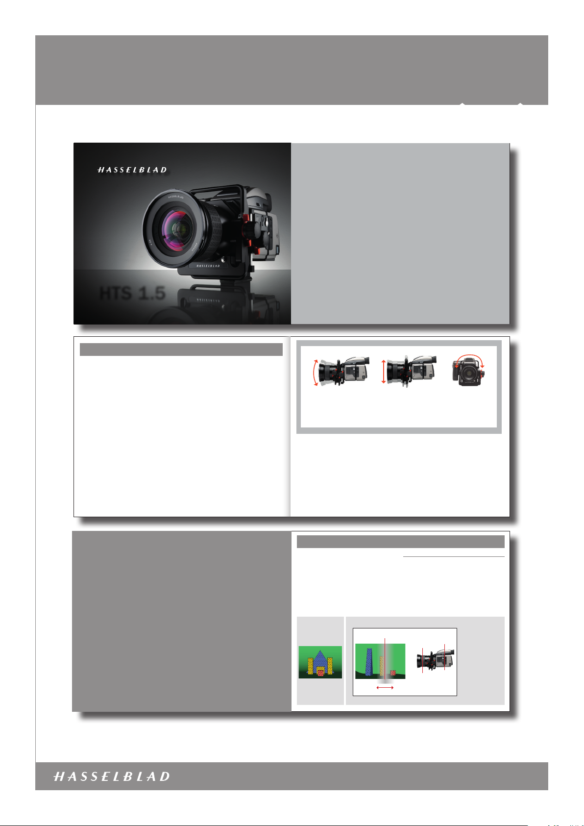
20º
total
Tilt
Tilt changes the orientatio n of the
plane of sharp focus. This cr eates
the appearance of an ‘incre ase’ or
‘decrease’ in depth of field.
Compatibility
The HTS 1.5 was speci cally designed for use with the H CD
4/28mm and HC 2.8/80mm lenses, and t hese should be seen
as the primary ch oice for maximum perfor mance. However, the
HC 3.5/35mm, HC 3.5/50mm and HC 2.2/100mm le nses can
also be used with excellen t results. The 13mm, 26mm and
52 mm extension tubes are a lso compatible with all of these
lenses. The HC 3.2/150, HC 4/210 and HC 4.5/300 can also
be used but handling an d performance are comp romised and
are therefore not recommended for critical work.
Please note that the HT S 1.5 is not compatible with the
H1.7x converter, CF lens adapter, HC 3.5- 4/50-110mm, HCD
4-5.6/35-90 mm, or the HC 4/120mm Macro.
The autofocus and fo cus conrmation features on t he camera
are also automatical ly de-activated for all le nses.
36mm
total
Shift
Shift allows perspe ctive control
by preserving parall el lines in the
image. It also allows ‘stitched ’
panoramas.
USER MANUALS
5
180º
total
Rotation
Allows the whole unit,
at any tilt and shift settings, to be rotated for
further control.
The integral conve rter in the HTS 1.5 alters the ang le of view
(in effect, exte nding the focal length) of each le ns and causes
some loss of speed. Fo r example, a HC 2.8/80mm - HTS 1.5
combination will pr oduce an image you might expect f rom a
4.5/128 mm lens on its own, as a rough guid e. Please see
under Specications for full details.
For the HTS to function c orrectly, the rmware in the came ra and Phocus soft-
ware must be recent. Please en sure you have the latest versions inst alled. You
can download them free of char ge from:
http://www.hasselblad.com/service--support/technical-support/software-downloads
2
TI LT
– a basic explanation
A classic problem in close-up pro duct
photography and similar areas, is the lack
of depth of eld.
Using tilt can solve many such problems
as well as offering creative solutions.
3
Basic explanation of tilt
With a basic understan ding of the principles behind
tilt and shift, you will ga in more confident control of
the HTS 1.5 and be abl e to exploit its potential to the
optimum.
The function of a ca mera lens is to project an image onto a s ensor. The sensor, being effec tively two dimensional and lyin g in a
specic plane, can o nly record a two dimensional at p lane, in
the same orienta tion, in the subject.
In practice we nor mally perceive some areas in fr ont and behind
this at plane in the sub ject as “sharp” and this is termed the
depth of eld (which in it s turn expands or contracts a ccording
to aperture set ting and subject distance).
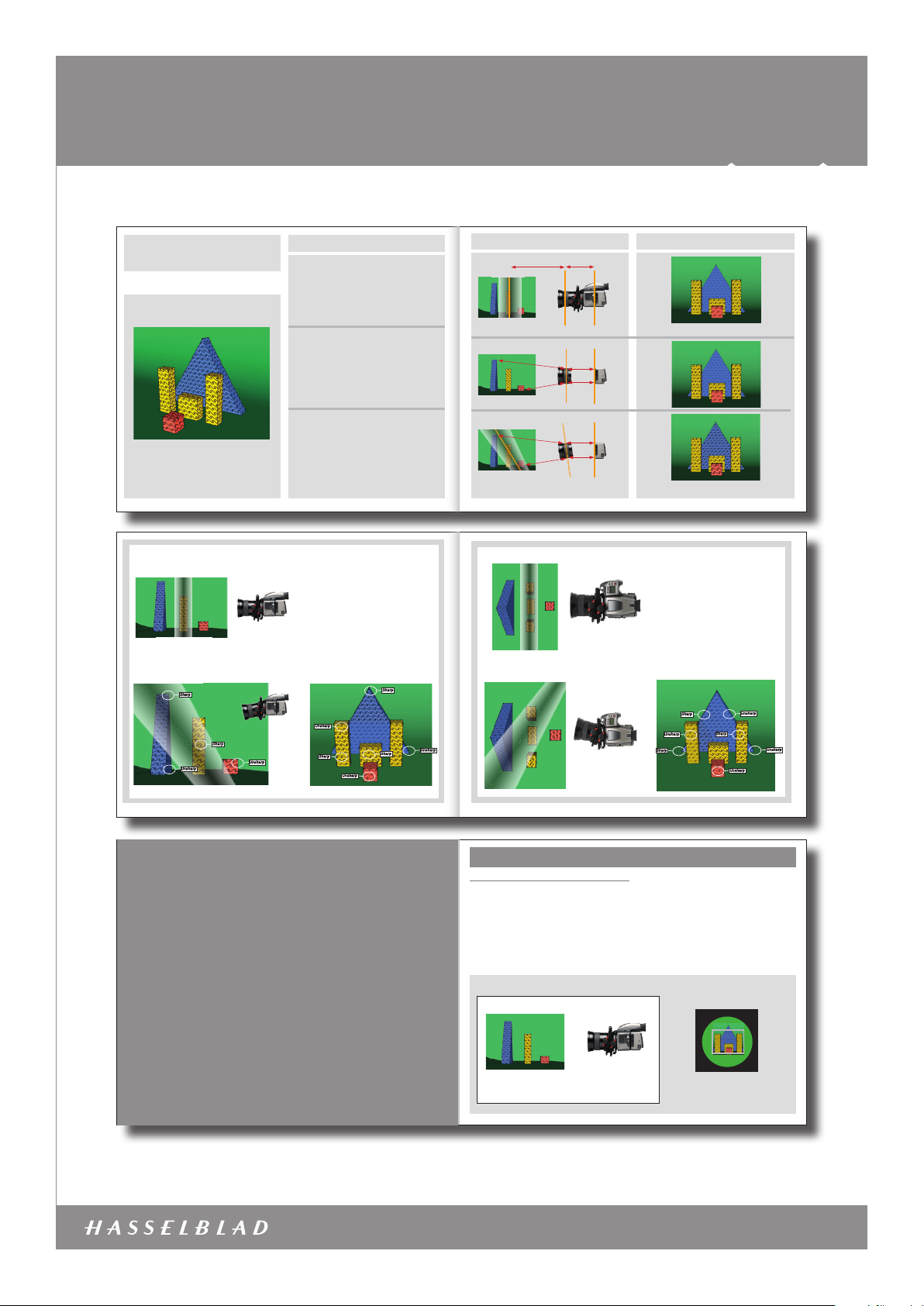
Original scene
from camera
viewpoint
Tilt
1/8
Subject plane
Depth of field
Tilt
The lens is normally se t perpendicular to the image plan e and
therefore is eff ectively in parallel with the se nsor as well. This
provides three pl anes to consider – the sensor, the lens and th e
subject – all paralle l. They are also interrelated, so movin g one
will have an effect o n the others. This is where tilt is intr oduced.
In the diagram below, th e image plane, lens plane and subjec t
plane are parallel. Th is creates an area of acceptable s harpness – the depth of el d. In this case, not all of the subject
lies within the bound aries of the depth of eld and those p arts
therefore appea r unsharp. By tilting the lens it is pos sible to
include more of the ob jects in the depth of eld witho ut having
to use a smaller aper ture.
In this case, the lens is
focused in front of the
Image (sensor) plane
Lens plane
4
yellow object.
At the given aperture
setting, the yellow objec t
is covered by the depth
of field, the red object
partly covered and the
blue object not covered
at all. The yellow object
will therefore be acceptably sharp, the red object
partly sharp and the blue
object unsharp.
www.hasselblad.com
HTS 1.5 – 30 4340 0 – 2011 – v3
Page 2
HTS 1.5
Item no.: 3043400
USER MANUALS
Fig. 5
Inside the camera
A
C
E
C
E
Fig. 1 Fig. 1
B
Fig. 2 Fig. 2
F
D
Fig. 3 Fig. 3
F
D
6
TILT
Original scene
Fig. 4
Sharp
Sharp
Unsharp
Unsharp
Camera angle and lens movement
Fig. 1
In this diagram, a f ocus setting has been mad e for
the yellow object at di stance A. This in turn pro duces
a specific ‘lens to s ensor’ distance B.
The relationshi p between these two dist ances is
reciprocal; alt er one and you must alter the other t o
maintain sharp focus.
Fig. 2
In this diagram, i f distance C is now altered so t hat
the blue object is sh arp, then distance D will be
altered accordi ngly. Likewise E and F.
Only millimeter s of difference in dista nce are required
from lens to sensor t o create great changes in sub ject
to lens focus dis tance and this is why tilt beco mes a
possibility.
Fig. 3
When tilting the le ns, distance D is decrea sed, allowing focus for the lon ger distance C. Similarly, F ha s
now increased allow ing focus for the shorter di stance
E. Consequent ly, the red object has the requi red sensor to lens distanc e for correct focus and so has t he
blue object, the reby allowing them to be both shar p at
the same focus set ting without any need to alter t he
aperture sett ing.
5
In this diagram, the lens is foc used on the yellow objects. At the widest aper ture only the yellow objects are
covered by the depth of field.
This situation illustrates t hat producing sharpness in
certain parts of t he subject can produce unsharpness
in other parts of the image.
Note that the vertical obje cts show a varying amount
of sharpness according to he ight as well, not only distance from the camera as migh t normally be expected.
You should be aware of this possibili ty occurring. In
this particular case , if the yellow objects were one solid
object, it might hide the unsharp s ection of the blue
object to produce apparent sh arpness over the whole
image.
Sharp
Unsharp
Sharp
Sharp
Unsharp
continued overleaf
continued overleaf
continued overleaf
Unsharp
Result
Only the yellow objec ts are sharp
All the objects ar e now much sharper
In this diagram, the lens is foc used on the yellow
objects. At the widest ape rture only the yellow
objects are covered by the de pth of field.
When the lens is tilted, the plan e of the depth of
field tilts. The left sid e of the blue object is now
sharp and the right side unsharp. The le ft yellow
object is unsharp while the right ye llow object
remains sharp.
Note that in this case, as oppo sed to the previous
situation illustrated, the shar pness of each object
is not affected by its he ight.
Sharp
Unsharp
Sharp
Unsharp
Sharp
Unsharp
Unsharp
7
SHIFT
– a basic explanation
A classic problem in architectural work
and similar is the preservation of parallel
elements in the subject when the camer a
angle has to be moved.
Shift also allows the creation of ‘stitched’
panoramas.
9
Basic explanation of shift
Shift
The image from the le ns is focused and projected insid e the
camera onto the sen sor. Normally, this so called ‘image circle’
is just large enough to c over the sensor. However, the integral
converter in the H TS 1.5 enlarges the image circle. This allo ws
parts of the ima ge to be projected outside of the s ensor area.
These parts wo uld not normally be recorded bu t would nevertheless remain accessible.
If the lens is shifte d, the projected image will conse quently
move, allowing the previ ously unrecorded part s of the image to
project onto the se nsor and thereby be recorded.
Shift
Tilting the camera upwards to in clude the top
of the blue object would make the par allels in
the yellow objects converge.
2/8
8
Shifting the len s allows the camera (image plane and l ens
plane) to remain parallel to t he subject. This prevents any pa rallels in the subject fr om converging as would normally b e the
case if the camera w as just pointed upwards.
View of inside the ca mera
(In reality the projecte d image would be
inverted)
The enlarged image circle is pr ojected onto the
sensor (represented by the grey r ectangle).
In this case, part of the i mage lies outside the
sensor.
10
www.hasselblad.com
HTS 1.5 – 30 4340 0 – 2011 – v3
Page 3
HTS 1.5
Item no.: 3043400
USER MANUALS
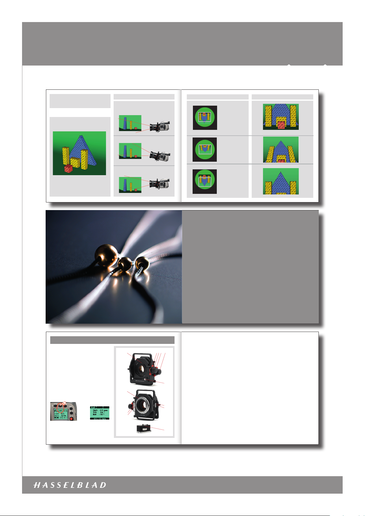
SHIFT
Original scene
Camera angle and lens movement
Fig. 6
Camera is levelled an d aimed
directly at subj ect.
No lens movement.
Fig. 7
Camera aimed up at sub ject. No lens movement.
Fig. 8
Camera is levelled an d aimed directly at subjec t.
11
continued overleaf
continued overleaf
Lens shifted up wards.
continued overleaf
Inside the camera
Fig. 6 F ig. 6
The enlarged image c ircle
is projected ont o the sensor (grey rectangle).
Part of the image lie s
outside the sens or.
(In reality the pro jected
image would be inverted)
The top of the blue obje ct
is now projected on to the
sensor but the vert icals
have converged.
After returnin g the camera
to the level positio n and
shifting the len s upwards,
the projected inverted
image moves upwards , allowing the top part of t he
subject onto the se nsor.
The verticals remain paral-
lel in the result .
Fig. 7 F ig. 7
Fig. 8 F ig. 8
12
Result
Getting Started
The HTS 1.5 is very simple to use. The
high level of integration within the system
makes it almost seamless in operation.
Getting started
User parts and components
1. Lens alignment index 7. Alignment index
2. Tilt lock 8. Shift scale
3. Tilt adjustment kn ob 9. Shift scale indicator
4. Shift lock 10. Til t scale
5. Shift adjustm ent knob 11. Tilt scale indicator
6. Lens release button 12. Mount extender
Attaching and removing
The HTS 1.5 is attach ed to the camera in the same mann er as
mounting a lens, matchi ng the alignment index 9 with the in dex
on the camera bod y. The lens is mounted onto the adapter in
the same manner, matching t he alignment index 1. The lens and
adapter can be mount ed singly or combined. Removal is eit her
singly or combined usi ng the lens lock (6) on the adapter and the
lens lock on the camer a body in the conventional mann er.
Attaching the HTS 1 .5 displays a new screen on the camer a
grip to indicate the HT S button. When pressed, it w ill bring up
the HTS screen on the d isplay showing the movements’ data,
namely, shift in mm, tilt and r otation in degrees.
➡
HTS 1.5 settings
Shift and tilt movem ents have click stops for zero sett ings and
are lockable. Rotati on has clickstops for each 15º but can be
set at any angle up to 90º cl ockwise or 90º counter- clockwise.
The shift and tilt ad justment knobs are released by r otating the
13
1 2 3 4 5
7
8
9
15
14
locks (2 and 4) in a counter-clo ckwise direction. The adju stment
knobs are then rota ted in either direction until the d esired position is achieved and the n secured in place by rotating th e locks
in a clockwise direc tion.
The amount of shift a nd tilt adjustment can be read of f the
scales (7 and 10) by the indicat ors or the camera grip display.
Note that settings m ade according to the clickstops o r the
scales are very clo se but approximate. For example, wh en tilt
has been zeroed by the cli ckstop, the reading on the grip may
be displayed as 0.4°. Please note theref ore:
For critical use, always che ck the settings on the camer a grip display.
All movements data is au tomatically stored with eac h individual
le and can be later viewe d in Phocus.
It is good practice t o ensure that both shift and tilt h ave been
6
10
11
12
zeroed before you st art work. There is no indicat ion in the viewnder display regardi ng the amount of movement set and it is
not always obvious just by l ooking at the image in the view nder. Also, check the orientat ion of the adapter, making sure it is
capable of tilting or s hifting the lens in the desired d irections. In
the case of architec tural/documentary photogr aphy or similar it
would also be advisabl e to level the camera in all planes befo re
work begins.
Remember when using sh ift that the equipment in us e will have an effect on
results. Smaller sen sor models will allow more m ovement and lm magazines
(because the lm area is greate r) will allow less less moveme nt to exploit
before vignetting becomes noticeable.
A 90° clockwise rotation is not possible i f a GIL (GPS accessory) unit is at tached.
Camera settings
There is no need to make any sp ecic camera settings. You
may, however, wish to make a new user prole f or the sake of
convenience. For examp le, you might want to set the button s at
the rear of the grip to Sto p Down and Mirror Up for easier thumb
access (see following se ction for details). Autofocus and fo cus
aid are automatically inactivated.
3/8
Lens settings
Focus is manually cont rolled while shutter and aper ture settings
are controlled in the c onventional manner from the ca mera (or
Phocus, if tethered).
Exposure settings
For optimum accur acy, exposure should be measured wit h shift
and tilt set at 0mm and 0°. You will note tha t when movements
are more than 1mm or 1°, the exposure inf ormation is no longer
visible in the viewf inder. This information immediate ly returns,
however, when the movement s are zeroed again.
The preferred met hod is therefore Manual or using Au to and
then locking the rea ding. Shift and tilt changes c an be made
without altering t he exposure settings again as the H3 D II takes
such movements into ac count. If, however, lighting is altered,
then for accurate ex posure readings, movements will hav e to be
set back to zero and a new rea ding taken.
Particular at tention to consistent exposure set tings should be
shown when using shif t to 'stitch’ shots, in order to avoid post–
production problems.
Technically, any alteration of se nsor to lens distance demands
a corresponding exp osure compensation (as takes plac e during
tilting) but the cam era assesses the data from t he HTS 1.5 and
makes the necessary compensation automatically.
Mount extender
The mount extender i s attached to the camera foo t by inserting
the positioning pin on t he extender into the recess in t he quick
coupling plate on the c amera and rotating the retai ning screw
clockwise into pla ce. The mount extender creates cl earance
from the tripod/stand he ad to allow for free rotation of the un it.
Storage and transportation
It is recommended t hat you store the HTS with zero movem ents
in the supplied case. Avoid l eaving the HTS for long periods w ith
extreme movement s ettings, particularly in v ery hot conditions,
for example, in a closed car in t he sun. Occasionally check the
optics for dust or mar ks, treating the glass surfa ces with the
customary precautions.
16
www.hasselblad.com
HTS 1.5 – 30 4340 0 – 2011 – v3
Page 4

HTS 1.5
TILT AND SHIFT ADAPTER
USE OF TILT
By tilting the lens in relation to the image plane, you can effec-
tively tilt the plane of sharpness in the subject. Depending on
your idea of the nal image you can either use tilt to enlarge the
apparent depth of eld or reduce it.
The full image
TILT AND SHIFT ADAPTER
Item no.: 3043400
USER MANUALS
Approach
Whether solving a p roblem or creating an effec t, a simple initial
analysis of the situati on is advisable, particular ly in regard to
tilt.
The key with tilt is to esta blish where the plane of focus alrea dy
is in the set-up and subj ect, and where you want it to be. Only
then can you make the app ropriate corresponding m ovement.
This applies to both cor rective action (to ‘increase’ the d epth of
eld) and to selective f ocus situations (to ‘decrease’ the dept h
of eld).
Shift is much easier to e stimate as results are obvious. How ever, a combination of tilt and s hift can introduce new cons iderations in cert ain circumstances. See unde r Specications
for details. Likewise, rot ation will also introduce a slightl y more
complicated situa tion to arise.
While it would be possib le to work out which movements to use
with charts and m athematics, a visual check has to b e the nal
point of judgement. V iew camera users have various met hods
of working (see Scheimp ug principle, for example) and you
might nd that a simpli ed version of this concept is enoug h for
everyday use.
The main point to remem ber is to keep a careful check on all
parts of the imag e because increasing sharpne ss in one part of
the image can create un sharpness elsewhere.
Tilt – in practice
With some imagination, tilt can both
Avoiding problems
•Ensurethelatestrmwareisinstalledinthecamera.
• Read the recommendations regarding l ens choice to be
aware of the limitatio ns with certain models and ac cessories etc.
• Forcriticaluseproceedasfollows:
Move the lens upwards (or fr om the left to the right when
tilting sideways) into the zer o postion and then lock
it.Ensurealsothatthecameragripdisplayindicates0°.
• Checkforpossiblevignetting.
• Somecombinationsand /orconditionsmightproduceslight
color casting. See t he Phocus manual (Lens Corrections >
Custom White) for solutio n.
• Afterusingtilt,carefullyre-checkfocusoverthewholeof
the image.
17
solve a number of problems and also
create a number of new directions.
19
1
4
7
10
13
2
MENU
5
F
8
ISO / WB
Save
11
F
14
R
3
F
6
F
9
F F
12
R
PROFILES/ESC
15
F
ISO / WB
Enter
R
ON•OFF
ISO / WB
Save
Tilt - in practice
Tilt, to solve problems
A classic problem in clos e-up product photog raphy and similar
areas, is the lack of dept h of eld. Using smaller apertures i s
of course the stan dard solution but using very s mall apertures
can degrade the i mage because of optical diff raction. Additionally, there might not be enou gh light to produce the ideal ISO/
shutter speed/aper ture setting choice for the g iven situation.
An undesired comp romise in sharpness, therefor e, often has to
be accepted.
As seen in the previo us diagrams, tilting the lens can all ow near
and far objects to b e in focus at the same time, without r esorting to very small aper ture settings. Consequ ently you can avoid
degrading the ima ge through diffractio n and probably obtain
sharpness that mig ht not have been possible anyw ay.
With regard to the co ncept of depth of eld, however, you are
advised to read a fulle r explanation under ‘Terminolog y’ to gain
a better underst anding of what to expect from th e HTS 1.5 and
how to exploit it to the full est.
Tilt, in use
At rst sight, it migh t appear that tilting the lens shou ld solve all
problems, but this is not n ecessarily the case. As seen in t he illustrations, a narr ow depth of eld when reoriented c an exclude
parts of objec ts that were included before. In t he example given
it would theoretic ally be possible to create an image wh ere only
the lower parts of a ll three objects are sharp, leav ing the upper
parts unsharp.
It is therefore not just a m atter of objects being at var ious
distances from th e camera but in what ‘plane’ they are ly ing as
well. You should be aware of this oc currence and keep a careful
check on all part s of the image when applying movem ents.
Make an HTS profile
You can make a special prole t hat lets the two most often
used actions (for examp le) in this situation - Stop Down and Mir-
rorUp-bemoreeasilyaccessiblebyreassigningtheAE-Land
User buttons on the r ear of the grip.
1. Press the Menu button on the c amera grip.
2. Turn the front control whee l until Settings appear s.
3. Pr ess Enter (ISO/WB button).
4. Turn th e front control wheel unt il Custom Options appear s and press
Enter (ISO/WB button) again.
5. Turn the front control wheel until User Button function (Custom Option
#4) appears.
6. Turn th e rear control wheel to se lect Stop Down.
7. Press Save (or half p ress the shutter re lease button) and press the
Menu button again.
8. Turn th e front control wheel unt il Settings appears an d press Enter
(ISO/WB button).
9. Tur n the front control whe el until Custom Options appe ars and press the
Enter again.
10. Turn the front control wheel until AE-L (Custom Option #5) appears.
11. Turn the rear cont rol wheel to select Mirr or Up then Save (or half press
the shutter release button).
12. Click on the Proles button.
13. Scroll the rear contr ol wheel to the prole you wa nt to replace and press
Save (ISO/WB button).
14. Turn the control whe els to highlight the X symbol and p ress Sel (AF button) to delete the name.
15. Turn the control wheel s again to highlight each charac ter in turn, pressing the Sel button to save i t. Finally press Save (ISO/WB button).
After loading the H TS prole, you can activate the S top Down
and Mirror Up faciliti es much more conveniently. Changin g the
prolewillreverttheAE-LandUserbuttonsbacktoyouroriginal
settings immediately.
18
Selective fo cus
Another common us e for tilt is selective focus. This allow s you
to isolate a specic pa rt of subject by allowing it to be sha rp
while throwing the re st of the image out of focus. This is nor mal
practice with t he use of large aperture set tings but the effect is
to create a at plane of sh arpness parallel to the camer a.
If the lens is tilted howeve r, the depth of eld also tilts creating a zone of sharpness a t an angle to the camera instead. In
addition this also allows o ther areas to be more out of focus,
increasing the emph asis on the sharper areas. See unde r ‘Creative opportu nities’ for an example.
Selective focus c an often be seen to good use in por traiture.
Emphasisoneyes,forexample,iseasilyachievedbytilt.Experiment with tilting up an d down as well as sideways for differ ent
effects. Ag ain, wider apertures are to be pr eferred so as to
increase the sof tness of the out-of-foc us areas.
20
HC80 + HTS 1.5 at f/11, 10 degrees tilt
HCD28 + HTS 1.5 at f/11
No lens tilt produces some lack of sharpness in the foreground and background, partly due to insufficient depth of
field.
By tilting the len s downwards,
there is very good s harpness
from top to bottom in t his
image.
Stopping down the len s to the
smallest apert ure, instead of
using the HTS, c ould only have
produced a compro mise in
sharpness.
Tilting in combin ation with the
H lens/Phocus integ ral lens correction has prod uced a superb
result.
21
4/8
Lens tilted a few degrees to the right produces an image with perfect sharpness from the foreground to the background.
Lens tilted a few degrees to the left produces an image with an apparent shallow depth of field.
22
www.hasselblad.com
HTS 1.5 – 30 4340 0 – 2011 – v3
Page 5

HTS 1.5
TILT AND SHIFT ADAPTER
TILT AND SHIFT ADAPTER
Camera positioned level. The roof of t he building is outside the area
projected onto the sensor (HC28 + HTS).
The complete camera tilted upwards to include t he top of the
building results in converging vertical lines in the image.
TILT AND SHIFT ADAPTER
any distortion of the subject
perfect images that can easily be stitched together
In the case of Adobe Photoshop CS3, use the following proce-
dure:
• openthethreeimages
• Gotomenu:“File-Automate-Photomerge”
• Clickon“addopenles”andcheck“interactivelayout”
• ClickOK
• Inthe preview thatappears you canchoose to modifythe
layout, but in most cases there will be no need for any manual
interaction.
• Finally click OK and the nal stiched image will be proc-
essed.
If the stitch is not perfect, you can modify the layer masks for
each layer.
TILT AND SHIFT ADAPTER
In the case of Adobe Photoshop CS3, use the following proce-
dure:
• openthethreeimages
• Gotomenu:“F ile-Automate-Photomerge”
• Clickon“addopenles”andcheck“interactivelayout”
• ClickOK
• In thepreview thatappears you canchoose tomodify the
layout, but in most cases there will be no need for any manual
interaction.
• F inallyclick OK and the nal stiched image will beproc-
essed.
If the stitch is not perfect, you can modify the layer masks for
each layer.
Item no.: 3043400
Camera positioned level. The roof of t he building is outside the area
projected onto the sensor (HC28 + HTS).
Shift – in practice
When the subject demands correc t
reproduction without undue distortion,
shift can often be used to prov ide the
ans wer.
In addition, shift allows the oppor tunity
to produce tremendous panoramas t hat
are quick and easy to produce.
23
The camera is levelle d to produce non-converging verticals
but the top of the buil ding
falls outside th e sensor area.
Tilting the camer a upwards
produces converg ing verticals
easily seen here at t he edges.
USER MANUALS
Shift - in practice
Shift – to solve proble ms
The perspecti ve in an image is produced par tially by the angle
of the camera (image/sensor pl ane) to the subject. Altering
the angle often so lves one problem only to create ano ther. The
example here illustra tes a common situation.
When photograp hing a building, the location and le ns availability
do not allow you to photogr aph the whole height. Levelling t he
camera produc es acceptable parallel ver ticals in the image but
does not include the t op of the building.
Pointing the camer a upwards (that is, changing the ang le of the
image plane to the subj ect) to include the missing top sect ion
now produces an una cceptable change in apparen t perspective
(in this case, convergin g verticals).
That is where shif t can provide the solution. Shif t allows you
to move the lens while still m aintaining the same angle of the
image plane to the subj ect which preserves the p arallelism,
thereby solving th e problem.
In practice, by the s ame principle, the lens can also be mov ed
in a sideways directio n, by rst rotating the HTS, to inclu de sections to the left and r ight.
Shift – in use
For most architec tural shots, room sets, interior s and industrial work etc, it is nor mal to level the camera if the goal is to
reproduce ver ticals as non-conver ging and upright in the image.
Ensureboththeshiftandtiltmovementsaresetatzeroinitially.
Shifting the len s does not alter the orientation o f the plane of
focus as tilting does, n either does it alter the focus set ting. Full
attention can co nsequently be paid to what is includ ed in the
viewnder onc e the initial settings have been de cided on.
Horizontal stitching Vertical stitching
18 mm18 mm
Shift – for stitchin g
Stitching is the pr actice of digitally mergin g several images
together seamlessl y. By shifting the lens, the HTS 1.5 pro vides
the opportuni ty of altering the nal image for mat by expanding
the width by 73% or heigh t by 98% compared to the normal format. The great adv antage over normal methods of re -orienting
the camera is that th e perspective appears id entical in all shots
as the lens and subjec t remain parallel to the image plane.
Subjects such as int eriors, architectural and d ocumentation
work all benet by exclud ing perspective distor tion that would
normally be obtain ed by moving the camera angle. In t his way
you gain a highly accur ate panorama effect fro m a standard
H3DII camera with s tandard lenses. Although t he use of a
tripod facilita tes this practice, rst class res ults are easily obtainable from hand h eld shots too. Naturally, exposure set tings
should be kept identic al, if possible, to avoid problems later o n
when matching.
The post-prod uction work on such images in the la ter versions
of Adobe Photoshop is fa st, accurate and automatic eno ugh to
be able to classify t he process as normal proced ure.
In practice the c amera does not have to be level. Also, ther e is
no real need to make thre e individual captures (one center ed,
and one either side) as nor mally the software will choo se the
left and right im ages only if set on automatic in Photos hop.
Nevertheless, f or critical use you might want to co nsider making
the three capture s and then manually choose select ed areas to
include in the nal com bination. See overleaf for an examp le of
stitching.
24
18 mm
18 mm
HCD28 and HTS 1.5 — The three image s above were taken with shift and have been merge d (horizontally) into one image using Adobe
Photoshop CS3 (Photomerge). Even at 100% it i s almost impossible to see where the separ ate files have been stitched together.
The complete camera tilted upwards to include t he top of the
building results in converging vertical lines in the image.
Levelling the camera again
and shifting the l ens upwards
allows the top of the bu ilding
to be projected on to the
sensor.
As the camera is leve l (that
is, the sensor is i n the same
vertical plane as t he building), the vertical s do not
converge.
Final image size:
H3D II-50 — 87 Mpixels
H3D II-39 — 68 Mpixels
Final image size: H3D II-50 — 99 Mpixels
25
H3D II-39 — 77 Mpixel s
26
Creative opportunities
Both tilt and shift can be used, singly or
together, to create creative solutions to
problems or to create creative alterna-
tives for a fresher approach.
27
28
5/8
www.hasselblad.com
HTS 1.5 – 30 4340 0 – 2011 – v3
Page 6

HTS 1.5
TILT AND SHIFT ADAPTER
Item no.: 3043400
USER MANUALS
Creative opportunities
The HTS 1.5 can provid e many opportunities to impro ve a
normal shot. The who le idea of being able to manipulate whe re
the plane of focus in the s ubject lies offers scope f or creative
opportunitie s that are difcult to achieve ot herwise. Although
digital manipulati on can often provide similar ef fects it should
be remembered tha t not all effects can be create d digitally. In
addition, much time a nd skill is often required.
A case in point would be th e appearance of out-of- focus areas
in a selective focus sh ot, for example. Here, the bokeh of the
lens also plays a part i n the creation of these part s of the
image that will produ ce unique imagery difc ult to replicate
digitally in a realisti c manner.
Selective focus
Just as tilt can ‘increas e’ the depth of eld (as demonstrated,
only an apparent incr ease. In reality, a change in angle), it can
also ‘decrease’ the depth o f eld by an opposite action. Tiltin g
the lens ‘the wron g way’ to dene the plane of focus in th e
subject in combina tion with a large aperture se tting creates an
effect that disp lays great emphasis on small, speci c areas.
Longer focal leng th lenses and closer proximit y to the subject
increase the eff ect. The examples here use the sam e focus and
aperture set tings, only the tilt angle, and thereb y the angle of
the depth of eld plan e, has changed.
Tilt and Shift together
There can be many case s where combined problems mig ht
be solved by the combi ned solution of tilt and shift to gether.
For example, an archite ctural detail on a tall building cou ld be
captured to (a) maintain its p erspective by using shift an d (b)
isolated from distr acting details (selective focus) by usin g tilt.
Creatively, the combin ed use can produce some unique r esults.
Note that there are sli ght restrictions regardin g the combination of shift and tilt . Check on the chart shown her e for a rough
guide to combinations t hat will not display vignetting.
In this close up of gift foi l wrap, you can just discern the direction
of the plane of sharp focus and also the d epth of field, changing according to the direction of t ilt. Essentially, the same focus,
aperture setting and lig hting were used for all images; only the tilt
(horizontal) setting was altere d.
In reality, after tilting, t here normally has to be a very slight
adjustment of camera posi tion (and possibly focus), if the same
composition is to be kept. S ome subjects, such as illustrated
here, will therefore show dif ferent reflectance patterns . The difference in appearance of the sp ecular highlights is quite marked in
this particular case.
General
Only the user can judg e what is acceptable in image distor tion compared to a ‘str aight’ shot. What might norma lly be
described as techn ically wrong by one person is cons idered a
creative additio n by another. It is therefore not possible to w arn
against mishap when usin g tilt and shift. It is wise to rememb er
the occurrence s that can take place so that you th en either
induce them or at leas t be aware of them if unrequired.
Integral automat ion built into the whole system preve nts
exposure miscalcula tions from the initial estimati on, so it is essentially only the visu al aspects that need to be of conc ern.
It is advisable to always check f or vignetting. Even when ext reme movements
are not used, sensor size, lter holders, extensio n tubes etc can all combine to
create a situation where vigne tting might occur. See FAQ for mo re information.
This graph shows the m aximum amount of tilt that can be us ed
without vignet ting (without lens accessor ies attached) as a
function of the amo unt of shift used. Format 36×4 8mm.
29
31
10
8
6
4
2
Max tilt angle (degrees)
0
0 5 10 15
Shift (mm)
Landscape mode
Portrait mode
HC80, Extens ion ring and HTS 1.5 — Focus was o n the ring together with a very w ide aperture.
In the top right hand co rner of the images you can compa re how the specular highlight s are recorded accordin g to tilt.
• In A they are out of focus.
• In B they are much more out of focus.
• In C they are shar per.
Likewise you can comp are the apparent depth of fiel d in the center of the image.
• In A, the depth of eld is what you would expect at such close range, extension tube and ver y wide aperture.
• In B, the depth of eld appears to be reduced because the plane of focus is not in line with the plane of focus of that part of the im-
age. However, visual emphasis is now on the small se ction that is in focus.
• In C, the depth of eld appears to be much greater because the plane of focu s coincides with the subject in the middle section.
A B C
30
Appendix
General points
Scheimpug principle
Specications
FAQ
Terminology
32
General points
There are various pr actical points that should b e noted when
using the HTS 1.5 that are n ot necessarily specic to the u nit.
Regarding tilt, the mo st common use is to manipulate the plan e
of focus and thereby th e direction of the depth of eld. Ho wever,
depth of eld has no shar ply dened boundaries. An unsh arp
section of an image ca n look acceptably sharp when r educed
and similarly a sharp se ction can look unacceptab ly unsharp
when enlarged. This is co mmonly experienced today wh ere images can be instantl y checked on the monitor at huge enlar gements. So when tiltin g the lens, be aware that while improv ements can be made, a per fectly sharp image acros s the whole
of the desired eld mig ht not ever be possible. Remember tha t
perception of shar pness can also be subjective an d vary according to the nature o f the subject matter.
As is standard pra ctice, judgement of the image shou ld made
with the appropri ate variables in mind (intended enla rgement/
viewing distance/print dp i/etc).
Also, check the focus mo re often than normal. When th e lens is
tilted, you should expe ct a shift in focus. If you are work ing tethered you will be able to make ve ry accurate checks, but eve n
zooming on the digit al capture unit display will be of great h elp.
Remember that some p arts of the image that were in fo cus at
the outset of the shoo t might not be covered by the plane of
sharpness anymor e when tilting adjustments hav e been made.
This can be parti cularly noticeable with talle r objects in product
photography (see earli er diagrams).
* Zoom into the image of a test shot on the di splay to check
focus when untethered.
* Hand held shots with the HT S are possible (in the right condi-
tions), even for stitching.
* Plan carefully when shooti ng interiors, for example, if you
intend to use stitching and HDR, rememb ering to check for
overlapping details and areas.
* Analyze the situation fir st before making any movements to
ensure the optimal corrective action.
* When using selective foc us, check the quality of the out-of-
focus areas produced by v arious aperture settings.
* The HTS 1.5 uses an integr al optical converter to produce the
much enlarged image circle inside t he camera necessary. This
consequently produce s a factor of 1.5 and so the 28 mm lens
would equate to a 45mm and an 80 mm lens to a 128mm
respectively in terms of e ffective focal length.
* While the performanc e of lenses is extremely good in combi -
nation with the HTS 1.5, it sho uld be remembered that when
shifting, the edge of the pr ojected image is being used and is
naturally slightly inferior to the c entral area.
* When making captures for sti tching, the amount of overlap re-
quired for seamless resul ts will depend on the subject matter
and post production sof tware used. Two is normally sufficient
in many cases but three might be ad visable for complicated
subjects. See speci al section in this manual for details.
* The best results shou ld be expected from the 28 and 80 mm
lenses. The 35, 50, and 100mm c an also be used for excellent results while the 150, 210 and 300 are not r ecommended
for critical use. Other l enses and various accessories ar e
incompatible. See page 2 in thi s manual for details.
* It is a good habit to make a final check ag ainst vignetting
(with the lens stopped down to the sele cted aperture) before
capture.
33
Scheimpflug principle
In this illustration, the sensor plane and lens plane are parallel producing a subject plane that is also parallel.
At the widest aperture the depth of field is ver y restricted.
The yellow objects are in focus as they are on the same
plane, along with some of the red object. The gre en objects are out of focus.
Lens plane
Image plane
Depth of field does not extend to
the green objects at full aperture
6/8
Object in focus
Object out of focus
Subject plane
34
Object out of focus
Out of focus
here
Object in focus
continued overleaf
www.hasselblad.com
HTS 1.5 – 30 4340 0 – 2011 – v3
Page 7

HTS 1.5
TILT AND SHIFT ADAPTER
Movements - rotation
The HTS 1.5 adapter can be rotated 90 degrees
to the left or right to enable free placement of
sharpness plane and shift direction.
TILT AND SHIFT ADAPTER
TILT AND SHIFT ADAPTER
TILT AND SHIFT ADAPTER
0
20
40
60
80
100
0 10 20 30 40
f/11
MTF (%)
Image position (mm)
0
20
40
60
80
100
0 10 20 30 40
f/6.3
Image position (mm)
MTF (%)
HCD 28mm
@ innity
Item no.: 3043400
USER MANUALS
Here, the Scheimpflug principle has been applied to determine optimum angle of tilt.
A line is drawn in parallel with the image plane and another drawn in parallel with the desired subject pl ane. Another line drawn from the crossing point shows the plane
that the lens should be tilted to align with.
Object partially out of
focus
In focus
In focus
In focus
Image plane
Lens plane
Subject plane
Retaining the same wide aperture setting, the r esult is now
very different.
The image plane and lens plane are not parallel and so
produce a subject plane that is not parallel. The yellow
objects are out of focus as they now are beyond the depth
All three planes cross at
this point
Close focus range dat a
CLOSE FOCUS RANGE DATA
Lens Minimum distance Maximum image scale Coverage Exp.reduction
HCD 4/28 mm 0.39 m 1:4.7 23 cm × 17 cm 0 EV
HC 3,5/35 mm 0.54 m 1:6.2 30 cm × 23 cm 0 EV
HC 3,5/50 mm 0.64 m 1:5.7 28 cm × 21 cm 0 EV
HC 2,8/80 mm 0.74 m 1:4.2 21 cm × 15 cm 0.3 EV
HC 2,2/100 mm 0.94 m 1:4.6 22 cm × 17 cm 0.5 EV
COMPATIBILITY
Compatibility
The HTS 1.5 adapter is comp atible with all H System camera s. Support for digital imag e corrections only with Hass elblad CF card
The HTS 1.5 adapter is compatible with all H System cameras. Support for digital image corrections only with Hasselblad CF
based digital captu re products. The HTS 1.5 adapt er is optimally designed for the foll owing lenses:
card based digital capture products. The HTS 1.5 adapter is optimally designed for the following lenses:
Lens Equivalent lens with the HTS 1.5 Angle of view diag/hor/vert
HCD 4/28 mm 6,3/45 mm 71°/59°/45°
HC 3,5/35 mm 5,6/55 mm 59°/49°/37°
HC 3,5/50 mm 5,6/75 mm 44°/35°/27°
HC 2,8/80 mm 4,5/128 mm 27°/22°/16°
HC 2,2/100 mm 3,5/155 mm 23°/18°/14°
The HC150, HC210 and the HC30 0 will t onto the adapter but handlin g and performance can be c ompromised.
The HC150, HC210 and the HC300 will t onto the adapter but handling and performance can be compromized.
The HTS 1.5 is not compatible with:
The HTS 1.5 is not compatible with:
The H1,7X converter
The CF lens adapter
HC 50-110 mm
HCD 35-90 mm
HC 120 mm
Autofocus / focus conrmation (disabled)
Depth of field spreads
out from the crossing
point
of field that is in the same orientation as the subject plane.
The front of the red object is now completely in focus a s
well as the green objects.
In reality, the depth of field spreads out from the cro ssing
point and in this case might cover the upper yellow object,
as illustrated here.
35
37
Object out of focus
Specifications
General Lens data:
Focal length c onversion factor 1.5x
Aperture red uction -1.3 sto ps
Width/Heig ht/Depth 140 mm / 146 mm / 77 mm
Weight 750 g
Lens design
6 elements in 5 groups
Entrance pupil position
W. HCD 28mm: 175 mm
W. HC 35mm: 192 mm
W. HC 50 mm: 177 mm
W. HC 80mm: 119 mm
W. HC 100mm: 109 mm
In front of the image pla ne (at innity focus setting).
The entrance pup il position is the correct posit ion of the axis
of rotation when mak ing a panorama image by combinin g individual images of a scen e.
MTF performance
10, 20 and 40 lp/mm
The diagram shows len s performance over the
full enlarged image cir cle.
Vertical dashed line s show the basic sensor
format (36×.48 mm).
Dashed lines in the diag rams show the tangential performance.
HC 35mm
@ innity
HC 50mm
@ innity
HC 80mm
@ 2m
HC 100mm
@ 2m
HCD28
HC 35
HC 50
HC 80
HC 100
36
f/5.6
100
80
60
MTF (%)
40
20
0
0 10 20 30 40
Image position (mm) Image position (mm)
f/5.6
100
80
60
MTF (%)
40
20
0
0 10 20 30 40
Image position (mm) Image position (mm)
f/4.5
100
80
60
MTF (%)
40
20
0
0 10 20 30 40
Image position (mm) Image position (mm)
f/5.6
100
80
60
MTF (%)
40
20
0
010203040
Image position (mm)
38
f/11
100
80
60
MTF (%)
40
20
0
0 10 20 30 40
f/11
100
80
60
MTF (%)
40
20
0
0 10 20 30 40
f/11
100
80
60
MTF (%)
40
20
0
0 10 20 30 40
f/11
100
80
60
MTF (%)
40
20
0
010203040
Image position (mm)
FAQ
I was shooting produ cts close-up. The f oreground object wasn’t
sharp so I tilted the le ns as suggested. It be came much sharper
but the top of it becam e unsharp! How can that be? What did I
do wrong?
Fig. 3 shows what pro bably happened. As you tilt the l ens, the
plane of focus tilts to o. In this case, as the angle did not completely coincide wit h the angle of the plane that the o bjects were
on, it covered the bot tom of the object but not the top. On e solution would have been to use a s maller aperture. You might also
have noticed that th e object at the back might have be en sharp
at the top but unsharp at t he bottom, as in the diagram.
I was using select ive focus but didn’t like the loo k of the out of
focus sections . Can I alter them in some way?
The out of focus areas ar e a result of several factors: the
aperture set ting, the proximity of the subj ect, the nature of the
background, th e bokeh of the lens, etc., some of which can be
changed. Try adding sp ecial effects lters too or a di gital merging of straight and l tered shots.
I want to produce the ma ximum quality from one came ra position to make a huge enlar gement. How can I do that?
Very much dependin g on subject matter, you could tr y making a
mosaic of overlappin g images using shift vertic ally and horizontally. This would involve chan ging the orientation of the c amera
a little though an d so would introduce some distor tion issues
and consequently s ome blending issues in the nal image. N evertheless, using s hift should produce a marke d improvement on
the standard met hod.
Some of my images have vig netted. Why is that?
Tilting and shift ing to the limits puts demands on t he lens and its
ability to cover evenly, in par ticular when combined. S ee the table
in this manual (under Creat ive Opportunities) for rest rictions.
Objects in front of t he lens (lens shade, lter, accessor y holder
etc)canaffectresults.Evenobjectsbehindthelens,suchas
when using extension tu bes increases the chances of blo cking
some of the light rays.
Using a camera with a sm aller sensor or with a lm magazine
will also have an effec t because the capture area dif fers in size
and its placement wi thin the image circle will be altered .
The simplest solutio n is to always make a nal check with the
lens stopped down to t he chosen aperture with all ac cessories
etc in place, before cap ture. When using a lm magazine, you
also have the oppor tunity of using the Multi Contr ol facility of
the camera body r ear protection cover.
In a selective focu s shot I found it difficult to c ontrol the
amount of out-of -focus areas over the who le of the image. Why
is that?
Look at Scheimpug p rinciple illustration to see wh ether the
depth of eld was in fac t expanding as the distance fro m the
camera increase d. In these instances the depth is n ot parallel
as might be expected .
I’ve seen referen ces to “rise and fall” and “swi ng” movements
regarding large f ormat cameras. What are they and w hat do
they do?
Basically, ‘shift’ equa tes to ‘rise and fall’ and ‘tilt’ equat es to
‘swing’ when these move ments are rotated 90°.
Large format cam eras are provided with these ex tra movements
partly to avoid hav ing to mount such a large camera at 9 0°. The
HTS can be turned as a uni t, thereby avoiding this parti cular
need. Further more, as the unit can be rotated fre ely, it provides
the opportuni ty to effectively combin e movements. For example,
tilting the lens with a 4 5° rotation is, in effect, prod ucing a
partial swing.
Can I use extensio n rings?
Yes. They are all compatible. Jus t remember to check against
vignetting.
39
Terminology
Perspective (apparent perspective)
The appearance o f perspective in an image is the re sult of a
number of factors i ncluding angle of view, focal leng th of the
lens, proximity to th e subject etc, and is sometimes ter med
apparent because i t only appears that way in the ima ge in those
circumstances.
Depth of field
Simply put, depth of eld describes the amount of the s ubject
that is perceived as a cceptably sharp. It is measured f rom a
calculated distan ce in front and a calculated dista nce behind
the point of focus (subjec t plane). It essentially expands and
contracts acc ording to the point of focus and ape rture setting
when in parallel to the im age plane. That is to say, the closer
the subject is to the c amera, the less the depth of eld wil l be
and the smaller the ape rture, the greater the depth o f eld will
be and so on, with all possi ble combinations in between.
In addition, the ‘wid th’ of the depth of eld expands the f urther
it is away from the came ra. See g. 4 where it is so narrow
that the top of the red ob ject is not included and therefo re not
perceived as sharp, d espite it being so close. Note that tilt ing
the lens does not increas e or decrease the depth of eld, it on ly
alters its orient ation and shape.
It should be strongl y emphasized that in practica l terms the
perception of wha t is termed “acceptably sharp” can v ary a
good deal depending o n magnication, resolutio n, media etc
and should by no means take n to be an absolute. Depth of eld
should therefore be s een as a relative term and is best judg ed
subjectively whe n all variables are taken into consid eration.
Depth of eld tables s hould be interpreted with this in formation
in mind and seen as guides.
7/8
Image circle
All lenses project a ci rcular image termed an “image circle”.
This has to be large enoug h to cover the whole of the sensor to
achieve a full image and avo id vignetting at the corner s of the
sensor frame. The int egral converter in the HTS 1.5 en larges
the image circle enou gh to allow the lens to be shifted fro m its
central position w hile still projecting an image on t he sensor.
Image plane / sensor pl ane / film plane / plane of focus
The plane of focus is the p oint in a camera where all the light
rays converge to crea te a sharp image. It is often referr ed to as
the lm plane or more re cently sensor plane.
Bokeh
Bokeh is the perceive d quality of the out of focus areas i n an
image, caused by the con guration of the elements in a lens.
Its appearance c hanges according to apertu re setting, focus
setting and foca l length. The bokeh could be par ticularly apparent when using sele ctive focusing with the HTS 1.5 a nd
contributes to the s ubjective quality of those ar eas.
Scheimpflug principle
This rule can be applie d simply and rapidly to nd a good sta rting point for tilt calc ulations. It helps to optimise the situ ation
but it does not increa se or decrease the depth of eld. S ee
explanatory dia gram in this manual.
40
www.hasselblad.com
HTS 1.5 – 30 4340 0 – 2011 – v3
Page 8

HTS 1.5
41
The information in this manual is fur nished for informational us e only, is subject to change
without notice, and should not be constru ed as a commitment by Victor Hasselb lad AB &
Hasselblad A/S.
The text in this manual cannot be re printed or reused without the exp ress permission of
Victor Hasselblad AB & Hasselblad A /S.
The images in this manual cannot be re printed or reused without the e xpress permission of
the photographers who took them .
Victor Hasselblad AB & Hasselblad A /S assumes no responsibil ity or liabilit y for any errors or
inaccuracies that may appear in this manual.
Victor Hasselblad AB & Hasselblad A /S assumes no responsibili ty or liability fo r loss or dam-
age incurred during or as a result of using Hass elblad products.
Hasselblad, Imacon, Ixpress, FlexColor and Phocus are trademarks of Victor Hasselblad AB
& Hasselblad A/S. Adobe, Ad obe Photoshop is a trademark o f Adobe Systems.
Copyright © 2011
Victor Hasselblad AB & Hasselblad A/S
All rights reserved.
Visit www.hasselblad.com to downloa d user manuals, data-
sheets, product br ochures, technical informa tion, technical
articles, sof tware and rmware updates et c., as well as news
about the latest devel opments at Hasselblad.
Item no.: 3043400
Ce texte dans votre langue?
FRA
Utilisez “Google Translate” sur Internet.
Diesen Text in Ihrer Sprache?
DEU
Verwenden Sie “Google Translate” im Internet.
Este texto en su idioma?
ESP
El uso de “Google Translate” en Internet.
Questo testo nella tua ling ua?
ITA
Utilizzare ‘Google Translate’ su Internet.
Este texto na sua língua?
PRT
Usar “Google Translate” na Internet.
Denna text på ditt spr åk?
SWE
Använd “Google Translate”på Internet.
Deze tekst in uw taal?
NLD
Gebruik ‘Google Translate’ op het internet.
JPN
CHN
IND
RUS
SAU
USER MANUALS
Visit www.hasselblad.com to download user manuals, datasheets, product brochures, technical information, technical ar ticles, software and firmware updates etc.
as well as to read about the latest developments at Hasselblad.
The information in this manual is furnished for informational use only, is subject to
change without notice, and should not be constru ed as a commitment by Victor Hasselblad AB & Hasselblad A/S. The text a nd images in this manual cannot be reprinted
or reused without the express permission of Victor Hasselblad AB & Hasselblad A/S.
Victor Hasselblad AB & Hasselblad A/S assume no responsibility or liability for any
errors or inaccuracies that may appear in this manual. Victor Hasselblad AB & Hasselblad A/S assume no responsibility or liability for loss or damage incurred during
or as a result of using Hasselblad products . Copyright © 2011 - Victor Hasselblad AB
& Hasselblad A/S. All rights reserved.
8/8
www.hasselblad.com
HTS 1.5 – 30 4340 0 – 2011 – v3
 Loading...