

Harris FM-25K Service Information Supplement
www.SteamPoweredRadio.Com
AUG
2
7
2004
FM-25K
This FM-25K Service Information Supplement
intended
The goals of this manual are to assist you
Service Information Supplement
is
a technical manual
for
use
by
your
transmitter
maintenance
in
getting the best
personnel.
performance from your FM-25K transmitter, and to save you time.
We included "how to" information, and other knowledge acquired
through the experience of Harris service personnel.
Also included
is
some
of
the life history of the FM-25K transmitter
and concise information about updates.
This information
is
grouped alphabetically by section, and then
alphabetically by topi
c.
For a topical reference, please refer to the index.
For help
in
the identification of part numbers, please refer to the
applicable drawing.
R:
\service\Radio\Product Support\
pdf 11 Dec
2001
Copyright Harris
Fm
\Fmseries\Fm25k\
Se
rvice Supplement\Fm25serv 4/25/00
Caution!
This transmitter contains lethal voltages. Use safe working
practices, and make use of the protection devices provided
transmitter.
in
the
www.SteamPoweredRadio.Com
Control
AC
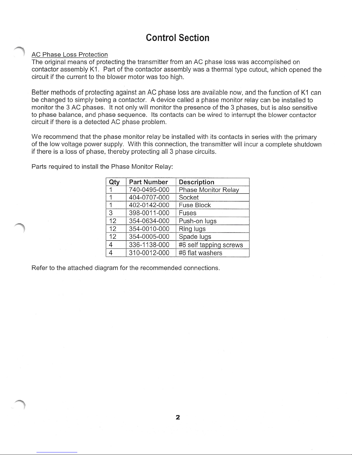
Phase Loss Protection
The original means
contactor assembly K1. Part
circuit if the current to the blower motor was too high.
of
protecting the transmitter from
of
the contactor assembly was a thermal type cutout, which opened the
Section
an
AC
phase loss was accomplished on
Better methods
be changed to simply being a contactor.
monitor the 3
to phase balance, and phase sequence. Its contacts can be wired to interrupt the blower contactor
circuit if there
We
recommend that the phase monitor relay be installed with its contacts
of
the low voltage power supply. With this connection, the transmitter will incur a complete shutdown
if there is a loss
Parts required to install the Phase Monitor Relay:
of
protecting against an
AC
phases. It not only will monitor the presence
is
a detected
of
phase, thereby protecting all 3 phase circuits.
AC
phase problem.
Qty
1
1 404-0707-000 Socket
1 402-0142-000 Fuse Block
3
12 354-0634-000 Push-on lugs
12 354-0010-000 Ring lugs
12 354-0005-000 Spade lugs
Part Number Description
7 40-0495-000 Phase Monitor Relay
398-0011-000
4 336-1138-000
4 310-0012-000
AC
phase loss are available now, and the function
A device called a phase monitor relay can be installed to
Fuses
#6 self tappinq screws
#6 flat washers
of
of
the 3 phases, but is also sensitive
in
series with the primary
K1
can
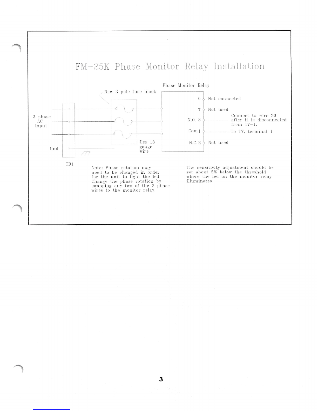
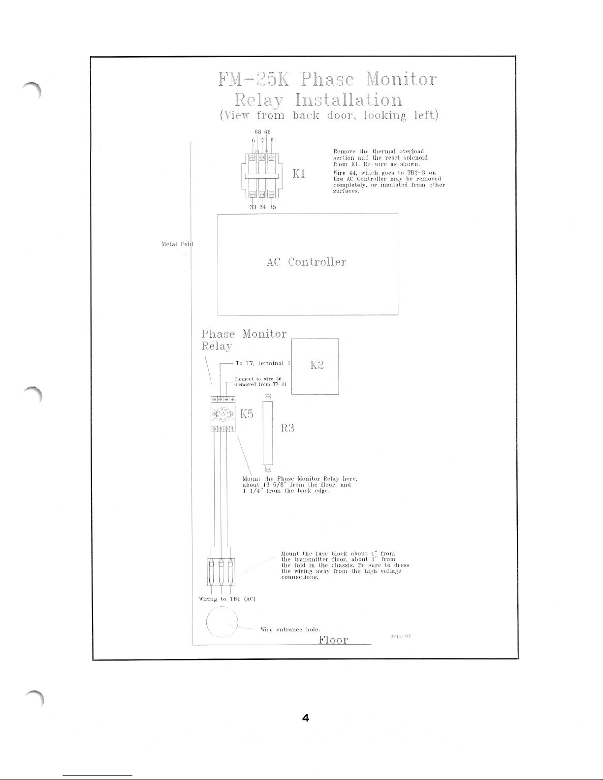
Refer to the attached diagram for the recommended connections.
2
www.SteamPoweredRadio.Com
:3
ph
asP
AC'
In
p
11
t.
·-
·;n
cl
~
-
(
~
TB l
FM
•)i--.K
-
/,
,,
,_)
Pha:~
:e Monitor Relay
In:~
:
talla
tion
/~
PhasP
Mo
ni
to
r Relay
Ne
w 3
po
le fuse
bl
oc
k
-
~
\
(
\
I
<
\
,·
\
!
-
j
\
)
\
-
Use
18
gauge
w
ir
e
Nol.e:
Ph
ase
ro
tati
on
m
ay
n
eed
to
be
ch
an
ge
d
in
o
rd
er
fo r
Lh e
un
it
to
lig
ht. t
he
led.
C
ha
nge
t h e
ph
a
se
rota
ti
on by
,;
wa
ppin
g
an
y two of
t
he
3
ph
ase
wirPs
to
the
monitor
re
la
y.
3
6
J,
I
ot
co n
necte
d
7
J,
No
l.
u
sed
j
Co
nn
el'
! lo wirP
:_\(j
N .
0.
8 ,,__
____
afte
1· it
is
disc·
on
n
ec-ted
j
fl
·om T7-
1.
Com
1 ,
1
~----
To
T7,
term
in
al
1
N.
C'
. 2
'f
Not
w_;ecl
Th e
se
n s
it
ivi
ty
adjust
mt>
nt
,
;l10ul
<I
be
se
l.
abo
ut
5%
below t
he
LhrPsh old
wh
pr e
th
P
l
ed
on t
he
m o
nitor
r
r>
l
ay
illu
m
in
ates
.
www.SteamPoweredRadio.Com
M<"lal Fol I
~A~25
F
Relay
(View
from
AC:
K
Pha:~;e
In:~;tallct
back
Controlln
door
Rcrnove
sec-t
fr om
Wire
the
rnplelel
co
urfaces.
s
.ion
AC
Kl.
44,
,
and
Conl.rnl
Mo
on
ti
looking
l.llf•nu,tl
Uw
n·
hP
1.
wirr as s
fr-
f
l!,Oes
whif·h
r
e'
l
nsulai.ed
i
0 1·
y.
nitor
left)
rJoacl
ove
so)enoid
sel
hown.
TB2-:1
o
!
n~m
he
may
from
on
ove<l
other
Phase
Relay
\
1.o
'il'i11g
\l
Monito
T7
l o
011111.
C.:
\ IPIHOH•cl
\
Momit
about
1
(AC)
TBl
:1
I
1/4"
lo
te
f1nm
,mm,d
1111e
T7-J)
I.he
5/8"
13
from
3H
R3
Phase
r
[:]
1(2
J
Mnnit.o r
from t.he
(~dgt
had.:
i~
I.h
l'u
(~
U1
Mount
trausmit.t
the
e fold in lite ch
t.h
I.h
c·o
e
nn
wiring
di
e
on s.
awa
IH•rP,
ay
J
ffr•
and
r:
oo
fl
!.
fro111
4"
ahout
ock
bl
~c
ahoul
floor,
er
assis.
I.
fro1T1
y
Bf'
he
fro1n
I"
ure
s
gh volt.agf'
hi
to c
ss
ln·
(
Wire e
ulrance
hol
4
e.
Floor
www.SteamPoweredRadio.Com
Air Switch (604-0397-000 )
With age, pressure type air switches eventually lose their ability to sense that there
is
air pressure.
Adjustment can usually restore closure, however, the switch will soon open again. Replacement is
then needed.
Unfortunately, protective devices such
as
air switches often get bypassed
in
the interest of getting
back on the air, then subsequently become forgotten.
For this reason it
is
a good idea to keep a spare air switch
on
hand, and periodically check the air
switch operation.
Check the air switch operation with just the Filaments on. Use a piece of cardboard to block off part
of
the air intake . The air switch should remove the filament voltage when you have blocked off about
half of the
ai
r intake.
The air switch
is
mounted to the side of cavity nearest the Controller housing. The adjusting screw
is
located
in
the center of one side of the switch. Turning the adjusting screw counterclockwise wi
ll
increase the sensitivity (to make the switch close).
If you prefer a more exact method of checking the air switch adjustment, you can insert a manometer
into the pressurized portion of the cavity. Use any of the screw holes that are just below the cavity
shorting deck.
You can make a crude manometer by forming some clear plastic tubing
in
the shape of a "U". Use
enough tubing so that you have a vertical length of about 6 inches per side of the "U".
Put enough water
in
the tubing
so
that the water level is about half way up.
Insert one end of the tubing into the pressurized area. The degree to which the water
is
displaced
between one side
of
the "U" and the other
is
the measurement of air pressure
in
inches of water.
Example: The water level on one side drops 1 inch,
and
the other side raises 1 inch.
The
air
pressure
is 2 inches.
T
he
normal amount of pressure
is
2.5 inches or more. The desired dropout threshold for the air
switch is 2.0 inches.
Digital Logic Board (992-5433-001 )
With older version Digital Logic boards, some have experienced a random control problem wherein
the HV will not come
up
unless you turn the Filaments off, then start the turn on sequence all over
agai
n.
The problem centers around filament flip flop circuit U3B
on
the Digital Logic board. Transient
energy can cause the flip flop to
go
into the wrong state, and it will not be reset without a Filament
OFF command. Impulses that can cause
th
is can come from an AC line transient, a tube arc, or
ot
he
r similar disturbance.
This problem can be reduced or sometimes eliminated by adding a
.01
uF capacitor from TP5 to
g
round
on the Digital Logic board.
5
www.SteamPoweredRadio.Com
A more effective solution
circuit
US.
The newer type Digital Logic board
is
accomplished
in
newer Digital Logic boards by the inclusion of integrated
Interlock Switches
The interlock switches have two poles, one that
solenoids, and one that
is
used to operate the led indicator circuit.
is
a direct replacement for any older versions.
is
in
the coil circuit of the contactors and HV shorting
Sometimes the interlock switch contacts that are
in
the indicator circuit may not close. This creates a situation
open interlock, but
disable the contactors
no
indication to that effect.
so
that the screen and plate supplies do not energize.
in
the coil circuit may open, but the contacts that are
in
In
an FM-25K,
which you have symptoms
an
open interlock
in
the HV cabinet will
In
the Main cabinet, an
of
an
open interlock will keep the blower motor, bias supply, and HV Power Supply from running.
If you experience these symptoms, test the AC side of the interlock switches for closure. This can be
an
done with the power off, using
be
conscious of this possibility. Otherwise, you may defer the problem to another time by not
ohmmeter. Exercising of the switches may clear the problem, so
knowing which switch was the problem.
Power Cutback
Several customers have had a need for a power level cutback function. Typically the reason for this
is
operation
on
a standby AC power generator that
is
unable to handle the normal full power load of
the transmitter.
in
There are various ways to do this, each with their own advantages. The best
is
performance and functionality
to switch variacs
in
the screen power supply. This gives you the
terms of electrical
ability to easily and independently set the two power levels, and yields the most stable operation for
the low power mode.
At the other end of the spectrum in terms of cost
switching another potentiometer
in
the IPA power
is
control circuit.
In
either case, steps will need to
rcu
control ci
it.
be
taken to either disable or accommodate the automatic power
If you have a need for power cutback, you may contact us to discuss your situation and alternatives.
Remote/Local Switching
Depending on whether the remote local switch breaks before it makes, your transmitter might
sometimes trip off when you switch between one mode and the other.
uF
To solve the problem, add a 1
capacitor, Harris part number 526-0050-000, across R99 on the
Analog board.
VSWR Fold back Kit (994-9006-001)
is
Automatic VSWR Foldback circuit
provides the means of automatically lowering the screen voltage
available to retrofit older transmitters. The VSWR Foldback kit
as
the VSWR gradually becomes
too high, then automatically returns it to the normal level as the VSWR problem clears. This is a very
in
useful function
climates and installations affected by the accumulation of ice on the antenna.
Also please refer to the discussion of the Full Range Screen Control.
6

www.SteamPoweredRadio.Com
General Topics
Circuit Breaker Information
in
AC line surges at a few sites necessitated changes
the trip curve of some
you experience random tripping of the circuit breakers listed below, please check yours to see what
trip curve you have. A change
of
circuit breaker type may
be
all that
is
The present breaker part numbers and types for the Main Cabinet are as follows:
of
required.
the circuit breakers. If
CB1
CB2 Bias breaker 606-0827 -000
CB3 IPA breaker 606-0581-000
CB4 Blower breaker
Filament breaker 606-0806-000
606-0581-000
15A, curve 65F
5A, curve 65F
20A, curve 62
20A, curve 62
For the High Voltage Power Supply, the circuit breakers should be:
CB1
Screen breaker
CB2 Blower breaker 606-0552-000
606-0579-000
1 0A, curve
3A, curve 3
61
Frequency change
Changing frequency involves skills and test equipment not readily available at most stations. Several
parts are often required.
If you have a need to change frequency, we can work up
of
includes a list
require. There
components to change, a procedure, and some target values for the power level you
is
a fee for this service.
an
information packet for you. This packet
Incidental AM/Bandwidth Considerations
The basic requirements for good bandwidth are sufficient
heavy loading
of
the PA. There are other contributing factors, but these are the main ingredients
adjustments for good bandwidth as far as the power amplifier
RF
drive to the tube, proper tuning, and
is
concerned.
in
Proper loading
is
with the power output peaked. Going beyond this will sacrifice efficiency.
The power output should also
The IPA reflected power should
A minimum target value for PA grid current
The FM-25K generally has good bandwidth. The exception to this
significantly reduced, but the Plate Voltage
changes.
be
peaked with the PA Tuning control.
be
minimized with the Grid Tuning and Input Match controls.
is
15 to 20 ma.
is
when the power level
is
left at the full amount. See the discussion on TPO
7
is
www.SteamPoweredRadio.Com
Spurs,
AM
lntermod
In
installations where an
FM
transmitter
is
co-located with
an
AM transmitter, it
is
possible that spurs
will be generated that are a product
of
the AM signal mixing with the FM.
In
our experience, this
is
a
result
of
the AM
RF
getting onto the cable between the stereo generator (or STL) and the exciter.
This
is
most likely to happen
in
a system where a balanced composite source
is
feeding a balanced
input.
In
this case, the shield
of
the coax
is
not really functioning as a shield. It
is
more like a pickup
device for the AM signal.
The solution
is
to install a triaxial cable
in
place
of
the composite coax, and ground the shield
of
the
triax.
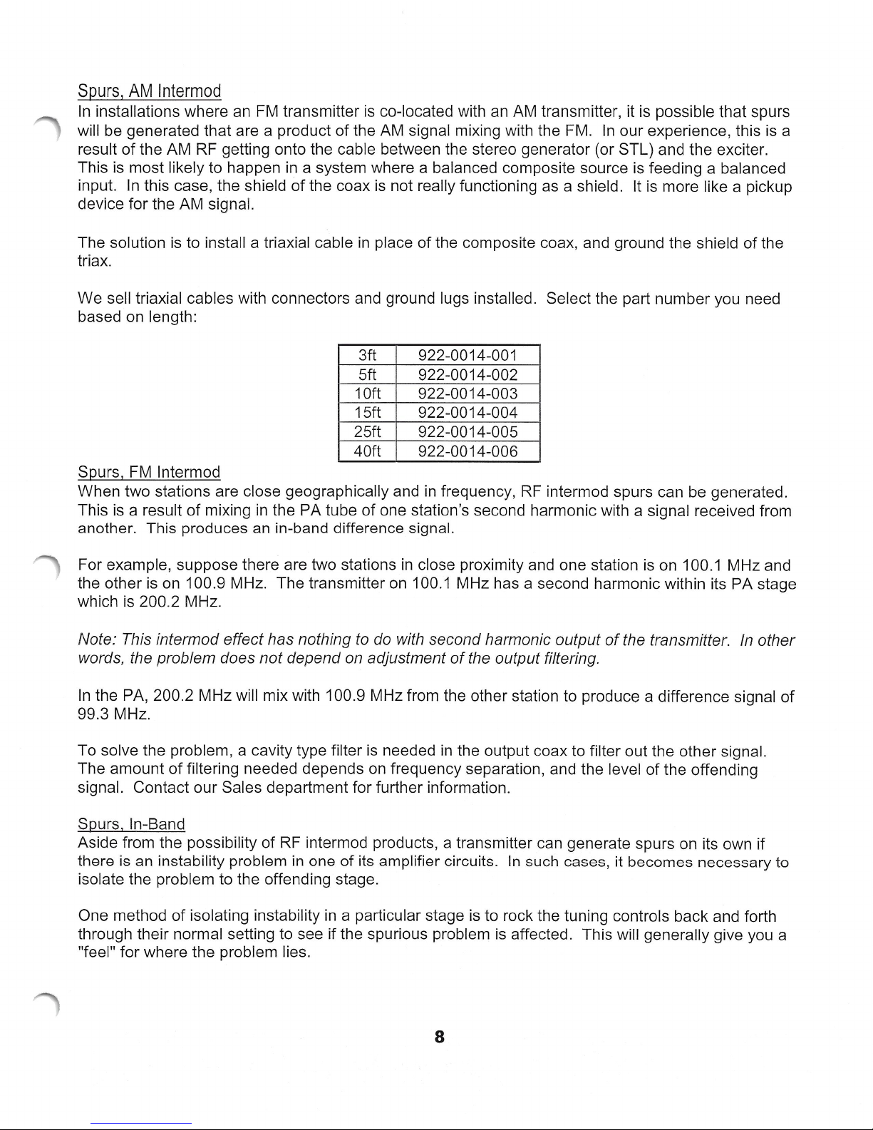
We sell triaxial cables with connectors and ground lugs installed. Select the part number you need
based on length:
3ft 922-0014-001
5ft 922-0014-002
1
Oft
922-0014-003
15ft 922-0014-004
25ft 922-0014-005
40ft 922-0014-006
Spurs,
FM
lntermod
When two stations are close geographically and
in
frequency,
RF
intermod spurs can
be
generated.
This
is
a result
of
mixing
in
the PA tube of one station's second harmonic with a signal received from
another. This produces
an
in-band difference signal.
For example, suppose there are two stations
in
close proximity and one station
is
on 100.1 MHz and
the other
is
on 100.9 MHz. The transmitter on 100.1 MHz has a second harmonic within its PA stage
which is 200.2 MHz.
Note: This intermod effect has nothing
to
do
with second harmonic output
of
the transmitter.
In
other
words, the problem does not depend
on
adjustment
of
the output filtering.
In
the PA, 200.2 MHz will mix with 100.9 MHz from the other station to produce a difference signal
of
99.3 MHz.
To solve the problem, a cavity type filter
is
needed
in
the output coax to filter out the other signal.
The amount
of
filtering needed depends
on
frequency separation, and the level of the offending
signal. Contact our Sales department for further information.
Spurs, In-Band
Aside from the possibility
of
RF
intermod products, a transmitter can generate spurs on its own if
there is an instability problem
in
one of its amplifier circuits.
In
such cases, it becomes necessary to
isolate the problem to the offending stage.
One method of isolating instability
in
a particular stage
is
to rock the tuning controls back and forth
through their normal setting to see if the spurious problem
is
affected. This will generally give you a
"feel" for where the problem lies.
8
www.SteamPoweredRadio.Com
If the problem
number
by the MS and MX-15 exciters. The cause has often been the electrolytic capacitors
drying out.
The life expectancy
be
part
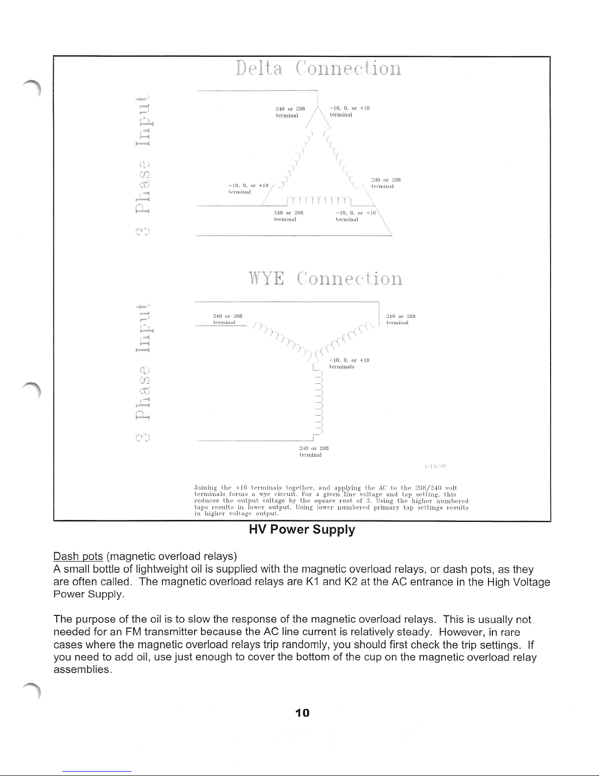
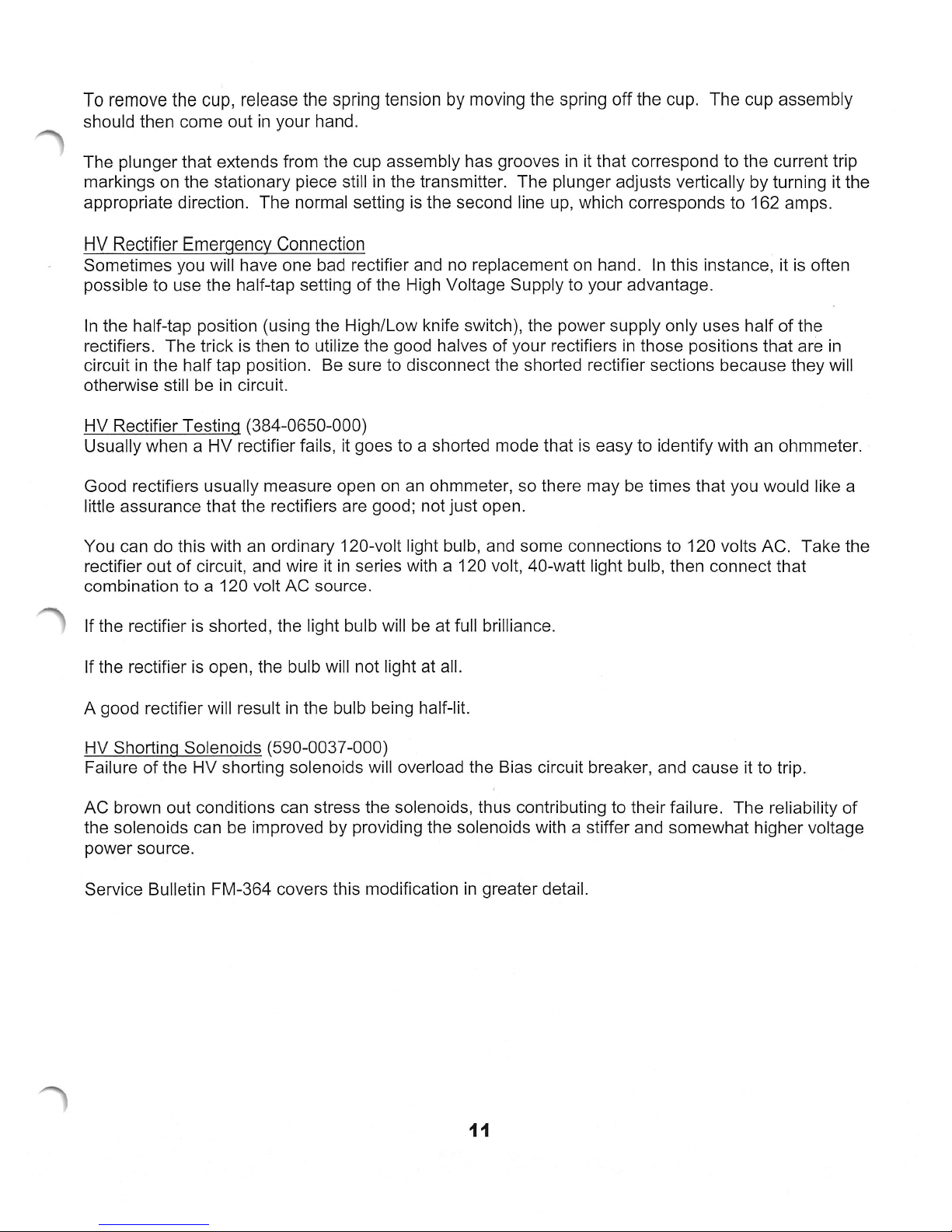
TPO (Transmitter Power Output)Changes
The type accepted power output range for the FM-25K
range, there are various criteria for best operation. For power levels below
HV Power Supply transformer
5300 volts, which will
See the attached drawing
primary
terminals together. The AC wires from the contactor would then connect to the 240 volt terminals.
This would give you the lowest
terminals (208, 0 for example) will give you somewhat higher plate voltage.
For power levels above 10 kW, you will probably have to leave the HV transformer
connection. However, you should connect the primary wires to the highest numbered terminals to
give you the lowest usable plate voltage. Reducing the plate voltage
changing to a lower TPO because it helps accomplish the goal without any sacrifice.
of
replaced if this problem
number
in
is
unaffected by basic tuning adjustments, the problem may
instances we have found that spurs at about 200 kHz or 400 kHz intervals are generated
of
electrolytic capacitors
is
suspected. They are 20 uF,
is
522-0256-000.
in
a wye configuration. This will reduce the Plate Voltage to about
be
a major step
of
the Wye and Delta configurations. To connect the HV transformer
a wye, you would first need to disconnect all the primary connections, then join the +10
vo
in
ltage output. Tapping the transformer to the lower numbered
is
about 10 years, so C8 and C18
50
volt axial lead capacitors. The Harris
is
7350 watts to 25730 watts. Within this
reducing the power and maintaining good performance.
be
the exciter.
in
in
the RF Amp should
10
kW, it
is
your best initial step
is
in
the delta
In
a
the
RF
Amp
best to set the
in
Other handles for power reduction are screen voltage, bias, and IPA power.
9
www.SteamPoweredRadio.Com
Delta ('.onnectio11
-10,
240
OJ' 2flf\
t.e
rmino.1
I
,)
_1
I
j
'
'i
)
-
JO,
0,
OJ'
l.
e r1ni11nl
- - -
•y<
\
(
-
.,
-~-~
WY
240
or
208
Le
rrn
---
i1wl
I))-
-
'j
+/ 0
_)
' y y y y y y y y y l___i
240
01·
;.'()/j
lenninal
E
Connection
-
!)
)
)),)
)
I ) \ - 10, 0,
L lel'
term
({("
)
)
)
~
0, OJ' +10
i11a
C
r
- JO,
tenniua]
(\
\
minals
(
l
7
0,
r-(\
()J'
:!.
10
or 2
0H
(Ir
+
JO
2.
10
0
1"
208
I
l1•1·rnin,,l
\
\
+ J
()
~
)
)
2,
10
or 20fl
term
inal
.foin ing
the
lenninals
reduces
taps
results
in
high
l.h
er
+ 10 tt.,nni
fonns
e o
in
voltage
nal
s
n wye circ:uil.
utput
lowp,r
nut.put.
HV
together,
volt.age by Lhe
output..
Power Supply
and
For a given
square
Using lower
applying
lin
e volt.age
root
uu1nb
of
erecl
the
~L
Using the
prirnary
AC
to
and
the i208/240
tap
sel Ung, this
higher
tap
settings r
voli
nu1nhered
e~rnlt.s
Dash pots (magnetic overload relays)
A small bottle
are often called. The magnetic overload relays are
of
lightweight oil is supplied with the magnetic overload relays,
K1
and K2 at the AC entrance
or
dash pots, as they
in
the High Voltage
Power Supply.
The purpose
needed for an
the oil
FM
is
to slow the response
of
the magnetic overload relays. This
is
usually not
transmitter because the AC line current is relatively steady. However,
in
rare
of
cases where the magnetic overload relays trip randomly, you should first check the trip settings. If
you need to add oil, use just enough to cover the bottom
of
the cup
on
the magnetic overload relay
assemblies.
10
www.SteamPoweredRadio.Com
To remove the cup, release the spring tension by moving the spring off the cup. The cup assembly
should then come out
in
your hand.
The plunger that extends from the cup assembly has grooves
in
it that correspond to the current trip
markings on the stationary piece still
in
the transmitter. The plunger adjusts vertically by turning it the
appropriate direction. The normal setting is the second line up, which corresponds to 162 amps.
HV
Rectifier Emergency Connection
Sometimes you will have one bad rectifier and no replacement on hand.
In
this instance, it is often
possible to use the half-tap setting of the High Voltage Supply to your advantage.
In
the half-tap position (using the High/Low knife switch), the power supply only uses half
of
the
rectifiers. The trick
is
then to utilize the good halves of your rectifiers
in
those positions that are
in
circuit
in
the half tap position. Be sure to disconnect the shorted rectifier sections because they will
otherwise still be
in
circuit.
HV Rectifier Testing (384-0650-000)
Usually when a HV rectifier fails, it goes to a shorted mode that
is
easy to identify with an ohmmeter.
Good rectifiers usually measure open on an ohmmeter, so there may
be
times that you would like a
little assurance that the rectifiers are good; not just open.
You can do this with
an
ordinary 120-volt light bulb, and some connections to 120 volts AC. Take the
rectifier out
of
circuit, and wire it
in
series with a 120 volt, 40-watt light bulb, then connect that
combination to a 120 volt AC source.
If the rectifier
is
shorted, the light bulb will
be
at full brilliance.
If the rectifier is open, the bulb will not light at all.
A good rectifier will result
in
the bulb being half-lit.
HV Shorting Solenoids (590-0037-000)
Fa
ilure
of
the HV shorting solenoids will overload the Bias circuit breaker, and cause it to trip.
AC brown out conditions can stress the solenoids, thus contributing to their failure. The reliability
of
the solenoids can be improved by providing the solenoids with a stiffer and somewhat higher voltage
power source.
Service Bulletin FM-364 covers this modification
in
greater detail.
11
www.SteamPoweredRadio.Com
HV Supply Secondary Wiring
We have observed
in
several transmitters that the brown HV wire that goes between the transformer
and rectifiers can develop a whitish discoloration where the wires are bundled or run along the
is
an
chassis. This whitish discoloration
effect of corona.
When replacing the wiring,
bundling them or routing them along the chassis. Bulletin FM-399 covers this
it
is
best to route it directly from the transformer to rectifiers without
in
further detail.
IPA Section
Note: The following information applies mostly
information on the Outboard IPA for information on an IPA upgrade.
8 Port Combiner (992-5440-001)
The 8 Port Combiner has given very few problems, but one that has been encountered can occur as
a result
some cases, this has resulted
of
one or more of the coaxes being stretched too tight to reach its designated connector.
in
one of the 8 Port Combiner coaxes being pulled loose from the
circuit board.
If a problem is suspected, examine the solder connections for the 8 BNC jacks on the Combiner.
as
Re-solder
Since the 8 Port Combiner
connector. They may
C4
Grounding
The IPA power supply filter capacitor
needed, with the coaxes disconnected.
is
symmetrical,
be
connected
in
any order which suits the reach of the coaxes.
C4
will
a fairly direct ground.
to
the original 5 module IPA system. See the
it
does not actually matter which coax
be
able to filter transient energy more effectively if it has
is
on
what
In
In
some units, C4 obtained its ground (-) connection through a cable to the IPA mainframe. The
transient filtering can be helped by adding a copper strap or heavy wire from the minus (-) side of
to the mounting hardware for C4. If you install a wire, use 14 gauge or larger.
Coax Cable Aging
With heat and time, we find that the RG-213 coaxial cables used for the IPA output circuit get stiff
and eventually brittle. This loss
in
flexibility can lead to a loss
in
connection reliability.
Check the condition of your cables periodically.
The part number for the coax from the 8 Port Combiner to the IPA Lowpass Filter
The part number for the coax from the IPA Lowpass Filter to the PA input
is
is
929-7815-001.
929-7814-001 .
Exciter Output Setting
is
The optimum drive level from the exciter
Unregulated Voltage (Vunreg) and the Regulated Voltage (Vreg). Frequency
determined partly by the difference between IPA
is
also a factor.
12
C4

www.SteamPoweredRadio.Com
In
general, the gain of the
RF
Driver and IPA
is
the highest at the low end of the band. Therefore,
the exciter output requirements are least at the low end
of
the band, and highest at the high end
of
the band. Having the exciter output too low can cause
RF
stability problems, and inability to produce
enough IPA power.
Too high
of
output from the exciter can over drive the
RF
Driver module, and damage components on
its input circuit. Having too much exciter output can also cause you to set the regulated voltage (IPA
Power control) lower than it should be, thus resulting
in
excessive power dissipation
in
the IPA
regulator transistors .
One method
of
setting the exciter output
is
to first set the Regulated Voltage to the ideal range (23 to
27 volts). Do this with the exciter level lower than normal.
Then, raise the exciter output until you have the required IPA power. Minor adjustments
in
IPA power
should subsequently
be
made with the IPA power control.
IPA LPF/DC (992-5620-001)
If you suspect a problem with the IPA Lowpass Filter/Directional Coupler unit, the best and simplest
approach
is
to give it a good visual inspection. Detach it from the wall
of
the transmitter cabinet, then
inspect it under good light.
In
particular, look at the variable capacitors,
C1
and C3. Their glass should
be
clear. If you find one
of
them has glass that has turned foggy, chances are
it
has failed. Also inspect for any other
components that may have over heated.
The IPA LPF/DC
is
a 50 ohm device
on
its input and output. Therefore, the input can be checked to
see if its impedance
is
50 ohms at the carrier frequency with the output terminated into a known good
50 ohm load.
We
do this with a tracking generator, calibrated directional coupler , and spectrum
analyzer. It can also
be
checked with
an
in-line wattmeter, but with lesser precision.
Various improvements have been made
in
the IPA LPF/DC. Most
of
these came about from using it
in
higher power transmitters.
Improvements were made to handle higher IPA power levels. Another change was made to reduce
its reflected metering sensitivity to harmonic energy. This results
in
better capability to null the IPA
reflected power reading, even
in
the presence of harmonics
in
the drive signal.
IPA Mainframe
In
cases where there are recurring IPA module failures, the problem might not
be
the modules. The
problem might be
in
the Mainframe .
Solder joints can fail after several years. Components such as resistors may also change
in
value.
These can affect the load impedance to the modules, and affect the
ba
lance
of
loading
on
the
modules.
When there
is
some question about the integrity
of
the inner workings of the IPA Mainframe,
it
may
be
advisable to remove the IPA Mainframe for inspection of the Motherboard and Splitter/Combiner
Board. When the solder connections look dull,
it
is
best to remove the old solder, and apply new
solder.
13
www.SteamPoweredRadio.Com
IPA
Mainframe
Disconnect the cabling from the underside
which comes from the exciter, and the DC power cables coming from the IPA power supply.
Separate the white in-line connector in the cabling from the IPA power control pot to the IPA housing.
This cable consists
Removal
of
3 white wires.
of
the IPA unit. This would include the RF input coax
Disconnect the eight brown coaxes that connect to the
where
Remove the top module from the IPA section. This will provide a place for a hand when you are
ready to remove the IPA section.
Remove the screws from the left and right edges
and the
tuning controls will uncouple; there is no need to remove any set screws.
Putting the IPA section back
IPA Multimetering Kit (994-8491-001)
Early version transmitters did not include a multimeter for the IPA other than the
reflected metering. The IPA multimeter kit adds metering for Unregulated Voltage, Regulated
Voltage, IPA 1, IPA
module current readings are balanced.
I
PA
Symptoms
find that the reflected power reading will move in abrupt steps as you tune the
If you observe such actions , you may need to add a feedback circuit on the IPA modules. This
resistor-capacitor series combinat i
bulletin FM-218
they
will not grab as you later pull the IPA assembly forward.
PA
tuning controls.
Oscillations
of
instability
2,
IPA
of
for
further details.
At
this point, the whole front panel should come forward. Note: The
in
place will require
3,
IPA
4,
and Driver. This can be especially useful to find out if the
the IPA section will show up in the IPA reflected power reading. You will
on
from the base to the collector
an
8
Port Combiner . Position the connectors
of
the front panel which contains the IPA section
assistant to get the pin-coupled shafts lined up.
IPA
forward and
PA
input controls.
of
the RF transistors. See service
is
PA
a
If your modules already have this modification , there may be a matching problem between the RF
Driver and the IPA modules.
Combiner and 8 Port Splitter may be needed. Depending on your circumstances, it
advisable to inspect the Splitter board before making any adjustment. The most likely time to require
any
adjustment is when doing a frequency change.
IPA Supply Voltage
For the typical
volts. This is measured at the Vunreg test jack on the lower front
The optimum voltage difference between the unregulated and regulated voltage
typical operation, this means that the optimum regulated voltage
If the voltage drop across the regulator is too low, there will be
regulator is unable to take out the power supply ripple.
If the voltage drop is too high, the regulator pass transistors will be stressed by excessive dissipation.
300
to
350
In
this case, adjustment
watts operation, the required IPA Supply voltage needs to be
of
the coax length between the 2 Port
may
of
the transmitter.
is
5
to
is
in
the range
an
AM noise problem because the
of
22 to 27 volts.
be
30
to
32
8
volts. For
14
 Loading...