

Page 1
ENC6800+ Composite Encoder and
ENS6800+ Composite Encoder Synchronizer
Installation and Operation Manual
Edition D
175-000147-00
Page 2

Page 3

ENC6800+
Composite Encoder
ENS6800+
Composite Encoder Synchronizer
Installation and Operation Manual
Edition D
December 2005
Page 4

Trademarks and Copyrights
CCS, CCS CoPilot, CCS Navigator, CCS Pilot, Command Control System,
CineTone, CinePhase, CineSound, DigiBus, DigiPeek, Digital Glue,
DigiWorks, DTV Glue, EventWORKS, EZ HD, Genesis, HDTV Glue,
Image Q, Icon, IconLogo, IconMaster, IconMaster Nav, IconSet, Icon
Station, Inca, Inca Station, InfoCaster, Inscriber, Inscriber CG—FX,
Integrator, LeFont, Leitch, LogoMotion, MediaFile, MIX BOX, NEO, the
NEO design, NEOSCOPE, NewsFlash, Nexio, Opus, Panacea,
PanelMAPPER, Platinum, Portal, PROM-Slide, RouterMAPPER,
RouterWORKS, Signal Quality Manager, SpyderWeb, SuiteView,
TitleMotion, UNIFRAME, Velocity, VelocityHD, VideoCarte, Videotek,
and X75 are trademarks of the Harris Corporation, which may be registered
in the United States, Canada, and/or other countries. All other trademarks
are the property of their respective owners.
Copyright 2006, Harris Corporation. All rights reserved. This publication
supersedes all previous releases. Printed in Canada.
Warranty Information
The Limited Warranty Policy provides a complete description of your
warranty coverage, limitations, and exclusions, as well as procedures
for obtaining warranty service. To view the complete warranty, visit
www.broadcast.harris.com/leitch
.
Page 5

Contents
Preface
Manual Information .............................................................................. vii
Purpose ........................................................................................... vii
Audience ........................................................................................ vii
Revision History ............................................................................ vii
Writing Conventions ..................................................................... viii
Obtaining Documents ................................................................... viii
Unpacking/Shipping Information .......................................................... ix
Unpacking a Product ....................................................................... ix
Product Servicing ............................................................................ ix
Returning a Product ........................................................................ ix
Restriction on Hazardous Substances (RoHS) Compliance ....................x
Waste from Electrical and Electronic Equipment (WEEE) Compliance xi
Safety .................................................................................................... xii
Safety Terms and Symbols in this Manual .................................... xii
ENC/ENS6800+ Installation and Operation Manual iii
Chapter 1: Introduction
Overview ..................................................................................................1
Product Description ..................................................................................2
Module Descriptions ................................................................................4
Front Module ....................................................................................4
Back Connector .................................................................................6
Signal Flow ..............................................................................................8
Page 6

Contents
Chapter 2: Installation
Overview ................................................................................................. 9
Maximum 6800+ Frame Power Ratings ............................................... 10
Unpacking the Module .......................................................................... 11
Preparing the Product for Installation ............................................ 11
Checking the Packing List ............................................................. 11
Setting Jumpers ..................................................................................... 12
Jumper J3 for Local or Remote Control ......................................... 12
Setting Jumper J1 for Genlock Source ........................................... 13
Setting Jumper P1 for Reclocking and IO_DELAY Output .......... 14
Installing 6800+ Modules ..................................................................... 15
Making Connections ............................................................................. 15
Removing 6800+ Modules .................................................................... 15
Chapter 3: Operation
Overview ............................................................................................... 17
Operating Notes ..................................................................................... 18
Cross-Functional Parameter Changes ............................................ 19
Changing Parameter Settings ................................................................ 20
Recalling Default Parameter Settings ............................................ 21
Reading Software and Hardware Versions .................................... 21
Setting ENC/ENS6800+ Control Parameters ....................................... 22
LEDs and Alarms .................................................................................. 30
Monitoring LEDs ........................................................................... 30
Module Status LEDs ...................................................................... 32
Alarms ............................................................................................ 33
Chapter 4: Specifications
iv ENC/ENS6800+ Installation and Operation Manual
Overview ............................................................................................... 35
Video Input ............................................................................................ 36
Serial Digital Video ....................................................................... 36
Reference Input .............................................................................. 36
Video Output ......................................................................................... 37
Composite Analog .......................................................................... 37
Serial Digital Video ....................................................................... 38
Data I/O Output .............................................................................. 38
Power Consumption .............................................................................. 38
Operating Temperature ......................................................................... 39
Page 7

Appendix A: Filters
Composite Encoder Filter ......................................................................41
NTSC/PAL-M Pass Filter ...............................................................41
PAL-B Pass Filter ...........................................................................42
Cross-Color Reduction Filter .................................................................43
Filter Summary ...............................................................................43
Vertical High Pass Filter Frequency Response ...............................44
Horizontal High Pass Filters ...........................................................44
Appendix B: ENC/ENS6800+ Troubleshooting
Overview ................................................................................................47
Genlock Issues .......................................................................................48
Output Issues ..........................................................................................51
Appendix C: Communication and Control
Troubleshooting Tips
Overview ................................................................................................53
General Troubleshooting Steps ..............................................................54
Software Communication and Control Issues ........................................55
+ Pilot Lite Fails to Communicate with Installed Modules ...........55
+ Pilot Lite Does Not Find All Modules in Frame ........................56
+ Pilot Lite or CCS Software Application Not Responding ..........57
+ Pilot Lite Cannot Control a Module Showing
in the Control Window ...................................................................57
+ Pilot Lite Status Bar Reports ‘Not Ready’ ..................................57
CCS Software Application or Remote Control Panel Does Not
Communicate with Module ............................................................58
Alarm Query Fails When a Device Reboots ...................................58
Hardware Communication and Control Issues ......................................59
Frames Fail to Communicate with the PC after a Power Failure ...59
Module Does Not Seem to Work ....................................................59
Contacting Customer Service .................................................................59
Contents
ENC/ENS6800+ Installation and Operation Manual v
Index
Keywords ...............................................................................................61
Page 8

Contents
vi ENC/ENS6800+ Installation and Operation Manual
Page 9

Manual Information
Preface
Purpose
This manual details the features, installation, operation, maintenance,
and specifications for the ENC/ENS6800+ Composite Video Encoder
Modules.
Audience
This manual is written for engineers, technicians, and operators
responsible for installation, setup, maintenance, and/or operation of the
ENC/ENS6800+ Composite Video Encoder Modules.
Revision History
Table P-1. Revision History of Manual
Edition Date Comments
A May 2003 Initial Release
B February 2004 Updated information, including:
• Parameter options
• Jumper information
• Alarm information
C August 2005 Minor corrections to content; addition of communications troubleshooting
D December 2005 Additional module-specific troubleshooting information
ENC/ENS6800+ Installation and Operation Manual vii
information
Page 10

Preface
Writing Conventions
To enhance your understanding, the authors of this manual have
adhered to the following text conventions:
Table P-2. Writing Conventions
Term or
Convention
Bold Indicates dialog boxes, property sheets, fields, buttons,
Italics Indicates E-mail addresses, the names of books or
CAPS Indicates a specific key on the keyboard, such as
Code Indicates variables or command-line entries, such as a
> Indicates the direction of navigation through a hierarchy
hyperlink Indicates a jump to another location within the
Internet address
Note
Description
check boxes, list boxes, combo boxes, menus,
submenus, windows, lists, and selection names
publications, and the first instances of new terms and
specialized words that need emphasis
ENTER, TAB, CTRL, ALT, or DELETE
DOS entry or something you type into a field
of menus and windows
electronic document or elsewhere
Indicates a jump to a Web site or URL
Indicates important information that helps to avoid and
troubleshoot problems
Obtaining Documents
Product support documents can be viewed or downloaded from our
Web site at www.broadcast.harris.com/leitch
Documentation). Alternatively, contact your customer service
representative to request a document.
viii ENC/ENS6800+ Installation and Operation Manual
(go to Support >
Page 11

Unpacking/Shipping Information
Unpacking a Product
This product was carefully inspected, tested, and calibrated before
shipment to ensure years of stable and trouble-free service.
1. Check equipment for any visible damage that may have occurred
during transit.
2. Confirm that you have received all items listed on the packing list.
3. Contact your dealer if any item on the packing list is missing.
4. Contact the carrier if any item is damaged.
5. Remove all packaging material from the product and its associated
components before you install the unit.
Keep at least one set of original packaging, in the event that you need to
return a product for servicing.
Preface
Product Servicing
Except for firmware upgrades, ENC/ENS6800+ modules are not
designed for field servicing. All hardware upgrades, modifications, or
repairs require you to return the modules to the Customer Service
center.
Returning a Product
In the unlikely event that your product fails to operate properly, please
contact Customer Service to obtain a Return Authorization (RA)
number, then send the unit back for servicing.
Keep at least one set of original packaging in the event that a product
needs to be returned for service. If the original package is not available,
you can supply your own packaging as long as it meets the following
criteria:
• The packaging must be able to withstand the product’s weight.
• The product must be held rigid within the packaging.
• There must be at least 2 in. (5 cm) of space between the product and
the container.
ENC/ENS6800+ Installation and Operation Manual ix
• The corners of the product must be protected.
Page 12

Preface
Ship products back to us for servicing prepaid and, if possible, in the
original packaging material. If the product is still within the warranty
period, we will return the product prepaid after servicing.
Restriction on Hazardous Substances (RoHS)
Compliance
Directive 2002/95/EC—commonly known as the European Union (EU)
Restriction on Hazardous Substances (RoHS)—sets limits on the use of
certain substances found in electrical and electronic equipment. The
intent of this legislation is to reduce the amount of hazardous chemicals
that may leach out of landfill sites or otherwise contaminate the
environment during end-of-life recycling. The Directive takes effect on
July 1, 2006, and it refers to the following hazardous substances:
• Lead (Pb)
• Mercury (Hg)
• Cadmium (Cd)
• Hexavalent Chromium (Cr-V1)
• Polybrominated Biphenyls (PBB)
• Polybrominated Diphenyl Ethers (PBDE)
According to this EU Directive, all products sold in the European Union
will be fully RoHS-compliant and “lead-free.” (See our Web site,
www.broadcast.harris.com/leitch
deadlines for compliance.) Spare parts supplied for the repair and
upgrade of equipment sold before July 1, 2006 are exempt from the
legislation. Equipment that complies with the EU directive will be
marked with a RoHS-compliant emblem, as shown in Figure P-1.
Figure P-1. RoHS Compliance Emblem
, for more information on dates and
x ENC/ENS6800+ Installation and Operation Manual
Page 13

Waste from Electrical and Electronic
Equipment (WEEE) Compliance
The European Union (EU) Directive 2002/96/EC on Waste from
Electrical and Electronic Equipment (WEEE) deals with the collection,
treatment, recovery, and recycling of electrical and electronic waste
products. The objective of the WEEE Directive is to assign the
responsibility for the disposal of associated hazardous waste to either
the producers or users of these products. Effective August 13, 2005,
producers or users will be required to recycle electrical and electronic
equipment at end of its useful life, and may not dispose of the
equipment in landfills or by using other unapproved methods. (Some
EU member states may have different deadlines.)
In accordance with this EU Directive, companies selling electric or
electronic devices in the EU will affix labels indicating that such
products must be properly recycled. (See our Web site,
www.broadcast.harris.com/leitch
deadlines for compliance.) Contact your local sales representative for
information on returning these products for recycling. Equipment that
complies with the EU directive will be marked with a WEEE-compliant
emblem, as shown in Figure P-2.
, for more information on dates and
Preface
ENC/ENS6800+ Installation and Operation Manual xi
Figure P-2. WEEE Compliance Emblem
Page 14
Preface
Safety
Carefully review all safety precautions to avoid injury and prevent
damage to this product or any products connected to it. If this product is
rack-mountable, it should be mounted in an appropriate rack using the
rack-mounting positions and rear support guides provided. It is
recommended that each frame be connected to a separate electrical
circuit for protection against circuit overloading. If this product relies
on forced air cooling, it is recommended that all obstructions to the air
flow be removed prior to mounting the frame in the rack.
If this product has a provision for external earth grounding, it is
recommended that the frame be grounded to earth via the protective
earth ground on the rear panel.
IMPORTANT! Only qualified personnel should perform service
procedures.
Safety Terms and Symbols in this Manual
WARNING
Statements identifying conditions or
practices that may result in personal injury
or loss of life. High voltage is present.
CAUTION
Statements identifying conditions or
practices that can result in damage to the
equipment or other property.
xii ENC/ENS6800+ Installation and Operation Manual
Page 15

Overview
Chapter 1
Introduction
The ENC/ENS6800+ SDI-to-NTSC/PAL-B encoders are compact
modules for NTSC, PAL-B, and PAL-M encoding. Supporting 4:2:2
serial digital inputs, they may be used as either quality broadcast
encoders or as monitoring encoders.
The ENS6800+ also allows frame synchronization
reduction.
The following topics are described in this chapter:
• “Product Description” on page 2
• “Module Descriptions” on page 4
• “Signal Flow” on page 8
and cross-color
ENC/ENS6800+ Installation and Operation Manual 1
Page 16

Chapter 1: Introduction
Product Description
The ENC/ENS6800+ encoders and synchronizers are part of the 6800+
Series of processing and conversion modules that have the following
features:
ENC6800+
• Encoding of 4:2:2 digital video into a composite analog signal
• 12-bit digital internal processing; output over-sampled at 54 MHz
• Four composite outputs and two SDI reclocked outputs
• Automatic selection between NTSC, PAL-M and PAL-B standards,
with settings shadowed and restored
• Genlock input on module, or frame genlock to be used for reference
• Color-frame locking if used with external genlock
• Jitter removal
• EDH detection
• Vertical blanking field/line/mode control: lines 10 to 21
(NTSC/PAL-M), lines 6 to 23 (PAL-B)
• Adjustable level controls for luminance, chrominance, and black
• Adjustments for ±180 degrees chrominance phase
• SCH offset (0/180 for NTSC, 0/90/180/270 for PAL)
• Pedestal on/off selection (with starting line selection)
• Full control support via +Pilot Lite
TM
CCS Pilot
and CCS Navigator
TM
(included) or optional
TM
(requires ICE6800+)
ENS6800+
• Encoding of 4:2:2 digital video into a composite analog signal
• 12-bit digital internal processing; output over-sampled at 54 MHz
• Four composite outputs
• Two SDI reclocked outputs: one dedicated, one jumper-selectable
(for audio tracking signal with compatible audio synchronizers)
• Frame sync or delay modes
• Bypassable cross-color reduction with one-line delay
2 ENC/ENS6800+ Installation and Operation Manual
Page 17

Chapter 1: Introduction
• Automatic selection between NTSC, PAL-M and PAL-B standards,
with settings shadowed and restored
• Genlock input on module, or frame genlock to be used for reference
• Selection between black, pass, or freeze when input signal is lost
• Jitter removal
• EDH detection
• Vertical blanking field/line/mode control: lines 10 to 21
(NTSC/PAL-M), lines 6 to 23 (PAL-B)
• Adjustable level controls for luminance, chrominance, and black
• Adjustment for ±180 degrees chrominance phase
• SCH offset (0/180 for NTSC, 0/90/180/270 for PAL)
• Adjustment for ±45 degrees fine phase
• Various test signals: color bars, modulated ramp, multiburst,
pulse/bars
• Pedestal on/off selection (with starting line selection)
• Full control support via +Pilot Lite
CCS Pilot
TM
and CCS Navigator
TM
(included) or optional
TM
(requires ICE6800+)
ENC/ENS6800+ Installation and Operation Manual 3
Page 18
Chapter 1: Introduction
Module Descriptions
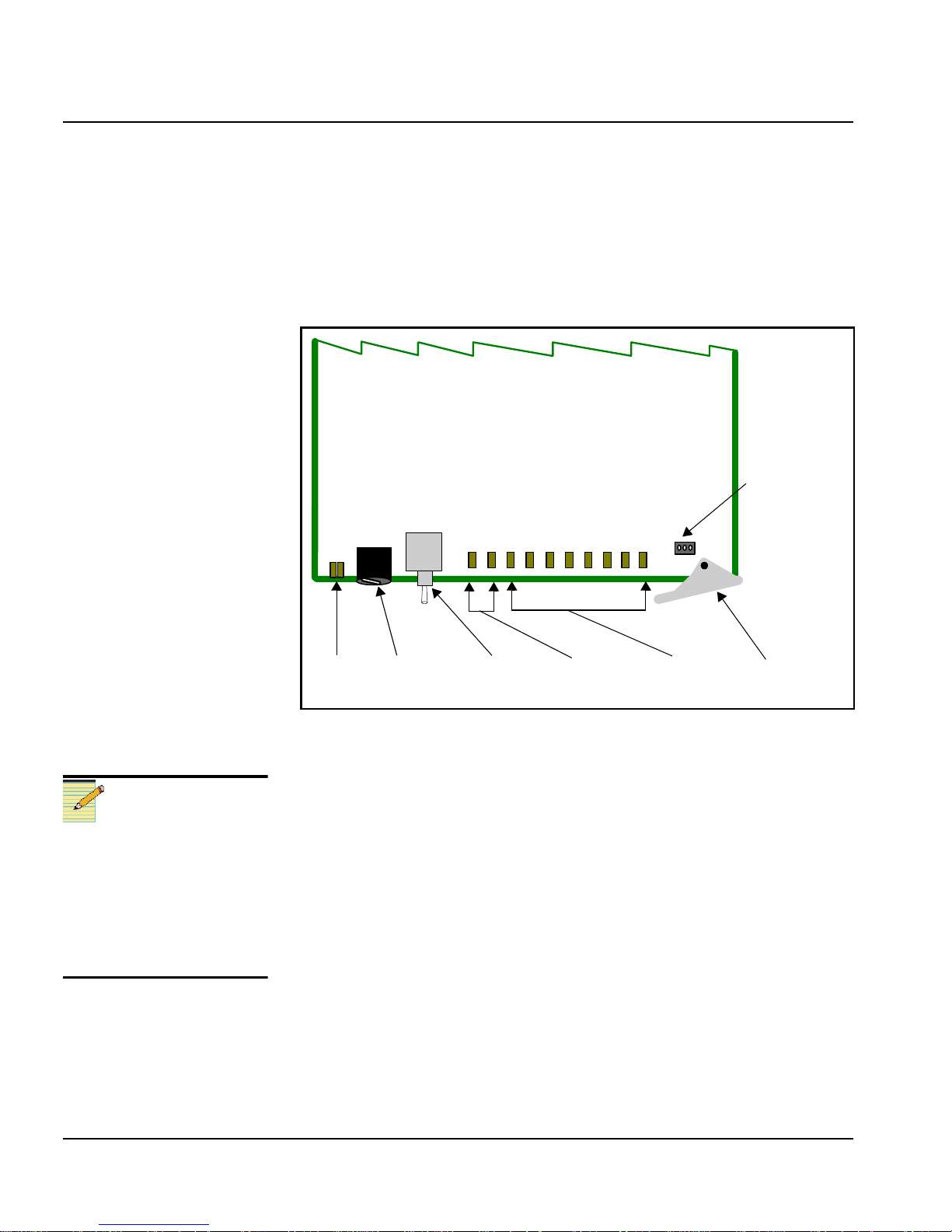
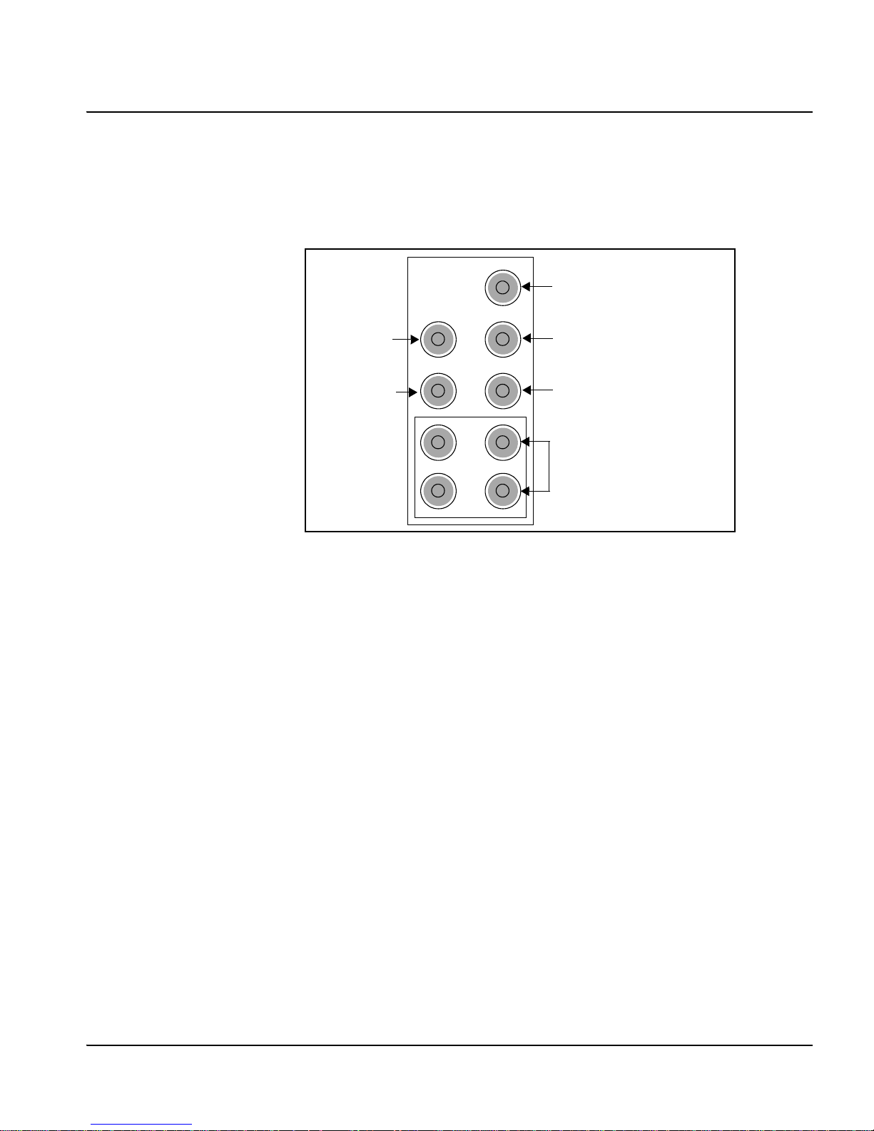
Front Module
Figure 1-1 is a generic top-front view of a typical 6800+ module and
shows the general location of standard LEDs, controls, and jumpers.
Remote/local
control
jumper
Note
Before connecting the
ENC6800+ connector to
primary power, check and, if
necessary, set the input
voltage selector switch on
the rear panel to match the
local line voltage.
Module
status
LEDs
Mode select
rotary
switch
Navigation
toggle
switch
Control
LEDs
Monitoring
LEDs
Extractor
handle
Figure 1-1. Typical 6800+ Module
Table 1-1 on page 5 briefly describes generic 6800+ LEDs, switches,
and jumpers. See “Chapter 3: Operation” for more information on
specific ENC/ENS6800+ module controls, LEDs, and jumpers.
4 ENC/ENS6800+ Installation and Operation Manual
Page 19

Table 1-1. Generic 6800+ Module Features
Feature Description
Chapter 1: Introduction
Module status
LEDs
Mode select
rotary switch
Navigation
toggle switch
Control LEDs Various lighting combinations of these control LEDs
Monitoring
LEDs
Local/Remote
control jumper
Various color and lighting combinations of these LEDs
indicate the module state.
Chapter 3 for more information.
This switch selects between various control parameters.
This switch navigates up and down through the available
control parameters:
• Up: Decrease
• Down: Increase
(sometimes referred to as “Bank Select LEDs”) indicate
the currently selected bank.
Bank as Indicated by Control LEDs” for more
information.
Each 6800+ module has a number of LEDs assigned to
indicate varying states/functions.
LEDs” in Chapter 3 for a description of these LEDs.
• Local: Locks out external control panels and allows
card-edge control only; limits the functionality of
remote software applications to monitoring
See “Monitoring LEDs” in
See Table 3-1 “Selected
See “Monitoring
• Remote: Allows remote or local (card-edge)
configuration, operation, and monitoring of the
ENC/ENS6800+
ENC/ENS6800+ Installation and Operation Manual 5
Page 20
Chapter 1: Introduction
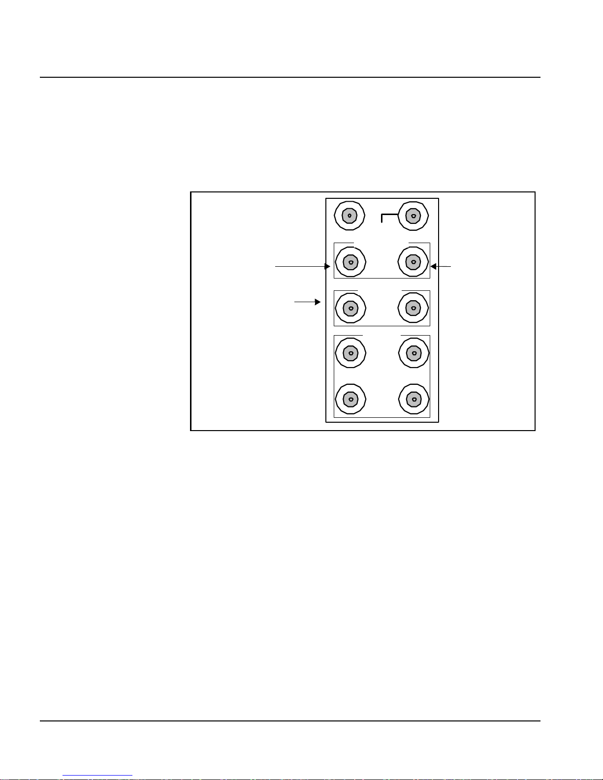
Back Connector
ENC/ENS6800+ Back Connector for FR6802+ Frame
Figure 1-2 shows the double-slot back connector used by the ENC/
ENS6800+ when installed in an FR6802+ frame.
SDI IN
GENLOCK
Genlock 1 Genlock 2
The RECLK SDI 1
can also serve as a
DATA I/O output. The
function assignment
is jumper selectable.
525 625
RECLK
SDI
12
CMPST
3
1
4
2
Figure 1-2. ENC/ENS6800+ Back Connector
6 ENC/ENS6800+ Installation and Operation Manual
Page 21
6800/7000 Series Frame Back Connector (Overlay)
Figure 1-3 shows the double-slot back connector overlay used by the
ENC/ENS6800+ when installed in a 6800/7000 series frame.
Chapter 1: Introduction
SDI IN
Genlock 525
(Genlock 1)
SDI RCLK or
IO_DELAY
Genlock 625
(Genlock 2)
SDI RLCK
COMPST VIDEO
(PAL- B/PAL-M/NTSC)
Figure 1-3. Back Connector Overlay for the 6800 Series Frame
ENC/ENS6800+ Installation and Operation Manual 7
Page 22
Chapter 1: Introduction
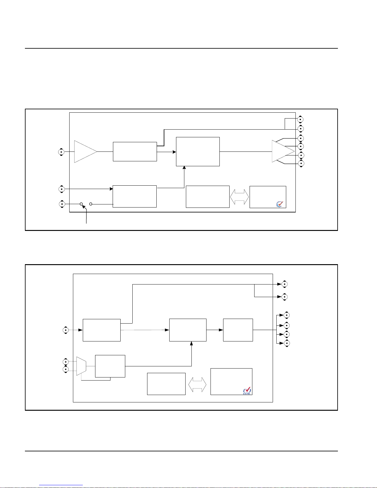
Signal Flow
Figure 1-4 shows the signal flow for the ENC6800+ module, and
Figure 1-5 shows the signal flow for the ENS6800+ module:
SDI
outputs
SDI input
NTSC reference
input
PAL reference
input
Frame reference
Equalizer and
deserializer
Genlock
Figure 1-4. ENC6800+ Signal Flow Diagram
Composite
encoder DAC
Front-edge
user interface
Composite
outputs
CCS control/
monitor port
SDI reclocked
output 1
SDI reclocked
output 2
SDI video
Input
Reference
video
input
Equalizer
and
deserializer
Genlock
Figure 1-5. ENS6800+ Signal Flow Diagram
8 ENC/ENS6800+ Installation and Operation Manual
Card-edge
control
Composite
encoder
DAC /
LPF
CCS control /
monitor port
Composite
video outputs
Page 23

Overview
Caution
Chapter 2
Installation
This chapter describes the ENC/ENS6800+ installation process,
including the following topics:
Before installing this product,
read the 6800+ Series Safety
Instructions and Standards
Manual shipped with every
FR6802+ Frame Installation
and Operation Manual or
downloadable from
www.broadcast.harris.com/
leitch. This safety manual
contains important information
about the safe installation and
operation of 6800+ series
products.
• “Maximum 6800+ Frame Power Ratings” on page 10
• “Unpacking the Module” on page 11
• “Setting Jumpers” on page 12
• “Installing 6800+ Modules” on page 15
• “Making Connections” on page 15
• “Removing 6800+ Modules” on page 15
See the FR6802+ Frame Installation and Operation Manual for
information about installing and operating an FR6802+ frame and its
components.
See the 6800/7000 Series Frames and Power Supply Installation and
Operation Manual for information about installing and operating a
6800/7000 series frame.
ENC/ENS6800+ Installation and Operation Manual 9
Page 24

Chapter 2: Installation
Maximum 6800+ Frame Power Ratings
The power consumption for the ENC6800+ module is 6.7 W and for the
ENS6800+ is 7.5 W.
Table 2-1 and Table 2-2 describe the maximum allowable power
ratings for 6800+ frames. Note the given maximums before installing
any 6800+ modules in your frame.
Table 2-1. Maximum Power Ratings for 6800+ Frames When
Using an AC Power Supply
6800+ Frame
Type
FR6802+DM
(frame without fans)
FR6802+DMF
(frame with fans)
FR6802+X
(frame without fans)
FR6802+XF
(frame with fans)
Max. Frame
Power
Dissipation
50 W 10 5 W
120 W 10 12 W
50 W 20 2.5 W
120 W 20 6 W
Number
of Usable
Slots
Max. Power
Dissipation
Per Slot
Table 2-2. Maximum Power Ratings for 6800+ Frames When
Using a DC Power Supply
6800+ Frame
Type
FR6802+DM48
(frame without fans)
Max. Frame
Power
Dissipation
50 W 10 5.0 W
Number
of Usable
Slots
Max. Power
Dissipation
Per Slot
FR6802+DMF48
(frame with fans)
FR6802+X48
(frame without fans)
FR6802+XF48
(frame with fans)
10 ENC/ENS6800+ Installation and Operation Manual
105 W 10 10.5 W
50 W 20 2.5 W
105 W 20 5.25 W
Page 25

Unpacking the Module
Preparing the Product for Installation
Before you install the ENC/ENS6800+, perform the following:
• Check the equipment for any visible damage that may have
Note
occurred during transit.
Chapter 2: Installation
Contact your customer service
representative if parts are
missing or damaged.
• Confirm receipt of all items on the packing list. See “Checking the
Packing List” for more information.
• Remove the anti-static shipping pouch, if present, and all other
packaging material.
• Retain the original packaging materials for possible re-use.
See “Unpacking/Shipping Information” on page v for information
about returning a product for servicing.
Checking the Packing List
Table 2-3. Available Product Packages
Ordered Product Content Description
ENC/ENS6800+
ENC/ENS6800+D
• One ENC/ENS6800+ front module
• One ENC/ENS6800+ Installation and Operation
Manual
• One ENC/ENS6800+ front module
• One standard, double-slot, 10 BNC back
connector
ENC/ENS6800+ Installation and Operation Manual 11
• One ENC/ENS6800+ Installation and Operation
Manual
ENC/ENS6800+DR One standard, double-slot, 10 BNC back connector
153-00092-00
(Optional item)
ENC/ENS6800+ back connector overlay
(for use in 6800/7000 series frames)
Page 26

Chapter 2: Installation
Setting Jumpers
The ENC/ENS6800+ module has three jumpers that you need to set:
•J3 (See “Jumper J3 for Local or Remote Control” on page 12)
•J1 (See “Setting Jumper J1 for Genlock Source” on page 13)
• P1 (See “Setting Jumper P1 for Reclocking and IO_DELAY
Output” on page 14)
Figure 2-1. Location of the J3, J1 and P1Jumpers
Jumper J3 for Local or Remote Control
Follow this procedure to set the J3 jumper for either local or remote
Note
You need to configure modules
for local or remote operation
prior to power-up. To change
the configuration, first remove
power from the module, reset
the jumper, and then reapply
power.
The white triangle near the
jumper pins on the module
indicates pin 1.
control:
1. Locate jumper J3 on the module (beside the extractor handle).
Figure 2-1 shows the standard location of the J3 jumper.
12 ENC/ENS6800+ Installation and Operation Manual
Page 27

Chapter 2: Installation
2. Place a jumper on pins 1 and 2 to set the module for Remote
control or pins 2 and 3 to set the module for Local control. See
Figure 2-2.
3 2 1 3 2 1
Remote control setting
Local control setting
Figure 2-2. Jumper J3 Settings for Local and Remote Control
Setting Jumper J1 for Genlock Source
Follow this procedure to select the Genlock source by setting the
J1 jumper to either Local or Frame mode:
1. Locate jumper J1 on the module. See Figure 2-1 on page 12.
2. Place a jumper on pins 1 and 2 if the genlock source is from the
local back connector (“L”) or pins 2 and 3 if the genlock source is
from the frame (“F”). The frame genlock is available only with the
FR6802+ frame.
1 2 3
Local mode
1 2 3
Frame mode
ENC/ENS6800+ Installation and Operation Manual 13
Figure 2-3. Jumper J1 Settings for Local or Frame Mode
The genlock source is not only selected by the J1 jumper setting
described above, but by the Reference Input Select parameter setting
you make in Bank 0, rotary switch setting D (see Table 3-3: “Card-Edge
Parameter Options— ENC/ENS6800+ Modules” on page 22).
Parameter setting options include the following:
• Genlock 1 (labeled 525 on the rear module)/ Frame Genlock: If
this setting is chosen, then the genlock source must come from
either the Genlock 1 input of the rear module (labeled 525) or from
Page 28

Chapter 2: Installation
Note
Even though the rear module is
labeled 525 for Genlock 1 and
625 for Genlock 2 either type of
standard can be applied to either
of the inputs. They are not 525
or 625 dependent. However the
same type of genlock format
(NTSC or PAL-B) should never
be applied to both genlock input
sources at the same time.
the FR6802+ frame genlock input. This is determined by the
position of jumper J1 on the ENC6800+ or ENS6800+ module as
shown in Figure 2-3.
• Genlock 2 (labeled 625 on the rear module): If this setting is
chosen, the genlock source will be taken from the Genlock 2 input
of the rear module and is independent of the jumper J1 setting.
• Auto: Varies between Genlock 1/Frame and Genlock 2 genlock.
This is used if the card is expected to auto-switch between an NTSC
or PAL-M reference and a PAL-B reference based on the video
input. In this case one reference input would be applied to the
Genlock 2 input, and the other reference input would be applied to
either Genlock 1 or Frame. Then when the input signal changes
between SD 525 and SD 625, the genlock will automatically switch
to the appropriate genlock source. Remember that jumper J1
determines whether Genlock 1 or Frame is the source of the first
genlock input (see Figure 2-3).
When the genlock source input is valid, the Genlock LED will turn
green. If you are using an ENS6800+ and the Genlock LED never turns
green, ensure that the Frame Sync Mode parameter is not set to Delay.
Setting Jumper P1 for Reclocking and IO_DELAY Output
Follow this procedure to set the P1 jumper to select Reclocked SDI or
IO_DELAY output to a BNC output connector on the back module:
1. Locate jumper P1 on the module. See Figure 2-1 on page 12.
2. Place a jumper on pins 2 and 3 to set the module for SDI RCLK, or
Note
The ENC6800+ does not
have IO_DELAY.
place a jumper on pins 1 and 2 and another jumper on pins 3 and 4
to set the module to output IO_DELAY.
1
234
Reclocked SDI output IO_Delay output
1
234
Figure 2-4. Jumper P1 Settings for Reclocked SDI or
IO_Delay Output
14 ENC/ENS6800+ Installation and Operation Manual
Page 29

Installing 6800+ Modules
There are two types of modules:
Caution
Before installing your modules,
see the Maximum 6800+ Frame
Power Ratings chart at the
beginning of this chapter.
• Double-slot back connectors
• Front modules
Back connectors for this module come in the double-slot size. Up to ten
front modules can fit in an FR6802+ frame if they are connected to
double-slot back connectors (two spaces are required to accommodate
the extra width of the back connector).
You can install most 6800+ modules in any unused slot without
interfering with other frame functions.
Making Connections
Once you have installed the ENC/ENS6800+ module, you can connect
it to the appropriate input and outputs. See Figure 1-2 on page 6 and
Figure 1-3 on page 7.
Chapter 2: Installation
Removing 6800+ Modules
To remove a module from an FR6802+ or 6800/7000 series frame,
Note
Modules are hot-swappable and
can be removed or replaced
without powering down the
frame.
follow these steps:
1. Pull out the finger-release screws on the right and left side of the
front panel, and then open it.
2. Grasp the extractor handle on the installed module, and then pull
the module out of its slot using the handle as a lever.
3. Close the front panel to ensure proper frame ventilation.
4. Remove the back connector from an FR6800+ frame in this way:
a. Unscrew the top of the corresponding back connector, and tip it
towards you.
ENC/ENS6800+ Installation and Operation Manual 15
Page 30

Chapter 2: Installation
Caution
b. Pull the bottom lip of the back connector from its slot.
c. Reinstall a new or blank back connector in the empty slot to
ensure proper frame ventilation.
To prevent overheating during
general frame operation and
maintain proper airflow, keep
the front panel closed and all
back connector slots covered
during operation.
5. Remove the back connector overlay from the back panel of a
6800/7000 series frame. Replace with a new back connector
overlay, if required.
16 ENC/ENS6800+ Installation and Operation Manual
Page 31

Overview
Chapter 3
Operation
This chapter describes how to operate the ENC/ENS6800+ using
card-edge controls only. See the following documents for information
on how to operate this product remotely:
• +Pilot Lite User Manual for serial interface
• CCS Pilot, CoPilot, Navigator, or RCP-CCS-1U Remote Control
Panel manual for Ethernet interface
The following topics are discussed in this chapter:
• “Operating Notes” on page 18
• “LEDs and Alarms” on page 30
• “Changing Parameter Settings” on page 20
• “Setting ENC/ENS6800+ Control Parameters” on page 22
• “LEDs and Alarms” on page 30
ENC/ENS6800+ Installation and Operation Manual 17
Page 32

Chapter 3: Operation
Operating Notes
When setting the control parameters on the ENC/ENS6800+, observe
the following:
• If you make changes to certain parameters, other related parameters
• When you change a parameter, the effect is immediate. However,
may also be affected. See “Cross-Functional Parameter Changes”
on page 19 for more information.
the module requires up to 20 seconds to save the latest change.
After 20 seconds, the new settings are saved and will be restored if
the module loses power and must be restarted.
18 ENC/ENS6800+ Installation and Operation Manual
Page 33

Chapter 3: Operation
Cross-Functional Parameter Changes
When you configure certain parameters, you force a change in other
associated parameters. The following table lists the secondary changes
that occur when you make these parameter selections.
Table 3-1. Cross-Functional Parameter Changes
Parameter Option Affected Parameter Change
SDI Video Standard 525 H Phase (ENS6800+ only) Range is 0-63.518 µs
V Phase (ENS6800+ only) Range is 0-524 Ln
Black Level Enabled
Setup Enabled
Setup Starting Line Enabled
VBI Lines 6, 7, 8, 9, 22, and 23Disabled
625 H Phase (ENS6800+ only) Range is 0-63.963 µs
V Phase (ENS6800+ only) Range is 0-624 Ln
Black Level Disabled
Setup Disabled
Setup Starting Line Disabled
VBI Lines 6, 7, 8, 9, 22, and 23Enabled
Frame Sync Mode (ENS6800+
only)
XCR Block (ENS6800+ only) Remove XCR Enable, XCR Filter Disabled
VBI Field Field 1 VBI Filter (All Lines) Affects Field 1
Delay Fine Phase Disabled
Sync Fine Phase Enabled
Insert XCR Enable, XCR Filter Enabled
Field 2 VBI Filter (All Lines) Affects Field 2
ENC/ENS6800+ Installation and Operation Manual 19
Page 34

Chapter 3: Operation
Changing Parameter Settings
Follow these steps to change the ENC/ENS6800+ parameter settings:
1. Rotate the mode select rotary switch (hex switch) to “0.”
2. Once the hex switch is set to “0,” toggle the navigation switch up or
down to select a bank.
View the two control LEDs next to the navigation toggle switch to
see which bank is currently selected.
See Table 3-2 “Parameter Options” to view the various banks, hex
switch positions, and corresponding parameter options and values.
Table 3-2. Selected Bank as Indicated by Control LEDs
LED D2 LED D1 Bank Number
Off Off 0
Note
For best results, use the
available 6800+ software
control options (serial/local or
Ethernet/remote) to aid in
viewing, setting, and confirming
parameter values.
Off On 1
On Off 2
On On 3
3. Rotate the hex switch to the parameter number (1 to 9) or letter
(A to F) of the option you want to set.
4. Toggle the navigation switch to select and set the value of the
chosen parameter.
5. Rotate the hex switch to another parameter number/letter in the
current bank, and then repeat step 4.
or
Rotate the hex switch to “0” again to select a different bank, and
then repeat steps 3 and 4.
20 ENC/ENS6800+ Installation and Operation Manual
Page 35

Recalling Default Parameter Settings
Table 3-2 “Parameter Options” describes all of the parameter settings
for the ENC/ENS6800+, including the original factory defaults. To
return this module to its default settings, you can either reset each
parameter individually or do a global recall following this procedure:
1. Rotate the hex switch to “0.”
2. Toggle the navigation switch to the bank number “0.”
Use the control LEDs to verify which bank you have selected, or
use an available 6800+ software control option (serial/local or
Ethernet/remote) to aid in confirming your bank selection.
3. Rotate the hex switch to the global recall parameter “F.”
4. Toggle the navigation switch to “On.”
Use an available 6800+ software control option to aid in viewing,
setting, and confirming the parameter value.
Chapter 3: Operation
Reading Software and Hardware Versions
The current software version of your ENC/ENS6800+ module can only
be viewed using a CCS-enabled control panel or a CCS software
application, such as Pilot or +Pilot Lite. See your RCP-CCS-1U
Installation and Operation Manual, CCS software application user
manual, or CCS software application online help for information on
viewing software and hardware version numbers.
ENC/ENS6800+ Installation and Operation Manual 21
Page 36

Chapter 3: Operation
Setting ENC/ENS6800+ Control Parameters
The following table lists all of the available parameters and options for
Note
the ENC/ENS6800+. All parameters clip unless otherwise indicated.
The sequence of options
listed in the Options column
mirrors the sequence
achieved when you move the
Navigation Toggle switch
up.
The On/Off combinations of the control LEDs on the card-edge indicate
the active bank number. See “Changing Parameter Settings” on page 20
for more information.
Legend
Bold option=Indicates that this is the default setting for the parameter
[RO]=Indicates that parameters are read-only/feedback, and cannot be
Note
Bank 1 parameter options
are available for selection on
ENS6800+ modules only.
used to select controls
All parameters clip unless otherwise noted.
Table 3-3. Card-Edge Parameter Options— ENC/ENS6800+ Modules
Bank,
Rotary
Parameter Name Function Parameter Option
Switch
0, 0 Bank Select Selects a bank
• Bank 0
• Bank 1
• Bank 2
• Bank 3
(These parameters wrap)
0, 1 SDI Video Standard Selects the video standard input
0, 2 For Future Use
0, 3 Black Level Adjusts the picture brightness ±7.5 IRE
0, 4 Luma Gain Adjust the luminous intensity of the
video signal
0, 5 Chroma Gain Adjusts the picture color saturation ±3.0 dB
22 ENC/ENS6800+ Installation and Operation Manual
•625
•525
•Auto
(0 IRE)
±3.0 dB
(0 dB)
(0 dB)
Page 37

Chapter 3: Operation
Table 3-3. Card-Edge Parameter Options— ENC/ENS6800+ Modules(Continued)
Bank,
Rotary
Parameter Name Function Parameter Option
Switch
0, 6 Chroma Phase Adjust the chroma phase with respect to
burst
0, 7 Video Output Standard
Set
0, 8 Active Video Setup Controls the addition of the SETUP (7.5
0, 9 Setup Starting Line Selects the start of the active video line
Sets the video standard for the
Composite output
IRE) pedestal signal to the active video
lines in 525 line standard for the analog
video output
where the SETUP (7.5 IRE) pedestal is
being applied in 525 line standard for
the analog video output
±180°
(0°)
•NTSC
(525 LED is
green)
(525: NTSC)
•PAL-M
(525 LED is
orange)
•PAL-B
(625: PAL-B)
•Off
•On
10-22 Ln
(22 Ln)
0, A For Future Use
0, B Fine Phase (ENS6800+
only)
0, C SCH Offset Controls the SCH offset for the
0, D Reference Input Select Selects the reference input source
ENC/ENS6800+ Installation and Operation Manual 23
Adjusts the output timing in fine
increments
composite video output to properly
construct the color framing sequence
This parameter works in conjunction
with the J1 Local/Frame jumper setting.
See “Setting Jumper J1 for Genlock
Source” on page 13 for more
information.
±45°
(0°)
• PAL-M/B: 0°, 90°,
180°, 270°
•NTSC:
0°, 180°
(0°)
•Genlock 2
(625 on overlay)
•Genlock
1/Frame
(525 on overlay)
•Auto
Page 38

Chapter 3: Operation
Table 3-3. Card-Edge Parameter Options— ENC/ENS6800+ Modules(Continued)
Bank,
Rotary
Parameter Name Function Parameter Option
Switch
0, E Genlock Mode Selects the Genlock mode
0, F Factory Recall Recalls the factory settings
Note: Bank 1 parameter options are available for selection on ENS6800+.
1, 0 Bank Select Selects a bank
1, 1 Vertical Phase
(ENS6800+ only)
Adjusts the vertical timing
• Free Run
• Mono Lock
•Burst
•Auto
• Bank 0
• Bank 1
• Bank 2
• Bank 3
(These parameters wrap)
• 0 to 524 Ln
D1-525
• 0 to 624 Ln
D1-625
(0 ln)
(These parameters wrap)
1, 2 Horizontal Phase
(ENS6800+ only)
1, 3 - 4 For Future Use
1, 5 Frame Sync Mode
(ENS6800+ only)
1, 6 Freeze Type
(ENS6800+ only)
1, 7 Freeze Enable
(ENS6800+ only)
24 ENC/ENS6800+ Installation and Operation Manual
Adjusts the horizontal timing
Selects the operational mode for the
Frame Synchronizer
Selects the output video mode when the
input video is disrupted
Forces the output video to freeze
• 0 to 63.518µs D1-525
• 0 to 63.963µs D1-625
0 µs
(These parameters wrap)
• Delay Mode
• Sync Mode
•Field 1
•Field 2
• Frame
• Disabled
•Enabled
Page 39

Chapter 3: Operation
Table 3-3. Card-Edge Parameter Options— ENC/ENS6800+ Modules(Continued)
Bank,
Rotary
Parameter Name Function Parameter Option
Switch
1, 8 Loss of Video Output
(ENS6800+ only)
1, 9 Test Signal Select
(ENS6800+ only)
1, A Test Signal Enable
(ENS6800+ only)
1, B For Future Use
1, C XCR Function Block
(ENS6800+ only)
1, D XCR Function Enable
(ENS6800+ only)
1, E XCR Filter Select
(ENS6800+ only)
Selects the output video mode when the
input video is disrupted
Selects the type of internal test signal
Controls the activation of the internal
test signal generator
Controls the insertion of the cross-color
reduction circuit in the signal
processing path (not applicable to
PAL-B)
Controls the activation of cross-color
reduction (not applicable to PAL-B)
Selects the type of cross-color reduction
(not applicable to PAL-B)
•Pass
• Black
• Freeze
•Color Bars
• Mod Ramp
• MultiBurst
•Pulse & Bars
•Off
•On
• Remove
• Insert
• Disabled
•Enabled
• Filter 1
• Filter 2
• Filter 3
1, F For future Use
Table 3-4. Card Edge Parameter Options—Groups 2 and 3 (D1-525)
Bank,
Rotary
Parameter Name Function Parameter Option
Switch
2, 0 Bank Select Selects a bank
2, 1 Field Select Selects a field for parameters in groups
2 and 3
ENC/ENS6800+ Installation and Operation Manual 25
• Bank 0
• Bank 1
• Bank 2
• Bank 3
(These parameters wrap)
• Field 1
•Field 2
Page 40

Chapter 3: Operation
Table 3-3. Card-Edge Parameter Options— ENC/ENS6800+ Modules(Continued)
Bank,
Rotary
Parameter Name Function Parameter Option
Switch
2, 2 Line 10 VBI Selects the processing mode for this
VBI line
2, 3 Line 11 VBI Selects the processing mode for this
VBI line
2, 4 Line 12 VBI Selects the processing mode for this
VBI line
2, 5 Line 13 VBI Selects the processing mode for this
VBI line
2, 6 Line 14 VBI Selects the processing mode for this
VBI line
2, 7 Line 15 VBI Selects the processing mode for this
VBI line
• Pass
• Luma only
•Blank
• Pass
• Luma only
•Blank
• Pass
• Luma only
•Blank
• Pass
• Luma only
•Blank
• Pass
• Luma only
•Blank
• Pass
• Luma only
•Blank
2, 8 Line 16 VBI Selects the processing mode for this
VBI line
2, 9 Line 17 VBI Selects the processing mode for this
VBI line
2, A Line 18 VBI Selects the processing mode for this
VBI line
2, B Line 19 VBI Selects the processing mode for this
VBI line
26 ENC/ENS6800+ Installation and Operation Manual
• Pass
• Luma only
•Blank
• Pass
• Luma only
•Blank
• Pass
• Luma only
•Blank
• Pass
• Luma only
•Blank
Page 41

Chapter 3: Operation
Table 3-3. Card-Edge Parameter Options— ENC/ENS6800+ Modules(Continued)
Bank,
Rotary
Parameter Name Function Parameter Option
Switch
2, C Line 20 VBI Selects the processing mode for this
VBI line
2, D Line 21 VBI Selects the processing mode for this
VBI line
2, E-F For Future Use
3, 0 Bank Select Selects a bank
3, 1-F For Future Use
Table 3-5. Card-Edge Parameter Options—Groups 2 and 3 (D1-625)
2, 0 Bank Select Selects a bank
• Pass
• Luma only
•Blank
• Pass
• Luma only
•Blank
• Bank 0
• Bank 1
• Bank 2
• Bank 3
(These parameters wrap)
• Bank 0
• Bank 1
• Bank 2
• Bank 3
(These parameters wrap)
2, 1 Field Select Selects a field for parameters in groups
2 and 3
2, 2 Line 6 VBI Selects the processing mode for this
VBI line
2, 3 Line 7 VBI Selects the processing mode for this
VBI line
2, 4 Line 8 VBI Selects the processing mode for this
VBI line
ENC/ENS6800+ Installation and Operation Manual 27
• Field 1
•Field 2
• Pass
• Luma only
•Blank
• Pass
• Luma only
•Blank
• Pass
• Luma only
•Blank
Page 42

Chapter 3: Operation
Table 3-3. Card-Edge Parameter Options— ENC/ENS6800+ Modules(Continued)
Bank,
Rotary
Parameter Name Function Parameter Option
Switch
2, 5 Line 9 VBI Selects the processing mode for this
VBI line
2, 6 Line 10 VBI Selects the processing mode for this
VBI line
2, 7 Line 11 VBI Selects the processing mode for this
VBI line
2, 8 Line 12 VBI Selects the processing mode for this
VBI line
2, 9 Line 13 VBI Selects the processing mode for this
VBI line
2, A Line 14 VBI Selects the processing mode for this
VBI line
• Pass
• Luma only
•Blank
• Pass
• Luma only
•Blank
• Pass
• Luma only
•Blank
• Pass
• Luma only
•Blank
• Pass
• Luma only
•Blank
• Pass
• Luma only
•Blank
2, B Line 15 VBI Selects the processing mode for this
VBI line
2, C Line 16 VBI Selects the processing mode for this
VBI line
2, D Line 17 VBI Selects the processing mode for this
VBI line
2, E Line 18 VBI Selects the processing mode for this
VBI line
28 ENC/ENS6800+ Installation and Operation Manual
• Pass
• Luma only
•Blank
• Pass
• Luma Oonly
•Blank
• Pass
• Luma only
•Blank
• Pass
• Luma only
•Blank
Page 43

Chapter 3: Operation
Table 3-3. Card-Edge Parameter Options— ENC/ENS6800+ Modules(Continued)
Bank,
Rotary
Parameter Name Function Parameter Option
Switch
2, F For Future Use
3, 0 Bank Select Selects a bank
3, 1 Line 19 VBI Selects the processing mode for this
VBI line
3, 2 Line 20 VBI Selects the processing mode for this
VBI line
3, 3 Line 21 VBI Selects the processing mode for this
VBI line
3, 4 Line 22 VBI Selects the processing mode for this
VBI line
• Bank 0
• Bank 1
• Bank 2
• Bank 3
(These parameters wrap)
• Pass
• Luma only
•Blank
• Pass
• Luma only
•Blank
• Pass
• Luma only
•Blank
• Pass
• Luma only
•Blank
3, 5 Line 23 VBI Selects the processing mode for this
For Future Use
ENC/ENS6800+ Installation and Operation Manual 29
VBI line
• Pass
• Luma only
•Blank
Page 44

Chapter 3: Operation
LEDs and Alarms
Monitoring LEDs
The ENC6800+ has five monitoring LEDs and ENS6800+ has seven
monitoring LEDs that serve as a quick monitoring reference. Figure 3-1
shows the general location of the monitoring LEDs on a generic 6800+
module. Table 3-6 describes each LED in more detail.
Figure 3-1. Location of ENC/ENS6800+ LEDs
30 ENC/ENS6800+ Installation and Operation Manual
Page 45

Chapter 3: Operation
Table 3-6. Monitoring LEDs
LED Color Indications Meaning
525 Off Selected input standard is
not D1-525
Flashing Green Selected input standard is
NTSC; valid D1-525 video
is not detected
Green Selected input standard is
NTSC; valid D1-525 video
is present
Flashing Orange Selected output standard is
PAL-M; valid D1-525 video
is not detected
Orange Selected output standard is
PAL-M; valid D1-525 video
is present
Auto Off Auto detection of the SDI
input standard is not active
Green Auto detection of the SDI
input standard is active
625 Off Selected input standard is
not D1-625
Flashing Green Selected output standard is
PAL-B; valid D1-625 video
is not present
Green Selected output standard is
PAL-B; valid D1-625 video
is present
EDH Off EDH is not present
Green EDH is present
ENC/ENS6800+ Installation and Operation Manual 31
Page 46

Chapter 3: Operation
Table 3-6. Monitoring LEDs (Continued)
LED Color Indications Meaning
Genlock Off Either the Genlock Mode
parameter is set to Free Run
or the Frame Sync Mode
parameter is set to Delay
Mode
Flashing Green Frame Sync Mode is set to
Sync Mode and Genlock
Mode is not set to Free
Run, but the module’s
output is not locked to
reference video
Green The module’s output is
locked to reference video
Freeze
(ENS6800+ only)
TSG
(ENS6800+ only)
Module Status LEDs
The ENC/ENS6800+ modules do not have any card-edge alarms.
Instead, module status LEDs on the corner of the module light up if an
error is detected. See Figure 3-1 for the location of these LEDs, and
Table 3-7 for a definition of the LED colors.
Off The module’s output is not
frozen
Green The module’s output is
frozen
Off The module’s test signal
generator is not active
Green The module’s test signal
generator is active
32 ENC/ENS6800+ Installation and Operation Manual
Page 47

Note
If the LED is flashing red,
please contact your customer
service representative.
Chapter 3: Operation
Alarms are usually logged and monitored within available software
control applications (for example, +Pilot Lite or Pilot). See the
appropriate software control user manual or online help for more
information.
Table 3-7. Module Status LED Descriptions
LED Color Sequence Meaning
Off There is no power to the module; the module
is not operational.
Green There is power to the module; the module is
operating properly.
Red There is an alarm condition.
Flashing red The module has detected a hardware/
firmware fault.
Alarms
Amber The module is undergoing configuration.
Table 3-8 describes the specific alarms for the ENC/ENS6800+. You
can only identify specific alarms using a software control application.
Table 3-8. Alarm Definitions
Alarm Name Alarm Description
Loss of SDI Indicates SDI video input is missing Major
Loss of
Reference_Locked
Indicates that Frame Sync Mode is
set to Sync Mode and Genlock mode
is not set to Free Run, but the
module’s output is not locked to
reference video
Alarm
Level
Major
ENC/ENS6800+ Installation and Operation Manual 33
Page 48

Chapter 3: Operation
34 ENC/ENS6800+ Installation and Operation Manual
Page 49

Overview
Chapter 4
Specifications
The following specification tables appear in this chapter:
• “Video Input” on page 36
• “Video Output” on page 37
• “Power Consumption” on page 38
Specifications and designs are subject to change without notice.
ENC/ENS6800+ Installation and Operation Manual 35
Page 50

Chapter 4: Specifications
Video Input
Serial Digital Video
Table 4-1. Serial Digital Video Input
Item Specifications
Standard SMPTE 259M-C, 270 Mbps, 525/625 component
Connector BNC per IEC 169-8
Impedance 75Ω
Return loss >18 dB to clock frequency
Signal level 800 mV ±10%
CMR voltage 30 V p-p, up to 60 Hz
Equalization Automatic up to: >23 dB, 259M-C (typical)
Reference Input
Table 4-2. Reference Video Input
Item Specifications
Level 1 V pk-to-pk
Signal type Analog composite NTSC/PAL-B
Connector BNC
Impedance 75Ω
Return loss >40 dB (typical) to 6 MHz
36 ENC/ENS6800+ Installation and Operation Manual
Page 51

Video Output
Composite Analog
Chapter 4: Specifications
Table 4-3. Composite Analog Video Output
Item Specifications
Standards NTSC, PAL-B, PAL-M
Impedance 75Ω
Return loss >40 dB to 5.75 MHz
Quantizing 12 bits
Frequency response ±0.15 dB to 5.5 MHz
Differential gain <1% (typically <0.5%)
Differential phase <1° (typically <0.5°)
DC offset ±50 mV
Chroma/luma delay <1.5 ns
Chroma/luma gain ±1.5%
Transient response <0.5% K factor
Line time distribution 0.1%
Signal to noise >60 dB rms with bandwidth 10 kHz to full
Adjustable vertical
blanking
• 10 to 21 lines for NTSC for both fields
(Field 2: 272 to 283)
• 6 to 23 lines for PAL for both fields
(Field 2: 318 to 335)
ENC/ENS6800+ Installation and Operation Manual 37
Page 52

Chapter 4: Specifications
Serial Digital Video
Table 4-4. Serial Digital Video Output
Data I/O Output
Item Specifications
Standard SMPTE 259M-C, 270 Mbps, 525/625 component
Connector BNC per IEC 169-8
Impedance 75Ω
Return loss >18 dB to clock frequency
Signal level 800 mV ±10%
DC offset 0 V ±0.5 V
Rise and fall times 0.75 ns to 1.5 ns
Table 4-5. Data I/O Output
Item Specification
Output ports 1
Connector BNC per IEC 169-8
Impedance 75Ω
Power Consumption
Table 4-6. Power Consumption
Module Power Consumption
ENC6800+ 6.7 W
ENS6800+ 7.5 W
38 ENC/ENS6800+ Installation and Operation Manual
Page 53

Operating Temperature
The operating temperature for ENC/ENS6800+ modules is 41° to
113°F (5° to 45°C).
Chapter 4: Specifications
ENC/ENS6800+ Installation and Operation Manual 39
Page 54

Chapter 4: Specifications
40 ENC/ENS6800+ Installation and Operation Manual
Page 55

)
Composite Encoder Filter
Appendix A
Filters
NTSC/PAL-M Pass Filter
Luminance
This filter is an “all pass” filter. No digital filtering is done on the
composite encoder. It is up to the user to supply a suitable signal that
corresponds to the user’s encoder application. This is very important
when the signal is being fed to a bandwidth-limited channel.
Chrominance
These filters are designed to the original RS-170A “I” specifications.
Filter specifications:
• <2 dB down at 1.3 MHz
• >20 dB down after 3 MHz
0
-5
-10
Level (dB)
-15
-20
-25
-30
00.511.5 22.53
Freq (MHz
ENC/ENS6800+ Installation and Operation Manual 41
Figure A-1. NTSC/PAL-M Studio Cr/Cb Filter
Page 56

Appendix A: Filters
PAL-B Pass Filter
Luminance
Chrominance
0
-5
This filter is an “all pass” filter. No digital filtering is done on the
composite encoder. It is up to the user to supply a suitable signal that
corresponds to the user’s encoder application. This is important when
the signal is being fed to a bandwidth-limited channel.
Filter specifications (same as Tx filter):
• <3 dB down before 1.3 MHz
• >20 dB down after 4 MHz
Level (dB)
-10
-15
-20
0 0.5 1 1.5 2 2.5 3
Fr e q ( M Hz)
Figure A-2. PAL-B Studio Cr/Cb Filter
42 ENC/ENS6800+ Installation and Operation Manual
Page 57

Cross-Color Reduction Filter
This section describes the cross-color reduction filters that are available
for the ENS-6804 board. The filter responses and characteristics are
limited to the structure of the custom FIR filter ASIC. These are 12-bit
coefficients with 15-tap folded FIR.
Filter Summary
The implementation of each Cross-Color Reduction filter consists of two
filters: a vertical high pass filter and a horizontal high pass filter. The
frequency response of the vertical HPF is fixed and is
non-programmable, while the horizontal HPF is programmable.
Table A-1 summarizes the selectable horizontal high pass filters. The
values are the approximate bandwidths for the application. Examine the
filter plots for greater detail.
Appendix A: Filters
Table A-1. Bandwidth of Cross-Color Reduction Filters
Horizontal Pass Filters Cutoff Frequency
Filter 1 6.0 MHz
Filter 2 5.8 MHz
Filter 3 5.0 MHz
ENC/ENS6800+ Installation and Operation Manual 43
Page 58

Appendix A: Filters
Vertical High Pass Filter Frequency Response
Figure A-3. XCR Vertical High Pass Filter Frequency Response
Horizontal High Pass Filters
Filter 1
Figure A-4. XCR Filter 1 High Pass Filter Frequency Response
44 ENC/ENS6800+ Installation and Operation Manual
Page 59

Filter 2
Appendix A: Filters
Filter 3
Figure A-5. XCR Filter 2 High Pass Filter Frequency Response
ENC/ENS6800+ Installation and Operation Manual 45
Figure A-6. XCR Filter 3 High Pass Filter Frequency Response
Page 60

Appendix A: Filters
46 ENC/ENS6800+ Installation and Operation Manual
Page 61

ENC/ENS6800+ Troubleshooting
Overview
Appendix B
The following checklists will help you solve some of the most
commonly seen issues.
It is split into the following two sections:
• “Genlock Issues” on page 48
• “Output Issues” on page 51
For best results, use + Pilot Lite software to check settings and
parameters if housed inside an FR6802+ frame. + Pilot Lite software is
installed on a PC that connects to the 6800+ frame via the serial port
connector at the rear of the frame, and can be downloaded from
www.broadcast.harris.com/leitch
connect between the PC and the 6800+ frame.
. Use a null modem RS-232 cable to
ENC/ENS6800+ Installation and Operation Manual 47
Page 62

Appendix B: ENC/ENS6800+ Troubleshooting
Genlock Issues
If the ENC/ENS6800+ cannot lock to genlock, proceed through the
following checklist:
1. Check that the Reference Input Select parameter is properly set.
Note
There are three choices:
Although the ENC6800+ does
not have a frame synchronizer,
it still uses the Genlock input for
correct color framing on the
composite outputs.
The ENC6800+ cannot be
upgraded to an ENS6800+ in
the field.
• Genlock 1/Frame Genlock - When this setting is chosen, the
genlock source must come from either the Genlock 1 input
(labelled 525) of the back module or from the FR6802+ frame
genlock input. This is determined by the position of jumper J1
on the ENC/ENS6800+ module.
Set to pins 1 and 2 for Genlock 1 input and pins 2 and 3 for
FRAME input, as shown below.
Figure B-1. Genlock Mode Jumper Locations and
Settings
Note
The back module has Genlock 1
labeled 525 and Genlock 2
labeled 625. Despite this
inaccurate labeling, Genlock 1
can accept an NTSC, PAL-M or
PAL-B reference and is not
limited to NTSC only as the
labeling implies. The same is
true for the Genlock 2 input.
48 ENC/ENS6800+ Installation and Operation Manual
• Genlock 2 - If this setting is chosen the genlock source will be
taken from the Genlock 2 input (labelled 625) of the back
module and is independent of the jumper‘ setting.
• Auto - If this setting is chosen, the genlock source will vary
between Genlock 1/Frame and Genlock 2 genlock. Use this
setting if the card is expected to auto-switch between an NTSC
or PAL-M reference and a PAL-B reference based on the video
input. In this case an NTSC reference would be applied one
Genlock input and a PAL-B reference applied to the other. Then
when the input signal changes between NTSC and PAL-B, the
genlock will automatically switch to the appropriate genlock
Page 63

Note
Appendix B: ENC/ENS6800+ Troubleshooting
source. Remember that the jumper determines whether
Genlock 1 or the Frame is the source of the second genlock
input (see Figure B-1 on page 48).
When the genlock input is valid, the D7 Genlock LED on the card
edge will turn green.
The same type of genlock
format (NTSC, PAL-M, or
PAL-B) should never be applied
to both genlock input sources at
the same time.
Note
Bent pins may also cause
communications issues with
Pilot Lite, Pilot or Navigator.
2. (ENS6800+ only) Check that the Frame Sync Mode parameter is
set to Sync mode. If this parameter is set to Delay, it will not
synchronize the video to the genlock reference.
3. Check that the Genlock Mode parameter is not set to Free Run
mode. If this parameter is set to Free Run, the video will not
synchronize to the genlock reference.
4. Check that the SDI Video Standard parameter is set to the correct
standard for the current video input. This parameter is normally left
in Auto mode where it will automatically switch between 525 and
625 SDI video standards as the input changes. However if this is
forced into 525 or 625, then the genlock input must match the
chosen standard. For example, if 625 mode is selected but an NTSC
reference is present on the genlock input, the unit will not genlock
or synchronize.
5. If the first four items are correct on your module, the next thing to
check is the back module. Follow these steps:
a. Unplug the front module.
b. Unscrew and remove the back module.
ENC/ENS6800+ Installation and Operation Manual 49
Page 64

Appendix B: ENC/ENS6800+ Troubleshooting
c. Check that the 20 pin spring connector at the bottom of the
back module does not have any bent or pressed in pins. (See
Figure B-2.) Even a slightly depressed or bent pin may cause
genlock issues.
20-pin connector
Figure B-2. Back Module to Front Module Connector
d. If there are bent pins carefully re-position them to their correct
positions.
If this is not possible then the back module can be exchanged
for a new one. Use part number ENC/ENS6800+DR.
6. If the ENC/ENS6800+ can still not be genlocked, attempt doing a
Factory Recall on the module.
50 ENC/ENS6800+ Installation and Operation Manual
Page 65

Output Issues
Appendix B: ENC/ENS6800+ Troubleshooting
If the SDI output has issues such as no output, unstable output or frozen
output, proceed with the following checklist.
1. Check that the Video Output Standard Set parameter is set
correctly. If a 525 SDI input is present, then the valid output
standard choices are NTSC or PAL -M. If PA L-B is c hos en b ut
NTSC is desired, the module will not pass good video.
2. (ENS6800+ only) - If the video output appears to be frozen, check
that the Freeze Enable parameter is not set to Enable. When this
parameter is set to Enable, the ENS6800+ will freeze the last video
frame or field that was received.
3. (ENS6800+ only) - If the video output appears to be stuck on a test
pattern, check that the Test Signal Enable parameter is not
enabled.
4. If Closed Captioning on Line 21 does not appear to be picked up by
CC decoders or is intermittent, ensure that the Line 21 VBI
parameters are set to Luma only. This bypasses any cross color
artifacts that may occur.
a. First go to the Field Select parameter and select Field 1.
b. Go to the Line 21 VBI parameter and select Luma only.
c. If there is Closed Caption 2 (CC 2) on Field 2 then go back to
the Field Select parameter and choose Field 2 and repeat step b.
If the CC decoder still has problems decoding the closed
captioning, check that there is no setup on Line 21. Go to the Setup
Starting Line parameter and set it to 22 so that setup is not added
to Line 21.
5. If the output is still not valid, try doing a Factory Recall.
6. Check the Module Status LED on the card edge. If it is flashing red,
there is a likely hardware or firmware fault. Contact Customer
Service.
If after going through this checklist the ENC6800+ or ENS6800+
module still does not operate as expected, contact customer service for
further assistance. Send an email to service@leitch.com
.
ENC/ENS6800+ Installation and Operation Manual 51
Page 66

Appendix B: ENC/ENS6800+ Troubleshooting
52 ENC/ENS6800+ Installation and Operation Manual
Page 67

Appendix C
Communication and Control
Troubleshooting Tips
Overview
Find the following troubleshooting information in this appendix:
• “General Troubleshooting Steps” on page 54
• “Software Communication and Control Issues” on page 55
• “Hardware Communication and Control Issues” on page 59
• “Contacting Customer Service” on page 59
ENC/ENS6800+ Installation and Operation Manual 53
Page 68

Appendix C: Communication and Control Troubleshooting Tips
General Troubleshooting Steps
Follow these steps in troubleshooting 6800+ product problems:
1. Review the “Software Communication and Control Issues” on
page 55 outlined in this chapter.
2. Search this product manual and other associated documentation for
Note
answers to your question.
Associated documentation for
6800+ series products can
generally be found in the
product-specific manual that
accompanies every module, in
the FR6802+ Frame
Installation and Operation
Manual, and in the 6800+
Safety Instructions and
Standards Manual.
Product documentation (including manuals, online help, application
notes, erratas, product release notes, and more) can be found on our
Web site at www.broadcast.harris.com/leitch
(Support section),
along with technical support information, training information,
product downloads, and the product knowledge base.
3. Contact your customer service representative if, after following
these initial steps, you cannot resolve the issue.
To contact customer service, see “Contacting Customer Service” on
page 59.
54 ENC/ENS6800+ Installation and Operation Manual
Page 69

Appendix C: Communication and Control Troubleshooting Tips
Software Communication and Control Issues
• “+ Pilot Lite Fails to Communicate with Installed Modules” on
page 55
• “+ Pilot Lite Does Not Find All Modules in Frame” on page 56
• “+ Pilot Lite or CCS Software Application Not Responding” on
page 57
• “+ Pilot Lite Cannot Control a Module Showing
in the Control Window” on page 57
• “+ Pilot Lite Status Bar Reports ‘Not Ready’” on page 57
• “CCS Software Application or Remote Control Panel Does Not
Communicate with Module” on page 58
• “Alarm Query Fails When a Device Reboots” on page 58
+
Pilot Lite Fails to Communicate with Installed Modules
Confirm that the following items are not the reason for the
communication failure:
• Proper module slot has not been specified (+ Pilot Lite is not
communicating with the appropriate slot). See your FR6802+
Frame Installation and Operation Manual for more information on
slot identification.
• COM port is used elsewhere (Check that the correct COM port is
configured in + Pilot Lite and that another application is not using
that COM port).
• Actual frame ID does not match with the two DIP switch settings in
the back of the frame (+ Pilot Lite is not communicating with the
proper frame). See your FR6802+ Frame Installation and
Operation Manual for more information on frame ID switch
settings.
• A null modem cable is not being used. Between the PC running
+ Pilot Lite and the FR6802+ frame, there should be a null RS-232
modem cable. At minimum, this requires that pins 2 and 3 are
crossed and 5 to 5 for ground.
ENC/ENS6800+ Installation and Operation Manual 55
• ICE6800+ module is installed in the frame (+ Pilot Lite control is
disabled if an ICE6800+ module is installed in the frame;
ICE6800+ modules are used for CCS control).
Page 70

Appendix C: Communication and Control Troubleshooting Tips
• A legacy 6800 series product is in the frame. + Pilot Lite cannot
communicate with legacy 6800 series products. They will not be
discovered or controlled by + Pilot Lite, although they can be
installed in the FR6802+ frame and work using card edge controls.
The module must be from the 6800+ product family.
• Check that the back module does not have any bent pinsFollow this
procedure:
a. Unplug the front module.
b. Unscrew and remove the back module.
c. View the 20-pin spring connector at the bottom of the back
module. See Figure C-1.
Figure C-1. Back Module to Front Module Connector
This connector should not have any bent or pressed pins. Even
a slightly depresssed or bent pin may cause genlock issues.
d. If there are bent pins, carefully re-position them to their correct
positions.
If this is not possible, then a back module can be exchanged for
a new one.
+
Pilot Lite Does Not Find All Modules in Frame
If a discovery is started too soon after frame power-up, + Pilot Lite will
not find all the installed modules. Refresh + Pilot Lite (File >
Refresh), and ensure that installed modules are fully powered-up
before discovery.
20-pin connector
56 ENC/ENS6800+ Installation and Operation Manual
Page 71

Appendix C: Communication and Control Troubleshooting Tips
If a module is plugged into the frame after a discovery, + Pilot Lite
does not automatically detect the module. Refresh + Pilot Lite (File >
Refresh) to discover the newly installed module.
If a Legacy 6800 series product is in the frame, + Pilot Lite will not
detect it. + Pilot Lite cannot communicate with legacy 6800 series
products. Although they can be installed in the FR6802+ frame and
work using card edge controls, they will not be discovered or controlled
by + Pilot Lite. For + Pilot Lite to find a module, it must be from the
6800+ product family.
+
Pilot Lite or CCS Software Application Not Responding
+ Pilot Lite and CCS applications such as Navigator or Pilot cannot run
on the same PC at the same time. Both applications can be installed, but
only one can be opened at a time.
+
Pilot Lite Cannot Control a Module Showing
in the Control Window
Consider these questions:
• Did you physically set the jumper for local control? If so, set this
jumper to the REM position for remote control.
• Is the module properly seated in the frame, and in the right slot?
Check the positioning of the module in its slot in the frame.
• Does the Control window indicate the device is “ready”? The
device may be powered off or disconnected from the network. See
“+ Pilot Lite Status Bar Reports ‘Not Ready’” on page 57.
+
Pilot Lite Status Bar Reports ‘Not Ready’
+ Pilot Lite reports each device’s connection status in the status bar. If
the connection status message reads “Not Ready,” check the following:
• Is the module properly seated in the frame? Check the position of
the module in the frame.
• Is the frame connected to the network? Check the device’s network
connection. For + Pilot Lite, an RS-232 null modem cable is
required between the PC and the FR6802+ frame.
ENC/ENS6800+ Installation and Operation Manual 57
If the status bar still reports no status or “Not Ready” for the frame or
device, try restarting + Pilot Lite.
Page 72

Appendix C: Communication and Control Troubleshooting Tips
CCS Software Application or Remote Control Panel Does
Not Communicate with Module
CCS software applications (such as Pilot, CoPilot, and Navigator) and
remote control panels require the purchase and installation of an
ICE6800+ module in an FR6802+XF frame in order to communicate
remotely via Ethernet.
Alarm Query Fails When a Device Reboots
When you reboot a device connected to your PC, the alarm traffic and
status update messages may cause an alarm query request to time out
and fail. While the query does not automatically retry, it will post an
“Alarm query failed” message to the Diagnostics window.
To clear an “Alarm query failed” message, right-click inside
the Diagnostics window, and then select Refresh from the resulting
context menu.
58 ENC/ENS6800+ Installation and Operation Manual
Page 73

Appendix C: Communication and Control Troubleshooting Tips
Hardware Communication and Control Issues
• “Frames Fail to Communicate with the PC after a Power Failure”
on page 59
• “Module Does Not Seem to Work” on page 59
Frames Fail to Communicate with the PC after a Power
Failure
Have you exited the software and restarted since the frame recovered
from its power failure? To restore communications between the PC and
the frames, ensure that the frames have three or more minutes to recover
from the power failure before you exit the application and restart the
PC.
Module Does Not Seem to Work
Although the following troubleshooting tips may seem obvious, please
take the time to ensure the following:
• All appropriate rear connections are securely made
• The board is securely installed (with no bent pins)
• The frame is turned on
Contacting Customer Service
We are committed to providing round-the-clock, 24-hour service to our
customers around the world. Visit our Web site at
www.broadcast.harris.com/leitch
customer service team in your geographical region.
for information on how to contact the
ENC/ENS6800+ Installation and Operation Manual 59
Page 74

Appendix C: Communication and Control Troubleshooting Tips
60 ENC/ENS6800+ Installation and Operation Manual
Page 75

Index
Symbols
Keywords
525 input 48
625 input 48
6800/7000 series frames 11
A
active bank number 22
active video setup 23
Adjustable vertical blanking 37
alarm query 58
alarms 30
analog composite 36
analog signal 2
application not responding 57
associated parameters 19
audio synchronizers, compatible 2
audio tracking signal 2
auto genlock select 48
available parameters 22
, 33, 58
B
back connector 6, 7, 11, 50
Bank Select 22
black 2
BNC connector 36
, 3, 22
C
chroma gain 22
chroma phase 23
Chroma/luma delay 37
Chroma/luma gain 37
chrominance 2
CJ1 jumper 12
clip 22
Closed Captioning 51
CMR voltage 36
color bars 3
compatibility 57
compatible audio synchronizers 2
composite analog signal 2
Composite Analog video output 37
Composite Encoder Filter 41
composite outputs 2
connections 15
Connector 36
contacting customer service 59
control LEDs 5
control problems 57
controls 4
Cr/Cb Filter 42
cross color artifacts 51
cross-color reduction 2
circuit 25
filter 43
cross-functional parameter changes 19
customer service, contacting 59
, 3, 41
, 38
, 20
card edge operation 17
CCS application 57
changing parameters 20
ENC/ENS6800+ Installation and Operation Manual 61
Page 76

Index
D
Data I/O Output 38
DC offset 37
default parameter settings 21
Delay Mode 32
description, product 2
Differential gain 37
Differential phase 37
digital filtering 42
digital internal processing, over-sample rate 2
discovery failure 56
disrupted video 25
, 38
E
EDH 31
EDH detection 2
Encoder Filter 41
encoding 2
Equalization 36
external genlock 2
, 3
F
Factory Recall 24, 51
fail to communicate 59
Field Select 51
filters 43
Fine Phase 19
FIR filter 43
FR6802+ frames 9
Frame Genlock 48
frame genlock 2
Frame Sync Mode 19
Free Run 32
freeze 3
Freeze Enable 51
Frequency response 37
front module 11
, 23
, 3
, 32, 49
, 24
G
Genlock 48
input 2
mode 24
source 13
, 3
, 32
H
H Phase 19
hardware version 21
horizontal high pass filter 43
Horizontal Phase 24
I
ICE6800+ 2
Impedance 36
input level 36
input signal loss 3
input signal type 36
input standard 31
installation 9
installed modules 56
internal processing 2
internal processing rate 2
internal test signal 25
IO_delay output 14
, 38
, 15
J
JA jumper 13
JB jumper 14
jitter 2
jumper CJ1 12
jumper JA 13
jumper JB 14
jumpers 4
, 3
, 12
, 44
62 ENC/ENS6800+ Installation and Operation Manual
Page 77

Index
L
LED locations 4
LEDs 30
Line 21 51
Line time distribution 37
local control 12
local mode 13
local/Remote control jumper 5
lock reference video 32
loss of input signal 3
Loss of Video Output 25
Luma Gain 22
Luma only 51
luminance 2
, 57
, 3, 41
M
making connections 15
Manual information vii
maximum allowable power ratings 10
mode select rotary switch 5
modulated ramp 3
module not found 56
module state 5
module status LEDs 5
modules, removing 15
monitoring LEDs 5
multiburst 3
–??, vii, ??–viii
, 32, 51
, 30
ports 38
standard 31
timing 23
video mode 25
outputs 2
over-sample rate 2
P
packing list 11
PAL-B Pass Filter 42
parameter
changes 19
settings 20
pass 3
Pass Filter 41
pedestal 2
Pilot Lite 2
pin spring connector 50
power
Precautions, safety xii
product description 2
Product servicing ix
pulse/bars 3
, 3
consumption 10
dissipation 10
failure 59
frame ratings 10
, 38
N
navigation toggle switch 5, 20
network connection 57
not ready status 57
NTSC/PAL-M pass filter 41
O
operating notes 18
operating temperature 39
operation 17
output
ENC/ENS6800+ Installation and Operation Manual 63
R
reboot device 58
recalling default parameter settings 21
reclocked outputs 2
reclocking SDI 14
reference 2
Reference Input Select 23
remote control 12
remote mode 13
removing modules 15
Return loss 36
Returning a product ix
, 3
, 48
, 57
, 38
Page 78

Index
Revision history of the manual vii
Rise and fall times 38
RoHS-compliance x
rotary switch 20
S
Safety precautions xii
SCH offset 2
SDI outputs 2
SDI video standard 19
serial digital video 36
output 38
setup 19
pedestal signal 23
starting line 19
Shipping and unpacking a product ix
Shipping information ix
signal flow 8
Signal level 36
Signal to noise 37
software version 21
Specifications 35
Standards
RoHS compliance x
video 36
WEEE compliance xi
status not ready 57
Support documents viii
sync mode 19
, 3, 23
, 22
, 23
, 38
Transient response 37
troubleshooting 47
Tx filter 42
types of modules 15
–59
U
Unpacking and shipping a product ix
Unpacking information ix
unpacking modules 11
usable slots 10
V
V Phase 19
VBI lines 19
vertical blanking 3
control 2
vertical high pass filter frequency response 44
video input 36
video output 37
standard set 23
Video Output Standard Set 51
video reference lock 32
video standard 36
W
Warranty information ii
WEEE compliance xi
Writing conventions viii
T
temperature 39
test signal 3
select 25
Test Signal Enable 51
Trademarks and copyrights ii
64 ENC/ENS6800+ Installation and Operation Manual
X
XCR Block 19
XCR filter 25
XCR function 25
, 45
Page 79

Page 80

Broadcast Communications Division
4393 Digital Way | Mason, OH USA 45040 | Tel: 1 (513) 459 3400
www.broadcast.harris.com
Copyright © 2006 Harris Corporation
Harris and Leitch are registered trademarks of Harris Corporation. Trademarks and tradenames are the property of their respective companies.
 Loading...