

Page 1

TECHNICAL MANUAL
888-2517-001
eCDi ™
Enhanced Transmitter
Network Interface
Enhanced Transmitter
Network Interface
T.M. No. 888-2517-001
© Copyright Harris Corporation 2003, 2004, 2005
All rights reserved
Rev H, January 3, 2005
Page 2

Returns And Exchanges
Damaged or undamaged equipment should not be returned unless written approval
and a Return Authorization is received from HARRIS Broadcast Communications
Division. Special shipping instructions and coding will be provided to assure proper
handling. Complete details regarding circumstances and reasons for return are to be
included in the request for return. Custom equipment or special order equipment is
not returnable. In those instances where return or exchange of equipment is at the
request of the customer, or convenience of the customer, a restocking fee will be
charged. All returns will be sent freight prepaid and properly insured by the
customer. When communicating with HARRIS Broadcast Communications
Division, specify the HARRIS Order Number or Invoice Number.
Unpacking
Carefully unpack the equipment and preform a visual inspection to determine that
no apparent damage was incurred during shipment. Retain the shipping materials
until it has been determined that all received equipment is not damaged. Locate and
retain all PACKING CHECK LISTs. Use the PACKING CHECK LIST to help
locate and identify any components or assemblies which are removed for shipping
and must be reinstalled. Also remove any shipping supports, straps, and packing
materials prior to initial turn on.
Technical Assistance
HARRIS Technical and Troubleshooting assistance is available from HARRIS
Field Service during normal business hours (8:00 AM - 5:00 PM Central Time).
Emergency service is available 24 hours a day. Telephone 217/222-8200 to contact
the Field Service Department or address correspondence to Field Service
Department, HARRIS Broadcast Communications Division, P.O. Box 4290,
Quincy, Illinois 62305-4290, USA. Technical Support by e-mail:
tsupport@harris.com. The HARRIS factory may also be contacted through a FAX
facility (217/221-7096).
Replaceable Parts Service
Replacement parts are available 24 hours a day, seven days a week from the
HARRIS Service Parts Department. Telephone 217/222-8200 to contact the service
parts department or address correspondence to Service Parts Department, HARRIS
CORPORATION, Broadcast Systems Division, P.O. Box 4290, Quincy, Illinois
62305-4290, USA. The HARRIS factory may also be contacted through a FAX
facility (217/221-7096).
NOTE:
The # symbol used in the parts list means used with (e.g. #C001 = used with C001).
ii 888-2517-001 1/3/05
WARNING: Disconnect primary power prior to servicing.
Page 3

Manual Revision History
eCDi ™ Technical Manual
REV. DATE ECN Pages Affected
Preliminary 02/17/2003 Created
Rev 0 08/14/2003 Manual Sent to Review
Rev A 9/22/2003 Manual Released
Rev B 10/31/2003 Added CD-1A note on page 2-4. Added page 2-21. Modified page
2-28 to reflect new features.
Rev C 11/13/2003 Added Sigma and Diamond Software requirements for connection
to eCDi, Pages 2-6 and 2-10.
Rev D 01/06/2004 Updated paragraph “2.4.5.3 Exciter Connections” for Platinum Z
FM and IBOC. Added Section 5, Interconnect Diagram. Changed
Appendix A to Section 6 and Appendix B to Section 7 (this caused
all Appendices to change designation, C becomes A etc). Added
Appendices D, E, F and G. Added note on page 2-16 referring to
Appendix G Platinum TV Monitor Board Upgrade.
Rev E 02/20/2004 Updated Sections 2, 3 and 4 to reflect the change in the
configuration port IP address and minor screen changes in software
revisions 2.6.K and higher. Specifically pages 2-22, 2-25, 2-26, 227, 3-10, 3-11 and 4-1.
Rev F 03/30/2004 M10248 Added CE markings and FCC notifications to Title Pages. Added
note to pages 2-1 and 2-24 concerning use of shielded cable.
Rev G 12/14/2004 50632 Updated Configuration information and screens in Section 2, pages
2-34 and 2-36 thru 2-39. Also updated Firewall port information in
Section 7. Minor corrections throughout the manual.
Rev H 01/03/2005 50767 Updated manual to include PowerCD (Display Unit/eCDi™).
Pages 1-2, 2-4, 2-21 and 7-4.
1/3/05 888-2517-001 MRH-1
WARNING: Disconnect primary power prior to servicing.
Page 4

MRH-2 888-2517-001 1/3/05
WARNING: Disconnect primary power prior to servicing.
Page 5
Guide to Using Harris Parts List Information
The Harris Replaceable Parts List Index portrays a tree structure with the major items being leftmost in the index. The
example below shows the Transmitter as the highest item in the tree structure. If you were to look at the bill of materials
table for the Transmitter you would find the Control Cabinet, the PA Cabinet, and the Output Cabinet. In the Replaceable
Parts List Index the Control Cabinet, PA Cabinet, and Output Cabinet show up one indentation level below the Transmitter
and implies that they are used in the Transmitter. The Controller Board is indented one level below the Control Cabinet so
it will show up in the bill of material for the Control Cabinet. The tree structure of this same index is shown to the right of
the table and shows indentation level versus tree structure level.
Example of Replaceable Parts List Index and equivalent tree structure:
Replaceable Parts List Index Part Number Page
Table 7-1. Transmitter 994 9283 001 7-2
Table 7-2. Control Cabinet 992 9244 002 7-3
Table 7-3. Controller Board 992 8344 002 7-6
Table 7-4. PA Cabinet 992 9400 002 7-7
Table 7-5. PA Amplifier 994 7894 002 7-9
Table 7-6. PA Amplifier Board 992 7904 002 7-10
Table 7-7. Output Cabinet 992 9450 001 7-12
The part number of the item is shown to the right of the description as is the page in the manual where the bill for that part
number starts. Inside the actual tables, four main headings are used:
Control Cabinet
992 9244 002
Controller Board
992 8344 002
Transmitter
994 9283 001
PA Cabinet
992 9400 002
PA Amplifier
992 7894 002
PA Amplifier Board
992 7904 002
Output Cabinet
992 9450 001
• Table #-#. ITEM NAME - HARRIS PART NUMBER - this line gives the information that corresponds to the
• Replaceable Parts List Index entry;
• HARRIS P/N column gives the ten digit Harris part number (usually in ascending order);
• DESCRIPTION column gives a 25 character or less description of the part number;
• REF. SYMBOLS/EXPLANATIONS column 1) gives the reference designators for the item (i.e., C001, R102,
etc.) that corresponds to the number found in the schematics (C001 in a bill of material is equivalent to C1 on the
schematic) or 2) gives added information or further explanation (i.e., “Used for 208V operation only,” or “Used
for HT 10LS only,” etc.).
Inside the individual tables some standard conventions are used:
• A # symbol in front of a component such as #C001 under the REF. SYMBOLS/EXPLANATIONS column
means that this item is used on or with C001 and is not the actual part number for C001.
• In the ten digit part numbers, if the last three numbers are 000, the item is a part that Harris has purchased and has
not manufactured or modified. If the last three numbers are other than 000, the item is either manufactured by
Harris or is purchased from a vendor and modified for use in the Harris product.
• The first three digits of the ten digit part number tell which family the part number belongs to - for example, all
electrolytic (can) capacitors will be in the same family (524 xxxx 000). If an electrolytic (can) capacitor is found
to have a 9xx xxxx xxx part number (a number outside of the normal family of numbers), it has probably been
modified in some manner at the Harris factory and will therefore show up farther down into the individual parts
list (because each table is normally sorted in ascending order). Most Harris made or modified assemblies will
have 9xx xxxx xxx numbers associated with them.
The term “SEE HIGHER LEVEL BILL” in the description column implies that the reference designated part number will
show up in a bill that is higher in the tree structure. This is often the case for components that may be
frequency determinant or voltage determinant and are called out in a higher level bill structure that is more
customer dependent than the bill at a lower level.
1/3/05 888-2517-001 v
WARNING: Disconnect primary power prior to servicing.
Page 6

vi 888-2517-001 1/3/05
WARNING: Disconnect primary power prior to servicing.
Page 7

!
WARNING:
THE CURRENTS AND VOLTAGES IN THIS EQUIPMENT ARE DANGEROUS. PERSONNEL MUST AT ALL TIMES OBSERVE SAFETY WARNINGS, INSTRUCTIONS AND REGULATIONS.
This manual is intended as a general guide for trained and qualified personnel who are aware of the
dangers inherent in handling potentially hazardous electrical/electronic circuits. It is not intended to
contain a complete statement of all safety precautions which should be observed by personnel in
using this or other electronic equipment.
The installation, operation, maintenance and service of this equipment involves risks both to
personnel and equipment, and must be performed only by qualified personnel exercising due care.
HARRIS CORPORATION shall not be responsible for injury or damage resulting from improper
procedures or from the use of improperly trained or inexperienced personnel performing such tasks.
During installation and operation of this equipment, local building codes and fire protection
standards must be observed.
The following National Fire Protection Association (NFPA) standards are recommended as reference:
- Automatic Fire Detectors, No. 72E
- Installation, Maintenance, and Use of Portable Fire Extinguishers, No. 10
- Halogenated Fire Extinguishing Agent Systems, No. 12A
!
WARNING:
ALWAYS DISCONNECT POWER BEFORE OPENING COVERS, DOORS, ENCLOSURES, GATES, PANELS OR SHIELDS. ALWAYS USE GROUNDING STICKS AND
SHORT OUT HIGH VOLTAGE POINTS BEFORE SERVICING. NEVER MAKE INTERNAL
ADJUSTMENTS, PERFORM MAINTENANCE OR SERVICE WHEN ALONE OR WHEN
FATIGUED.
Do not remove, short-circuit or tamper with interlock switches on access covers, doors, enclosures,
gates, panels or shields. Keep away from live circuits, know your equipment and don’t take chances.
!
WARNING:
IN CASE OF EMERGENCY ENSURE THAT POWER HAS BEEN DISCONNECTED.
!
WARNING:
IF OIL FILLED OR ELECTROLYTIC CAPACITORS ARE UTILIZED IN YOUR EQUIPMENT, AND IF A LEAK OR BULGE IS APPARENT ON THE CAPACITOR CASE WHEN
THE UNIT IS OPENED FOR SERVICE OR MAINTENANCE, ALLOW THE UNIT TO COOL
DOWN BEFORE ATTEMPTING TO REMOVE THE DEFECTIVE CAPACITOR. DO NOT
ATTEMPT TO SERVICE A DEFECTIVE CAPACITOR WHILE IT IS HOT DUE TO THE
POSSIBILITY OF A CASE RUPTURE AND SUBSEQUENT INJURY.
1/3/05 888-2517-001 vii
WARNING: Disconnect primary power prior to servicing.
Page 8

viii 888-2517-001 1/3/05
WARNING: Disconnect primary power prior to servicing.
Page 9

FIRST-AID
Personnel engaged in the installation, operation, maintenance or servicing of this equipment
are urged to become familiar with first-aid theory and practices. The following information is
not intended to be complete first-aid procedures, it is a brief and is only to be used as a
reference. It is the duty of all personnel using the equipment to be prepared to give adequate
Emergency First Aid and there by prevent avoidable loss of life.
Treatment of Electrical Burns
1. Extensive burned and broken skin
a. Cover area with clean sheet or cloth. (Cleanest available cloth
article.)
b. Do not break blisters, remove tissue, remove adhered particles of
clothing, or apply any salve or ointment.
c. Treat victim for shock as required.
d. Arrange transportation to a hospital as quickly as possible.
e. If arms or legs are affected keep them elevated.
NOTE:
If medical help will not be available within an hour and the victim is conscious and
not vomiting, give him a weak solution of salt and soda: 1 level teaspoonful of salt
and 1/2 level teaspoonful of baking soda to each quart of water (neither hot or
cold). Allow victim to sip slowly about 4 ounces (a half of glass) over a period of
15 minutes. Discontinue fluid if vomiting occurs. (Do not give alcohol.)
2. Less severe burns - (1st & 2nd degree)
a. Apply cool (not ice cold) compresses using the cleanest available
cloth article.
b. Do not break blisters, remove tissue, remove adhered particles of
clothing, or apply salve or ointment.
c. Apply clean dry dressing if necessary.
d. Treat victim for shock as required.
e. Arrange transportation to a hospital as quickly as possible.
f. If arms or legs are affected keep them elevated.
REFERENCE:
ILLINOIS HEART ASSOCIATION
AMERICAN RED CROSS STANDARD FIRST AID AND PERSONAL SAFETY
MANUAL (SECOND EDITION)
1/3/05 888-2517-001 ix
WARNING: Disconnect primary power prior to servicing.
Page 10

NOTE:
its are designed to provide reasonable protection against harmful interference
harmful interference to radio communications. Operation of this equipment in
a residential area is likely to cause harmful interference in which case the user
This device complies with part 15 of the FCC Rules. Operation is subject to
the following two conditions: (1) This device may not cause harmful interference, and (2) this device must accept any interference received, including
interference that may cause undesired operation.
NOTE:
NOTE: This equipment has been tested and found to comply with the limits
for a Class A digital device, pursuant to part 15 of the FCC Rules. These lim-
when the equipment is operated in a commercial environment. This equipment generates, uses, and can radiate radio frequency energy and, if not
installed and used in accordance with the instruction manual, may cause
will be required to correct the interference at his own expense.
x 888-2517-001 1/3/05
WARNING: Disconnect primary power prior to servicing.
Page 11

English
Finnish
Dutch
Bij deze verklaart HARRIS Broadcast Communications dat deze
French
Swedish
Danish
German
Greek
Italian
Spanish Por medio de la presente HARRIS Broadcast Communications
Portuguese
Hereby, HARRIS Broadcast Communications declares that this eCDi
Enhanced Transmitter Network Interface is in compliance with the
essential requirements and other relevant provisions of Directive
1999/5/EC.
HARRIS Broadcast Communications vakuuttaa täten että eCDi
Enhanced Transmitter Network Interface tyyppinen laite on direktiivin
1999/5/EY oleellisten vaatimusten ja sitä koskevien direktiivin muiden
ehtojen mukainen.
Hierbij verklaart HARRIS Broadcast Communications dat het toestel
eCDi Enhanced Transmitter Network Interface in overeenstemming
is met de essentiële eisen en de andere relevante bepalingen van
richtlijn 1999/5/EG
eCDi Enhanced Transmitter Network Interface voldoet aan de
essentiële eisen en aan de overige relevante bepalingen van Richtlijn
1999/5/EC.
Par la présente HARRIS Broadcast Communications déclare que
l'appareil eCDi Enhanced Transmitter Network Interface est
conforme aux exigences essentielles et aux autres dispositions
pertinentes de la directive 1999/5/CE
Par la présente, HARRIS Broadcast Communications déclare que ce
eCDi Enhanced Transmitter Network Interface est conforme aux
exigences essentielles et aux autres dispositions de la directive
999/5/CE qui lui sont applicables
Härmed intygar HARRIS Broadcast Communications att denna eCDi
Enhanced Transmitter Network Interface står I överensstämmelse
med de väsentliga egenskapskrav och övriga relevanta
bestämmelser som framgår av direktiv 1999/5/EG.
Undertegnede HARRIS Broadcast Communications erklærer herved,
at følgende udstyr eCDi Enhanced Transmitter Network Interface
overholder de væsentlige krav og øvrige relevante krav i direktiv
1999/5/EF
Hiermit erklärt HARRIS Broadcast Communications, dass sich
dieser/diese/dieses eCDi Enhanced Transmitter Network Interface in
Übereinstimmung mit den grundlegenden Anforderungen und den
anderen relevanten Vorschriften der Richtlinie 1999/5/EG befindet".
(BMWi)
Hiermit erklärt HARRIS Broadcast Communications die
Übereinstimmung des Gerätes eCDi Enhanced Transmitter Network
Interface mit den grundlegenden Anforderungen und den anderen
relevanten Festlegungen der Richtlinie 1999/5/EG. (Wien)
?? ??? ?????S? HARRIS Broadcast Communications ???O???
??? eCDi Enhanced Transmitter Network Interface
S?????FO????? ???S ??S ??S?O???S ??????S??S ??? ??S
?????S S??????S ????????S ??S ???G??S 1999/5/??
Con la presente HARRIS Broadcast Communications dichiara che
questo eCDi Enhanced Transmitter Network Interface è conforme ai
requisiti essenziali ed alle altre disposizioni pertinenti stabilite dalla
direttiva 1999/5/CE.
declara que el eCDi Enhanced Transmitter Network Interface
cumple con los requisitos esenciales y cualesquiera otras
disposiciones aplicables o exigibles de la Directiva 1999/5/CE
HARRIS Broadcast Communications declara que este eCDi
Enhanced Transmitter Network Interface stá conforme com os
requisitos essenciais e outras disposições da Directiva 1999/5/CE.
1/3/05 888-2517-001 xi
WARNING: Disconnect primary power prior to servicing.
Page 12
xii 888-2517-001 1/3/05
WARNING: Disconnect primary power prior to servicing.
Page 13

Table of Contents
Section 1
Introduction
Introduction. . . . . . . . . . . . . . . . . . . . . . . . . . . . . . 1-1
eCDi™ and the PowerCD™ Transmitter . . . . . . . 1-2
Hardware. . . . . . . . . . . . . . . . . . . . . . . . . . . . . . . . 1-3
Features . . . . . . . . . . . . . . . . . . . . . . . . . . . . . . . . . 1-4
eCDi™ Interfaces . . . . . . . . . . . . . . . . . . . . . . . . . 1-5
Web GUI (Graphical User Interface) . . . . . . . . . 1-5
SNMP Agent. . . . . . . . . . . . . . . . . . . . . . . . . . . . 1-6
Level 1 / Level 2 Functionality . . . . . . . . . . . . . . . 1-6
Security . . . . . . . . . . . . . . . . . . . . . . . . . . . . . . . . . 1-7
Remote Computer Requirements . . . . . . . . . . . . . 1-7
Section 2
Installation & Setup
Introduction. . . . . . . . . . . . . . . . . . . . . . . . . . . . . . 2-1
Hardware Installation . . . . . . . . . . . . . . . . . . . . . . 2-2
Connection Overview . . . . . . . . . . . . . . . . . . . . . . 2-3
Detailed Installation Procedures by Transmitter. . 2-4
SigmaCD Transmitter. . . . . . . . . . . . . . . . . . . . . 2-5
AC Power. . . . . . . . . . . . . . . . . . . . . . . . . . . . . 2-5
Transmitter Serial Connection. . . . . . . . . . . . . 2-5
Sigma Main Controller Setup . . . . . . . . . . . . . 2-6
Exciter Connections. . . . . . . . . . . . . . . . . . . . . 2-7
DiamondCD Series™ Transmitter . . . . . . . . . . . 2-9
AC Power. . . . . . . . . . . . . . . . . . . . . . . . . . . . . 2-9
Transmitter Serial Connection. . . . . . . . . . . . . 2-9
DiamondCD Main Controller Setup . . . . . . . 2-10
Exciter Connections. . . . . . . . . . . . . . . . . . . . 2-11
PlatinumCD and Platinum Analog TV Transmitters2-
13
Mounting and AC Power . . . . . . . . . . . . . . . . 2-13
Transmitter Serial Connection. . . . . . . . . . . . 2-13
Exciter Connections. . . . . . . . . . . . . . . . . . . . 2-14
Platinum TV Transmitter Settings . . . . . . . . . 2-16
Ranger Transmitter. . . . . . . . . . . . . . . . . . . . . . 2-17
Mounting and AC Power . . . . . . . . . . . . . . . . 2-17
Transmitter Serial Connection. . . . . . . . . . . . 2-17
Exciter Connections. . . . . . . . . . . . . . . . . . . . 2-17
Platinum Z FM and IBOC Transmitters. . . . . . 2-18
Mounting and AC Power . . . . . . . . . . . . . . . . 2-18
Transmitter Serial Connection. . . . . . . . . . . . 2-18
Exciter Connections. . . . . . . . . . . . . . . . . . . . 2-19
Atlas Transmitter . . . . . . . . . . . . . . . . . . . . . . . 2-20
Atlas Digital Mounting and AC Power . . . . . 2-20
Atlas Analog Mounting and AC Power. . . . . .2-20
Transmitter Serial Connection. . . . . . . . . . . . .2-20
Exciter Connections. . . . . . . . . . . . . . . . . . . . .2-20
PowerCD™ Digital UHF Transmitter . . . . . . . . .2-21
APEX Exciter Setup . . . . . . . . . . . . . . . . . . . . . . .2-22
Setting APEX IP Address . . . . . . . . . . . . . . . . .2-23
CD-1A Electronic Serial Number Reset. . . . . . . .2-24
Initial Turn-On . . . . . . . . . . . . . . . . . . . . . . . . . . .2-25
eCDi™ Configuration. . . . . . . . . . . . . . . . . . . . . .2-26
Troubleshooting Tips . . . . . . . . . . . . . . . . . . . . .2-28
Apply Changes. . . . . . . . . . . . . . . . . . . . . . . . . .2-41
Backing Up the Configuration . . . . . . . . . . . . . .2-42
Restoring a Configuration File. . . . . . . . . . . . . .2-42
Reset Computer IP Address . . . . . . . . . . . . . . . .2-42
Section 3
Operation
Introduction. . . . . . . . . . . . . . . . . . . . . . . . . . . . . . .3-1
Logging In. . . . . . . . . . . . . . . . . . . . . . . . . . . . . . . .3-2
Web Browser Interface . . . . . . . . . . . . . . . . . . . . . .3-3
Browser Menus. . . . . . . . . . . . . . . . . . . . . . . . . . . .3-4
Logs . . . . . . . . . . . . . . . . . . . . . . . . . . . . . . . . . . .3-5
Fault Log . . . . . . . . . . . . . . . . . . . . . . . . . . . . . .3-5
Meter Log . . . . . . . . . . . . . . . . . . . . . . . . . . . . .3-7
System Log . . . . . . . . . . . . . . . . . . . . . . . . . . .3-10
Web GUI Navigation . . . . . . . . . . . . . . . . . . . . . .3-12
Title Bar . . . . . . . . . . . . . . . . . . . . . . . . . . . . . . .3-13
Control Interface . . . . . . . . . . . . . . . . . . . . . . . .3-13
Fault Log / Help . . . . . . . . . . . . . . . . . . . . . . . . .3-14
Monitoring Interface . . . . . . . . . . . . . . . . . . . . .3-15
Monitoring Navigation . . . . . . . . . . . . . . . . . .3-15
GUI Navigation Summary . . . . . . . . . . . . . . . . .3-18
Performance Monitoring. . . . . . . . . . . . . . . . . . . .3-19
Performance Summary Screen. . . . . . . . . . . . . .3-19
Performance Faults Screen. . . . . . . . . . . . . . . . .3-20
Performance Meters Screen . . . . . . . . . . . . . . . .3-21
EVM / SNR . . . . . . . . . . . . . . . . . . . . . . . . . . .3-22
BenchMarks. . . . . . . . . . . . . . . . . . . . . . . . . . .3-22
View Functions . . . . . . . . . . . . . . . . . . . . . . . .3-24
Details Tab. . . . . . . . . . . . . . . . . . . . . . . . . . . .3-24
Performance Control Screen . . . . . . . . . . . . . . .3-25
CD-1A RTAC Control. . . . . . . . . . . . . . . . . . .3-25
APEX RTAC Control . . . . . . . . . . . . . . . . . . .3-26
xiii
Page 14

Table of Contents (continued)
Section 4
Software Updates
Introduction . . . . . . . . . . . . . . . . . . . . . . . . . . . . . . 4-1
Updating the eCDi™ . . . . . . . . . . . . . . . . . . . . . . . 4-2
Before Starting.... . . . . . . . . . . . . . . . . . . . . . . . . 4-2
Section 5
Interconnect Diagram
Introduction . . . . . . . . . . . . . . . . . . . . . . . . . . . . . . 5-1
Section 6
SNMP Connectivity
Introduction . . . . . . . . . . . . . . . . . . . . . . . . . . . . . . 6-1
SNMP Configuration. . . . . . . . . . . . . . . . . . . . . . . 6-1
Downloading the MIBs . . . . . . . . . . . . . . . . . . . . . 6-2
General MIB Description. . . . . . . . . . . . . . . . . . . . 6-3
MIB Functionality. . . . . . . . . . . . . . . . . . . . . . . . 6-4
Supported MIBs . . . . . . . . . . . . . . . . . . . . . . . . . 6-4
Shortcuts . . . . . . . . . . . . . . . . . . . . . . . . . . . . . . . 6-5
Section 7
Network Firewall Setup
Introduction . . . . . . . . . . . . . . . . . . . . . . . . . . . . . . 7-1
Firewall Ports. . . . . . . . . . . . . . . . . . . . . . . . . . . . . 7-1
Optional Port Settings . . . . . . . . . . . . . . . . . . . . . 7-2
PowerCD™ IP address and Port Settings . . . . . . 7-4
Appendix A
SigmaCD Fault and
Meter Log Reference
Introduction . . . . . . . . . . . . . . . . . . . . . . . . . . . . . .A-1
Fault Log Reference. . . . . . . . . . . . . . . . . . . . . . . .A-2
Meter Log Reference . . . . . . . . . . . . . . . . . . . . . . .A-8
Appendix B
DiamondCD Fault and
Meter Log Reference
Introduction . . . . . . . . . . . . . . . . . . . . . . . . . . . . . .B-1
Fault Log Reference. . . . . . . . . . . . . . . . . . . . . . . .B-2
Meter Log Reference . . . . . . . . . . . . . . . . . . . . . . .B-7
Appendix C
Atlas Fault and
Meter Log Reference
Introduction . . . . . . . . . . . . . . . . . . . . . . . . . . . . . . C-1
Fault Log Reference . . . . . . . . . . . . . . . . . . . . . . . C-2
Meter Log Reference. . . . . . . . . . . . . . . . . . . . . . . C-7
Appendix D
Ranger Fault and
Meter Log Reference
Introduction . . . . . . . . . . . . . . . . . . . . . . . . . . . . . . D-1
Fault Log Reference . . . . . . . . . . . . . . . . . . . . . . . D-2
Meter Log Reference. . . . . . . . . . . . . . . . . . . . . . .D-6
Appendix E
Platinum TV Fault and
Meter Log Reference
Introduction . . . . . . . . . . . . . . . . . . . . . . . . . . . . . . E-1
Fault Log Reference . . . . . . . . . . . . . . . . . . . . . . . E-2
Meter Log Reference. . . . . . . . . . . . . . . . . . . . . . . E-6
Appendix F
Platinum Z Fault and
Meter Log Reference
Introduction . . . . . . . . . . . . . . . . . . . . . . . . . . . . . . F-1
Fault Log Reference . . . . . . . . . . . . . . . . . . . . . . . F-2
Meter Log Reference. . . . . . . . . . . . . . . . . . . . . . . F-9
Appendix G
Platinum TV Monitor Board Upgrade
Introduction . . . . . . . . . . . . . . . . . . . . . . . . . . . . . . G-1
Upgrading Early Monitor Boards . . . . . . . . . . . . .G-2
Tools . . . . . . . . . . . . . . . . . . . . . . . . . . . . . . . . . . G-2
Required Installation Time . . . . . . . . . . . . . . . . . G-2
Installing Firmware and Memory . . . . . . . . . . . . G-3
Control Activation Jumpers . . . . . . . . . . . . . . . . G-5
Jumper Installation. . . . . . . . . . . . . . . . . . . . . . G-5
xiv
Page 15

eCDi ™
•
•
Ranger
Section 1
Introduction
Legal Notice
Before using the screens and programs associated with this product
you acknowledge that such are protected under the United States
and international copyright laws; the programs may be used only as
authorized under the terms of license from Harris Corporation and
its licensors, and that you are informed as to such license terms.
1.1 Introduction
eCDi™ is a Transmitter Network Interface appliance that provides a network
connection for control and monitoring of Harris transmitters that have a serial
connection port. Transmitters supported include:
Sigma CD
• Diamond CD
• Platinum CD
• Platinum (Analog)
!
WARNING:
ECDI™ IS A REMOTE CONTROL DEVICE. MAINTENANCE PERSONNEL SHOULD
TAKE ALL NECESSARY PRECAUTIONS TO DISABLE THE ECDI™ DURING TRANSMITTER MAINTENANCE. SPECIFICALLY, THE TRANSMITTER SHOULD BE PLACED
IN THE REMOTE DISABLE (LOCAL) MODE BEFORE SERVICING. ALWAYS DISCONNECT PRIMARY POWER BEFORE SERVICING EQUIPMENT.
• Platinum Z FM/IBOC
• Atlas Digital (DVB-T)
• Atlas Analog
1/3/05 888-2517-001 1-1
WARNING: Disconnect primary power prior to servicing.
Page 16
Section 1 Introduction
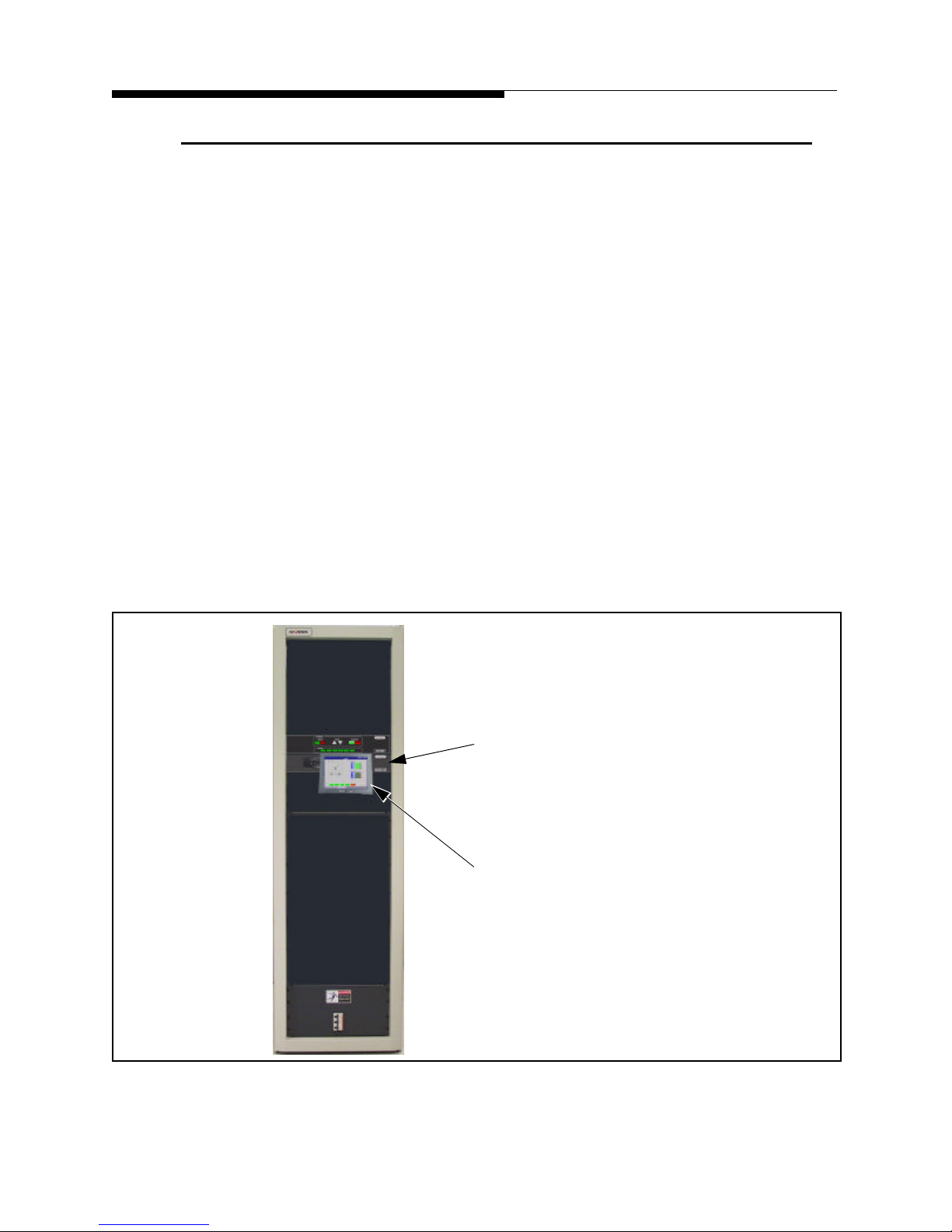
1.2 eCDi™ and the PowerCD™ Transmitter
For the Harris PowerCD Digital UHF Transmitter, the eCDi™ has been modified to
include a local GUI touchscreen interface in addition to its normal networking
capabilities. In the PowerCD transmitter the eCDi™ is the local transmitter control
interface using the attached 12" VGA touchscreen and has been renamed the "Display
Unit." This means that the eCDi™ provides both local and remote control for the
PowerCD transmitter.
The PowerCD transmitter will have a Display Unit (an eCDi™) in the Driver Cabinet
for system control and monitoring and one in each PA cabinet for individual cabinet
control and monitoring.
Information in this manual covers the basic setup and operation of the remote
networking side of the Display Unit (eCDi™). Operation of the Local GUI screens,
mounted on the front of the transmitter Display Units, is covered in the PowerCD
Transmitter Operators manual 888-2574-001.
eCDi ™
Also note that the PowerCD Display Unit (eCDi™) is a 2 rack unit high box (standard
eCDi™ is 1 rack unit) but uses the same software as all other eCDi™ units.
PowerCD
Driver
Cabinet
PowerCD Display Unit (modified eCDi™)
Local Transmitter touchscreen
display. Detailed operation of
these screens is covered in the
PowerCD Transmitter Operators
Manual 888-2574-001.
Figure 1-1 PowerCD™ Display Unit (modified eCDi™)
1-2 888-2517-001 1/3/05
WARNING: Disconnect primary power prior to servicing.
Page 17
eCDi ™
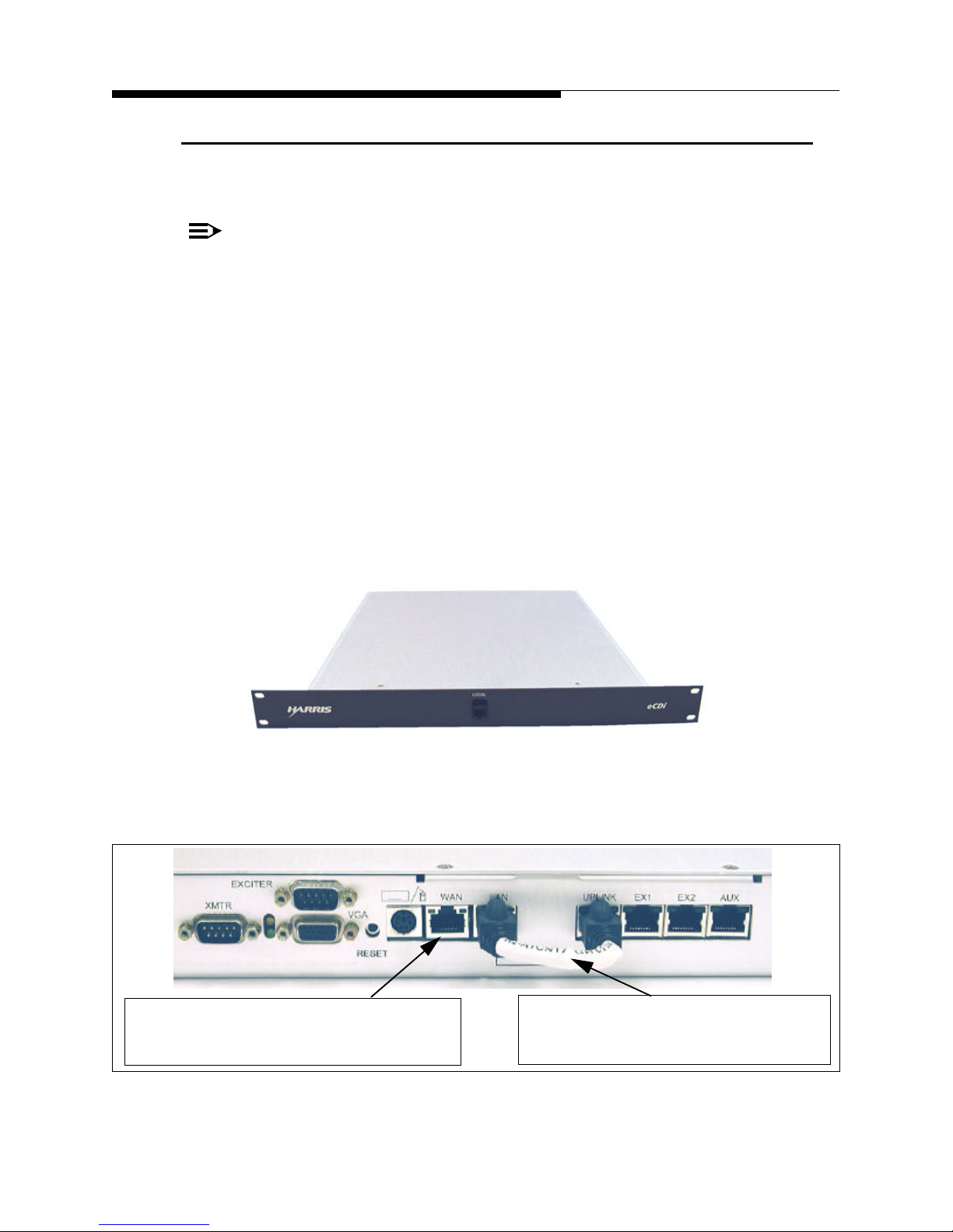
1.3 Hardware
• 1U device mounted in or near the transmitter control cabinet.
NOTE:
Due to the limitation of the length of the serial cables (50ft) that connect to the
transmitter, the eCDi™ hardware must be mounted within the reach of the maximum 50 ft. serial cables.
• Single Board Computer. Includes a 20GB hard drive, 4 port internal ethernet switch
and power supply.
• 1 ethernet port mounted on the front of the unit for configuration and utility monitor-
ing. Eliminates the need to access the rear of the unit after installation.
• 1 ethernet port mounted on the rear for connection to the station LAN or WAN.
• 3 ethernet ports mounted on the rear for permanent interconnect to transmitters and
exciters that have an ethernet interface (RJ-45).
• 2 serial ports mounted on the rear for connection to transmitters and exciters with a
serial interface.
Section 1 Introduction
Figure 1-2 eCDi™ Hardware Front Panel
This port connects to the Station LAN or
WAN or possibly a LAN modem if network
connection does not exist at the site.
1/3/05 888-2517-001 1-3
WARNING: Disconnect primary power prior to servicing.
Uplink jumper. This jumper should be
installed from the LAN connection to the
Figure 1-3 eCDi Connections
Page 18

Section 1 Introduction
1.4 Features
Web GUI Interface - The Web GUI interface allows access to transmitter control,
status and logging for any of the supported transmitters via a standard web browser
interface (Netscape or IE). The only other software required is a Java plugin and it is
downloaded from the eCDi™ the first time a computer accesses the unit.
Performance Monitoring - An optional software upgrade provides for performance
monitoring of DTV transmitters by networking an embedded version of the CD-EYE™
application.
Common Interface - The Web GUI creates a common display platform for all
transmitters. This allows immediate understanding of transmitter control and
monitoring regardless of the transmitter model.
Fault Logging - The fault log will hold up to 1000 events, is viewable on-line or can be
downloaded to Microsoft Excel or another common spreadsheet program.
eCDi ™
Meter Logging - Meter logging occurs periodically at a customer configured time
interval. The Meter log will hold up to 1000 events and can be downloaded to Microsoft
Excel or another common spreadsheet program.
Email Notification - faults and warnings are automatically sent to a customer
configured email address.
SNMP Agent - provides for connection to the Harris Broadcast Manager (HBM)or
RECON remote control system. It can also be connected, in a limited form, to other
non-Harris based SNMP Network Managers. For more information about SNMP
connectivity see " Section 6 SNMP Connectivity".
Remote Software Updates and Upgrades - eCDi™ uses In-System Programming
(ISP) that allows remote loading of software updates and upgrades. For more
information on ISP, see " Section 4 Software Updates".
1-4 888-2517-001 1/3/05
WARNING: Disconnect primary power prior to servicing.
Page 19
eCDi ™
1.5 eCDi™ Interfaces
eCDi™ allows access to transmitter control and monitoring via the following
interfaces:
• Web GUI
• SNMP Agent
• WAP (Wireless Access Protocol) via Cell Phone
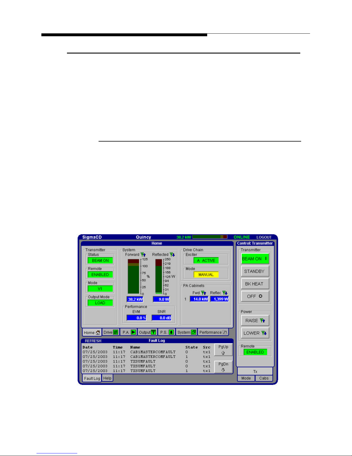
1.5.1 Web GUI (Graphical User Interface)
The Web GUI allows broadcasters to control and monitor their transmitter(s) through a
standard web browser (Netscape or IE) from anywhere network access is available.
This is the standard interface supplied with all eCDi™ units. An example of the Web
GUI main screen is shown in Figure 1-4. This main menu structure and layout is
basically the same for all transmitters, allowing operators to only have to learn one type
of interface for multiple types of transmitters. Actual readings and control buttons
available will be determined by the transmitter application. For more information on the
Web GUI see " Section 3 Operation".
Section 1 Introduction
Figure 1-4 Web GUI Interface Example
1/3/05 888-2517-001 1-5
WARNING: Disconnect primary power prior to servicing.
Page 20

Section 1 Introduction
1.5.2 SNMP Agent
The SNMP (Simple Network Management Protocol) Agent in eCDi™ provides
network connectivity using the Harris Broadcast Manager (HBM). HBM is a network
manager application that allows the centralized control and monitoring of multiple
transmitters and sites, but does not come with eCDi™. For more information on SNMP
control and the eCDi™, see " Appendix A SigmaCD Fault and Meter Log Reference".
NOTE:
The eCDi can also be accessed by other non-Harris SNMP Network Managers. In
this case, the MIB (Management Information Base) is a common MIB that is
used by nearly all Harris transmitters. A second “Extended” MIB exists and is
exclusively used by the Harris Broadcast Manager.
1.6 Level 1 / Level 2 Functionality
eCDi™ has 2 levels of software functionality that can be used with either the Web GUI
or the SNMP connection using the HBM Network Manager:
eCDi ™
a. Level 1 - Transmitter Remote Status Monitoring and Control. This allows
monitoring and control of virtually all transmitter parameters (limited to the
information that is available on the serial port of the transmitter). For most of the
listed transmitters, if it is available locally at the transmitter, it will be available
via the Web GUI. This level of functionality is included on all eCDi™ units.
b. Level 2 (optional upgrade) - Performance Monitoring and Control (only
available for DTV transmitters). This is an integrated form of the CD-EYE, 8VSB monitoring software and is an optional add-on to the base Level 1 software.
This allows performance monitoring of DTV transmitters with either CD-1A or
APEX exciters. Parameters to be monitored include:
1. Spectral Emissions - Equivalent to a spectrum analyzer plot of the system
output. Used to confirm compliance with FCC DTV emission mask.
2. EVM (Error Vector Magnitude) and SNR (Signal-to-Noise Ratio) mea-
surements and the Eye Diagram.
3. Constellation Diagram - This is an I (symbol) versus Q plot. Can be used to
show amplifier non-linearity.
4. RTAC (Real Time Adaptive Correction) Linear Correction - This plot
shows the gain and phase correction employed for linear distortions (Frequency response and Group delay) versus the frequency across the channel.
5. RTAC Non-Linear Correction (APEX exciter only) - This plot will display
the AM-AM and AM-PM correction employed for non-linear distortions in
the amplifier chain.
1-6 888-2517-001 1/3/05
WARNING: Disconnect primary power prior to servicing.
Page 21

eCDi ™
1.7 Security
eCDi™ provides password protection using 3 levels of security functionality:
1. Engineer - allows access to all functions
2. Operator - allows access to all status monitoring but limits transmitter
3. Monitor - allows access to all status monitoring with no control capability.
!
CAUTION:
OVERALL NETWORK SECURITY IS THE RESPONSIBILITY OF THE
CUSTOMER. INTEGRATION OF THE UNIT SHOULD BE BEHIND THE
CUSTOMERS FIREWALL WITH ACCESS THROUGH A VPN (VIRTUAL
PRIVATE NETWORK). SEE " SECTION 7 NETWORK FIREWALL SETUP" FOR
MORE INFORMATION.
Section 1 Introduction
control and configuration.
1.8 Downloading the Manual
The electronic version of this manual is available as a download from the eCDi™ Help
menu. See "3.4 Browser Menus" on page 3-4 for more information.
1/3/05 888-2517-001 1-7
WARNING: Disconnect primary power prior to servicing.
Page 22

Section 1 Introduction
1.9 Remote Computer Requirements
The following lists the minimum recommended requirements for a remote computer
that will be used to access the eCDi™ via the WEB Browser interface.
Hardware:
• Pentium III 400 MHz (Intel PIII+-compatible, 1GHz+ recommended)
• 128MB RAM (256MB or more recommended)
• 75MB of available hard drive space
• Mouse (mouse-wheel recommended)
• 28.8k modem (56k modem recommended or high speed TCP/IP network if
available)
• SVGA monitor running in at least 800x600 resolution
• SVGA Video card (hardware acceleration with Direct3D driver support
recommended)
eCDi ™
Operating System
• Windows 98 (1st edition) or newer
• Windows ME
• Windows 2000 with Service Pack 2 or newer
• Windows XP
Web Browser
• Internet Explorer 5.5 or higher with default security permissions
• Netscape 7.0 or higher
NOTE:
Microsoft DirectX 7.0 or later is highly recommended (comes pre-installed on
Windows 2000 and Windows XP).
1-8 888-2517-001 1/3/05
WARNING: Disconnect primary power prior to servicing.
Page 23

eCDi ™
Section 2
Installation &
Setup
2.1 Introduction
The information contained in this section is intended to explain the following:
• Hardware installation of the eCDi™ unit into a transmitter/control cabinet or
into a standard 19" rack.
• Connection of all required cables between the eCDi™ unit and the
transmitter and exciters and to the station LAN or WAN.
• Setup and configuration of the eCDi™ unit for connection to the station
LAN or WAN to provide Web GUI access.
!
CAUTION:
OVERALL NETWORK SECURITY IS THE RESPONSIBILITY OF THE CUSTOMER.
INTEGRATION OF THE UNIT SHOULD BE BEHIND THE CUSTOMERS FIREWALL
WITH ACCESS THROUGH A VPN (VIRTUAL PRIVATE NETWORK).
NOTE:
For SNMP connection to a network manager such as the Harris Broadcast
Manager, refer to " Section 6 SNMP Connectivity" after installing the eCDi™.
Use of the Web Browser interface is discussed in " Section 3 Operation".
IMPORTANT:
All ethernet cables connected to the eCDi™ should be shielded twisted pair
(STP) category 5 (Cat 5) cable. All cables supplied with the eCDi™ are shielded.
1/3/05 888-2517-001 2-1
WARNING: Disconnect primary power prior to servicing.
Page 24
Section 2 Installation & Setup
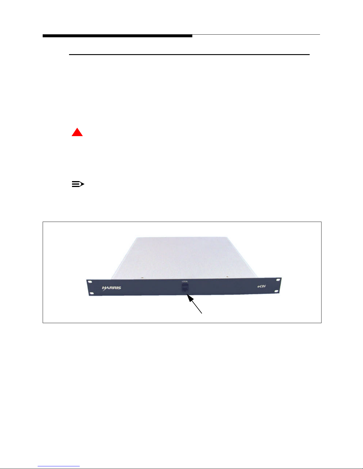
2.2 Hardware Installation
The eCDi™ fits in a standard 19" equipment rack or can be installed in a transmitter or
transmitter control cabinet if there is adequate room. Installation is a simple matter of
securing the front panel using 4 rack screws. Once eCDi™ is installed, the only port
that maintenance personnel will normally need access is the ethernet port on the front of
the unit for setup/configuration.
!
CAUTION:
DUE TO THE LIGHT WEIGHT OF THE UNIT AND THE LOCATION OF THE FANS,
NO REAR SUPPORT IS PROVIDED FOR RACK MOUNTING. THE ECDI™ SHOULD
NOT BE USED TO SUPPORT ANY WEIGHT OTHER THAN ITS OWN.
IMPORTANT:
If the eCDi™ is mounted outside the transmitter, it must be mounted within reach
of the maximum 50ft serial cables that connect to the transmitter and exciter(s).
eCDi ™
2-2 888-2517-001 1/3/05
WARNING: Disconnect primary power prior to servicing.
Configuration Port
Figure 2-1 eCDi™ Front Panel
Page 25
eCDi ™
2.3 Connection Overview
The following connections will need to be made to make the eCDi™ work:
NOTE:
Detailed information concerning the following connections is given in the
individual transmitter install procedures later in this section. See "2.4 Detailed
Installation Procedures by Transmitter" on page 2-4.
a. AC Power - eCDi™ is powered from a standard ac wall cord, 110/220Vac (auto-
switching). Do not turn the eCDi on at this time.
b. A short ethernet jumper cable is provided with the eCDi™. It connects the com-
puter LAN port to the Uplink port of the internal 5 port switch. It must be connected in the position shown in Figure 2-2. This is the hardware or transmitter
LAN side of the eCDi™.
NOTE:
For security reasons, the LAN port must never be connected to an outside
network. These are only to be used for connection to equipment or for local
configuration of the eCDi™ itself.
Section 2 Installation & Setup
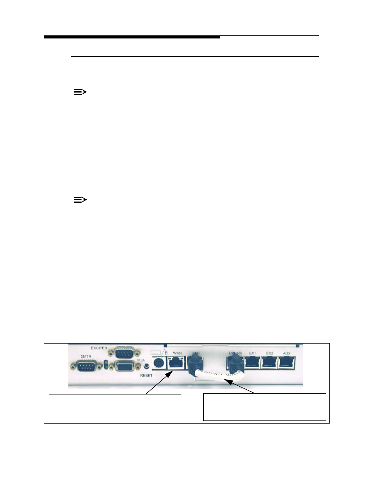
c. The leftmost Ethernet connection is the WAN connection. This should be con-
nected to the Station LAN or WAN or possibly a LAN modem if the only connection to the site is via dial-up phone line. For more information on setting IP
addresses for this port see "2.8 eCDi™ Configuration" on page 2-26.
d. XMTR (male D connector) connects to the transmitter controller serial port.
e. Exciter (male D connector) is for serial connection to CD-1A exciters in DTV
transmitters. To connect 2 exciters, this cable must have a “Y” adaptor installed.
f. The 2 Ethernet connections labeled EX1 and EX2 will be connected primarily to
exciters with ethernet ports, such as APEX™.
This port connects to the Station LAN or
WAN or possibly a LAN modem if network
connection does not exist at the site.
Uplink jumper. This jumper should be
installed from the LAN connection to the
Uplink port of the internal 5 port switch.
Figure 2-2 Rear Panel Connection Summary
1/3/05 888-2517-001 2-3
WARNING: Disconnect primary power prior to servicing.
Page 26

Section 2 Installation & Setup
2.4 Detailed Installation Procedures by Transmitter
For AC power, serial and Ethernet connections refer to the appropriate transmitter
procedure in the following paragraphs.
(If you are viewing this document in pdf format, then click on the desired link below)
"2.4.1 SigmaCD Transmitter" on page 2-5
"2.4.2 DiamondCD Series™ Transmitter" on page 2-9
"2.4.3 PlatinumCD and Platinum Analog TV Transmitters" on page 2-13
"2.4.4 Ranger Transmitter" on page 2-17
"2.4.5 Platinum Z FM and IBOC Transmitters" on page 2-18
"2.4.6 Atlas Transmitter" on page 2-20 (Analog or Digital)
eCDi ™
"2.4.7 PowerCD™ Digital UHF Transmitter" on page 2-21
IMPORTANT:
If the eCDi™ is to be connected to one or more APEX exciters, then also be sure
to see "2.5 APEX Exciter Setup" on page 2-22.
IMPORTANT:
If you are connecting the eCDi™ to a CD-1A, 8-VSB exciter, see "2.6 CD-1A
Electronic Serial Number Reset" on page 2-24.
2-4 888-2517-001 1/3/05
WARNING: Disconnect primary power prior to servicing.
Page 27

eCDi ™
TCP/IP port
(actually Com 3 from the
Section 2 Installation & Setup
2.4.1 SigmaCD Transmitter
2.4.1.1 AC Power
If the eCDi™ is installed in the SigmaCD control cabinet, then it can be plugged into
the already present UPS (Un-interruptible Power Supply) near the bottom front of the
cabinet. Be careful not to un-plug the local transmitter control GUI computer that is
plugged in here.
2.4.1.2 Transmitter Serial Connection
Connect the serial port labeled “XMTR” on the eCDi™ to J6 (Harris Protocol #1) or J7
(Harris Protocol #2) on the System I/O Board. A 50ft serial cable labeled “XMTR” is
provided in the cable kit.
System I/O Board
Rear View
Figure 2-3 SigmaCD Serial Connections on System I/O Board
Make sure the dipswitches, S4 or S5 (depending on the port being connected) on the
front side of the System I/O Board are set for a direct computer connection, as shown in
Figure 2-4. Only switches 3 and 4 should be ON (in the up position).
S3
S4
S5
J5
J6
J7
local GUI computer). Do not use this port
for eCDi™.
J6 and J7 also called HP1 and HP2 (Harris
Protocol). Either of these ports can be used
for connection to eCDi™. Both ports are
configurable for DTE (Tx and Rx swapped)
or DCE (Tx and Rx thru).
Do not change. Switches set for ISP to Cabinet Controller
ON
S3
1
4 5 678
2 3
Not used for eCDi™
ON
1
4 5 678
2 3
S4
ON
1
4 8
2 3
5 6
7
These settings assume a pin for pin cable
S5
J5 - TCP\IP
J6 - Harris Protocol #1
J7 - Harris Protocol #2
Figure 2-4 SigmaCD System I/O Board, Serial Port Switch Settings
1/3/05 888-2517-001 2-5
WARNING: Disconnect primary power prior to servicing.
Page 28

Section 2 Installation & Setup
2.4.1.3 Sigma Main Controller Setup
2.4.1.3.1 Sigma Software Requirements:
The SigmaCD transmitter has four (4) separate pieces of software/firmware which must
be at the following levels or higher before the eCDi™ can be connected:
• GUI Program Software for Windows® - GUI Version 5.0.0 (or higher)
• Main Controller Firmware - Version 3.0 (or higher)
• Amplifier Interface Board Firmware - Version 1.11 (or higher)
• IPA Module Firmware - Version 2.14 (or higher)
NOTE:
The most important one of the above is the Main Controller firmware but the
transmitter software/firmware is a package and all 4 should be updated to the
most current release levels at the same time. Failure to update all 4 to the levels
on the upgrade disk or CD could cause operational conflicts.
eCDi ™
To check the Firmware revision levels on the transmitter see the Introduction section
of the Sigma Software manual, 888-2469-001. Complete upgrade procedures are also
located in the software manual. Section 1 explains how to upgrade the GUI program,
while Section 3 explains how to do the ISP (In-System Programming) to update the
Main Controller, Amp Interface and IPA Module.
2.4.1.3.2 Main Controller Dipswitch Settings:
To deactivate the Main Controller password requirement (necessary for eCDi™
connection) set the S2 dipswitch on the transmitter Main Controller Board as follows:
• If eCDi™ is being connected to HP1 (J6), set S2-7 to ON
• If eCDi™ is being connected to HP2 (J7), set S2-8 to ON
NOTE:
If Remote GUI connection is not being used it is also recommended that the
Remote Access password in the Local GUI computer be set to Null (clear the
password and press enter). See the SigmaCD Software Manual for more
information.
2-6 888-2517-001 1/3/05
WARNING: Disconnect primary power prior to servicing.
Page 29

eCDi ™
Section 2 Installation & Setup
2.4.1.4 Exciter Connections
APEX Exciters
To connect the eCDi™ to an APEX™ exciter requires a standard ethernet cable (not
cross-over) with RJ-45 connectors on each end. Two (2) 50ft ethernet cables labeled
EX1 and EX2 have been provided. Connect the exciter(s) to the RJ-45 ports on the back
of the eCDi™ labeled EX1 and EX2 in Figure 2-2.
IMPORTANT:
The IP address and Subnet mask must also be set up in the APEX exciter. See
"2.5 APEX Exciter Setup" on page 2-22.
NOTE:
When routing the ethernet cable to the back of the exciter, make sure to follow the
cable supports and wiring harness to allow the exciters to be pulled completely
out the front to the extent of the rack slides. Cable ties have been provided to
secure the cables to prevent damage when the exciter is pulled out for service.
CD-1A Exciters
CD-1A exciters connect to the eCDi™ via serial port. Connect the provided 50ft serial
cable labeled “EXCITER” to the serial port labeled “EXCITER” on the eCDi™. Route
the cable into the back of the GUI control cabinet in the transmitter. This cable connects
to the provided Y adaptor in the transmitter control cabinet. The Y adaptor allows 2
exciters to be connected to the eCDi™ on the same serial port. Connection of the Y
adaptor cable depends on the age of the control cabinet. Both types of cabinet are
covered on the next page.
NOTE:
The exciters can both be connected to the same serial cable because they only have
access to the serial port if they are the active or ON-AIR exciter in the transmitter.
1/3/05 888-2517-001 2-7
WARNING: Disconnect primary power prior to servicing.
Page 30
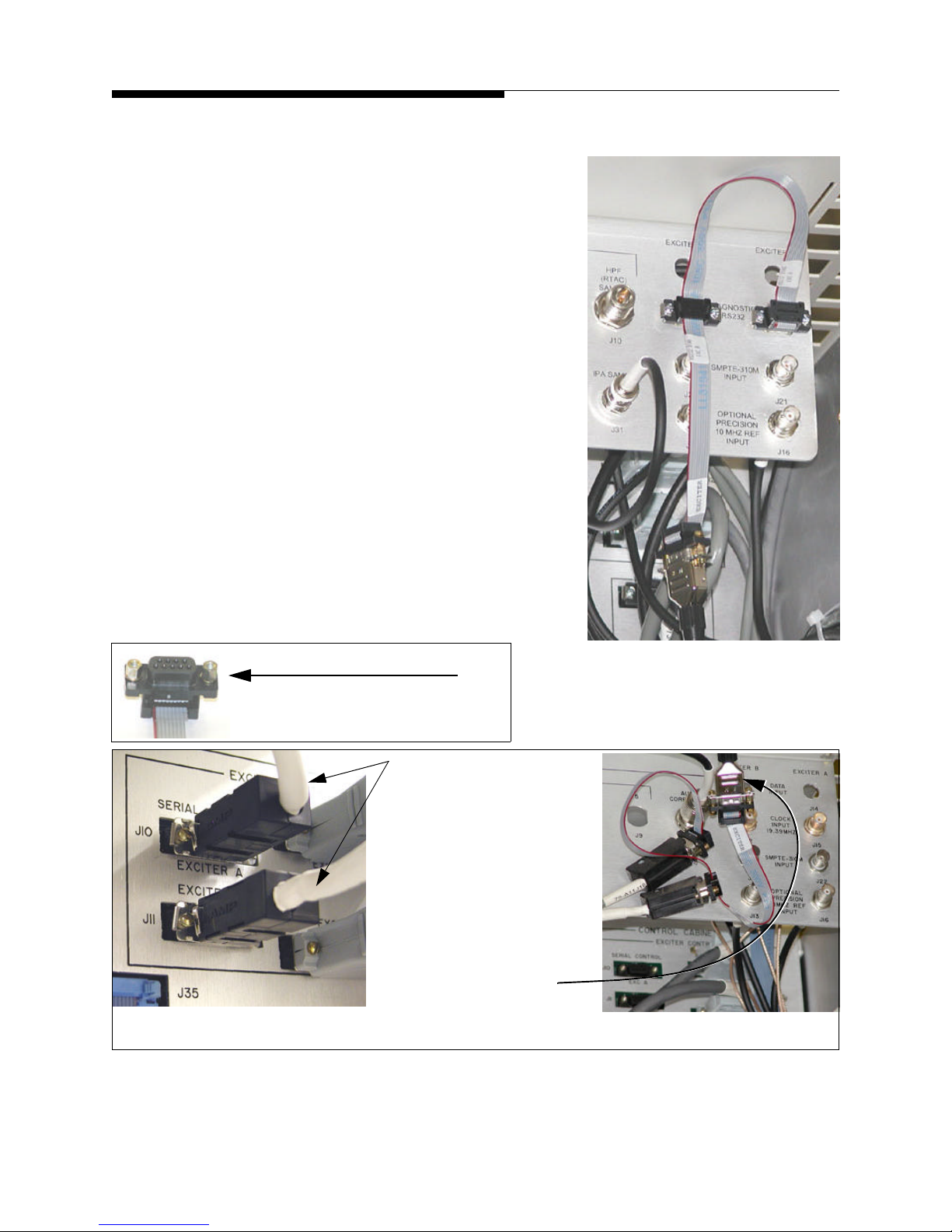
Section 2 Installation & Setup
There are 2 versions of Control Cabinet for the SigmaCD transmitter.
a. In the newer style cabinet the exciter serial
connections are already extended to the Customer I/O panel in the top rear area of the
Control Cabinet. Connect the “Y” splitter
cable to the Exciter A and Exciter B connections (both are male D connectors) on the
Customer I/O Panel and then connect the
eCDi™ serial cable (female to male) to the
“Y” cable as shown in Figure 2-5 (at right).
b. In older style cabinets, the exciter serial port
extension cables connect to the System I/O
Board behind the customer I/O Panel, see Figure 2-6A. In this case, disconnect the 2 serial
cables, labeled 76 and 77 (both are male D
connectors), from the System I/O Board and
connect the “Y” cable directly to the end of
the serial cables. Two (2) standoff kits are provided to allow the exciter cables and the Y
adaptor to be connected together. Then connect the eCDi™ serial cable (female to male)
to the “Y” connector. The completed assembly is shown in Figure 2-6B.
eCDi ™
Figure 2-5 Serial Connection
Y Adaptor with Stand-offs
for Dual CD-1A Exciters
(newer style cabinet)
1. Remove cables from
System I/O Board.
2. Add stand-off kits to
the Y adaptor cable and
connect to the exciter
cables that were just
removed.
3. Connect Y adaptor to
eCDi™ Exciter cable.
(A)
(B)
Figure 2-6 Serial Connection for Dual CD-1A Exciters (older cabinets)
2-8 888-2517-001 1/3/05
WARNING: Disconnect primary power prior to servicing.
Page 31

eCDi ™
Section 2 Installation & Setup
2.4.2 DiamondCD Series™ Transmitter
2.4.2.1 AC Power
If the eCDi™ is installed in the DiamondCD control cabinet, then it can be plugged into
the already present UPS (Un-interruptible Power Supply) near the bottom front of the
cabinet. Be careful not to un-plug the local transmitter control GUI computer that is
plugged in here.
2.4.2.2 Transmitter Serial Connection
Connect the serial port labeled “XMTR” on the eCDi™ to J6 (Harris Protocol #1) or
J35 (Harris Protocol #2) on the System I/O Board. A 50ft serial cable labeled “XMTR”
is provided in the cable kit. J6 and J35 are both female D connectors.
System I/O Board
Rear View
Figure 2-7 DiamondCD Serial Connections on System I/O Board
Make sure the dipswitches, S4 or S6 (depending on the port being connected) on the
front side of the System I/O Board are set for a direct computer connection, as shown in
Figure 2-4. Only switches 3 and 4 should be ON (in the up position).
S5
S4
S6
TCP/IP port (actually Com 3 from the
local GUI computer). Do not use this port
for eCDi™ connection.
J6 and J35 also called HP1 and HP2 (Harris
Protocol). Either of these ports can be used
for Remote GUI operation. Both ports are
configurable for DTE (Tx and Rx swapped)
or DCE (Tx and Rx thru).
Do not change. Switches set for ISP to Cabinet Controller
ON
J5
S5
J6
J35
These settings assume a pin for pin cable
5 6
1
4
2 3
ON
1
2 3
ON
1
2 3
8
7
Not used for eCDi™
4 5 678
S4
4 8
5 6
7
S6
J5 - TCP\IP
J6 - Harris Protocol #1
J35 - Harris Protocol #2
Figure 2-8 DiamondCD System I/O Board, Serial Port Switch Settings
1/3/05 888-2517-001 2-9
WARNING: Disconnect primary power prior to servicing.
Page 32

Section 2 Installation & Setup
2.4.2.3 DiamondCD Main Controller Setup
2.4.2.3.1 DiamondCD Software Requirements:
The DiamondCD transmitter has four (4) separate pieces of software/firmware which
must be at the following levels or higher before the eCDi™ can be connected:
• GUI Program Software for Windows® - GUI Version 3.0.0 (or higher)
• Main Controller Firmware - Version 3.0 (or higher)
• Cabinet Controller Firmware - Version 3.9 (or higher)
• PA Module Firmware - Version 2.14 (or higher)
NOTE:
The most important one of the above is the Main Controller firmware but the
transmitter software/firmware is a package and all 4 should be updated to the
most current release levels at the same time. Failure to update all 4 to the levels
on the upgrade disk or CD could cause operational conflicts.
eCDi ™
To check the Firmware revision levels on the transmitter see the Introduction section
of the DiamondCD Software manual, 888-2470-001. Complete upgrade procedures are
also located in the software manual. Section 1 explains how to upgrade the GUI
program, while Section 3 explains how to do the ISP (In-System Programming) to
update the Main Controller, Cabinet Controller and PA Modules.
2.4.2.3.2 Main Controller Dipswitch Settings
To deactivate the Main Controller password requirement (necessary for eCDi™
connection) set the S2 dipswitch on the transmitter Main Controller Board as follows:
• If eCDi™ is being connected to HP1 (J6), set S2-7 to ON
• If eCDi™ is being connected to HP2 (J35), set S2-8 to ON
NOTE:
If Remote GUI connection is not being used it is also recommended that the
Remote Access password in the Local GUI computer be set to Null (clear the
password and press enter). See the DiamondCD Software Manual for more
information.
2-10 888-2517-001 1/3/05
WARNING: Disconnect primary power prior to servicing.
Page 33

eCDi ™
Section 2 Installation & Setup
2.4.2.4 Exciter Connections
APEX Exciters
To connect the eCDi™ to an APEX™ exciter requires a standard ethernet cable (not
cross-over) with RJ-45 connectors on each end. Two (2) 50ft ethernet cables labeled
EX1 and EX2 have been provided. Connect the exciter(s) to the RJ-45 ports on the back
of the eCDi™ labeled EX1 and EX2 in Figure 2-2.
IMPORTANT:
The IP address and Subnet mask must also be set up in the APEX exciter. See
"2.5 APEX Exciter Setup" on page 2-22.
NOTE:
When routing the ethernet cable to the back of the exciter, make sure to follow the
cable supports and wiring harness to allow the exciters to be pulled completely
out the front to the extent of the rack slides. Cable ties have been provided to
secure the cables to prevent damage when the exciter is pulled out for service.
CD-1A Exciters
CD-1A exciters connect to the eCDi™ via serial port. Connect the provided 50ft serial
cable labeled “EXCITER” to the serial port labeled “EXCITER” on the eCDi™. Route
the cable into the back of the GUI control cabinet in the transmitter. This cable connects
to the provided Y adaptor in the transmitter control cabinet. The Y adaptor allows 2
exciters to be connected to the eCDi™ on the same serial port. Connection of the Y
adaptor cable depends on the age of the control cabinet. Both types of cabinet are
covered on the next page.
NOTE:
The exciters can both be connected to the same serial cable because they only have
access to the serial port if they are the active or ON-AIR exciter in the transmitter.
1/3/05 888-2517-001 2-11
WARNING: Disconnect primary power prior to servicing.
Page 34

Section 2 Installation & Setup
There are 2 versions of Control Cabinet for the DiamondCD transmitter.
a. In the newer style cabinet the exciter serial
connections are already extended to the
Customer I/O panel in the top rear area of
the Control Cabinet. Connect the “Y” splitter cable to the exciter A and Exciter B connections (both are male D connectors) on
the Customer I/O Panel and then connect the
eCDi™ serial cable (female to male) to the
“Y” cable as shown in Figure 2-9.
b. In older style cabinets, the exciter serial port
extension cables connect to the System I/O
Board behind the customer I/O Panel, see
Figure 2-10A. In this case, disconnect the 2
serial cables, labeled 76 and 77 (both are
male D connectors), from the System I/O
Board and connect the “Y” cable directly to
the end of the serial cables. Two (2) standoff
kits are provided to allow the cable and the
Y adaptor to be connected together. Then
connect the eCDi™ serial cable (female to
male) to the “Y” connector. The completed
assembly is shown in Figure 2-10B.
eCDi ™
Figure 2-9 Serial Connection
Y Adaptor with Stand-offs
for Dual CD-1A Exciters
(newer style cabinet)
1. Remove cables from
System I/O Board.
2. Add stand-off kits to
the Y adaptor cable and
connect to the exciter
cables that were just
removed.
3. Connect Y adaptor to
eCDi™ Exciter cable.
(A)
(B)
Figure 2-10 Serial Connection for Dual CD-1A Exciters (older cabinets)
2-12 888-2517-001 1/3/05
WARNING: Disconnect primary power prior to servicing.
Page 35

eCDi ™
Section 2 Installation & Setup
2.4.3 PlatinumCD and Platinum Analog TV Transmitters
Since the only installation differences between PlatinumCD (DTV transmitter) and the
Platinum Analog transmitter is the exciter, both transmitters will be discussed as one.
2.4.3.1
Mounting and AC Power
The eCDi™ unit can be mounted in the Platinum Control cabinet if there is room to
mount it, however there are no rack rails on which to mount the eCDi™ unit. It is
therefore recommended that the eCDi™ unit be mounted in an equipment rack nearby,
or at least within the 50ft maximum limit of the serial cable connection.
NOTE:
If the unit is mounted into the transmitter, ac power may be obtained by
connecting to the same terminals on the 1TB2 terminal strip as the exciters, using
a moulded ac power cord with a pigtailed end. 1TB2 will always have 220/
240Vac present.
!
WARNING:
DISCONNECT PRIMARY POWER FROM THE CONTROL CABINET AT THE MAIN AC
WALL DISCONNECT BEFORE REMOVING SAFETY SHIELDS OR ATTEMPTING TO
MAKE ANY CONNECTIONS.
2.4.3.2
Connect the
Transmitter Serial Connection
9 pin to 25 pin null modem adaptor to J9 (a 25 pin female D connector) on
the rear of the Monitor Board in the Platinum control cabinet. Next connect the provided
9 pin in-line surge protector to the adaptor just installed.
lug on the surge protector to the cabinet.
Finally connect one end of the provided 50ft
Be sure to connect the ground
serial cable labeled “XMTR” to the 9 pin surge protector and the other end to the serial
port on the eCDi™ labeled “XMTR.” Use the provided cable ties to support the cable
and adaptors to prevent stress on the Monitor Board connection.
!
CAUTION:
THE RS232 SERIAL CONNECTION ON THE PLATINUM MONITOR BOARD HAS NO
SURGE PROTECTION. A SURGE PROTECTOR IS PROVIDED WITH THE
INSTALLATION KIT. THE SURGE PROTECTOR SHOULD BE MOUNTED ON THE
TRANSMITTER END OF THE CABLE AND BE GROUNDED TO THE TRANSMITTER
CABINET. FAILURE TO INSTALL THE SURGE PROTECTOR COULD RESULT IN
SERIOUS DAMAGE TO THE PLATINUM MONITOR BOARD.
1/3/05 888-2517-001 2-13
WARNING: Disconnect primary power prior to servicing.
Page 36

Section 2 Installation & Setup
Table 2-1 DB9 to DB25 Null Modem Conversion Cable Connections
Serial Cable - Null Modem Conversion DB9 to DB25
DB9 DTE Device (Computer) Connects To DB25 DTE Device (Transmitter)
eCDi ™
Pin 2 Rx
Pin 3 Tx
Pin 5 Signal GND
When making a cable for this connection, these are the only connections required.
?
?
?
Pin 2 Tx
Pin 3 Rx
Pin 7 Signal GND
2.4.3.3 Exciter Connections
HX-1V Analog Exciters
The eCDi™ does not connect to the HX-1V analog exciters.
APEX Exciters
To connect the eCDi™ to an APEX™ exciter requires a standard ethernet cable (not
cross-over) with RJ-45 connectors on each end. Two (2) 50ft ethernet cables labeled
EX1 and EX2 have been provided. Connect the exciter(s) to the RJ-45 ports on the back
of the eCDi™ labeled EX1 and EX2 in Figure 2-2.
IMPORTANT:
The IP address and Subnet mask must also be set up in the APEX exciter. See
"2.5 APEX Exciter Setup" on page 2-22.
NOTE:
When routing the ethernet cable to the back of the exciter, make sure to follow the
cable supports and wiring harness to allow the exciters to be pulled completely
out the front to the extent of the rack slides. Cable ties have been provided to
secure the cables to prevent damage when the exciter is pulled out for service.
CD-1A Exciters
CD-1A exciters connect to the eCDi™ via serial port. Since the eCDi™ unit will be
mounted external to the control cabinet in most installations the recommended
connection is as follows:
a. Connect the provided, 10ft, 9 pin serial cables labeled RS232 Diag EXC A and
RS232 Diag EXC B to the RS232 ports on the back of each exciter and route the
cables with the exciter wiring harness. See Figure 2-11 for connection drawing.
2-14 888-2517-001 1/3/05
WARNING: Disconnect primary power prior to servicing.
Page 37

eCDi ™
with Stand-offs
Section 2 Installation & Setup
NOTE:
When routing the serial cable to the back of the exciters, make sure to follow the
cable supports and wiring harness to allow the exciters to be pulled completely
out the front to the extent of the rack slides. Cable ties should be used to secure
the serial cable to prevent damage when the exciter is pulled out for service.
b. Connect the provided Y adaptor to the ends of
both 10ft. cables. Two (2) stand-off kits are
provided and should be attached to the Y adap-
Y Adaptor
tor cable as shown here.
c. Connect the supplied 50ft. cable labeled
“Exciter” from the Y adaptor “Exciter” port to the serial port labeled “Exciter” on
the eCDi™ unit.
NOTE:
The exciters can both be connected to the same serial cable because they only
have access to the serial port if they are the active or ON-AIR exciter in the
transmitter.
IMPORTANT:
If there is only one (1) CD-1A exciter to be connected, then simply omit the “Y”
splitter cable in the previous instructions and connect the 50ft. eCDi™ serial
cable labeled “Exciter” directly from the eCDi™ unit to the exciter.
CD-1A
RS232
10ft. Serial Cable
Exciter A
CD-1A
RS232
10ft. Serial Cable
Exciter B
NOTE: Be sure to route these cables
along the existing wiring harness
to the exciters
NOTE: attach the standoff kits to the Y
adaptor cable. This allows the serial cables to
be secured directly to the Y adaptor.
Y Adaptor Cable
eCDi™
Exciter Port
50ft. Serial Cable
Figure 2-11 Connection Drawing for Dual CD-1A Exciters
1/3/05 888-2517-001 2-15
WARNING: Disconnect primary power prior to servicing.
Page 38

Section 2 Installation & Setup
?
2.4.3.4 Platinum TV Transmitter Settings
There are 2 settings in the Platinum TV transmitter which must be setup before the
eCDi™ will connect:
• Baud Rate - 9600 Baud
• Control and System Passwords - Null (no passwords set)
These controls are accessed via the Platinum Control Panel (plasma display) by
selecting:
SETUP ? SENTRY
This will bring up the display shown below in Figure 2-12. Once the baud rate is set and
any passwords cleared, select SAVE.
INFO:
eCDi ™
If the SENTRY™ option is not available under the setup menu, the Platinum
Monitor board will require a software and memory upgrade. These components
are included in the eCDi™ installation kit for the Platinum Analog TV
transmitters. See " Appendix G Platinum TV Monitor Board Upgrade" to decide
if the upgrade is necessary and for detailed instructions on performing the
upgrade. This upgrade may also be required for some Platinum CD Digital TV
transmitters.
NOTE:
Set Baud Rate to 9600 and
make sure that no passwords are
set.
Figure 2-12 Platinum Control Panel
2-16 888-2517-001 1/3/05
WARNING: Disconnect primary power prior to servicing.
Page 39

eCDi ™
Section 2 Installation & Setup
2.4.4 Ranger Transmitter
2.4.4.1
If the eCDi™ unit is mounted in the Ranger cabinet, it should be mounted near the top
of the cabinet and can be plugged into the power strip in the rear of the transmitter.
Alternately, the eCDi™ can also be mounted in a nearby equipment rack.
2.4.4.2
Connect the serial port labeled “XMTR” on the eCDi™ to
Board uing the provided
used depending on where the eCDi™ is mounted).
Mounting and AC Power
Transmitter Serial Connection
J7 on the Main Controller
10ft or 50ft serial cable labeled “XMTR” (either cable can be
2.4.4.3 Exciter Connections
CD-1A Exciter
Connect the provided 10ft or 50ft, 9 pin, serial cable labeled “Exciter” to the serial port
on the eCDi™ labeled “Exciter.” Connect the other end to the RS232 serial port on the
back of the CD-1A exciter (it is the only 9 pin D connector and is labeled Diagnostic
Port on some exciters).
NOTE:
When routing the serial cable to the back of the exciter, make sure to follow the
cable supports and wiring harness to allow the exciters to be pulled completely
out the front to the extent of the rack slides. Cable ties should be used to secure
the serial cable to prevent damage when the exciter is pulled out for service.
APEX Exciters
To connect the eCDi™ to an APEX™ exciter requires a standard ethernet cable (not
cross-over) with RJ-45 connectors on each end. Use the provided 10ft or 50ft ethernet
cable labeled EX1 to connect the exciter ethernet port to the ethernet port on the back of
the eCDi™ labeled EX1 in Figure 2-2.
IMPORTANT:
The IP address and Subnet mask must also be set up in the APEX exciter. See
"2.5 APEX Exciter Setup" on page 2-22.
NOTE:
When routing the ethernet cable to the back of the exciter, make sure to follow the
cable supports and wiring harness to allow the exciters to be pulled completely
out the front to the extent of the rack slides. Cable ties have been provided to
secure the cables to prevent damage when the exciter is pulled out for service.
1/3/05 888-2517-001 2-17
WARNING: Disconnect primary power prior to servicing.
Page 40

Section 2 Installation & Setup
2.4.5 Platinum Z FM and IBOC Transmitters
Since the only difference between the Platinum Z FM analog and the Platinum Z IBOC
transmitter is the exciter (at least as far as the eCDi™ installation is concerned) these
transmitters will be discussed as one.
eCDi ™
2.4.5.1
The eCDi™ unit can only be mounted in the transmitter if it has a single exciter. This
would also require bringing an external source of 110/220Vac into the transmitter.
2.4.5.2
Connect the provided 9 pin to 25 pin null modem adaptor to J21 on the Display/
Backplane Board in the transmitter control unit. J21 is on the left side of the Display/
Backplane board right next to the Master Controller, see Figure 2-13 for location of the
connector.
Connect one end of the provided 10ft or 50ft serial cable labeled “XMTR” (either cable
can be used depending on where the eCDi™ is mounted) to the serial port on the
eCDi™ labeled “XMTR”. Connect the other end to the 9 pin to 25 pin null modem
adaptor previously connected to J21 on the Display/Backplane Board. See Table 2-2 for
DB9 (DTE) to DB25 (DCE) conversion pinouts.
Mounting and AC Power
IMPORTANT:
Do not plug the eCDi™ into the spare ac cord that is already wired in all Z FM
Transmitters for the second exciter. This cord is 220/240Vac, which is okay, but is
switched with the transmitter on/off switch, which is unacceptable.
Transmitter Serial Connection
See Close-up at right
Figure 2-13 Platinum Z Controller Serial Connection
2-18 888-2517-001 1/3/05
WARNING: Disconnect primary power prior to servicing.
J21
Page 41

eCDi ™
Section 2 Installation & Setup
Table 2-2 DB9 to DB25 Null Modem Cable Connections
Serial Cable - Straight Conversion DB9 to DB25
DB9 DTE Device (Computer) Connects To DB25 DCE Device (Transmitter)
Pin 1 DCE
*Pin 2 Rx
*Pin 3 Tx
Pin 4 DTE (DTR)
*Pin 5 Signal GND
Pin 6 DSR
Pin 7 RTS
Pin 8 CTS
Soldered to DB9 metal - Shield
*The connections in the shaded rows are the only required connections.
?
?
?
?
?
?
?
?
?
Pin 8
*Pin 3 Rx
*Pin 2 Tx
Pin 20 DTE (DTR)
*Pin 7 Signal GND
Pin 6 DSR
Pin 4 RTS
Pin 5 CTS
Pin 1 Shield to Frame GND
2.4.5.3 Exciter Connections
No exciter connection required. Exciter information is gathered via the transmitter
controller. This applies for all Platinum Z exciters:
• Dexstar™ IBOC Exciter
• Digit™
• SuperCiter Analog Exciter
1/3/05 888-2517-001 2-19
WARNING: Disconnect primary power prior to servicing.
Page 42

Section 2 Installation & Setup
2.4.6 Atlas Transmitter
The following applies to either the Atlas Digital DVB-T transmitter or the Atlas Analog
(NTSC or PAL) transmitter as they both have the same Main Controller hardware.
2.4.6.1 Atlas Digital Mounting and AC Power
The eCDi™ can be mounted inside the transmitter cabinet if there is sufficient room. In
this case the ac power may be obtained from TB6 pins 1, 2 and 3 using a standard
moulded ac plug with a pigtail at the opposite end for connection to the terminal strip.
TB6-1 and 2 come from a step down transformer and are therefore interchangeable.
The ac connections to the transmitter are as follows:
• TB6 - 1 Line/N
eCDi ™
• TB6 - 2 Line/N
eCDi™ Power supply connector
• TB6 - 3 GND
2.4.6.2 Atlas Analog Mounting and AC Power
The eCDi™ can be mounted inside the transmitter cabinet and is actually shown in the
Atlas Analogue Overall Wiring Diagrams which came with the transmitter. The AC
cord for the eCDi™ is prewired into the Atlas Analogue cabinet along with the serial
cable to the controller (W9).
2.4.6.3
For the Atlas Digital, connect the serial port labeled “XMTR” on the eCDi™ to
the Main Controller Board using the provided
(either cable can be used depending on where the eCDi™ is mounted).
For the Atlas Analogue, cable W9 is prewired into the cabinet and simply needs to be
connected to the eCDi™ “XMTR” port. See the Atlas Analogue Wiring Diagram.
Transmitter Serial Connection
J7 on
10ft or 50ft serial cable labeled “XMTR”
2.4.6.4 Exciter Connections
No exciter connection required. Exciter information is gathered via the transmitter
controller.
2-20 888-2517-001 1/3/05
WARNING: Disconnect primary power prior to servicing.
Page 43

eCDi ™
Section 2 Installation & Setup
2.4.7 PowerCD™ Digital UHF Transmitter
The “Display Unit” in the PowerCD transmitter is actually a modified eCDi™ which
has a local touchscreen interface attached to its front panel.
For information about operating the local touchscreen interface see the “PowerCD
Transmitter Operators Manual” 888-2475-001.
The eCDi™ (aka the PowerCD Display Unit) comes pre-installed and configured in the
powerCD. However, you will still need to go through the configuration screens to
customize the unit for your site. This includes making sure the time and date are correct,
adding users and setting passwords, setting Email alert addresses, fault log filters etc...
If you are going to use an SNMP Network Manager program like Recon™ or the Harris
Broadcast Manager, you will want to pay close attention to the SNMP configuration
screens.
See "2.8 eCDi™ Configuration" on page 2-26 to check and set your configuration. It is
important that you check the information in all of the configuration screens to see if it
applies to your site.
It is also important to note that the PowerCD transmitter uses one eCDi™ in the Driver
cabinet and one in each PA Cabinet. A router, with a 4 port switch, is installed in the
Driver cabinet and is factory configured to provide access to all of the eCDi’s in the
transmitter using a single internet IP address (using port forwarding). While each
eCDi™ could actually be placed directly on a network with its own IP address, the
router also provides a firewall at the transmitter site to protect the transmitter. For more
information on setting up the router, see the “PowerCD Transmitter Operators Manual”
888-2475-001.
1/3/05 888-2517-001 2-21
WARNING: Disconnect primary power prior to servicing.
Page 44

Section 2 Installation & Setup
?
2.5 APEX Exciter Setup
IMPORTANT:
The APEX exciter software must be 4.0 or later to activate the Ethernet port for
use with eCDi™. This software (along with the Harris ISP program and programming instructions) can be obtained via download from the Harris Premier web
site or by contacting Harris Technical support. To check the software revision of
your APEX press the “System Control” button on the APEX front panel. This
will bring up the screen shown in Figure 2-14. If the software revision is not 4.0
or later, it must be upgraded using the Harris ISP (In-System Programming) software, and the files downloaded from the web site, before it will communicate
with the eCDi™.
eCDi ™
Control Software
revision
NOTE:
For more information regarding APEX upgrades, see the APEX technical
manual, 888-2491-001.
INFO:
The Harris ISP (In-System Programming)2.0 software, provided at no cost, is
used to update the firmware memory in the APEX exciter via the serial port on
the front or back of the unit. The Harris ISP 2.0 program, upgrade software and
instructions can be downloaded from the Harris Premier Website. Please note
that Harris ISP 2.0 must be used. Harris ISP 1.10, which comes loaded on the
Diamond and Sigma transmitter GUI, is not compatible with APEX. Do not load
Harris ISP 2.0 on a Diamond and/or Sigma transmitter GUI as it is not backward
compatible.
Figure 2-14 APEX Software Revision Check
2-22 888-2517-001 1/3/05
WARNING: Disconnect primary power prior to servicing.
Page 45

eCDi ™
Section 2 Installation & Setup
2.5.1 Setting APEX IP Address
If one or more APEX exciters are to be connected to the eCDi™, it is necessary to set
an IP Address and Subnet Mask for each exciter. Go to the display on the front of the
APEX exciter and select Home - Setup - Serial I/O. This will bring up the screen in
Figure 2-15A. Select NEXT to open the Ethernet Setup screen shown in Figure 2-15B.
Click on each number to bring up the edit window and change them one at a time to that
shown here. The exciter will have to be shut off and then turned back on before the
changes will take effect.
The following IP addresses were implemented as of eCDi™ software revision 2.6.K or
higher. For all previous versions see the NOTE below.
• IP Address: 192.168.217.200
• Subnet Mask: 255.255.255.0
Set the second exciter to:
• IP Address: 192.168.217.201
• Subnet Mask: 255.255.255.0
NOTE:
For all eCDi™ software revisions
before 2.6.K use the following IP
addresses for the APEX exciter:
Exciter 1: 192.168.0.200
Exciter 2: 192.168.0.201
Select Next
(A)
NOTE:
The exciter will have to be shut off (ac
power removed) and then turned back
on before the changes will take effect.
Figure 2-15 APEX Exciter Ethernet Setup Screen
1/3/05 888-2517-001 2-23
WARNING: Disconnect primary power prior to servicing.
(B)
Page 46

Section 2 Installation & Setup
2.6 CD-1A Electronic Serial Number Reset
The CD-1A has an Electronic Serial number or ESN. If this has been set to something
other than the factory default value (this normally only happens if the CD-EYE
program has been used with the CD-1A), it must then be reset before the eCDi™ will be
able to communicate with the CD-1A. To reset the ESN, pull the exciter all the way out
on its rack slides. Open the exciter by pulling up on the top half of the exciter. Use the
prop arm to hold up the upper half of the exciter. Dipswitch S3-5 and S3-6 should be
placed in the OFF position. Then switch S3-5 to the ON position and then back to OFF.
Finally, press the reset button located on the same board as S3. The ESN is now reset
and the CD-1A should communicate with the eCDi™. Dipswitch S3 is located near the
front of the exciter on the Corrector Controller board. See Figure 2-16 below for the
location of dipswitch S3.
NOTE:
For dual exciter systems, don’t forget to reset the second exciter as well.
eCDi ™
Figure 2-16 CD-1A Exciter, S3 Location
2-24 888-2517-001 1/3/05
WARNING: Disconnect primary power prior to servicing.
Dipswitch S3
Reset Switch
Page 47

eCDi ™
2.7 Initial Turn-On
Once the unit is installed, it is ready to be turned on. The power switch is located on the
back of the unit on the right hand side.
At this point the following connections should already be made:
1. AC power connection to the eCDi™ unit (110/220Vac).
2. Serial connection to the transmitter controller.
3. Serial or Ethernet connection (whichever is required) to the exciter(s).
4. Ethernet Uplink jumper on the back of the eCDi™ unit from the LAN port
to the first port on the internal switch (see Figure 2-2).
5. Ethernet connection from the WAN port on the eCDi™ to a hub on the Sta-
tion LAN or WAN. A 50ft RJ-45 cable labeled “WAN” is provided for this
connection.
Section 2 Installation & Setup
NOTE:
The WAN connection will not be able to be accessed until after the eCDi™
configuration is finished in the following paragraphs. Configuration requires
connecting an external computer to the RJ-45 Config port on the front of the
eCDi™ using the provided 6ft ethernet cable that is labeled “Configure”.
IMPORTANT:
All ethernet cables connected to the eCDi™ should be shielded twisted pair
(STP) category 5 (Cat 5) cable. All cables supplied with the eCDi™ are shielded.
1/3/05 888-2517-001 2-25
WARNING: Disconnect primary power prior to servicing.
Page 48

Section 2 Installation & Setup
IMPORTANT!
2.8 eCDi™ Configuration
Now that the eCDi™ unit is turned on, connect an external computer with a 10 base T
network connection directly to the ethernet port on the front of the eCDi™ using the
provided ethernet cable labeled “Configure.” This port must be used for the initial
configuration of the unit. As of eCDi™ software Rev 2.6.K, the configuration port has a
fixed IP address of 192.168.217.254 or a name of ecdi-local on all units.
STEP 1 The eCDi™ supports DHCP which means the computer to be connected
for configuration can be set to “Obtain an IP Address Automatically” as
shown in Figure 2-17. In this mode eCDi™ will assign the remote
NOTE: The
Configuration port
IP address for any
software revision
before 2.6.K is
192.168.0.254 and
the computer must
be set to:
192.168.0.1
255.255.255.0
computer an IP address when it connects.
Right-click on Network Neighborhood and select Properties. This can
•
also be accessed by selecting “Network and Dialup Connections” in
the Control Panel.
Next, right-click on the LAN connection and select Properties again.
•
•Click on Internet Protocol (TCP\IP) and click on Properties again.
•This brings up the IP address screen. Select “Obtain an IP address auto-
matically” as shown. Click OK and close all windows and re-boot.
eCDi ™
?
?
Right Click
and select
Properties
Click on Internet Protocol
and then click Properties
Note: If the computer is
changed to DHCP mode from a fixed IP address, the
computer may have to be re-started
Figure 2-17 Changing the Remote Computer IP Address
Make a note of the computer
settings before making any
changes, so it can be easily reset
after configuring the eCDi™.
?
2-26 888-2517-001 1/3/05
WARNING: Disconnect primary power prior to servicing.
Page 49

eCDi ™
Section 2 Installation & Setup
STEP 2 To access the eCDi™ and the configuration screens, open a browser
(such as IE or Netscape) and type one of the following into the Address
bar of the browser and press Enter: (these addresses are only
implemented in eCDi™ software revision 2.6.K and above)
http://192.168.217.254
http://ecdi-local (this is a fixed eCDi™ domain name on the
configuration port)
NOTE:
If you have an eCDi™ software revision before 2.6.K then the configuration port
IP address is http://192.168.0.254
This will bring up the screen shown in Figure 2-18. Do not login to the
application yet.
Click here
Then click here
Do not login
here at this time
Figure 2-18 eCDi™ Login Screen
1/3/05 888-2517-001 2-27
WARNING: Disconnect primary power prior to servicing.
Page 50

Section 2 Installation & Setup
2.8.1 Troubleshooting Tips
1. When using DHCP, connection problems can occur if the computer fails to
release it old IP address. To check this: (Do not type the quote marks)
a. Open a DOS Prompt and type “ipconfig” and press enter. This
should return an IP address in the range of 192.168.217.1 to
192.168.217.49 . If not, then in the same DOS window type “ipconfig/release” and press enter. Then type “ipconfig/renew” and press
enter.
b. Type “ipconfig” again to verify an address has been issued in the
range given above.
NOTE:
If connection cannot be made, try
setting the remote computer to a
fixed IP address. Select “Use the
following IP address” as shown to
the right. Then enter the IP address
192.168.217.1 with a subnet mask of
255.255.255.0 (this address is only
valid if you have eCDi™ software
revision 2.6.K or higher). Try Step 2
again. If it still does not work, try
several different ethernet cables.
eCDi ™
NOTE:
If you have an eCDi™ software
revision before 2.6.K then enter you
must set a fixed IP address of
192.168.0.1 with a subnet mask of
255.255.255.0
2-28 888-2517-001 1/3/05
WARNING: Disconnect primary power prior to servicing.
Page 51

eCDi ™
?
NOTE:
It could be several
minutes before this
screen pops up.
Section 2 Installation & Setup
IMPORTANT:
To run eCDi™ requires that the Java 2 Runtime Environment plug-in be loaded.
If the computer used to access the eCDi™ does not have this plug-in installed, it
will be automatically downloaded from the eCDi™ and the screen in Figure 2-19
will appear asking if you want to load the plug-in. Select Yes and then follow the
on-screen instructions to load the plug-in. This will not require a computer restart
and will only happen the first time a computer logs on to eCDi™.
Figure 2-19 Java 2 Runtime Environment Plug-in
INFO:
To get the computer to use the latest plug-in, it is sometimes necessary to unload
all previous versions of the Java Runtime Environment using Add/Remove
programs in the Windows Control Panel. Once all versions are removed,
accessing the eCDi™ will automatically load it again.
STEP 3 Click on “Service eCDi” as shown on the left side of
the login screen in Figure 2-18. This provides
access to the Configure and Upgrade options. Click
on Configure. This will bring up the Configuration
Login screen in Figure 2-20.
1/3/05 888-2517-001 2-29
WARNING: Disconnect primary power prior to servicing.
Page 52

Section 2 Installation & Setup
CAUTION:
The eCDi™ will only ask for the
administrator password once per
session. To prevent unauthorized
access to the configuration, the
browser should be closed and
then re-opened, which then
requires that the administrator
password be entered again.
Figure 2-20 Configuration Login Screen (Administrator password required)
STEP 4 Type in the following and then press OK:
eCDi ™
STEP 5 When the login is accepted the main menu will appear as shown in
The PRESET
button resets all
configuration
settings back to
factory defaults
User Name - admin
Password - admin (This can and should be changed immediately, once
the configuration screens are accessed).
Figure 2-21. Click on General to open the screen in Figure 2-22.
Figure 2-21 Main Configuration Menu Screen
2-30 888-2517-001 1/3/05
WARNING: Disconnect primary power prior to servicing.
Page 53

eCDi ™
Section 2 Installation & Setup
Figure 2-22 General Configuration Screen
STEP 6 Set a new administrator password. Although shown checked here, the
“Allow remote administration” checkbox should only be checked if you
want to be able to access these configuration screens via the station LAN
or WAN. If this box is not checked, then only a local connection to the
front of the eCDi™ unit will allow access to the configuration screens.
STEP 7 Set the Location of the box and/or any call letters. This is used by the
browser applet, email and SNMP.
STEP 8 Set the correct time and date. This information is used for time stamping
of the metering and fault logs. Use the pull down menu to select the
appropriate time zone.
STEP 9 Time Server IP (recommended): If there is a time server available on the
local network it will be auto-detected or can be set manually. An internet
time server could also be used. If no time server is specified, the internal
pc clock will be used and will require manual setting at frequent
intervals for accurate time stamping of logs.
NOTE:
Time Zone setting will affect the time even when a Time Server is used.
STEP 10 When all changes are made, press Submit and then press Back to return
to the main menu.
1/3/05 888-2517-001 2-31
WARNING: Disconnect primary power prior to servicing.
Page 54

Section 2 Installation & Setup
?
STEP 11 Select Feature Key on the main menu to get the screen shown in Figure
2-23. The Feature key number is normally entered at the factory before
shipment, but is also recorded in the Factory Test Data included with the
unit. If not already entered, type in the 40 character key to setup the
eCDi™ for the correct hardware and features.
STEP 12 Once the key is entered, click on Submit and then verify that the correct
hardware and features are displayed. Depending on the transmitter type
(chosen by the feature key) you may also need to select the correct type
of exciter for each exciter position. If you change the exciter selection,
click on Submit to finish the Feature Key configuration.
INFO:
The Feature Key is an encrypted code word that contains all of the hardware
configuration, such as transmitter type and any add on features such as
Performance Monitoring. The Feature Key is coded to the hardware in the
eCDi™ and therefore can only be used on a specific eCDi™ unit.
NOTE:
Other than the exciter selections, the text boxes below the Feature Key box are
not editable and can only be changed with a different Feature Key. If the
transmitter hardware or features purchased do not match the information
displayed, contact technical support.
eCDi ™
NOTE:
This screen is only
an example. Do not
use this for your
installation.
The exciter type
must be chosen on
site depending on
the equipment
present. If no
exciter is to be
controlled, then
select None/Other.
STEP 13 Once the information is entered, submitted and verified, press Back to
These features are chosen
by the Feature Key and
connot be changed without
changing the Key
Figure 2-23 Feature Key Configuration Screen
return to the main menu. Click on User mgmt to access the User
Management screen in Figure 2-24.
2-32 888-2517-001 1/3/05
WARNING: Disconnect primary power prior to servicing.
Page 55

eCDi ™
?
Section 2 Installation & Setup
STEP 14 To add users, Type in a Username and password and then select their
level of access: Engineer, Operator or Monitor (none of these can
change configuration). Users can be deleted using the Delete user pull
down menu.
INFO:
The 3 password levels set the Web GUI transmitter control access level.
Engineer provides access to all Web GUI screens and control functions.
Operator provides access to all GUI screens, but limits functionality to basic On,
Off, Raise and Lower power (these functions depend on the transmitter).
Monitor provides access to all screens but prevents any transmitter control.
NOTE:
Passwords are case sensitive, but Usernames are not.
STEP 15 When all changes are made, press Submit and then press Back to return
to the main menu. Click on Network to access the screen in Figure 2-25.
1/3/05 888-2517-001 2-33
WARNING: Disconnect primary power prior to servicing.
Figure 2-24 User Management Screen
Page 56

Section 2 Installation & Setup
STEP 16 If you are connecting to a network (via the WAN connection on the
eCDi™) that supports DHCP then click the “dhcp” button and the dhcp
server should assign all of the required IP addresses automatically.
Problems with this function should be directed to the station network
administrator.
If the network does not use dhcp, or if it is desired to have a static IP
address, then select “static” and manually enter at least the IP Address
and the Subnet mask.
eCDi ™
NOTE:
The information
in this picture is
for example only.
Figure 2-25 Network Configuration Screen
STEP 17 When all changes are made, press Submit and then press Back to return
to the main menu. Click on SNMP to access the screen in Figure 2-26.
IMPORTANT:
The SNMP Configuration screen only needs to be set up if an SNMP Network
Manager is going to be used to access the eCDi™. If the web browser is going to
be the only interface then skip to STEP 27, to continue the eCDi™ configuration.
NOTE:
If your network supports Default DNS then the host name can be used to access
the eCDi™. IF not, the IP address must be used.
Example: http://137.237.242.26 or http://my-ecdi.bpd.harris.com or whatever is
enabled in HostName and Domain Name).
2-34 888-2517-001 1/3/05
WARNING: Disconnect primary power prior to servicing.
Page 57

eCDi ™
STEP 18 SNMP Manager Configuration. In the “Add IP Address” box, type in the
STEP 19 SNMP Agent Configuration. Type in the name of the “rw community”
STEP 20 Checking the “ENABLE SET” checkbox sets this eCDi™ to accept
STEP 21 Select the appropriate version of traps for your SNMP system by
NOTE:
See Section 6 for
additional SNMP
information.
Section 2 Installation & Setup
IP addresses of the computers to which all SNMP trap messages will be
sent. To delete a trap destination, use the “Delete IP Address” pull down
menu and select the destination to be deleted.
(read/write Community).
SNMP SET (remote control) commands (this is a high security risk
unless SNMP V3 is used).Un-checking this box means that an SNMP
manager will only be able to provide status and monitoring (GET
commands).
selecting v1 Traps or v2 Traps (SNMP Version 1 or SNMP Version 2).
NOTE:
See Section 7 for
Firewall port
information
Figure 2-26 SNMP Configuration
STEP 22 When all changes are made, press Submit and then press Back to return
to the main menu.Click on SNMP v3 to access the screen in Figure 2-28.
NOTE:
When “Apply” is pressed on the Configuration main menu (see Figure 2-21) the
eCDi™ will send test SNMP Trap messages to all specified SNMP Network
Managers.
1/3/05 888-2517-001 2-35
WARNING: Disconnect primary power prior to servicing.
Page 58

Section 2 Installation & Setup
STEP 23 If you are using SNMP v3 (version 3) then User Names and Passwords
must be entered for each user. Simply type the User Name and Password
into the text boxes and press Submit. Users may be deleted by using the
delete user pull down menu. To edit a user requires that it simply be
deleted and re-entered.
STEP 24 Next select the type of security functionality to be used by selecting
either “MD5 & DES” for authentication and encryption or select
“Noauth and Noenc” for no authorization or encryption.
STEP 25 Lastly, select the V3 only checkbox to prevent V1 and V2 logins that
would bypass the username and password security of V3.
NOTE:
See Section 6 for
additional SNMP
information.
eCDi ™
STEP 26 When all changes are made, press Submit and then press Back to return
to the main menu. Click on Email to access the screen in Figure 2-28.
2-36 888-2517-001 1/3/05
WARNING: Disconnect primary power prior to servicing.
Figure 2-27 SNMP v3 Setup
Page 59

eCDi ™
Section 2 Installation & Setup
STEP 27 This screen is for setting up Email addresses that will be alerted when
there is a fault condition in the transmitter. To add an address, simply
type the address in the “Add address” text box and click on Submit. The
address should then show up in the Address List. The Delete address
pull down menu can then be used to delete any entered addresses.
NOTE:
If an address is entered incorrectly simply delete it and add it again.
STEP 28 The station Network Administrator should be able to supply the SMTP
Server IP and the eCDi email address. The email address is used as the
sender address, so recipients know from where the email was sent.
STEP 29 If your mail server requires authentication then check the “Requires
Auth” checkbox and enter a User Name and Password for each address.
Figure 2-28 Email Configuration Screen
STEP 30 Set Email Filters. Email filters provide a way to block or limit the alert
emails being sent. Figure 2-29 shows the choices for the 3 categories of
email filters:
a. Faults
b. Warnings
c. Info
1/3/05 888-2517-001 2-37
WARNING: Disconnect primary power prior to servicing.
Page 60

Section 2 Installation & Setup
Figure 2-29 Email Filters
eCDi ™
•Selecting “None” (no filter) will allow all indications for the selected
category to send an email alert.
•Selecting “Sum” will block all Summary indications in the selected
category. All other indications in that category will send an email alert.
•Selecting “All but Sum” (the most common selection) will block all
emails but the Summary indications for the selected category (i.e. only
summary indications will send an alert email).
•Selecting “All” will block all emails for that category. This is most
commonly used for the Info category since these are mostly Status
indications.
NOTE:
Checking the “Local Mode” checkbox will disable all email alerts when the
transmitter is in Local mode (or Remote Disable as the case may be).
STEP 31 When all changes are made, press Submit and then press Back to return
to the main menu. Click on Applet to access the screen in Figure 2-30.
IMPORTANT:
When “Apply” is pressed on the Configuration main menu (shown in Figure 2-
21), the eCDi™ will send a test email to all of the addresses in the list. It will also
send SNMP Trap messages to all specified SNMP Network Managers.
2-38 888-2517-001 1/3/05
WARNING: Disconnect primary power prior to servicing.
Page 61

eCDi ™
Section 2 Installation & Setup
STEP 32 The Communication settings shown here are the defaults. The Refresh
and Retry Intervals should only be changed if connection problems are
experienced.
Enable SSL (Secure Socket Layer) encryption is an option for added
security, but keep in mind that this will slow down the overall connection
and could take several minutes to obtain the encryption key.
Allow Save Credentials checkbox enables
(checked) and disables (unchecked) the
Save Credentials? checkbox on the eCDi™
login screen shown in Figure 2-18 on page
2-27 and at the right. In other words, if the
Allow Save Credentials: checkbox is not
checked in the Applet Configuration screen, then the Save Credentials?
function on the login screen is grayed out and not functional.
!
CAUTION:
USING THE SAVE CREDENTIALS FUNCTION GREATLY INCREASES NETWORK
SECURITY RISK, AS THIS CAUSES THE USERNAME AND PASSWORD TO BE
SAVED AS A COOKIE AND PASSED TO THE ECDI™ AS A LIGHTLY SCRAMBLED
TEXT FILE.
Figure 2-30 Applet Configuration Screen
1/3/05 888-2517-001 2-39
WARNING: Disconnect primary power prior to servicing.
NOTE:
See Section 7 for
Firewall Port settings
and options
Page 62

Section 2 Installation & Setup
STEP 33 Set Fault Log Filters. Fault Log filters (new as of eCDi™ firmware
revision 3.0.L) provide a way to block or limit the entries in the Fault
Log. Figure 2-29 shows the choices for the 3 categories of filters:
a. Faults
b. Warnings
c. Info
eCDi ™
Figure 2-31 Fault Log Filters
•Selecting “None” (no filter) will allow all indications for the selected
category to be entered into the Fault Log.
•Selecting “Sum” will block all Summary indications in the selected
category. All other indications in that category will be entered into the
Fault Log.
•Selecting “All but Sum” (the most common selection) will block all
entries but the Summary indications for the selected category (i.e. only
summary indications will be entered into the Fault Log).
•Selecting “All” will block all Fault Log entries for that category. This
is most commonly used for the Info category since these are mostly
Status indications.
STEP 34 When all changes are made, press Submit and then press Back to return to
the main menu. Click on Meter Logging to access the screen in Figure 2-32.
2-40 888-2517-001 1/3/05
WARNING: Disconnect primary power prior to servicing.
Page 63

eCDi ™
Section 2 Installation & Setup
STEP 35 For information on setting up the Meterlog and the Performance
Monitoring alarms, see
•"3.4.1.2 Meter Log" on page 3-7
•"3.6.2 Performance Faults Screen" on page 3-20.
Figure 2-32 Meterlog and Performance Monitoring Configuration Screens
2.8.2 Apply Changes
Once all of the Configuration
information is entered on the
individual screens, you must click on
“Apply.” to actually send the changes
to the eCDi™. The Apply button is on
the Main Configuration menu shown
in Figure 2-33. As stated previously,
this will also cause test emails and
SNMP trap messages to be sent to all
entered addresses.
Figure 2-33 Main Configuration
Menu Screen
1/3/05 888-2517-001 2-41
WARNING: Disconnect primary power prior to servicing.
Page 64

Section 2 Installation & Setup
2.8.3 Backing Up the Configuration
On the Configuration main menu (shown in Figure 2-33) click on <<Download to save
the configuration to a file. This will bring up a window asking if you want to save the
file to disk and the file will be called “ecdi_config.zip.” Make sure the “Save file to
disk” button is checked and click OK.
NOTE:
The file is actually just a text file that has all of the eCDi™ configuration
settings. The .zip extension was placed on the file so that the browser asks if you
want to save the file to disk instead of opening the file. To view the file in a text
editor, make a copy of the file and change the extension to ecdi_config.txt.
Changing the original file name is not recommended, since the >>Upload function will
only load a file with the default name ecdi_config.zip. To save multiple config files,
save each file in a different subdirectory.
NOTE:
To reset the eCDi™ to the default configuration settings, press the PRESET
button shown in Figure 2-33. This will not reset the Feature Key.
eCDi ™
2.8.4 Restoring a Configuration File
To restore a saved configuration file press the >>Upload button and then browse for the
ecdi_config.zip file. The upload function will only upload a file with the exact name
“ecdi_config.zip.”
2.8.5 Reset Computer IP Address
Don’t forget to change the IP address of your computer back to its previous IP address
configuration if you used a static IP address.
2-42 888-2517-001 1/3/05
WARNING: Disconnect primary power prior to servicing.
Page 65

eCDi ™
Section 3
Operation
3.1 Introduction
This section contains information concerning the use of the Web Browser interface (for
all supported Harris transmitters) that is provided with all eCDi™ units. The eCDi™
can be accessed with either Internet Explorer 5.0 or higher or Netscape Navigator 7.0 or
higher. A complete list of computer requirements is given in Section 1 of this manual,
see "1.9 Remote Computer Requirements" on page 1-7.
NOTE:
The web browser must be Java enabled. The Java plug-in is already installed on
eCDi™ and will automatically be downloaded to any computer that connects to
the unit (if the plug-in is not already installed). See “"Figure 2-19 Java 2 Runtime
Environment Plug-in" on page 2-29. The plug-in must be downloaded and
installed before logging in to the eCDi™.
Due to the fact that the screens are different for each individual transmitter, this section
will focus on navigation and the common parts of the web browser screens. The details
and controls available for each transmitter will necessarily be different, but have more
to do with operating knowledge of the transmitter than the interface used to view the
information.
For information on connecting an SNMP Network Manager, see " Section 6 SNMP
Connectivity".
!
CAUTION:
OVERALL NETWORK SECURITY IS THE RESPONSIBILITY OF THE CUSTOMER.
INTEGRATION OF THE UNIT SHOULD BE BEHIND THE CUSTOMERS FIREWALL
WITH ACCESS THROUGH A VPN (VIRTUAL PRIVATE NETWORK).
1/3/05 888-2517-001 3-1
WARNING: Disconnect primary power prior to servicing.
Page 66

Section 3 Operation
3.2 Logging In
To log in to the eCDi™, open a browser window and type in the IP address of the
eCDi™ unit in the address box.
NOTE:
The network administrator may have assigned a domain name (via a DNS server
or a host file) to the eCDi™. This would allow the use of a more user friendly
name, such as “ecdi.sitename”, instead of having to remember the IP address.
Contact the network administrator to see if this is available.
Once the connection is made the browser window will look like the one in Figure 3-1.
Type in your username and password (passwords are case sensitive), as set by the
network administrator in the eCDi™ configuration screens, and click Login. For
information on adding users, see "2.8 eCDi™ Configuration" on page 2-26, specifically
STEP 14, which describes how to add users.
If the login is successful, a browser window similar to the one in Figure 3-2 will open.
eCDi ™
3-2 888-2517-001 1/3/05
WARNING: Disconnect primary power prior to servicing.
Figure 3-1 Initial Browser Window
Page 67

eCDi ™
3.3 Web Browser Interface
The eCDi™ is basically a web server that extracts information from the transmitter and
exciters to which it is connected, organizes the information and serves it out to any
computer that has network access to the unit. The web browser control and monitoring
interface is designed to be intuitive and easy to navigate. It provides a common look and
feel interface for all supported Harris transmitters. This is accomplished through the use
of the 5 common diagnostic areas:
a. Drive Chain
b. Power Amplifier
c. Output
d. Power Supplies
e. System/Control
All transmitters contain these 5 main areas and all control and monitoring can be
categorized under one or more of them. Figure 3-2 shows an example of a main menu
screen. The example here is for a SigmaCD (IOT) UHF DTV transmitter.
Section 3 Operation
Browser Menus
Java Applet
Figure 3-2 eCDi™ Web Interface Applet, Main Screen
1/3/05 888-2517-001 3-3
WARNING: Disconnect primary power prior to servicing.
Page 68

Section 3 Operation
3.4 Browser Menus
The Browser Menus are independent of the Web GUI applet and
as such are considered global. The Main Browser menus are
shown to the right and include Run eCDi, Service eCDi, Logs,
Help and Other Services.
a. Run eCDi is the default choice and allows login to the Web
GUI applet.
b. Service eCDi provides access to the following menus:
1. Configure - information on these screens is provided
in " Section 2 Installation & Setup".
2. Upgrade - software upgrade information is provided
in " Section 4 Software Updates".
eCDi ™
3. MIBs - accesses the MIB Download window. MIB
and SNMP information is given in " Section 6 SNMP
Connectivity".
c. Logs provides access to:
1. Fault Log
2. Meter Log
3. System Log
For information about logging,
see "3.4.1 Logs" on page 3-5.
4. Connection Log
d. Help provides access to:
1. Operation - allows the user to download this technical
manual in .pdf form from the eCDi™.
2. About - gives the software revision of the eCDi™.
e. Other Services provides a link to the Harris Broadcast web-
site.
3-4 888-2517-001 1/3/05
WARNING: Disconnect primary power prior to servicing.
Page 69

eCDi ™
Section 3 Operation
3.4.1 Logs
The eCDi™ Web GUI has a transmitter/exciter fault log that contains the last 200 faults
registered on the system, but it does not allow for archiving, printing, exporting or
deleting log entries. The “Logs” portion of the Browser Menu contains 4 separate
logging screens that can be used to delete, save, print or export up to 1000 entries. The
four logs are:
a. Fault Log
b. Meter Log
c. System Log
d. Connection Log
IMPORTANT:
The Fault, System and Connections Logs update at 5 minute intervals once the
window in opened. To get a faster update, close and then re-open the log.
3.4.1.1 Fault Log
The Fault Log is a listing of all faults that have occurred. They are time and date
stamped and are sequenced as such. It is important to note that the Fault Log not only
shows when the fault occurred, but also indicates the time that the fault went away.
When the Fault Log window, shown in Figure 3-3, is opened, it represents a snapshot of
the fault log stored on the eCDi™. It is color coded to show the status of the faults at the
time the log is opened (see the legend in Figure 3-3).
• Red = Active Fault
• Yellow = Active Warning
• Black = Inactive Fault
Export to *.csv file icon. While this Fault Log will only show the last 200
faults, the file can be exported to a *.csv (comma separated value) that opens a
spreadsheet file with the same information but can contain up to the last 1000
entries.
Print Icon. It will open a new browser window with a print compatible version
of the log. Simply use the browser print functions to print the file.
Delete All icon. pressing this button will delete all entries in the log and in the
eCDi™.
1/3/05 888-2517-001 3-5
WARNING: Disconnect primary power prior to servicing.
Page 70

Section 3 Operation
?
IMPORTANT:
Once the delete button is pressed, the log entries are not retrievable.
eCDi ™
Figure 3-3 Browser Menu ? Logs ? Fault Log
INFO:
See the appropriate Appendix at the end of this manual for the Fault and Meter
Log reference tables for your transmitter. Links are provided below when
viewing this manual in pdf form.
• Appendix A SigmaCD Fault and Meter Log Reference
• Appendix B DiamondCD Fault and Meter Log Reference
• Appendix C Atlas Fault and Meter Log Reference
• Appendix D Ranger Fault and Meter Log Reference
• Appendix E Platinum TV Fault and Meter Log Reference
• Appendix F Platinum Z Fault and Meter Log Reference
• Appendix G Platinum TV Monitor Board Upgrade
3-6 888-2517-001 1/3/05
WARNING: Disconnect primary power prior to servicing.
Page 71

eCDi ™
?
Section 3 Operation
3.4.1.2 Meter Log
The Meter Log provides a way to take meter readings at regular intervals, based on
settings in the Meter Logging section of the eCDi™ configuration screens. These meter
readings can then be viewed in graphical format directly in this window or can be
exported as a *.csv file where all of the individual readings can be seen in spreadsheet
format. Figure 3-5 shows the meter log as it normally opens with Meter selected as
“none”. Also note that no meters will be available in the pull down list until they are
activated in the Meter Logging configuration screen shown in Figure 3-5.
NOTE:
It is always a good idea to Download the eCDi™ configuration file and save it on
a disk or hard drive before making any changes to the eCDi™. This will allow
the saved configuration to be Uploaded to return the eCDi™ to its previous
operational condition. See "2.8.3 Backing Up the Configuration" on page 2-42.
Figure 3-4 Browser Menu ? Logs ? Meter Log
INFO:
See the appropriate Appendix at the end of this manual for the Fault and Meter
Log reference tables for your transmitter. If you are viewing this manual in pdf
form, links to the Appendices are provided on the previous page.
1/3/05 888-2517-001 3-7
WARNING: Disconnect primary power prior to servicing.
Page 72

Section 3 Operation
3.4.1.2.1 Configuring the Meter Log
The Meter Logging configuration screen is shown in Figure 3-5. This is accessed via
the Browser Menus by pressing “Service eCDi ? Configuration ? Meter Logging.
Meter list with
settings status
Meter Select
pull-down
Menu
Meter Log
Enable
checkbox
eCDi ™
Default
Settings
Checkbox
Unit of
Measure
pull-down
menu
Lower and Upper limit settings
for graphing in Meter Log
Figure 3-5 Browser Menu ? Service eCDi ? Configuration ? Meter Logging
The screen contains a list of all available meter readings, along with the current settings
for each reading. The example in Figure 3-6 shows that the meter reading
“OUTFORWARDPOWER” is enabled for logging (Log - Yes), a reading will be taken
and stored once every minute, and the graph in the Meter Log screen will have a range
of 20000 (Limit Lo) to 27000 watts (Limit Hi).
NOTE: The information in this box cannot be edited directly. Use the
edit functions below this window and press submit to make changes.
Figure 3-6 Meter List and Status
3-8 888-2517-001 1/3/05
WARNING: Disconnect primary power prior to servicing.
Page 73

eCDi ™
Section 3 Operation
To edit a meter reading, first select the meter in the pull-down menu labeled “Select”.
This has the same meters as the list in Figure 3-6. Once the desired meter is selected, the
following fields must be set to the desired value: (an example is given in Figure 3-7).
Figure 3-7 Editing Meter Log Settings
a. Click the “Log” checkbox to enable the meter for logging. Whenever a meter is
selected the box will be un-checked. This box must be checked every time a
meter is edited or it will be removed from the available list in the Meter Log.
b. Select the desired interval. The choices are shown in Figure 3-7.
c. Set the Lo and Hi limit for the graph in the Meter Log. This function allows you
to zoom in on a graph to see smaller variations or zoom out to see the entire possible swing. These settings do not affect the actual meter readings, only the limits
on the graph. These values must be entered even if you are not changing them.
Use the meter list above to see the previous values.
d. Use the “Change Unit:” pull-down list to select the unit of measure or leave it at
UNCH(anged).
e. Clicking the Default checkbox and pressing Submit disables all meters (remov-
ing them from the Meter Log) and resets all other settings to the factory defaults.
When you are finished, press the Submit button at the bottom of the screen, then press
the Back button to get to the Configuration Main Menu and then press the Apply
button.
To see any changes go to the Meter Log in the Browser Menu, select the desired meter
from the pull-down list and press Submit. The graph should now match your new
settings. The graph will plot out all recorded readings for that meter with the X axis
being time and the Y axis the Lo and Hi limits set in the Configuration screen.
1/3/05 888-2517-001 3-9
WARNING: Disconnect primary power prior to servicing.
Page 74

Section 3 Operation
3.4.1.3 System Log
• The System Log provides messages concerning the operation of the eCDi™ itself,
and its configuration settings.
• The Connection Log provides connection and login messages for the eCDi™ Web
GUI applet (who logged in and when).
The controls on the page include:
Export to *.csv file icon. While this log will only show the last 200 messages,
the file can be exported to a *.csv (comma separated value) that opens a
spreadsheet file with the same information but can contain up to the last 1000
entries.
Print Icon. It will open a new browser window with a print compatible version
of the log. Simply use the browser print functions to print the file.
Delete All icon. pressing this button will delete all entries in the log and in the
eCDi™.
eCDi ™
IMPORTANT:
Once the delete button is pressed, the log entries are not retrievable.
3.4.1.3.1 Download Logs
If you press the “more” button on the System Log screen shown in Figure 3-8, it will
open the Download Logs screen as shown. This is only accessible by an eCDi™
administrator and is meant as a way of getting detailed information to Harris engineers
if trouble occurs. The links in the Download Logs screen provide access to zipped
system logs.
Clicking on one of the links open a standard Windows Open/Save dialog box. Simply
select save and choose a location to store the file. This file can then be emailed to a
Harris engineer for troubleshooting. The file can also be un-zipped and opened in a
spreadsheet program for viewing.
3-10 888-2517-001 1/3/05
WARNING: Disconnect primary power prior to servicing.
Page 75

eCDi ™
Section 3 Operation
Press “more” to bring up the
Download Logs window.
Figure 3-8 System Logs
Figure 3-9 Connection Log
1/3/05 888-2517-001 3-11
WARNING: Disconnect primary power prior to servicing.
Page 76

Section 3 Operation
?
3.5 Web GUI Navigation
The Web GUI interface can be broken into 4 basic components:
a. Title Bar
b. Control Interface
c. Fault Log / Help
d. Monitoring Interface
INFO:
To logout of the GUI click on the word LOGOUT on the top right side of the title
bar as shown here in Figure 3-10.
!
CAUTION:
IF YOUR TERMINAL IS NOT THE PRIMARY CONTROL POINT FOR THE
TRANSMITTER SYSTEM THEN BE SURE TO LOGOUT BEFORE LEAVING THE
TERMINAL UNATTENDED. ACCIDENTAL MOUSE CLICKS AND/OR
UNATTENTIVENESS COULD CAUSE THE TRANSMITTER TO CHANGE STATE.
eCDi ™
Title Bar
Monitoring
Logout Button
Control
Interface
Fault Log and Help
3-12 888-2517-001 1/3/05
WARNING: Disconnect primary power prior to servicing.
Figure 3-10 Web GUI Components
Page 77

eCDi ™
Section 3 Operation
3.5.1 Title Bar
Contains the system name and location, system power meter, connection status (online
or offline) and a Logout button. The name, Cincinnati in this example, is set in the
General configuration window as “Location” under the browser menu Service eCDi ?
Configure (see Figure 2-22 on page 2-31).
Figure 3-11 Web GUI Title Bar
3.5.2 Control Interface
This box (shown in Figure 3-12) will contain all of the transmitter and system controls
such as Tx (transmitter), Mode (for transmitters with a mode controller) and Cabs
(cabinets) for transmitters with controls on the individual PA cabinets. Other tabs may
be available depending on the transmitter.
Transmitter
System
Control
NOTE:
There can be up to a few seconds of delay between the time that a control button
is pressed and the status light comes on. The eCDi™ will not light the status
button (such as Beam ON below) until it gets the status back from the transmitter.
Mode
Control
Cabinet
Select
1/3/05 888-2517-001 3-13
WARNING: Disconnect primary power prior to servicing.
Figure 3-12 Control Interface Tabs
Page 78

Section 3 Operation
3.5.3 Fault Log / Help
This box has 2 tabs at the bottom that allow the box to serve as a Fault Log and a Help
index.
1. The fault log is a dynamic log of the last 200 transmitter and system faults.
Use page up and page down to view the faults. Complete listings of all
recorded faults (up to 1000) can also be viewed, saved, printed or exported
using the Logs menu at the left of the applet. For information on managing
this log see "3.4.1.1 Fault Log" on page 3-5.
2. Selecting the Help tab provides an index to navigational info.
(1)
eCDi ™
(2)
Figure 3-13 GUI Fault Log, Help and SNMP Trap Debug Tabs
3-14 888-2517-001 1/3/05
WARNING: Disconnect primary power prior to servicing.
Page 79

eCDi ™
Section 3 Operation
3.5.4 Monitoring Interface
This box will be different for each transmitter, except for the tabs at the bottom of the
box, which are the same for all transmitters. The Tabs are:
a. Home
b. Drive
c. P.A. (Power Amplifiers)
NOTE:
These tabs are also status
indicators and will turn red when
a fault is present. For example,
d. Output
e. P.S. (Power Supplies)
the P.A. tab is red in Figure 3-14,
indicating a fault in that section.
Select the tab to track the fault.
f. System
g. Performance (available as an option for DTV transmitters)
NOTE: These tabs are also status indicators and will turn RED when a fault is present.
3.5.4.1 Monitoring Navigation
Some of the common tabs at the bottom of the Monitoring interface will also have
additional navigation buttons. For example, Figure 3-15 shows the Drive Chain tab
which has 4 additional buttons on the right side of the screen. Note that “Summary” is
selected with Faults, Meters and Control available.
1/3/05 888-2517-001 3-15
WARNING: Disconnect primary power prior to servicing.
Figure 3-14 Monitoring Interface
Page 80

Section 3 Operation
eCDi ™
Status Buttons
Figure 3-15 Drive Chain Tab (Example)
The buttons on the page are actually status buttons that will turn red if there is a fault in
that section and when pressed will navigate directly to a fault page that will provide
more fault detail. For example, if the Cab 1 button in Figure 3-15 were pressed, it would
open the page screen shown in Figure 3-16. Green is OK, yellow is a warning condition
and red is a fault.
3-16 888-2517-001 1/3/05
WARNING: Disconnect primary power prior to servicing.
Figure 3-16 Drive Faults Example
Page 81

eCDi ™
Section 3 Operation
The Meters button provides access to all metering in that tab. An example is given in
Figure 3-17. Note the Page 1 and Page 2 buttons which are required since all of the
readings do not fit on one page. For multiple cabinet systems, Cabinet select buttons
will be available for monitoring of all cabinets.
Figure 3-17 Meters Example
Lastly, a Control button when available will provide a way to switch or change
something in this specific system, which in this case is the Drive Chain. An example is
shown in Figure 3-18. In this case it provides a way to switch exciters and to change the
drive switch from Auto to Manual.
NOTE:
Many of the controls in the eCDi™ (such as the ones just discussed) will only be
available where appropriate. If it is not needed it will not be present. However,
when present, they will always show up in the same position. This also does not
rule out unique buttons for a given transmitter.
1/3/05 888-2517-001 3-17
WARNING: Disconnect primary power prior to servicing.
Page 82

Section 3 Operation
eCDi ™
Figure 3-18 Drive Control Example
3.5.5 GUI Navigation Summary
Although the screens shown in this section are for a SigmaCD UHF IOT transmitter, the
basic Web GUI navigation will have the same look and feel for all supported
transmitters. All transmitter GUIs will have the four basic components of:
• Title Bar
• Control Interface
• Fault Log/Help
• Summary window with the 5 common transmitter sub-systems and the
Home tab.
NOTE:
Performance Monitoring Tab shown here is an option and is only available on
DiamondCD, SigmaCD and Ranger DTV transmitters.
3-18 888-2517-001 1/3/05
WARNING: Disconnect primary power prior to servicing.
Page 83

eCDi ™
3.6 Performance Monitoring
If the performance monitoring option was purchased for use with a DiamondCD,
SigmaCD or Ranger DTV transmitter it will be enabled via the Feature Key entered into
the eCDi™ configuration screen. A serial connection from the eCDi™ to a CD-1A or
APEX exciter is required. For dual exciter systems, the on-air exciter is automatically
monitored.
3.6.1 Performance Summary Screen
The Performance Monitor Summary screen is shown in Figure 3-19.
Section 3 Operation
Figure 3-19 Performance Monitor Summary Screen
This screen displays graphs of the spectrum and eye pattern along with bargraphs of
SNR (Signal to Noise Ratio) and EVM (Error Vector Magnitude). Minimum acceptable
values for these 2 readings is:
• SNR = 27dB or higher
• EVM = 4% or less
1/3/05 888-2517-001 3-19
WARNING: Disconnect primary power prior to servicing.
Page 84

Section 3 Operation
3.6.2 Performance Faults Screen
There are 2 alarms on the Performance monitoring Faults screen shown in Figure 3-20.
• Shoulder Compliance (default = 47dB)
• SNR (default = 27dB)
eCDi ™
Figure 3-20 Performance - Faults Screen
These alarm levels can be modified by the user, from the default levels noted above, by
going to the Browser Menus and selecting Configuration
requires the administrator password, see "2.8 eCDi™ Configuration" on page 2-26).
This will open the screen in Figure 3-21. Directly edit the numbers and press Submit
and then Apply on the main configuration screen.
? Perf Monitoring (this
3-20 888-2517-001 1/3/05
WARNING: Disconnect primary power prior to servicing.
Page 85

eCDi ™
Section 3 Operation
Figure 3-21 Performance Monitoring Alarm Configuration
NOTE:
Keep in mind that these alarms are meant as relative settings and are monitored
with sensors less accurate than those used in calibration instruments. In other
words, assuming the transmitter system has been measured and is compliant in
both respects (SNR and shoulder measurements), and the eCDi™ is showing
alarms, the alarm threshold values should be raised until no further alarms occur.
These alarms are now relative to a known good signal and will give an alarm if
the system degrades.
3.6.3 Performance Meters Screen
The Performance Monitoring Meters screen has 6 buttons to access detailed monitoring
of the following:
• EVM / SNR
• Spectrum
• EYE Diagram
• Constellation Diagram
• RTAC (Real Time Adaptive Correction)
• Non-Linear Correction
1/3/05 888-2517-001 3-21
WARNING: Disconnect primary power prior to servicing.
Page 86

Section 3 Operation
Figure 3-22 Performance Monitoring - Meters - EVM_SNR Screen
eCDi ™
3.6.3.1 EVM / SNR
Figure 3-22 shows the EVM/SNR Performance Monitoring screen. The eCDi™ acts as
a demodulator and it has the same Output EVM and SNR readings that were shown on
the Performance Monitoring Summary Screen, with the addition of the Reference and
Benchmark readings.
Reference EVM and SNR are the readings from the ideal signal in the exciter.
Basically, if these readings are good then the digital circuitry in the exciter is working.
An increase in these readings will directly increase the Output EVM and SNR.
BenchMark EVM and SNR represent a saved Output EVM and SNR reading. See
BenchMarks below for more information.
3.6.3.2 BenchMarks
Up to 5 BenchMarks can be saved on the eCDi™. Each BenchMark is a Snapshot of all
of the performance metering and graphs that can be overlayed on the active graph and
shown in the Benchmark readings on the Summary screen. Notice that no BenchMark is
selected in Figure 3-22, as both the EVM and SNR read zero in the BenchMark
category. BenchMarks can be saved and turned on or off, from the full screen views of
3-22 888-2517-001 1/3/05
WARNING: Disconnect primary power prior to servicing.
Page 87

eCDi ™
Section 3 Operation
any of the other 5 buttons shown here. Simply select one of these 5 buttons and then
select the Full Screen button that shows up in the window.
?
At the bottom of any of the 5 full screen views will be the BenchMark controls, Show
and Save, see Figure 3-23. In this example 3 BenchMarks have been saved with 2 still
empty. The Show Benchmark screen is active and None is selected. Pressing the Slot 1,
Slot 2, or Slot 3 button will select that Benchmark and the appropriate saved waveform
will be displayed over the active waveform in the graph located above these controls.
The saved Benchmark waveform will be displayed in a different color (light blue) than
the active waveform.
NOTE:
Once a Benchmark is turned on, it will show up on every performance
monitoring graph until it is turned off by pressing None.
Figure 3-23 BenchMark Controls
Pressing SAVE will bring up the Save Benchmark controls as shown in Figure 3-24. To
save a Benchmark, press one of the 5 buttons labeled Slot 1 - Slot 5. A snapshot is taken
of all of the performance metrics and stored with a Time and Date stamp on the button.
NOTE:
Pressing a button with a previously saved Benchmark will automatically overwrite the existing data. It will not ask for confirmation before over-writing.
Use the PURGE ALL button to remove all benchmarks. This function will not ask for
confirmation before deleting.
1/3/05 888-2517-001 3-23
WARNING: Disconnect primary power prior to servicing.
Page 88

Section 3 Operation
IMPORTANT:
These 5 benchmarks show up under the Full Screen function of any of the 5
graphical performance parameters. In other words, there are only 5 Benchmarks
in the eCDi™. Each Benchmark stores the data for EVM/SNR, Spectrum, Eye
diagram, Constellation pattern, RTAC (Real Time Adaptive Correction) and NonLinear correction.
3.6.3.3 View Functions
eCDi ™
Figure 3-24 Save Benchmark Controls
The View Tab on all of the Full Screen windows is the same. It provides a way to Zoom
In, Zoom Out (only if you have zoomed in), Go back to the default view by pressing No
Zoom and the direction buttons that allow moving around the graph when zoomed in.
NOTE:
It is also possible to click on the actual graph and drag with the mouse to move
over the graph instead of using the direction buttons.
Figure 3-25 View Functions
3.6.3.4 Details Tab
The Details tab only shows up for the Spectrum and NL (Non-Linear) full screen
displays. It has a slightly different function depending on which graph is being viewed.
3-24 888-2517-001 1/3/05
WARNING: Disconnect primary power prior to servicing.
Page 89

eCDi ™
However, in both cases it contains an AVERAGE button that will apply averaging to the
waveform. The Details tab for the Spectrum window is shown in Figure 3-26a. The
Details tab for the NL display is shown in Figure 3-26b.
(a)
Spectrum
(b)
Non-Linear
Section 3 Operation
Figure 3-26 Details Tab (Spectrum window)
The NL display also allows further “Smoothing” of the display by selecting the 0.1 CU
(Constellation Unit), 0.2 CU, 0.5 CU or 1 CU buttons, with 0.1 CU being the least
amount of smoothing and 1 CU being the most.
3.6.4 Performance Control Screen
This screen provides RTAC controls for either the CD-1A or the APEX exciter
depending on which exciter is selected by the user in the Feature Key portion of the
Configuration Menus.
3.6.4.1 CD-1A RTAC Control
The CD-1A only uses 1 sample from after the HPF (High Power Filter) and therefore
only has 2 basic RTAC controls:
• ON/OFF
• HOLD/ADAPT
The RTAC Control screen for the CD-1A exciter is shown in Figure 3-27.
1/3/05 888-2517-001 3-25
WARNING: Disconnect primary power prior to servicing.
Page 90

Section 3 Operation
Continuously updates the
RTAC filter settings. This is
the normal operating mode.
eCDi ™
Turns RTAC ON or OFF
Holds the current
filter settings.Will not
adapt to changes.
Figure 3-27 CD-1A RTAC Control Screen
3.6.4.2 APEX RTAC Control
The APEX Exciter has 3 stages of RTAC correction for both linear and non-linear
distortions. This means there are 3 rf samples used by the APEX:
• IPA sample (Lin-IPA) - to correct for Linear IPA distortions
• PA Sample (Non-Linear) - to correct for PA non-linearities
• HPF sample (Lin-HPF) - to correct for linear distortions introduced by the
mask filter.
3-26 888-2517-001 1/3/05
WARNING: Disconnect primary power prior to servicing.
Page 91

eCDi ™
Each of the 3 RTAC correctors
has 4 possible settings (these are
the same controls as seen on the
HOME screen of the APEX
exciter, shown to the right):
• Default (Green)
• Bypass (Yellow)
Section 3 Operation
RTAC
Controls
on APEX
• Hold (Yellow)
• Adapt (Green)
Figure 3-28 shows the eCDi™ RTAC Control screen for APEX and the 4 possible settings.
HOME
Screen
Figure 3-28 APEX RTAC Control Screen
The buttons (as noted above) are color coded to denote normal operation. Green for the
Default and Adapt buttons and yellow for the Bypass and Hold buttons.
• Bypass - simply shuts the corrector off.
• Hold - Holds the corrector in its present state. Will not adapt to changes in the system
and is therefore not a recommended mode of operation (there are of course, exceptions).
1/3/05 888-2517-001 3-27
WARNING: Disconnect primary power prior to servicing.
Page 92

Section 3 Operation
• Adapt - Normal mode of operation for the correctors. In this mode the correctors are
dynamic and will adapt to changes in the system. The Non-Linear and HPF correctors should almost always be in this mode except for troubleshooting. However, the
IPA corrector is not always necessary and is quite often in Bypass mode.
• Default - The 3 correctors are considered a “Filter Set” in the APEX exciter. Default
mode for a corrector can be Bypass, Hold or Adapt depending on the current filter
set. The APEX exciter can store up to 4 different filter sets. If the current filter set is
stored (or a stored filter set has been recalled), then all 3 correctors will read Default,
at least until one or all of them are changed manually. For example, if all 3 correctors
are set to Adapt and the filter set is stored in the APEX exciter, then all 3 would read
Default even though they are all set to Adapt. This would allow for all green
(Default) buttons on this page even if one or more correctors is in bypass or hold. See
the APEX exciter manual for more information about storing Filter Sets.
!
CAUTION:
DEFAULT DOES NOT MEAN FACTORY DEFAULT. CHOOSING THE DEFAULT
SETTING FOR A CORRECTOR USING THE ECDI™ MAY SET THE EXCITER INTO
AN UNKNOWN MODE SINCE THE OPERATOR DOES NOT KNOW WHICH FILTER
SET IS ACTIVE ON THE EXCITER.
eCDi ™
3-28 888-2517-001 1/3/05
WARNING: Disconnect primary power prior to servicing.
Page 93

eCDi ™
Section 4
Software Updates
4.1 Introduction
This section provides instructions necessary to install software updates on the eCDi™.
The procedure is very simple but could require 20 minutes or more to upload the new
software but only about 2 minutes to upgrade at which time the eCDi™ will be offline.
Please Read before updating Software
Please note that as of software revision 2.6.K (and higher) the fixed eCDi™
configuration port IP address has changed (the ethernet port on the front of the unit).
The old address was 192.168.0.254. The new Configuration port IP address as of
Revision 2.6.K is:
192.168.217.254 (subnet mask of 255.255.255.0)
If you are using DHCP on the remote computer which is connecting to the eCDi™
then no changes are required to connect. If you are using a fixed IP address to access
the eCDi™ then set the IP address of the remote computer to 192.168.217.1 .
For more information see "2.8 eCDi™ Configuration" on page 2-26
If you are connecting to APEX exciters, you will need to change their IP addresses to:
Exciter 1: 192.168.217.200
Exciter 2: 192.168.217.201
For more information on setting IP addresses in the APEX exciter see
"2.5.1 Setting APEX IP Address" on page 2-23
1/3/05 888-2517-001 4-1
WARNING: Disconnect primary power prior to servicing.
Page 94

Section 4 Software Updates
4.2 Updating the eCDi™
If it is necessary to update the software in the eCDi™, the administrator login and
password are required.
4.2.1 Before Starting...
There are 2 versions of the "ecdi.bin" file used to upgrade the unit. One is about 3MB
and the other is about 30MB. It is recommended that the following steps be performed
first using the smaller ecdi.bin file and then again using the larger ecdi.bin file. The
smaller file updates the eCDi™ software, while the larger file updates the online
manual and the operating system packages.
STEP 1 Open a connection to the eCDi™. This will bring up the screen shown in
Figure 4-1. Click on “Service eCDi” (upper left portion of the screen)
and then select “Upgrade”. This will open the window in Figure 4-2.
eCDi ™
4-2 888-2517-001 1/3/05
WARNING: Disconnect primary power prior to servicing.
Figure 4-1 Upgrade Login
Page 95

eCDi ™
Section 4 Software Updates
STEP 2 Type in the Administrator username and password. If login is successful,
this will open the screen in Figure 4-3.
Figure 4-2 Administrator Login
STEP 3 Browse for the upgrade file “ecdi.bin” and then click on Submit. This
will upload the file to the eCDi™ and start the upgrade process.
REMEMBER:
This procedure should be
performed twice! The
first time using the
smaller ecdi.bin file and
then again using the
larger ecdi.bin file.
Figure 4-3 eCDi™ Upgrade Screen
NOTE:
The upgrade process is automatic. Once the new software is uploaded, it will take
about 2 minutes to finish the upgrade. The eCDi™ will not be operational during
the 2 minute upgrade period.
1/3/05 888-2517-001 4-3
WARNING: Disconnect primary power prior to servicing.
Page 96

Section 4 Software Updates
eCDi ™
4-4 888-2517-001 1/3/05
WARNING: Disconnect primary power prior to servicing.
Page 97

eCDi ™
Section 5
Interconnect
Diagram
5.1 Introduction
IMPORTANT:
There are no user serviceable parts inside the eCDi™, therefore no
internal schematics are provided. The following Interconnect Diagram,
843-5547-113 is provided for installation and troubleshooting of interconnections and cables.
NOTE:
Remember that this manual is loaded on the eCDi™ unit itself and can be
downloaded to any computer which can connect to the eCDi™. To download the
manual, connect to the eCDi™ via your web browser (this could also be done via
the front panel configuration port). This should open the window shown in Figure
5-1. Simply select HELP and the select Operations. This will open the acrobat
reader on your computer (required) and display the manual.
Figure 5-1 Downloading the PDF Manual
1/3/05 888-2517-001 5-1
WARNING: Disconnect primary power prior to servicing.
Page 98

Section 5 Interconnect Diagram
eCDi ™
5-2 888-2517-001 1/3/05
WARNING: Disconnect primary power prior to servicing.
Page 99

eCDi ™
Section 5 Interconnect Diagram
1/3/05 888-2517-001 5-3
WARNING: Disconnect primary power prior to servicing.
Interconnect Diagram Sheet 1 of 7
Page 100

Section 5 Interconnect Diagram
eCDi ™
5-4 888-2517-001 1/3/05
WARNING: Disconnect primary power prior to servicing.
 Loading...