

Harris DA-DHR6804+D, DA-DH6804+D, DA-DSR6804+D, DA-DS6804+D, DA-HRO6804+D Installation And Operation Manual
...Page 1

DA-6804+D Series
Single- and Dual-Channel 3 Gb/s-SDI/HD-SDI/
SD-SDI Power Saving Distribution Amplifiers
Installation and Operation Manual
Edition A
175-100192-00
Page 2

Page 3

Preliminary—Contents are proprietary and confidential. Do not photocopy or distribute.
DA-DHR6804+D
Dual 1×4 3-Gb/s HD-SDI Distribution Amplifiers with Reclocking
DA-DH6804+D
Dual 1×4 3-Gb/s HD-SDI Distribution Amplifiers
DA-DSR6804+D
Dual 1×4 SD-SDI Distribution Amplifiers with Reclocking
DA-DS6804+D
Dual 1×4 SD-SDI Distribution Amplifiers
DA-HRO6804+D
3 Gb/s-SDI/HD-SDI/SD-SDI Dual Channel Optical and Electrical
Distribution Amplifiers
DA-DHROE6804+D
3 Gb/s-SDI/HD-SDI/SD-SDI Dual Channel Optical to Electrical
Distribution Amplifiers
DA-DHREO6804+D
3 Gb/s-SDI/HD-SDI/SD-SDI Dual Channel Electrical to Optical
Distribution Amplifiers
DA-DHROO6804+D
3 Gb/s-SDI/HD-SDI/SD-SDI Dual Channel Optical Distribution
Amplifiers with Dual Electrical Output
Installation and Operation Manual
Edition A
February 2010
Page 4

Copyright
Information
Copyright © 2010 Harris Corporation, 1025 West NASA Boulevard, Melbourne,
Florida 32919-0001 U.S.A. All rights reserved. This publication supersedes all
previous releases. Printed in Canada.
This product and related documentation are protected by copyright and are
distributed under licenses restricting their use, copying, distribution, and
decompilation. No part of this product or related documentation may be
reproduced in any form by any means without prior written authorization of Harris
Corporation and its licensors, if any.
This publication could include technical inaccuracies or typographical errors.
Changes are periodically added to the information herein; these changes will be
incorporated into new editions of the publication. Harris Corporation may make
improvements and/or changes in the product(s) and/or the program(s) described in
this publication at any time.
Warranty
Information
The limited warranty policy provides a complete description of your warranty
coverage, limitations, and exclusions, as well as procedures for obtaining warranty
service. To view the complete warranty, visit our website.
This publication is provided “as is” without warranty of any kind, either express or
implied, including, but not limited to, the implied warranties of merchantability,
fitness for a particular purpose, or non-infringement.
Page 5

Contents
About This Manual
Intended Audience ............................................................................................ vii
Finding Specific Information in This Guide ........................................................viii
Manual Information ......................................................................................... viii
Revision History ......................................................................................... viii
Writing Conventions ...................................................................................ix
Obtaining Documents .................................................................................ix
Unpacking/Shipping Information ........................................................................ix
Unpacking a Product ...................................................................................ix
Product Servicing ..........................................................................................x
Returning a Product .....................................................................................x
Safety Standards and Compliances ......................................................................x
Safety Terms and Symbols ............................................................................x
Restriction on Hazardous Substances (RoHS) Directive .................................xi
Waste from Electrical and Electronic Equipment
(WEEE) Directive ..........................................................................................xi
iii
Introduction
Main Features .................................................................................................... 3
DA-DHR6804+D .......................................................................................... 3
DA-DH6804+D ............................................................................................ 4
DA-DSR6804+D .......................................................................................... 5
DA-DS6804+D ............................................................................................ 7
DA-HRO6804+D .......................................................................................... 8
DA-DHROE6804+D ..................................................................................... 9
DA-DHREO6804+D ................................................................................... 10
DA-DHROO6804+D ................................................................................... 12
Product Views .................................................................................................. 14
Front Module ............................................................................................ 14
Back Modules ............................................................................................14
Rear View ..................................................................................................15
Maximum 6800+ Frame Power Ratings ..................................................... 15
Copyright © 2010, Harris Corporation
Page 6

Contents
iv
Installation
Checking the Packing List ................................................................................ 18
Setup Procedures ............................................................................................. 20
Setting Up a Frame .................................................................................... 20
Setting Up Back Connector Modules ......................................................... 21
Setting Up Front Modules .......................................................................... 22
Installing and Removing Modules ..................................................................... 24
Back Module Installation ........................................................................... 24
Front Module Installation ........................................................................... 25
Removing Modules ....................................................................................25
Operation
LED Displays ..................................................................................................... 28
System Status Indicators ............................................................................ 28
Signal Condition Indicators ........................................................................ 28
Alarms ...................................................................................................... 29
Web-Enabled Display and Control .................................................................... 31
CCS Navigator Display and Control .................................................................. 33
Operating Notes .............................................................................................. 34
Setting Locally Controlled Parameters ............................................................... 34
Setting Remotely Controlled Parameters ........................................................... 34
Changing Parameter Settings............................................................................47
Recalling Default Parameter Settings ......................................................... 47
Reading the Software and Hardware Versions ........................................... 47
Copyright © 2010, Harris Corporation
Specifications
Inputs ............................................................................................................... 49
Outputs ........................................................................................................... 51
Temperature..................................................................................................... 52
Power Consumption ......................................................................................... 52
Start-Up Time ................................................................................................... 52
Appendix: Laser Safety Guidelines
General Laser Information ................................................................................54
Lasers and Eye Damage..................................................................................... 54
Classification of Lasers ..................................................................................... 55
Laser Safety Precautions for Optical Fiber Communication Systems ................... 55
Laser Safety ............................................................................................... 55
Precautions for Enclosed Systems .............................................................. 56
Precautions for Unenclosed Systems .......................................................... 56
Specifications.................................................................................................... 57
Page 7

DA-HR/DHR/DH/DSR/DS6804+D
Installation and Operation Manual
Appendix: Inspecting and Cleaning Fiber Optic
Connections
Important Points .............................................................................................. 60
Inspection ........................................................................................................ 61
Dry Cleaning.................................................................................................... 61
Wet Cleaning.................................................................................................... 61
Index
Keywords ......................................................................................................... 63
v
Copyright © 2010, Harris Corporation
Page 8

Contents
vi
Copyright © 2010, Harris Corporation
Page 9

About This Manual
This manual details the features, installation procedures, operational procedures,
and specifications of the following DA-6804+series distribution amplifiers:
DA-DHR6804+D: Dual 1×4 3-Gb/s HD-SDI distribution amplifiers with
reclocking
DA-DH6804+D: Dual 1×4 3-Gb/s HD-SDI distribution amplifiers
DA-DSR6804+D: Dual 1×4 SD-SDI distribution amplifiers with reclocking
DA-DS6804+D: Dual 1×4 SD-SDI distribution amplifiers
DA-HRO6804+D: 3 Gb/s HD-SDI optical and electrical distribution amplifier
DA-DHROE6804+D: 3 Gb/s HD-SDI dual channel optical to electrical
distribution amplifier
DA-DHREO6804+D: 3 Gb/s HD-SDI dual channel electrical to optical
distribution amplifier
DA-DHROO6804+D: 3 Gb/s HD-SDI dual channel optical distribution
amplifier with dual electrical output
vii
Intended
Audience
About This Manual provides an overview of this installation and operation manual,
describes manual conventions, and tells you where to look for specific information.
This section also gives you important information on unpacking and shipping your
product.
This manual is written for engineers, technicians, and operators responsible for the
installation, setup, and/or operation of the DA-6804+ series of distribution
amplifiers.
Copyright © 2010, Harris Corporation
Page 10

viii
About This Manual
Finding
Specific
Information
in This Guide
Table P-1 shows the location of specific information in this guide.
Table P-1 Finding Specific Information in this Guide
If you are looking for Go to
Alarms Chapter 3, Operation
Back panel connections Chapter 1, Introduction
Back connector setup Chapter 2, Installation
Cleaning fiber optic connections Appendix B, Inspecting and
Cleaning Fiber Optic
Connections
Frame setup Chapter 2, Installation
Front panel interface Chapter 1, Introduction
Inspecting fiber optic connections Appendix B, Inspecting and
Cleaning Fiber Optic
Connections
Installing and removing modules Chapter 2, Installation
Key features Chapter 1, Introduction
Laser safety guidelines Appendix A, Laser Safety
Guidelines
Manual
Information
Revision History
Power ratings Chapter 2, Installation
Rack mounting instructions Chapter 2, Installation
Setting jumpers Chapter 2, Installation
Setting parameters Chapter 3, Operation
Signal flow Chapter 1, Introduction
Specifications Chapter 4, Specifications
This section provides information about the revision history of the manual, writing
conventions used for ease of understanding as well as for navigation throughout
the document, and information about obtaining
Table P-2 Manual Revision History
Edition Date Revision History
A February 2010 Initial release
Copyright © 2010, Harris Corporation
Page 11

DA-6804+D Series
Installation and Operation Manual
ix
Writing
Conventions
To enhance your understanding, the authors of this manual have adhered to the
following text conventions:
Table P-3 Manual Style and Writing Conventions
Term or
Convention
Bold Indicates dialog boxes, property sheets, fields,
Italics Indicates email addresses, the names of books or
CAPS Indicates a specific key on the keyboard, such as
Code
> Indicates the direction of navigation through a
hyperlink Indicates a jump to another location within the
Description
buttons, check boxes, list boxes, combo boxes,
menus, submenus, windows, lists, and selection
names
publications, and the first instances of new terms
and specialized words that need emphasis
ENTER, TAB, CTRL, ALT, or DELETE
Indicates variables or command-line entries, such as
a DOS entry or something you type into a field
hierarchy of menus and windows
electronic document or elsewhere
Obtaining
Documents
Unpacking/
Shipping
Information
Unpacking a
Product
Internet address Indicates a jump to a website or URL
NOTE:
Technical documents can be viewed or downloaded from our website.
Alternatively, contact your Customer Service representative to request a document.
This product was carefully inspected, tested, and calibrated before shipment to
ensure years of stable and trouble free service.
1 Check equipment for any visible damage that may have occurred during
transit.
2 Confirm that you have received all items listed on the packing list.
3 Contact your dealer if any item on the packing list is missing.
4 Contact the carrier if any item is damaged.
5 Remove all packaging material from the product and its associated
components before you install the unit.
Indicates important information that helps to avoid
and troubleshoot problems
Copyright © 2010, Harris Corporation
Page 12
About This Manual
x
Product Servicing
Returning a
Product
DA-6804+ series modules are not designed for field servicing. All hardware and
firmware upgrades, modifications, or repairs require you to return the modules to
the Customer Service center.
In the unlikely event that your product fails to operate properly, please contact
Customer Service to obtain a Return Authorization (RA) number, and then send
the unit back for servicing.
Keep at least one set of original packaging, in the event that you need to return a
product for servicing. If the original packaging is not available, you can purchase
replacement packaging at a modest cost or supply your own packaging as long as
it meets the following criteria:
Withstands the weight of the product
Holds the product rigid within the packaging
Leaves at least two inches of space between the product and the container
Protects the corners of the product
Ship products back to us for servicing prepaid and, if possible, in the original
packaging material. If the product is still within the warranty period, we will return
the product prepaid after servicing.
Safety
Standards
and
Compliances
Safety Terms and
Symbols
See the 6800+ Safety Instructions and Standards Manual to find the safety
standards and compliances for this 6800+ series product. A safety manual is
shipped with every FR6802+ Frame Installation and Operation Manual and
can be downloaded from our website. Alternatively, contact your Customer Service
representative for a copy of this safety manual.
This product manual uses the following safety terms and symbols to identify
certain conditions or practices. See the 6800+ Safety Instructions and
Standards Manual for more information.
Table P-4 Safety Terms and Symbols
Symbol Description
WARNING: Identifies conditions or practices that can result in
personal injury or loss of life — high voltage is present.
Uninsulated dangerous voltage within the product’s enclosure
may be sufficient to constitute a risk of electric shock to
persons.
CAUTION: Identifies conditions or practices that can result in
damage to the equipment or other property. Important
operating and maintenance (servicing) instructions are
included in the literature accompanying the product.
Copyright © 2010, Harris Corporation
Page 13

DA-6804+D Series
Installation and Operation Manual
xi
Restriction on
Hazardous
Substances
(RoHS) Directive
Directive 2002/95/EC — commonly known as the European Union (EU) Restriction
on Hazardous Substances (RoHS) — sets limits on the use of certain substances
found in electrical and electronic equipment. The intent of this legislation is to
reduce the amount of hazardous chemicals that may leach out of landfill sites or
otherwise contaminate the environment during end-of-life recycling. The Directive,
which took effect on July 1, 2006, refers to the following hazardous substances:
Lead (Pb)
Mercury (Hg)
Cadmium (Cd)
Hexavalent Chromium (Cr-V1)
Polybrominated Biphenyls (PBB)
Polybrominated Diphenyl Ethers (PBDE)
In accordance with this EU Directive, products sold in the European Union will be
fully RoHS-compliant and “lead-free.” Spare parts supplied for the repair and
upgrade of equipment sold before July 1, 2006 are exempt from the legislation.
Equipment that complies with the EU directive will be marked with a
RoHS-compliant symbol, as shown in Figure P-1.
Waste from
Electrical and
Electronic
Equipment
(WEEE) Directive
Figure P-1 RoHS Compliance Symbol
The European Union (EU) Directive 2002/96 /EC on Waste from Electrical and
Electronic Equipment (WEEE) deals with the collection, treatment, recovery, and
recycling of electrical and electronic waste products. The objective of the WEEE
Directive is to assign the responsibility for the disposal of associated hazardous
waste to either the producers or users of these products. As of August 13, 2005,
producers or users are required to recycle electrical and electronic equipment at
end of its useful life, and must not dispose of the equipment in landfills or by using
other unapproved methods. (Some EU member states may have different
deadlines.)
In accordance with this EU Directive, companies selling electric or electronic devices
in the EU will affix labels indicating that such products must be properly recycled.
Contact your local Sales representative for information on returning these products
for recycling. Equipment that complies with the EU directive will be marked with a
WEEE-compliant symbol, as shown in Figure P-2.
Copyright © 2010, Harris Corporation
Page 14
About This Manual
xii
Figure P-2 WEEE Compliance Symbol
Copyright © 2010, Harris Corporation
Page 15

1
1
Introduction
The DA-6804+D series of distribution amplifiers is designed to distribute serial
digital signals according to SMPTE259C, 292M, 424M and DVB-ASI standards.
The individual modules are available as follows:
DA-DHR6804+D is a dual channel 3 Gb/s HD/SD-SDI distribution amplifier
with reclocking. See page 3 for a list of its main features.
DA-DH6804+D is a dual channel 3 Gb/s HD/SD-SDI distribution amplifier. See
page 4 for a list of its main features.
DA-DSR6804+D is a dual channel SD-SDI distribution amplifier with
reclocking. See page 5 for a list of its main features.
DA-DS6804+D is a dual channel SD-SDI distribution amplifier. See page 7 for a
list of its main features.
DA-HRO6804+D is a 3 Gb/s HD/SD-SDI single channel optical to electrical and
electrical to optical converting distribution amplifier. See page 8 for a list of its
main features.
DA-DHROE6804+D is a 3 Gb/s HD/SD-SDI dual channel optical to electrical
converting distribution amplifier. See page 9 for a list of its main features.
DA-DHREO6804+D is a 3 Gb/s HD/SD-SDI dual channel electrical to optical
converting distribution amplifier. See page 10 for a list of its main features.
DA-DHROO6804+D is a 3 Gb/s HD/SD-SDI dual channel optical distribution
amplifier with dual electrical outputs. See page 12 for a list of its main
features.
Each distribution amplifier consists of a front module and a back module, and
operates in FR6802+ series frames.
Each distribution amplifier, with its corresponding back module, occupies two slots
in the frame. Ten distribution amplifiers can be loaded in a frame.
Each distribution amplifier contains two inputs and eight outputs, and can be
configured as a single channel (1×8_ACO or 1×8) or two independent channels
(2_1×4). Each FR6802+ frame can provide up to 20 channels for serial digital
signal distribution.
The DA-6804+D series is featured as “green” (power saving). The power can be
shut down automatically if no input signal is detected. Power consumption should
be reduced if any output BNC is not terminated.
Copyright © 2010, Harris Corporation
Page 16

2
Chapter 1
Introduction
The setup, control, and monitoring can be controlled locally via jumpers on the
front edge of the front module with LED display; or remotely via RS-232 ports or
Ethernet connection using an ICE6800+ and 6800+ETH Ethernet connection and
Harris CCS control software. CCS remote control provides additional control
functions that are not included in local control mode.
Copyright © 2010, Harris Corporation
Page 17
DA-6804+D Series
Installation and Operation Manual
3
Main
Features
DA-DHR6804+D
This section provides the main features for each of the DA-6804+D series of
distribution amplifiers.
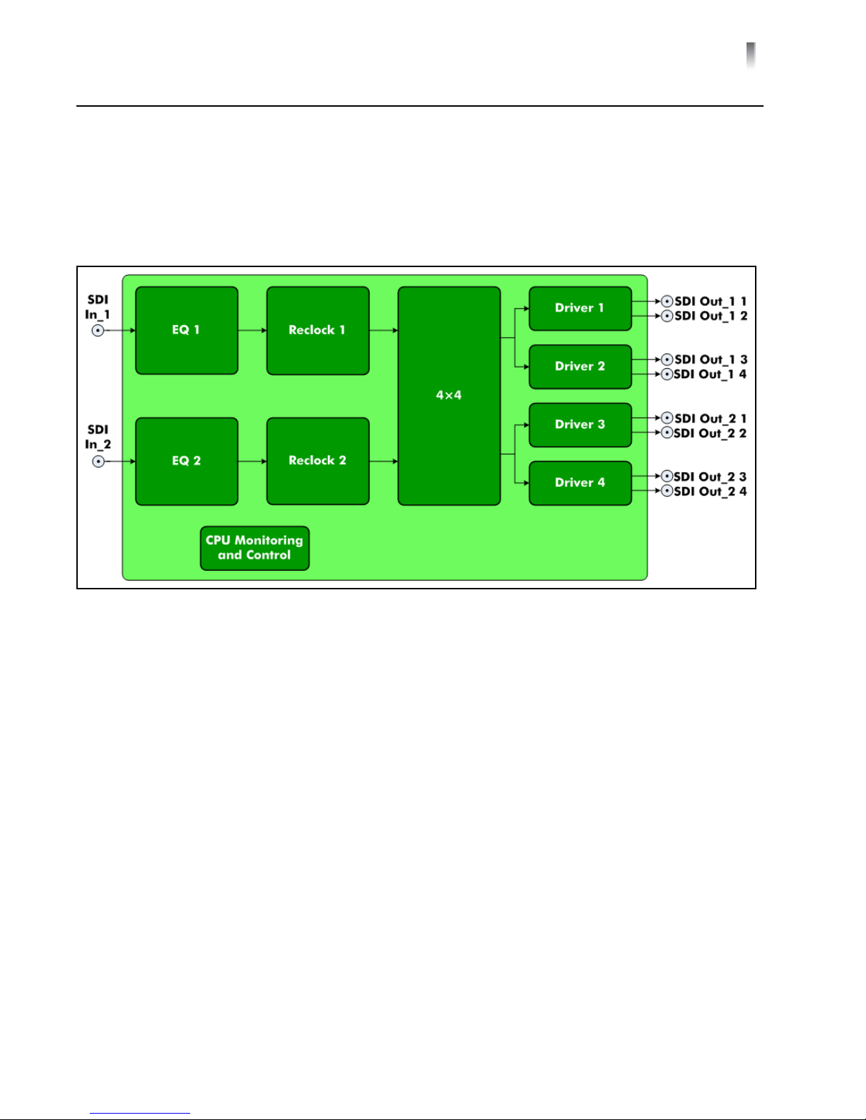
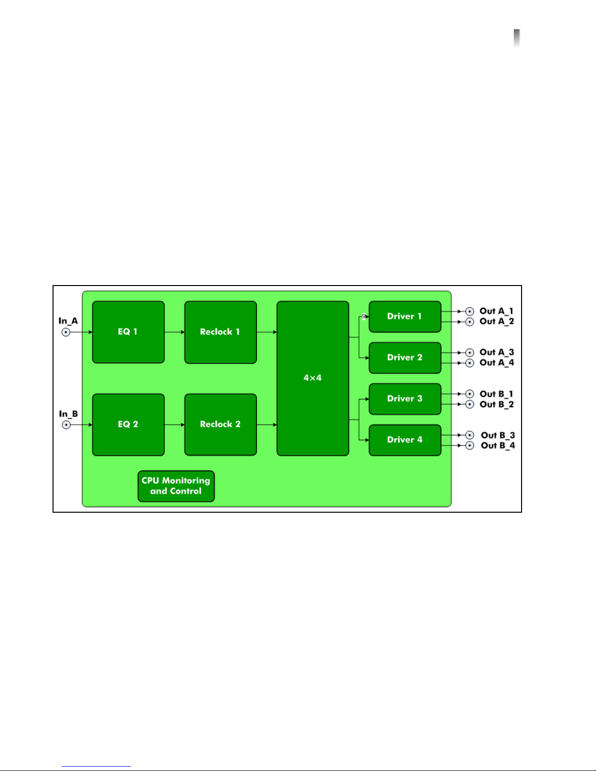
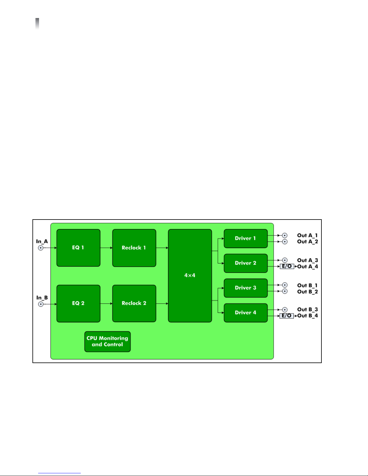
The main features for the DA-DHR6804+D are listed below. Figure 1-1 shows a
basic signal flow diagram for this distribution amplifier module.
Figure 1-1 DA-DHR6804+D Signal Flow Diagram
Operates with standard dual slot distribution amplifier back module (see
page 14)
Passes signals at data rates from 5 Mb/s to 3 Gb/s
Four selectable channel configurations:
1×8_ACO: 1 input to 8 outputs with auto changeover
The signal on SDI In_1 is distributed to 8 outputs. If the signal at SDI In_1
disappears, the outputs are switched to SDI In_2 (if a signal at SDI In_2 is
detected).
When the signal reappears at SDI In_1, the outputs are switched back to
SDI In_1 from SDI In_2 automatically.
1×8_ In_1: SDI In_1 to 8 outputs
1×8_ In_2: SDI In_2 to 8 outputs
2_1×4: 2 independent 1×4
SDI In_1 to SDI Out_1, 1-4
SDI In_2 to SDI Out_2, 1-4
Input signal presence detect and report
Automatic input cable equalization
Selectable + 6dB gain to use external passive 75 2×1 splitter (via CCS only)
Copyright © 2010, Harris Corporation
Page 18
4
Chapter 1
Introduction
Selectable input EQ bypass
Reclockable for 270 Mb/s, 1.485 Gb/s, or 2.97 Gb/s SMPTE and DVB-ASI
signals
Three selectable reclocking modes (automatic, manual, enforce bypass)
Automatic bypassing reclock stage if not relockable
Reclock status and data rate report
Automatic slew rate control for output signal
Automatic power saving if no input signal or no termination on the output
BNC
Local and remote control
Module hot swappable
DA-DH6804+D
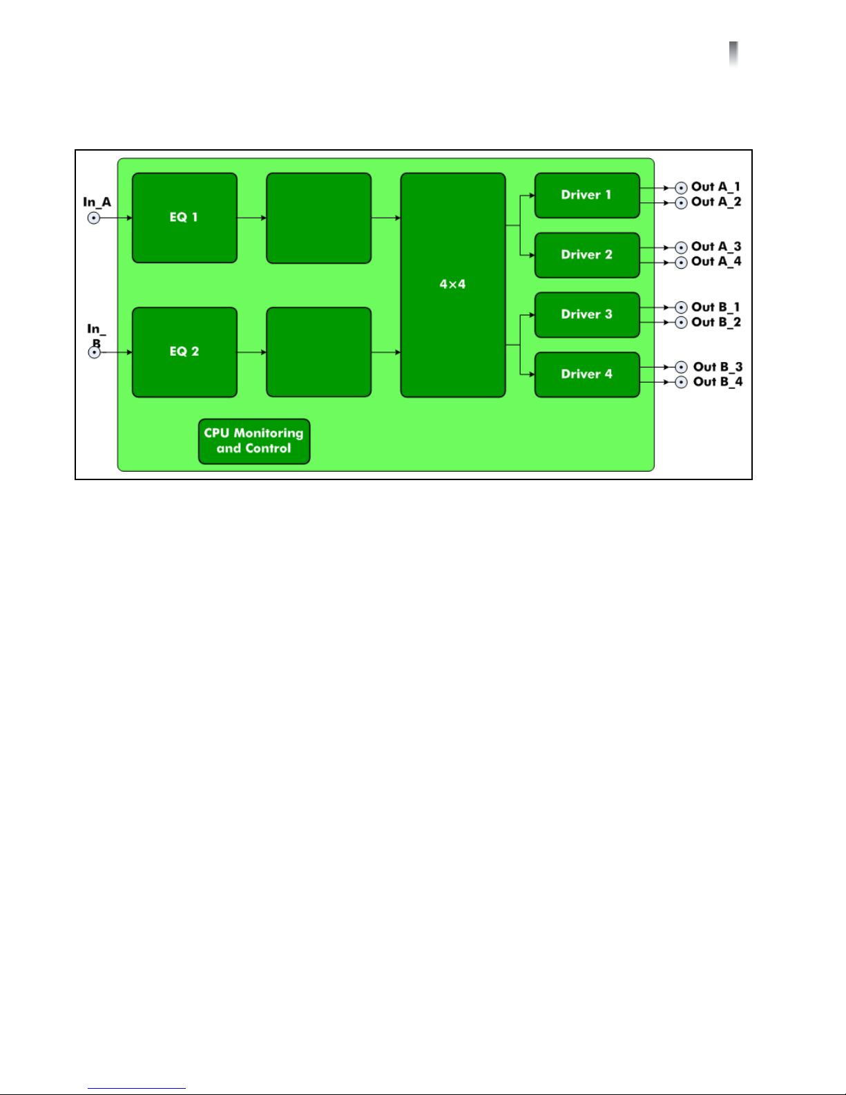
The main features for the DA-DH6804+D are listed below. Figure 1-2 shows a
basic signal flow diagram for this distribution amplifier module.
Figure 1-2 DA-DH6804+D Signal Flow Diagram
Operates with standard dual slot distribution amplifier back module (see
Passes signals at data rates from 5 Mb/s to 3 Gb/s
Four selectable channel configurations:
Copyright © 2010, Harris Corporation
page 14)
1×8_ACO: 1 input to 8 outputs with auto changeover
The signal on SDI In_1 is distributed to 8 outputs. If the signal at SDI In_1
disappears, the distribution amplifier outputs are switched to SDI In_2 (if a
signal at SDI In_2 is detected).
When the signal reappears SDI In_1, the outputs are switched back to SDI
In_1 from SDI In_2 automatically.
1×8_ In_1: SDI In_1 to 8 outputs
1×8_ In_2: SDI In_2 to 8 outputs
Page 19
DA-6804+D Series
Installation and Operation Manual
2_1×4: 2 independent 1×4
SDI In_1 to SDI Out_1, 1-4
SDI In_2 to SDI Out_2, 1-4
Input signal presence detect and report
Automatic input cable equalization
Selectable +6 dB gain to use external passive 75 2×1 splitter (via CCS only)
Selectable input EQ bypass
Automatic power saving if not input signal or no termination on the output
BNC
Local and remote control
Module hot swappable
5
DA-DSR6804+D
The main features for the DA-DSR6804+D are listed below. Figure 1-3 shows a
basic signal flow diagram for this distribution amplifier module.
Figure 1-3 DA-DSR6804+D Signal Flow Diagram
Operates with standard dual slot distribution amplifier back module (see
Passes signals at data rates from 5 Mb/s to 540 Mb/s
Four selectable channel configurations:
page 14)
1×8_ACO: 1 input to 8 outputs with auto changeover
The signal on SDI In_1 is distributed to 8 outputs. If the signal at SDI In_1
disappears, the outputs are switched to SDI In_2 (if a signal at SDI In_2 is
detected).
When the signal reappears SDI In_1, the outputs are automatically
switched back to SDI In_1 from SDI In_2.
1×8_ In_1: SDI In_1 to 8 outputs
Copyright © 2010, Harris Corporation
Page 20

6
Chapter 1
Introduction
1×8_ In_2: SDI In_2 to 8 outputs
2_1×4: 2 independent 1×4
SDI In_1 to SDI Out_1, 1-4
SDI In_2 to SDI Out_2, 1-4
Input signal presence detect and report
Automatic input cable equalization
Selectable +6 dB gain to use external passive 75 2×1 splitter (via CCS only)
Selectable input EQ bypass
Reclockable for 270 Mb/s SMPTE and DVB-ASI signals
Three selectable reclocking modes (automatic, manual, enforce bypass)
Automatic bypassing reclock stage if not relockable
Reclock status and data rate report
Automatic slew rate control for output signal
Automatic power saving if not input signal or no termination on the output
BNC
Local and remote control
Module hot swappable
Copyright © 2010, Harris Corporation
Page 21
DA-6804+D Series
Installation and Operation Manual
7
DA-DS6804+D
The main features for the DA-DS6804+D are listed below. Figure 1-4 shows a
basic signal flow diagram for this distribution amplifier module.
Figure 1-4 DA-DS6804+D Signal Flow Diagram
Operates with standard dual slot distribution amplifier back module (see
page 14)
Passes signals at data rates from 5 Mb/s to 540 Mb/s
Four selectable channel configurations:
1×8_ACO: 1 input to 8 outputs with auto changeover
The signal on SDI In_1 is distributed to 8 outputs. If the signal at SDI In_1
disappears, the outputs are switched to SDI In_2 (if a signal at SDI In_2 is
detected).
When the signal reappears on SDI In_1, the outputs are automatically
switched back to SDI In_1 from SDI In_2.
1×8_ In_1: SDI_ In_1 to 8 outputs
1×8_ In_2: SDI_ In_2 to 8 outputs
2_1×4: 2 independent 1x4
SDI In_1 to SDI Out_1, 1-4
SDI In_2 to SDI Out_2, 1-4
Input signal presence detect and report
Automatic input cable equalization
Selectable +6 dB gain to use external passive 75 2×1 splitter (via CCS only)
Selectable input EQ bypass
Automatic power saving if not input signal or no termination on the output
BNC
Local and remote control
Module hot swappable
Copyright © 2010, Harris Corporation
Page 22
8
Chapter 1
Introduction
DA-HRO6804+D
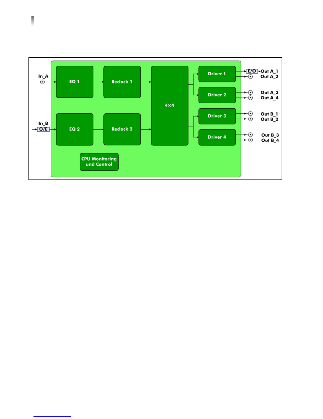
The main features for the DA-HRO6804+D are listed below. Figure 1-5 shows a
basic signal flow diagram for this distribution amplifier module.
Figure 1-5 DA-HRO6804+D Signal Flow Diagram
Operates with dual slot, RT optical distribution amplifier back module (see
page 14)
Passes signals at data rates from 5 Mb/s to 3 Gb/s
Three selectable channel configurations:
1×8_ACO: 1 electrical input to 1 optical output and 7 electrical outputs
with auto changeover
The Electrical signal on SDI In_1 is distributed to 1 optical output and 7
electrical outputs. If the electrical signal at SDI In_1 disappears, the
outputs are switched to Optical input at SDI In_2 (if an Optical signal at
SDI In_2 is detected). When the Electrical signal reappears on SDI In_1, the
outputs are automatically switched back to SDI In_1 from SDI In_2.
1×8_ In_1: 1 electrical input (In_A) to 1 optical output and 7 electrical
outputs
1×8_ In_2: 1 optical input (In_B) to 1 optical output and 7 electrical
outputs
Input signal presence detect and report
Optical input status for optical input (by CCS)
Automatic input cable equalization for electrical input
Selectable +6 dB gain to use external passive 75 2×1 splitter (via CCS only)
for electrical input
Selectable input EQ bypass for electrical input
Reclockable for 270 Mb/s, 1.485 Gb/s, or 2.97 Gb/s SMPTE and DVB-ASI
signals
Three selectable reclocking modes (automatic, manual, enforce bypass)
Copyright © 2010, Harris Corporation
Page 23
DA-6804+D Series
Installation and Operation Manual
Automatic bypassing reclock stage if not relockable
Reclock status and data rate report
Automatic slew rate control for electrical output signal
Optical output protection enable
Output output loss alarm
Optical status for optical output (by CCS)
Automatic power saving if not input signal or no termination on the output
BNC
Local and remote control
Module hot swappable
9
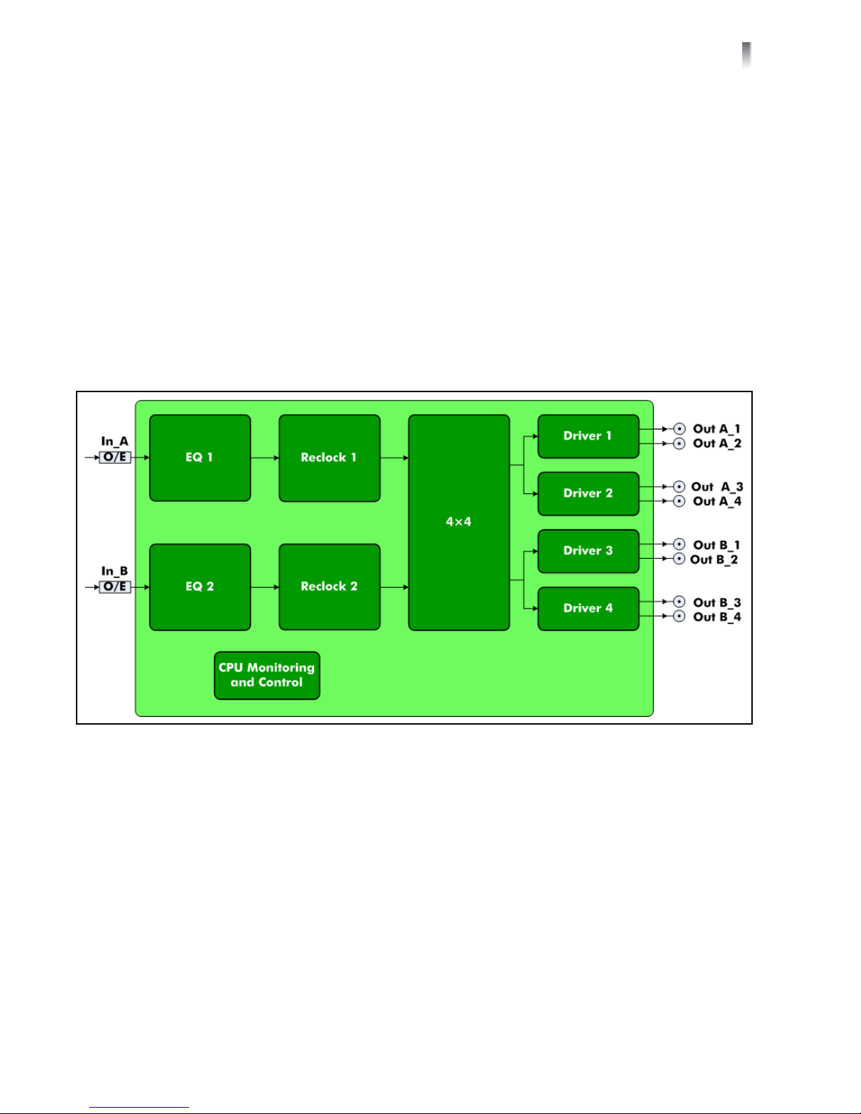
DA-DHROE6804+D
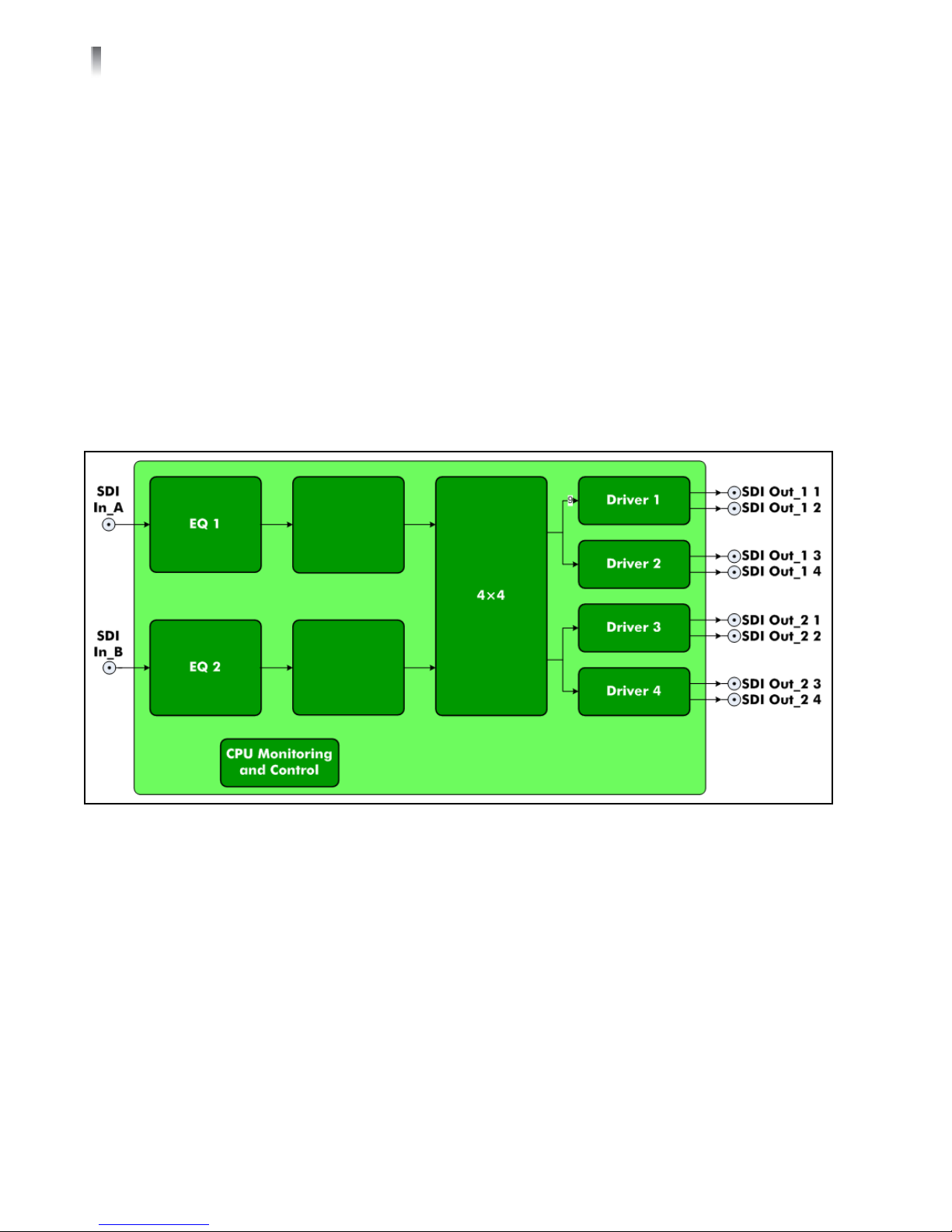
The main features for the DA-DHROE6804+D are listed below. Figure 1-6 shows a
basic signal flow diagram for this distribution amplifier module.
Figure 1-6 DA-DHROE6804+D Signal Flow Diagram
Operates with dual slot, RR optical distribution amplifier back module (see
Passes signals at data rates from 5 Mb/s to 3 Gb/s
Four selectable channel configurations:
page 14)
1×8_ACO: 1 optical input (In_A) to 8 electrical outputs with auto
changeover
The optical signal on In_A is converted and distributed to 8 electrical
outputs. If the signal at In_A disappears, the outputs are switched to In_B
(if a signal at In_B is detected).
When the signal reappears on In_A, the outputs are automatically
switched back to In_A from In_B.
1×8_ In_1: optical In_A to 8 electrical outputs
Copyright © 2010, Harris Corporation
Page 24
10
Chapter 1
Introduction
1×8_ In_2: optical In_B to 8 electrical outputs
2_1×4: 2 independent 1×4
Optical In_A to electrical Out_A, 1-4
Optical In_B to electrical Out_B, 1-4
Input signal presence detect and report
Optical input status for optical input (by CCS)
Reclockable for 270 Mb/s, 1.485 Gb/s, or 2.97 Gb/s SMPTE and DVB-ASI
signals
Three selectable reclocking modes (automatic, manual, enforce bypass)
Automatic bypassing reclock stage if not relockable
Reclock status and data rate report
Automatic slew rate control for electrical output signal
Automatic power saving if not input signal or no termination on the output
BNC
Local and remote control
Module hot swappable
DA-DHREO6804+D
The main features for the DA-DHREO6804+D are listed below. Figure 1-7 shows a
basic signal flow diagram for this distribution amplifier module.
Figure 1-7 DA-DHREO6804+D Signal Flow Diagram
Operates with dual slot, TT optical distribution amplifier back module (see
Passes signals at data rates from 5 Mb/s to 3 Gb/s
Four selectable channel configurations:
Copyright © 2010, Harris Corporation
page 14)
Page 25

DA-6804+D Series
Installation and Operation Manual
1×8_ACO: 1 electrical input (In_A) to 6 electrical outputs and 2 optical
outputs with auto changeover
The signal on In_A is distributed to 6 electrical outputs and 2 optical
outputs. If the signal at In_A disappears, the outputs are switched to In_B
(if a signal at In_B is detected).
When the signal reappears on In_A, the outputs are automatically
switched back to In_A from In_B.
1×8_ In_1: Electrical In_A to 6 electrical outputs and 2 optical outputs
1×8_ In_2: Electrical In_B to 6 electrical outputs and 2 optical outputs
2_1×4: 2 independent 1×4
Electrical In_A to Out_A, 1 optical output and 3 electrical outputs
Electrical In_B to Out_B, 1 optical output and 3 electrical outputs
Input signal presence detect and report
Automatic input cable equalization for electrical input
Selectable +6 dB gain to use external passive 75 2×1 splitter (via CCS only)
for electrical input
Selectable input EQ bypass for electrical input
Reclockable for 270 Mb/s, 1.485 Gb/s, or 2.97 Gb/s SMPTE and DVB-ASI
signals
Three selectable reclocking modes (automatic, manual, enforce bypass)
Automatic bypassing reclock stage if not relockable
Reclock status and data rate report automatic slew rate control for electrical
outputs
Optical output protection enable
Optical output loss alarm
Optical status for optical output (by CCS)
Automatic power saving if not input signal or no termination on the output
BNC
Local and remote control
Module hot swappable
11
Copyright © 2010, Harris Corporation
Page 26

12
Chapter 1
Introduction
DA-DHROO6804+D
The main features for the DA-DHROO6804+D are listed below. Figure 1-8 shows
a basic signal flow diagram for this distribution amplifier module.
Figure 1-8 DA-DHROO6804+D Signal Flow Diagram
Operates with dual slot, 3SFP optical distribution amplifier back module (see
page 14)
Passes signals at data rates from 5 Mb/s to 3 Gb/s
Four selectable channel configurations:
1×8_ACO: 1 optical input (In_A) to 4 electrical outputs and 4 optical
outputs with auto changeover
The optical signal on In_A is distributed to 4 electrical outputs and 4
optical outputs. If the signal at In_A disappears, the outputs are switched
to In_B (if an optical signal at In_B is detected).
When the signal is reappears In_A, the outputs are automatically switched
back to In_A from In_B.
1×8_ In_1: optical In_A to four electrical outputs and four optical outputs
1×8_ In_2: optical In_B to four electrical outputs and four optical outputs
2_1×4: 2 independent 1×4
Optical In_A to OUT_A1/A2 (optical outputs) and A3/A4 (electrical
outputs)
Optical In_B to OUT_B1/B2 (optical outputs) and B3/B4 (electrical
outputs)
Input signal presence detect and report
Optical input status for optical input (by CCS)
Reclockable for 270 Mb/s, 1.485 Gb/s, or 2.97 Gb/s SMPTE and DVB-ASI
signals
Three selectable reclocking modes (automatic, manual, enforce bypass)
Automatic bypassing reclock stage if not relockable
Copyright © 2010, Harris Corporation
Page 27

DA-6804+D Series
Installation and Operation Manual
Reclock status and data rate report
Automatic slew rate control for electrical output signal
Optical output protection enable
Optical output loss alarm
Optical status for optical output (by CCS)
Automatic power saving if not input signal or no termination on the output
BNC
Local and remote control
Module hot swappable
13
Copyright © 2010, Harris Corporation
Page 28

14
Chapter 1
Introduction
Product
Views
Front Module
Back Modules
This section includes information about the front and back modules, as well as a
view of the rear of a frame with various DA-6804+D series back connector
modules installed.
Figure 1-9 DA-6804+D Series Front Module
DA-6804+D series modules can be installed with double-width back modules in
their respective host frames. (These modules cannot be installed in 6800 /7000
series frames.)
Table 1-1 Back Modules
DA-DS6804+D
DA-DSR6804+D
DA-DH6804+D
DA-DHR6804+D
Table 1-1 show the back connector modules used with corresponding front
modules when installed in the host frame.
DA-HRO6804+D DA-DHROE6804+D DA-DHREO6804+D DA-DHROO6804+D
Copyright © 2010, Harris Corporation
Page 29

DA-6804+D Series
Installation and Operation Manual
15
Rear View
Maximum 6800+
Frame Power
Ratings
Figure 1-10 shows a rear view of the DA-6804+D Series fully-filled frame. The
frame holds 10 modules (each front module and its corresponding back module
occupies 2 slots in a frame).
Figure 1-10 Frame Rear View
Power consumption information is listed in Chapter 4, Specifications on page 52.
Table 1-2 describes the maximum allowable power ratings for 6800+ frames.
Note the given maximums before installing any 6800+ modules in your frame.
DA-6804+D series modules cannot be installed in 6800 / 7000 series frames.
Table 1-2 Maximum Power Ratings for 6800+ Frames
6800+ Frame Type
FR6802+XF
(frame with AC power
supply)
FR6802+XF48
(frame with DC power
supply)
FR6802+QXF
(frame with AC or DC
power supply)
FR6822+
(frame with AC or DC
power supply)
Max. Frame
Power
Dissipation
120 W 20 6 W
105 W 20 5.25 W
120 W 20 6 W
120 W 20 6 W
Number of
Usable Slots
Max. Power
Dissipation
Per Slot
Copyright © 2010, Harris Corporation
Page 30

16
Chapter 1
Introduction
Copyright © 2010, Harris Corporation
Page 31

2
17
Installation
CAUTION: Before installing this product, read the 6800+ Series
Safety Instructions and Standards manual shipped with every frame
installation and operation manual, or downloadable from our
website. This safety manual contains important information about
the safe installation and operation of 6800+ series products.
Before you install DA-6804+D series modules, perform the following:
Remove the anti-static shipping pouch, if present, and all other packaging
material.
Retain the original packaging materials for possible re-use.
Confirm receipt of all items on the packing list. See Checking the Packing
List on page 18.
Check the equipment for any visible damage that may have occurred during
transit.
Contact your Customer Service representative if parts are missing or damaged.
See Unpacking/Shipping Information on page ix for information about
returning a product for servicing.
Copyright © 2010, Harris Corporation
Page 32

18
Chapter 2
Installation
Checking the
Packing List
Table 2-1 shows the items that are part of your DA-6804+D series module
package. If any of these items are missing from your shipment, contact your
Customer Service representative.
Table 2-1 DA-6804+D Series Packing List
Ordered Product Content Description
DA-DHR6804+D: 3G/HD/SD/ASI Dual Channel Distribution Amplifier
with Reclocking
DA-DHR6804+ One DA-DHR6804+ front module
One DA-6804+ Series Installation and Operation
Manual
DA-DHR6804+D One DA-DHR6804+ front module
One standard double-slot BNC back connector
module
One DA-6804+ Series Installation and Operation
Manual
DA-DH6804+D 3G/HD/SD/ASI Dual Channel Distribution Amplifier
DA-DH6804+ One DA-DH6804+ front module
One DA-6804+ Series Installation and Operation
Manual
DA-DH6804+D One DA-DH6804+ front module
One standard double-slot BNC back connector
module
One DA-6804+ Series Installation and Operation
Manual
DA-DSR6804+D SD/ASI Dual Channel Distribution Amplifier with
Reclocking
DA-DSR6804+ One DA-DSR6804+ front module
One DA-6804+ Series Installation and Operation
Manual
DA-DSR6804+D One DA-DSR6804+ front module
One standard double-slot BNC back connector
module
One DA-6804+ Series Installation and Operation
Manual
DA-DS6804+D SD/ASI Dual Channel Distribution Amplifier with
Reclocking
DA-DS6804+ One DA-DS6804+ front module
One DA-6804+ Series Installation and Operation
Manual
DA-DS6804+D One DA-DS6804+ front module
One standard double-slot BNC back connector
module
One DA-6804+ Series
Manual
Installation and Operation
Copyright © 2010, Harris Corporation
Page 33

DA-6804+D Series
Installation and Operation Manual
Table 2-1 DA-6804+D Series Packing List (Continued)
Ordered Product Content Description
DA-HRO6804+D 3G/HD/SD Optical and Electrical Distribution
Amplifier
DA-HRO6804+D One DA-DHR6804+ front module
One RT optical distribution amplifier back
connector module
One DA-6804+ Series Installation and Operation
Manual
DA-DHROE6804+D 3G/HD/SD/ASI Dual Channel Optical to Electrical
Distribution Amplifier
DA-DHROE6804+D One DA-DHR6804+ front module
One RR optical distribution amplifier back
connector module
One DA-6804+ Series Installation and Operation
Manual
DA-DHREO6804+D 3G/HD/SD/ASI Dual Channel Electrical to Optical
Distribution Amplifier
19
DA-DHREO6804+D One DA-DHR6804+ front module
One TT optical distribution amplifier back
connector module
One DA-6804+ Series Installation and Operation
Manual
DA-DHROO6804+D 3G/HD/SD/ASI Dual Channel Electrical to Optical
Distribution Amplifier
DA-DHROO6804+D
One DA-DHR6804+ front module
One 3SFP optical distribution amplifier back
connector module
One DA-6804+ Series Installation and Operation
Manual
Copyright © 2010, Harris Corporation
Page 34

20
Chapter 2
Installation
Setup
Procedures
Setting Up a
Frame
DA-6804+D series frames, back connectors, and front modules require different
setup procedures before the modules can be installed in the frame.
Frame setup consists of installing a frame into its rack, and then connecting to a
power and/or Ethernet source. See the appropriate frame installation and
operation manual for details on installing and operating the frame and its
components.
If the frame does not have CCS control, plug a power cord (A) to the back of the
frame as shown in Figure 2-1. Plug the other end of the power cord into an
electrical outlet.
Figure 2-1 Connection for Non-CCS Control
Copyright © 2010, Harris Corporation
Page 35

DA-6804+D Series
Installation and Operation Manual
If the frame uses CCS control, plug the power cord (A) and the Ethernet connector
cable (B) to the back of the frame, as shown in Figure 2-2. Plug the other end of
the power cord into an electrical outlet. Plug the other end of the Ethernet
connector to a PC that has Harris CCS software installed.
21
Setting Up Back
Connector
Modules
Figure 2-2 Connection for CCS Control
Back module setup consists of plugging in coaxial cables (A) and fiber optical
cables (B), as shown in Figure 2-3. Apply a 75 coaxial cable to the BNC jacks and
LC single mode fiber optical cables, as appropriate, to installed back modules. The
other ends of the cables should be connected to a system’s other devices.
Figure 2-3 Plugging in Coaxial and Fiber Optical Cables
CAUTION: Take special care when attaching fiber optical cables. See
page 21 for more information.
Copyright © 2010, Harris Corporation
Page 36

22
Chapter 2
Installation
Setting Up Front
Modules
Setting Up J1 and J2
Jumpers
Front module setup consists of setting the jumpers for the DA-6804+D series
modules. Three jumpers that need to be set: J1 and J2 are used for reclockers, and
J3 is designed for channel configuration and enabling remote control.
Figure 2-4 shows the location of the J1, J2, and J3 jumpers.
Figure 2-4 Jumper Locations
J1 and J2 are used to locally set the reclocker working mode. J1 is used for
channel 1 and J2 for is used for channel 2. The reclocker remains in AUTO mode if
no shunt is on any position of the jumper.
Table 2-2 J1 and J2 Jumper Settings
Jumper
Selection
Pin
Setting
Label Description
J1/J2 1/2 AUTO_1/2 Input signal locked at one of these
data rates:
2.97 Gb/s
1.485 Gb/s
270 Mb/s
If not relockable, signal automatically
bypasses reclocker
J1/J2 3/4 3.0G_1/2 Input signal locked at 2.97 Gb/s*;if
not relockable, signal automatically
bypasses reclocker
J1/J2 5/6 HD_1/2 Input signal locked at 1.485 Gb/s*;if
not relockable, signal automatically
bypasses reclocker
J1/J2 7/8 SD_1/2 Input locked at 270 Mb/s; if not
relockable, signal automatically
bypasses reclocker
J1/J2 9/10 BYPASS_1/2 Enforces signal bypass reclocker
*
Not used with DA-DSR6804+
Copyright © 2010, Harris Corporation
Page 37

DA-6804+D Series
Installation and Operation Manual
23
Setting Up J3
Jumpers
The J3 jumper controls the control modes available for DA-6804+D series modules.
Local control for channel configuration
Remote control enable
Table 2-3 J3 Jumper Settings
Jumper
Selection
Pin
Setting
Label Description
J3 1/2 1×8_ACO Locally configures distribution
amplifier as single channel (1×8) with
ACO
J3 3/4 1×8_IN1 Locally configures distribution
amplifier as single channel (1×8);
input is from IN1
J3 5/6 1×8_IN2 Locally configures distribution
amplifier as single channel (1×8);
input is from IN2
J3 7/8 2_1×4 Locally configures distribution
amplifier as dual channel (2-1×4)
J3 11/12 REMOTE Enables remote control via CCS; J3
pins 1-8 are not functional
Copyright © 2010, Harris Corporation
Page 38

24
Chapter 2
Installation
Installing and
Removing
Modules
Back Module
Installation
The DA-6804+D series front modules have corresponding back modules that are
installed in the host frame. See page 24 for details on installing back modules.
These modules cannot be installed in 6800/7000 series frames.
The DA-6804+D series back modules have specialized installation procedures. If
installing both front and back modules, ensure that the back module is installed
first before plugging in the front module.
When removing both the front and back modules, ensure that the front
module is unplugged from the frame first, before removing the back module.
See the appropriate frame installation and operation manual for details on
installing and operating the frame and its components.
See the 6800+ Safety Instructions and Standards Manual for important
information about safely installing your module.
Once you have installed the modules, you can connect them to the appropriate
input and outputs.
SFPs on DA-6804+D series back modules have plastic caps that protect the fragile
laser connections from dust (see Figure 2-5 on page 25). You must remove these
protective covers before you attach the fiber cables.
Figure 2-5 on page 25 shows a typical fiber optical back module. Your module’s
appearance may differ slightly from the one shown; however, the protective covers
are positioned identically and must be removed according to the instructions
provided. The installation instructions that follow will prompt you as to when you
should remove the protective covers.
In addition, all of the LC connections of the fiber optical cables must be inspected
and cleaned before they are assembled. Carefully follow the inspection and
cleaning steps described in the next pages. Additional safety information begins on
Laser Safety Guidelines on page 53.
Copyright © 2010, Harris Corporation
Page 39

DA-6804+D Series
Installation and Operation Manual
25
Front Module
Installation
Figure 2-5 Protective Covers for Laser Connectors
1 Remove a blank back plate from the frame. Do not discard the blank back
plates. They may be needed for future configurations.
CAUTION: Microscopic dust or other contaminants can seriously
impair or disable a fiber optic network. Observe strict cleaning
procedures. Do not touch the end of the fiber.
2 If it is already installed, remove the front module from the slot.
3 Install the new back module by inserting the bottom lip into the required
frame slot, and then screwing it into place.
4 Follow the fiber cable inspection and cleaning procedure that begins on
page 59.
5 Insert the front module into the slot holding the corresponding back module.
6 Attach the fiber cable and/or electrical cables to the back module (see Setting
Up Back Connector Modules on page 21).
Front modules require no specialized installation procedures other than those
described in Setting Up Front Modules on page 22. If installing both front and
back modules, ensure that the back module is installed first before plugging in the
front module.
Removing Modules
These modules require no specialized removal procedures. If installing both front
and back modules, ensure that the front module is removed first.
Copyright © 2010, Harris Corporation
Page 40

26
Chapter 2
Installation
Copyright © 2010, Harris Corporation
Page 41

3
27
Operation
When a frame, back modules, and the front module are set up, plug the front
module into the frame; connect the input and output cables to BNCs on back
module and/or LC fiber optional cables to SFPs; and turn on the power supply of
the frame. After approximately three seconds, the distribution amplifier should
operate properly. Usually there is no need for other operational changes.
Without a CCS remote control system, DA-6804+D series distribution amplifiers
are fully functional in FR6802+ frames. With an installed CCS system (including
6800+ETH module in the FR6802+ frame), distribution amplifier operation can be
monitored and configured on the remote computer display. The J3 jumper must be
set to REMOTE (see Table 2-3 on page 23). If the J3 jumper is not set to this
setting, the distribution amplifier can be remotely monitored only, and remote
configuration is not possible.
Copyright © 2010, Harris Corporation
Page 42

28
Chapter 3
Operation
LED Displays
LEDs on the front edge of the front module report the operating status when
power is ON and signal is applied. The location of the system status (A) and signal
condition (B) LEDs are shown in Figure 3-1. The meaning of the system status LED
color sequence is described in Table 3-1. The meanings for the signal condition
LEDs are described in Table 3-2.
Figure 3-1 LED Locations
System Status
Indicators
Signal Condition
Indicators
Table 3-1 System Status Indicator LED Descriptions
LED Color Sequence Meaning
Off There is no power to the module; the module is not
operational
Red There is an alarm condition
Green There is power to the module; the module is
operating properly
Each 6800+ module has a number of LEDs assigned to indicate varying states /
functions. These functions are listed in Table 3-2.
Table 3-2 Signal Condition LED Descriptions
Name Color Function
PRES Green Input signal is present
Off Input signal is absent
LOCK Green Input signal is locked
Off Input signal is unlocked and appears on the
outputs
Copyright © 2010, Harris Corporation
Page 43

DA-6804+D Series
Installation and Operation Manual
Table 3-2 Signal Condition LED Descriptions (Continued)
Name Color Function
270 Green Input signal is reclocked at 270 Mb/s
Off Input signal is not reclocked
1.5G Green Input signal is reclocked at 1.485 Gb/s
Off Input signal is not reclocked
3.0G Green Input signal is reclocked at 2.97 Gb/s
Off Input signal is not reclocked
29
Alarms
If an alarm is triggered within a module, the module status LED turns red and the
alarm light on the front of the frame lights red.
Figure 3-2 Alarm Indicator, System Status LED
Figure 3-3 Alarm Indicator, Frame Front
Copyright © 2010, Harris Corporation
Page 44

30
Chapter 3
Operation
Alarms are usually logged and monitored within the available software control
applications. See the appropriate software control user manual or online help for
more information.
Table 3-3 Alarm Definitions
Alarm Name Alarm Description Alarm Level
Ch. 1 loss of input Indicates input signal for channel 1 is lost
or absent
Ch. 2 loss of input Indicates input signal for channel 2 is lost
or absent
Ch. 1 loss of lock Indicates signal for channel 1 is not
locked
Ch. 2 loss of lock Indicates signal for channel 2 is not
locked
Ch.1a Tx Fault Indicates SFP transmitter fault on
channel 1a
Ch.1b Tx Fault Indicates SFP transmitter fault on
channel 1b
Ch.2a Tx Fault Indicates SFP transmitter fault on
channel 2a
Ch.2b Tx Fault Indicates SFP transmitter fault on
channel 2b
Major
Major
Major
Major
Major
Major
Major
Major
Copyright © 2010, Harris Corporation
Page 45

DA-6804+D Series
Installation and Operation Manual
31
Web-Enabled
Display and
Control
NOTE: To enable web-based display and control, make sure that you have
set up the frame for CCS control, as described in Setting Up a Frame on
page 20. You must also have an 6800+ETH Ethernet connection module
installed.
To access the web-enabled display, open a web browser and enter the IP address of
the frame in the Address field, and then click Enter at the 6800+ Control
Interface display. A view of the frame modules components is displayed on
screen.
Figure 3-4 Web-Enabled Control Display
A tree view of the frame and its contents is displayed at the left of the screen. Click
the + button (or click on the component name) to expand the tree view.
Information corresponding to the selection is displayed in the control pane to the
right of the tree view.
Click the - button to collapse the tree view.
When you select the frame and slot for a distribution amplifier module location,
the software displays the item list in the tree view and the item values on the
control pane, as shown in Figure 3-5. Some parameters are adjustable if the J3
jumper is set to REMOTE.
Copyright © 2010, Harris Corporation
Page 46

32
Chapter 3
Operation
Figure 3-5 Parameter View for Web-Enabled Display
In the value display boxes on the pane, the value of read-only parameter is
displayed as grey ground with black characters and you cannot change it. The
adjustable parameter value is displayed as white ground with black characters. The
adjustable parameter boxes should be turned to grey if the J3 jumper is not set on
the REMOTE pins.
Copyright © 2010, Harris Corporation
Page 47

DA-6804+D Series
Installation and Operation Manual
33
CCS Naviga-
tor Display
and Control
NOTE: This section presupposes that you have a working knowledge of
CCS Navigator and have used the software’s other capabilities. If not,
please refer to the pertinent software application user manual to
familiarize yourself with its functions before you continue.
When viewing the DA-6804+D series in Navigator control mode, a control pane is
displayed on screen of the computer monitor. When you select the frame and slot
for a distribution amplifier module location, the software displays the item values
on the control pane, as shown in Figure 3-6. Some parameters are adjustable if
the J3 jumper is set to REMOTE.
Figure 3-6 CCS Navigator Control Display
In the value display boxes on the pane, the value of read-only parameter is
displayed as black ground with green characters. The adjustable parameter value is
displayed as white ground with black characters. The adjustable parameter boxes
should be turned to grey if the J3 jumper is not set to REMOTE.
Copyright © 2010, Harris Corporation
Page 48

34
Chapter 3
Operation
Operating
Notes
Setting
Locally
Controlled
Parameters
When you set the control parameters on DA-6804+D series distribution amplifiers,
observe the following:
If you make changes to certain parameters, other related parameters may also
be affected.
When you change a parameter, the effect is immediate. However, the module
requires up to 30 seconds to save the latest change. After 30 seconds, the new
settings are saved and will be restored if the module loses power and must be
restarted.
In the local control operation mode, all of the settings’ data status information
appears on the CCS control software application control screen; however, you
cannot change any setting in this mode via the CCS control software application.
(To control the operation mode via the CCS control software application, set the J3
jumper to the REMOTE.)
Reclocking mode and control mode parameters are available for local control.
The J1 and J2 jumpers are used to determine reclocking mode. Table 2-2 on
page 22 describes parameters that are accessible locally.
The J3 jumper is used to determine control mode. Table 2-3 on page 23 describes
parameters that are accessible locally.
Setting
Remotely
Controlled
Parameters
Copyright © 2010, Harris Corporation
In the remote control operation mode, all of the settings’ data status information
appears on the CCS control software application control screen, and you can
change settings in this mode via the CCS control software application. (To control
the operation mode via the CCS control software application, set the J3 jumper to
the REMOTE.) Figure 3-4 on page 31 shows a web-enabled control pane and
Figure 3-6 on page 33 shows a Navigator control pane displaying the parameters
for a DA-DHROO6804+D module. Table 3-8 describes parameters that are
accessible remotely.
See your CCS control software application manual or online help for more
information on setting and monitoring these parameters remotely.
Page 49

DA-6804+D Series
Installation and Operation Manual
Table 3-4 DA-DHR6804+D/DA-DH6804+D/DA-DSR6804+D/DA-DS6804+D
Remotely Controlled Parameters
Bold text = Default setting [RO] = Read only/feedback
Path Parameter Range Description
Processing Serial Number [RO] String Serial number for the module
License Key String License key number for the module
Other Output Config.
Ch.1 Signal Present [RO]
Ch.2 Signal Present [RO]
Ch.1 Loss of Input Alarm
Ch.2 Loss of Input Alarm
Current Input [RO]
NOTE: Only valid in 1×8
Ch.1 1×8 with ACO
Ch.1 1×8
Ch.2 1×8
2×4
No
Yes
No
Yes
Disabled
Enabled
Disabled
Enabled
N/A
Ch. 1
Ch. 2
Selects module output configuration
as dual 1×4 or 1×8, 1 input routed to
all outputs; or 1×8 with input 2 routed
to all outputs
Indicates if the input signal for
channel 1 is present or not
Indicates if the input signal for
channel 2 is present or not
Enables or disables the Loss of Input
alarm for channel 1
Enables or disables the Loss of Input
alarm for channel 2
Indicates if the input signal is channel
1 or channel 2
with ACO mode output
configuration
Ch. 1 Slew Rate
SD
HD
Auto
Controls output/rise fall time for
channel 1
SD – Output Rise Fall time complies
with SMPTE 259M
HD – Output Rise Fall time complies
with SMPTE 424M /292M
Auto – Automatically selects proper
rise fall time based on incoming
signal
Ch. 2 Slew Rate
SD
HD
Auto
Controls output/rise fall time for
channel 2
SD – Output Rise Fall time complies
with SMPTE 259M
HD – Output Rise Fall time complies
with SMPTE 424M /292M
Auto – Automatically selects proper
rise fall time based on incoming
signal
35
Parameter Hysteresis 0.1 to 0.5 seconds Value used to determine how long a
condition (that is, signal presence)
must be asserted before it is reported
to the control system
Copyright © 2010, Harris Corporation
Page 50

Chapter 3
36
Operation
Table 3-4 DA-DHR6804+D/DA-DH6804+D/DA-DSR6804+D/DA-DS6804+D
Remotely Controlled Parameters (Continued)
Bold text = Default setting [RO] = Read only/feedback
Path Parameter Range Description
Green Mode
Out 1A Cable Fault [RO]
Out 1B Cable Fault [RO]
Out 1C Cable Fault [RO]
Out 1D Cable Fault [RO]
Out 2A Cable Fault [RO]
Out 2B Cable Fault [RO]
Out 2C Cable Fault [RO]
Out 2D Cable Fault [RO]
Ch.1 Data Rate [RO]
Ch.2 Data Rate [RO]
Ch. 1 Re-Clocking Mode
NOTE: Only valid with
DA-DHRO6804+ and
DA-DSR6804+D modules
Ch. 2 Re-Clocking Mode
NOTE: Only valid with
DA-DHRO6804+ and
DA-DSR6804+D modules
Ch1 Loss of Lock Alarm
Enabled
Disabled
Yes
No
Yes
No
Yes
No
Yes
No
Yes
No
Yes
No
Yes
No
Yes
No
Unknown
270 Mb/s
Bypass
HD
3G
Unknown
270 Mb/s
Bypass
HD
3G
Auto
270 Mb/s
Bypass
HD
3G
Auto
270 Mb/s
Bypass
HD
3G
Disabled
Enabled
Enables or disables the use of the
power-saving (“green”) mode
Reports loss of signal or termination
fault for the corresponding output
Reports loss of signal or termination
fault for the corresponding output
Reports loss of signal or termination
fault for the corresponding output
Reports loss of signal or termination
fault for the corresponding output
Reports loss of signal or termination
fault for the corresponding output
Reports loss of signal or termination
fault for the corresponding output
Reports loss of signal or termination
fault for the corresponding output
Reports loss of signal or termination
fault for the corresponding output
Displays locked data rate for channel 1
Displays locked data rate for channel 2
Selects the reclock rate for channel 1
input
Selects the reclock rate for channel 2
input
Enables or disables Loss of Lock alarm
on channel 1 (Loss of Lock alarm
indicates the signal is not locked)
Copyright © 2010, Harris Corporation
Page 51

DA-6804+D Series
Installation and Operation Manual
Table 3-4 DA-DHR6804+D/DA-DH6804+D/DA-DSR6804+D/DA-DS6804+D
Remotely Controlled Parameters (Continued)
Bold text = Default setting [RO] = Read only/feedback
Path Parameter Range Description
Ch2 Loss of Lock Alarm
Disabled
Enabled
Enables or disables Loss of Lock alarm
on channel 2 (Loss of Lock alarm
indicates the signal is not locked)
Table 3-5 DA-HRO6804+ Remotely Controlled Parameters
Bold text = Default setting [RO] = Read only/feedback
Path Parameter Range Description
Processing Serial Number [RO] String Serial number for the module
License Key String License key number for the module
Other Output Config.
Ch.1 Signal Present [RO]
Ch.2 Signal Present [RO]
Ch.1 Loss of Input Alarm
Ch.2 Loss of Input Alarm
Current Input [RO]
NOTE: Only valid in 1×8
Ch.1 1×8 with ACO
Ch.1 1×8
Ch.2 1×8
2×4
No
Yes
No
Yes
Disabled
Enabled
Disabled
Enabled
N/A
Ch. 1
Ch. 2
Selects module output configuration
as dual 1×4 or 1×8, 1 input routed to
all outputs; or 1×8 with input 2 routed
to all outputs
Indicates if the input signal for
channel 1 is present or not
Indicates if the input signal for
channel 2 is present or not
Enables or disables the Loss of Input
alarm for channel 1
Enables or disables the Loss of Input
alarm for channel 2
Indicates if the input signal is channel
1 or channel 2
with ACO mode output
configuration
Ch. 1 Slew Rate
SD
HD
Auto
Controls output/rise fall time for
channel 1
SD – Output Rise Fall time complies
with SMPTE 259M
HD – Output Rise Fall time complies
with SMPTE 424M /292M
Auto – Automatically selects proper
rise fall time based on incoming
signal
37
Copyright © 2010, Harris Corporation
Page 52

Chapter 3
38
Operation
Table 3-5 DA-HRO6804+ Remotely Controlled Parameters (Continued)
Bold text = Default setting [RO] = Read only/feedback
Path Parameter Range Description
Ch. 2 Slew Rate
SD
HD
Auto
Controls output/rise fall time for
channel 2
SD – Output Rise Fall time complies
with SMPTE 259M
HD – Output Rise Fall time complies
with SMPTE 424M /292M
Auto – Automatically selects proper
rise fall time based on incoming
signal
Parameter Hysteresis 0.1 second to 0.5 seconds Value used to determine how long a
condition (that is, signal presence)
must be asserted before it is reported
to the control system
Green Mode
Out 1A Cable Fault [RO]
Out 1B Cable Fault [RO]
Out 1C Cable Fault [RO]
Out 1D Cable Fault [RO]
Out 2A Cable Fault [RO]
Out 2B Cable Fault [RO]
Out 2C Cable Fault [RO]
Out 2D Cable Fault [RO]
Ch.1 Data Rate [RO]
Ch.2 Data Rate [RO]
Enabled
Disabled
Yes
No
Yes
No
Yes
No
Yes
No
Yes
No
Yes
No
Yes
No
Yes
No
Unknown
270 Mb/s
Bypass
HD
3G
Unknown
270 Mb/s
Bypass
HD
3G
Enables or disables the use of the
power-saving (“green”) mode
Reports loss of signal or termination
fault for the corresponding output
Reports loss of signal or termination
fault for the corresponding output
Reports loss of signal or termination
fault for the corresponding output
Reports loss of signal or termination
fault for the corresponding output
Reports loss of signal or termination
fault for the corresponding output
Reports loss of signal or termination
fault for the corresponding output
Reports loss of signal or termination
fault for the corresponding output
Reports loss of signal or termination
fault for the corresponding output
Displays locked data rate for channel 1
Displays locked data rate for channel 2
Copyright © 2010, Harris Corporation
Page 53

Installation and Operation Manual
Table 3-5 DA-HRO6804+ Remotely Controlled Parameters (Continued)
Bold text = Default setting [RO] = Read only/feedback
Path Parameter Range Description
Ch. 1 Re-Clocking Mode
Ch. 2 Re-Clocking Mode
Ch1 Loss of Lock Alarm
Auto
270 Mb/s
Bypass
HD
3G
Auto
270 Mb/s
Bypass
HD
3G
Disabled
Enabled
Selects the reclock rate for channel 1
input
Selects the reclock rate for channel 2
input
Enables or disables the Loss of Lock
alarm on channel 1 (the Loss of Lock
alarm indicates the signal is not
locked)
Ch2 Loss of Lock Alarm
Disabled
Enabled
Enables or disables the Loss of Lock
alarm on channel 2 (the Loss of Lock
alarm indicates the signal is not
locked)
SFP 1 Type [RO]
Transceiver 1A
Dual Receiver 1A
Dual Transmitter 1A
Unknown
Transceiver 2A
Dual Receiver 2A
Dual Transmitter 2A
Displays the SFP type present in SFP
slot 1
DA-6804+D Series
39
Ch. 1 Rx Power [RO] 0.000 mW to 6.535 mW Internally measured receiver power on
optical channel 1
Table 3-6 DA-DHROE6804+ Remotely Controlled Parameters
Bold text = Default setting [RO] = Read only/feedback
Path Parameter Range Description
Processing Serial Number [RO] String Serial number for the module
License Key String License key number for the module
Other Output Config.
Ch.1 Signal Present [RO]
Ch.2 Signal Present [RO]
Ch.1 Loss of Input Alarm
Ch.1 1×8 with ACO
Ch.1 1×8
Ch.2 1×8
2×4
No
Yes
No
Yes
Disabled
Enabled
Selects module output configuration
as dual 1×4 or 1×8, 1 input routed to
all outputs; or 1×8 with input 2 routed
to all outputs
Indicates if the input signal for
channel 1 is present or not
Indicates if the input signal for
channel 2 is present or not
Enables or disables the Loss of Input
alarm for channel 1
Copyright © 2010, Harris Corporation
Page 54

Chapter 3
40
Operation
Table 3-6 DA-DHROE6804+ Remotely Controlled Parameters (Continued)
Bold text = Default setting [RO] = Read only/feedback
Path Parameter Range Description
Ch.2 Loss of Input Alarm
Current Input [RO]
NOTE: Only valid in 1×8
Disabled
Enabled
N/A
Ch. 1
Ch. 2
Enables or disables the Loss of Input
alarm for channel 2
Indicates if the input signal is channel
1 or channel 2
with ACO mode output
configuration
Ch. 1 Slew Rate
SD
HD
Auto
Controls output/rise fall time for
channel 1
SD – Output Rise Fall time complies
with SMPTE 259M
HD – Output Rise Fall time complies
with SMPTE 424M /292M
Auto – Automatically selects proper
rise fall time based on incoming
signal
Ch. 2 Slew Rate
SD
HD
Auto
Controls output/rise fall time for
channel 2
SD – Output Rise Fall time complies
with SMPTE 259M
HD – Output Rise Fall time complies
with SMPTE 424M /292M
Auto – Automatically selects proper
rise fall time based on incoming
signal
Parameter Hysteresis 0.1 second to 0.5 seconds Value used to determine how long a
Green Mode
Out 1A Cable Fault [RO]
Out 1B Cable Fault [RO]
Out 1C Cable Fault [RO]
Out 1D Cable Fault [RO]
Out 2A Cable Fault [RO]
Out 2B Cable Fault [RO]
Copyright © 2010, Harris Corporation
Enabled
Disabled
Yes
No
Yes
No
Yes
No
Yes
No
Yes
No
Yes
No
condition (that is, signal presence)
must be asserted before it is reported
to the control system
Enables or disables the use of the
power-saving (“green”) mode
Reports loss of signal or termination
fault for the corresponding output
Reports loss of signal or termination
fault for the corresponding output
Reports loss of signal or termination
fault for the corresponding output
Reports loss of signal or termination
fault for the corresponding output
Reports loss of signal or termination
fault for the corresponding output
Reports loss of signal or termination
fault for the corresponding output
Page 55

Installation and Operation Manual
Table 3-6 DA-DHROE6804+ Remotely Controlled Parameters (Continued)
Bold text = Default setting [RO] = Read only/feedback
Path Parameter Range Description
Out 2C Cable Fault [RO]
Out 2D Cable Fault [RO]
Ch.1 Data Rate [RO]
Ch.2 Data Rate [RO]
Ch. 1 Re-Clocking Mode
Ch. 2 Re-Clocking Mode
Ch1 Loss of Lock Alarm
Yes
No
Yes
No
Unknown
270 Mb/s
Bypass
HD
3G
Unknown
270 Mb/s
Bypass
HD
3G
Auto
270 Mb/s
Bypass
HD
3G
Auto
270 Mb/s
Bypass
HD
3G
Disabled
Enabled
Reports loss of signal or termination
fault for the corresponding output
Reports loss of signal or termination
fault for the corresponding output
Displays locked data rate for channel 1
Displays locked data rate for channel 2
Selects the reclock rate for channel 1
input
Selects the reclock rate for channel 2
input
Enables or disables the Loss of Lock
alarm on channel 1 (the Loss of Lock
alarm indicates the signal is not
locked)
Ch2 Loss of Lock Alarm
Disabled
Enabled
Enables or disables the Loss of Lock
alarm on channel 2 (the Loss of Lock
alarm indicates the signal is not
locked)
SFP 1 Type [RO]
Transceiver 1A
Dual Receiver 1A
Dual Transmitter 1A
Unknown
Transceiver 2A
Dual Receiver 2A
Dual Transmitter 2A
Displays the SFP type present in SFP
slot 1
DA-6804+D Series
41
Ch. 1 Rx Power [RO] 0.000 mW to 6.535 mW Internally measured receiver power on
Ch. 2 Rx Power [RO] 0.000 mW to 6.535 mW Internally measured receiver power on
optical channel 1
optical channel 2
Copyright © 2010, Harris Corporation
Page 56

Chapter 3
42
Operation
Table 3-7 DA-DHREO6804+ Remotely Controlled Parameters
Bold text = Default setting [RO] = Read only/feedback
Path Parameter Range Description
Processing Serial Number [RO] String Serial number for the module
License Key String License key number for the module
Other Output Config.
Ch.1 Signal Present [RO]
Ch.2 Signal Present [RO]
Ch.1 Loss of Input Alarm
Ch.2 Loss of Input Alarm
Current Input [RO]
NOTE: Only valid in 1×8
Ch.1 1×8 with ACO
Ch.1 1×8
Ch.2 1×8
2×4
No
Yes
No
Yes
Disabled
Enabled
Disabled
Enabled
N/A
Ch. 1
Ch. 2
Selects module output configuration
as dual 1×4 or 1×8, 1 input routed to
all outputs; or 1×8 with input 2 routed
to all outputs
Indicates if the input signal for
channel 1 is present or not
Indicates if the input signal for
channel 2 is present or not
Enables or disables the Loss of Input
alarm for channel 1
Enables or disables the Loss of Input
alarm for channel 2
Indicates if the input signal is channel
1 or channel 2
with ACO mode output
configuration
Ch. 1 Slew Rate
SD
HD
Auto
Controls output/rise fall time for
channel 1
SD – Output Rise Fall time complies
with SMPTE 259M
HD – Output Rise Fall time complies
with SMPTE 424M /292M
Auto – Automatically selects proper
rise fall time based on incoming
signal
Ch. 2 Slew Rate
SD
HD
Auto
Controls output/rise fall time for
channel 2
SD – Output Rise Fall time complies
with SMPTE 259M
HD – Output Rise Fall time complies
with SMPTE 424M /292M
Auto – Automatically selects proper
rise fall time based on incoming
signal
Parameter Hysteresis 0.1 second to 0.5 seconds Value used to determine how long a
Green Mode
Copyright © 2010, Harris Corporation
Enabled
Disabled
condition (that is, signal presence)
must be asserted before it is reported
to the control system
Enables or disables the use of the
power-saving (“green”) mode
Page 57

Installation and Operation Manual
Table 3-7 DA-DHREO6804+ Remotely Controlled Parameters (Continued)
Bold text = Default setting [RO] = Read only/feedback
Path Parameter Range Description
Out 1A Cable Fault [RO]
Out 1B Cable Fault [RO]
Out 1C Cable Fault [RO]
Out 1D Cable Fault [RO]
Out 2A Cable Fault [RO]
Out 2B Cable Fault [RO]
Out 2C Cable Fault [RO]
Out 2D Cable Fault [RO]
Ch.1 Data Rate [RO]
Ch.2 Data Rate [RO]
Ch. 1 Re-Clocking Mode
Ch. 2 Re-Clocking Mode
Ch1 Loss of Lock Alarm
Yes
No
Yes
No
Yes
No
Yes
No
Yes
No
Yes
No
Yes
No
Yes
No
Unknown
270 Mb/s
Bypass
HD
3G
Unknown
270 Mb/s
Bypass
HD
3G
Auto
270 Mb/s
Bypass
HD
3G
Auto
270 Mb/s
Bypass
HD
3G
Disabled
Enabled
Reports loss of signal or termination
fault for the corresponding output
Reports loss of signal or termination
fault for the corresponding output
Reports loss of signal or termination
fault for the corresponding output
Reports loss of signal or termination
fault for the corresponding output
Reports loss of signal or termination
fault for the corresponding output
Reports loss of signal or termination
fault for the corresponding output
Reports loss of signal or termination
fault for the corresponding output
Reports loss of signal or termination
fault for the corresponding output
Displays locked data rate for channel 1
Displays locked data rate for channel 2
Selects the reclock rate for channel 1
input
Selects the reclock rate for channel 2
input
Enables or disables the Loss of Lock
alarm on channel 1 (the Loss of Lock
alarm indicates the signal is not
locked)
DA-6804+D Series
43
Copyright © 2010, Harris Corporation
Page 58

Chapter 3
44
Operation
Table 3-7 DA-DHREO6804+ Remotely Controlled Parameters (Continued)
Bold text = Default setting [RO] = Read only/feedback
Path Parameter Range Description
Ch2 Loss of Lock Alarm
Disabled
Enabled
Enables or disables the Loss of Lock
alarm on channel 2 (the Loss of Lock
alarm indicates the signal is not
locked)
SFP 1 Type [RO]
Transceiver 1A
Dual Receiver 1A
Dual Transmitter 1A
Unknown
Transceiver 2A
Dual Receiver 2A
Dual Transmitter 2A
Displays the SFP type present in SFP
slot 1
Table 3-8 DA-DHROO6804+D Remotely Controlled Parameters
Bold text = Default setting [RO] = Read only/feedback
Path Parameter Range Description
Processing Serial Number [RO] String Serial number for the module
License Key String License key number for the module
Other Output Config.
Ch.1 Signal Present [RO]
Ch.2 Signal Present [RO]
Ch.1 Loss of Input Alarm
Ch.2 Loss of Input Alarm
Current Input [RO]
NOTE: Only valid in 1×8
with ACO mode output
configuration
Ch. 1 Slew Rate
Ch.1 1×8 with ACO
Ch.1 1×8
Ch.2 1×8
2×4
No
Yes
No
Yes
Disabled
Enabled
Disabled
Enabled
N/A
Ch. 1
Ch. 2
SD
HD
Auto
Selects module output configuration
as dual 1×4 or 1×8, 1 input routed to
all outputs; or 1×8 with input 2 routed
to all outputs
Indicates if the input signal for
channel 1 is present or not
Indicates if the input signal for
channel 2 is present or not
Enables or disables the Loss of Input
alarm for channel 1
Enables or disables the Loss of Input
alarm for channel 2
Indicates if the input signal is channel
1 or channel 2
Controls output/rise fall time for
channel 1
SD – Output Rise Fall time complies
with SMPTE 259M
HD – Output Rise Fall time complies
with SMPTE 424M /292M
Auto – Automatically selects proper
rise fall time based on incoming
signal
Copyright © 2010, Harris Corporation
Page 59

Installation and Operation Manual
Table 3-8 DA-DHROO6804+D Remotely Controlled Parameters (Continued)
Bold text = Default setting [RO] = Read only/feedback
Path Parameter Range Description
Ch. 2 Slew Rate
SD
HD
Auto
Controls output/rise fall time for
channel 2
SD – Output Rise Fall time complies
with SMPTE 259M
HD – Output Rise Fall time complies
with SMPTE 424M /292M
Auto – Automatically selects proper
rise fall time based on incoming
signal
Parameter Hysteresis 0.1 second to 0.5 seconds Value used to determine how long a
condition (that is, signal presence)
must be asserted before it is reported
to the control system
Green Mode
Out 1A Cable Fault [RO]
Out 1B Cable Fault [RO]
Out 1C Cable Fault [RO]
Out 1D Cable Fault [RO]
Out 2A Cable Fault [RO]
Out 2B Cable Fault [RO]
Out 2C Cable Fault [RO]
Out 2D Cable Fault [RO]
Ch.1 Data Rate [RO]
Ch.2 Data Rate [RO]
Enabled
Disabled
Yes
No
Yes
No
Yes
No
Yes
No
Yes
No
Yes
No
Yes
No
Yes
No
Unknown
270 Mb/s
Bypass
HD
3G
Unknown
270 Mb/s
Bypass
HD
3G
Enables or disables the use of the
power-saving (“green”) mode
Reports loss of signal or termination
fault for the corresponding output
Reports loss of signal or termination
fault for the corresponding output
Reports loss of signal or termination
fault for the corresponding output
Reports loss of signal or termination
fault for the corresponding output
Reports loss of signal or termination
fault for the corresponding output
Reports loss of signal or termination
fault for the corresponding output
Reports loss of signal or termination
fault for the corresponding output
Reports loss of signal or termination
fault for the corresponding output
Displays locked data rate for channel 1
Displays locked data rate for channel 2
DA-6804+D Series
45
Copyright © 2010, Harris Corporation
Page 60

Chapter 3
46
Operation
Table 3-8 DA-DHROO6804+D Remotely Controlled Parameters (Continued)
Bold text = Default setting [RO] = Read only/feedback
Path Parameter Range Description
Ch. 1 Re-Clocking Mode
Ch. 2 Re-Clocking Mode
Ch1 Loss of Lock Alarm
Auto
270 Mb/s
Bypass
HD
3G
Auto
270 Mb/s
Bypass
HD
3G
Disabled
Enabled
Selects the reclock rate for channel 1
input
Selects the reclock rate for channel 2
input
Enables or disables the Loss of Lock
alarm on channel 1 (the Loss of Lock
alarm indicates the signal is not
locked)
Ch2 Loss of Lock Alarm
Disabled
Enabled
Enables or disables the Loss of Lock
alarm on channel 2 (the Loss of Lock
alarm indicates the signal is not
locked)
SFP 1 Type [RO]
Transceiver 1A
Dual Receiver 1A
Dual Transmitter 1A
Unknown
Transceiver 2A
Dual Receiver 2A
Dual Transmitter 2A
Displays the SFP type present in SFP
slot 1
Ch. 1 Rx Power [RO] 0.000 mW to 6.535 mW Internally measured receiver power on
Ch. 2 Rx Power [RO] 0.000 mW to 6.535 mW Internally measured receiver power on
SFP 2 Type [RO]
SFP 3 Type [RO]
Copyright © 2010, Harris Corporation
Transceiver 1A
Dual Receiver 1A
Dual Transmitter 1A
Unknown
Transceiver 2A
Dual Receiver 2A
Dual Transmitter 2A
Transceiver 1A
Dual Receiver 1A
Dual Transmitter 1A
Unknown
Transceiver 2A
Dual Receiver 2A
Dual Transmitter 2A
optical channel 1
optical channel 2
Displays the SFP type present in SFP
slot 2
Displays the SFP type present in SFP
slot 3
Page 61

DA-6804+D Series
Installation and Operation Manual
47
Changing
Parameter
Settings
Recalling Default
Parameter
Settings
Reading the
Software and
Hardware
Versions
You can change module parameter settings locally with the card-edge jumpers as
described in Setting Locally Controlled Parameters on page 34.
You can change module parameter settings remotely via CCS software. See your
CCS control software application installation and operation manual for instructions
on how to change parameter settings.
You cannot recall default parameter settings for these modules.
The current software version of these modules can only be viewed using a
CCS-enabled control panel or a CCS software application. See the appropriate
control panel installation and operation manual, CCS software application user
manual, or CCS software application online help for information on viewing
software and hardware version numbers.
Copyright © 2010, Harris Corporation
Page 62

48
Chapter 3
Operation
Copyright © 2010, Harris Corporation
Page 63

4
49
Specifications
NOTE: Specifications and designs are subject to change without notice.
Inputs
Table 4-1 Electrical Channel Input Specifications
Item Specification
Number of inputs DA-DHR6804+D: 2
DA-DH6804+D: 2
DA-DSR6804+D: 2
DA-DS6804+D: 2
DA-HRO6804+D: 1
DA-DHROE6804+D: 0
DA-DHREO6804+D: 2
DA-DHROO6804+D: 0
Signal type 3G-SDI, HD-SDI, SD-SDI, ASI
Connector BNC per IEC169-8
Impedance 75
Return loss > 15 dB, 5 MHz to 1.5 GHz
> 10 dB, 1.5 GHz to 3.0 GHz
Maximum signal level 0.88 V
Cable equalization
3.0 Gb/s
1.5 Gb/s
270 Mb/s
*
Not for DA-DSR6804+D or DA-DS6804+D
*
*
0 – 410 ft (0 – 125 m)
0 – 656 ft (0 – 200 m)
0 – 1,312 ft (0 – 400 m)
Copyright © 2010, Harris Corporation
Page 64

50
Chapter 4
Specifications
Table 4-2 Fiber Optical Channel Input Specifications
Item Specification
Number of inputs DA-HRO6804+D: 1
DA-DHROE6804+D: 2
DA-DHROO6804+D: 2
Wavelength 1260 – 1610 nm
Signal type 3G-SDI, HD-SDI, SD-SDI, ASI
Connector LC
Overload input 0 dBm
Sensitivity
3G-SDI
HD-SDI
SD-SDI, ASI
<-17 dBm
<-20 dBm
<-20 dBm
Copyright © 2010, Harris Corporation
Page 65

DA-6804+D Series
Installation and Operation Manual
51
Outputs
Table 4-3 Electrical Channel Output Specifications
Item Specification
Number of outputs DA-DHR6804+D: 8
DA-DH6804+D: 8
DA-DSR6804+D: 8
DA-DS6804+D: 8
DA-HRO6804+D: 7
DA-DHROE6804+D: 8
DA-DHREO6804+D: 6
DA-DHROO6804+D: 4
Signal type 3G HD-SDI, 1.5G HD-SDI, SD-SDI, ASI
Connector BNC per IEC169-8
Impedance 75
Return loss >15 dB, 5 MHz to 1.5 GHz
>10 dB, 1.5 GHz to 3.0 GHz
Signal amplitude 800 mV ± 10%
DC offset 0.0 V ± 0.5 V
Rise and fall time
3G-SDI
HD-SDI
SD-SDI, ASI
<135 ps
<270 ps
400-700 ps
Overshoot <10%
Reclocking rate 270 Mb/s, 1.485 Gb/s, 2.97 Gb/s
Jitter
3G-SDI
HD-SDI, SD-SDI, ASI
Table 4-4 Fiber Optical Channel Output Specifications
Item Specification
Number of outputs DA-HRO6804+D: 1
Wavelength 1310 nm
Signal type 3G-SDI, HD-SDI, SD-SDI, ASI
Connector LC
Maximum output 0 dBm
Minimum output -5 dBm
Extinction ratio >5 dB
<0.3 UI
<0.2 UI
DA-DHREO6804+D: 2
DA-DHROO6804+D: 4
Copyright © 2010, Harris Corporation
Page 66

52
Chapter 4
Specifications
Table 4-4 Fiber Optical Channel Output Specifications (Continued)
Item Specification
Rise and fall time
3G-SDI
HD-SDI
SD-SDI, ASI
Jitter
3G-SDI
HD-SDI, SD-SDI, ASI
<135 ps
<270 ps
<800 ps
<0.3 UI
<0.2 UI
Temperature
Power
Consumption
Table 4-5 Temperature Specifications
Item Specification
Performance 41° to 104°F (5° to 40°C)
Operating 32° to 122°F (0° to 50°C)
and
Table 4-6 Power Consumption Specifications
Item Specification
DA-DHR6804+D
DA-DH6804+D
DA-DSR6804+D
DA-DS6804+D
DA-HRO6804+D
DA-DHROE6804+D
DA-DHREO6804+D
DA-DHROO6804+D <6.0 W
and
<3.8 W
<1.5 W sleeping
<5.0 W
Start-Up Time
Copyright © 2010, Harris Corporation
Module start-up time is approximately 3 seconds.
Page 67

A
53
Laser Safety Guidelines
WARNING: Use of controls, adjustments, and procedures other than
those specified in this document may result in hazardous laser
radiation exposure.
Optical fiber telecommunication systems, their associated test sets, and similar
operating systems use semiconductor laser transmitters that emit infrared (IR) light
at wavelengths between approximately 800 nanometers and 1600 nanometers.
The emitted light is above the red end of the visible spectrum, which is normally
not visible to the human eye. Although radiant energy at near-IR wavelengths is
officially designated invisible, some people can see the shorter wavelength energy
even at power levels several orders of magnitude below any that have been shown
to cause injury to the eye.
Copyright © 2010, Harris Corporation
Page 68

Appendix A
54
Laser Safety Guidelines
General Laser
Information
Lasers and
Eye Damage
Conventional lasers can produce an intense beam of monochromatic light. (The
term “monochromaticity” means a single wavelength output of pure color that
may be visible or invisible to the eye.) A conventional laser produces a small-sized
beam of light, and because the beam size is small the power density (also called
“irradiance”) is very high. Consequently, for their safe operation, lasers and laser
products are subject to federal and applicable state (USA) regulations, as well as
international standards.
A conventional laser beam expands very little over distance, or is said to be very
well “collimated”; thus, conventional laser irradiance remains relatively constant
over distance. Lasers used in lightwave systems, however, have a large beam
divergence, which is typically 10 to 20 degrees. Here, irradiance obeys the inverse
square law (doubling the distance reduces the irradiance by a factor of 4) and
rapidly decreases over distance.
The optical energy emitted by laser and high-radiance LEDs in the 400-1400 nm
range may cause eye damage. When a beam of light enters the eye, the eye
magnifies and focuses the energy on the retina, magnifying the irradiance. The
irradiance of the energy that reaches the retina is approximately 105or 100,000
times more than at the cornea and, if sufficiently intense, may burn the retina.
The damage mechanism at the wavelengths used in an optical fiber
telecommunications is thermal in origin, i.e., damage caused by heating. A specific
amount of energy is required for a definite time to heat an area of retinal tissue.
Damage to the retina occurs only when you look at the light sufficiently long that
the product of the retinal irradiance and the viewing time exceeds the damage
threshold. Optical energies above 1400 nm cause corneal and skin burns but do
not affect the retina. The thresholds for injury at wavelengths greater than 1400
nm are significantly higher than for wavelengths in the retinal hazard region
Copyright © 2010, Harris Corporation
Page 69

DA-6804+D Series
Installation and Operation Manual
55
Classification
of Lasers
Laser Safety
Precautions
for Optical
Fiber Com-
Manufacturers of lasers and laser products in the U.S. are regulated by the Food
and Drug Administration’s Center for Devices and Radiological Health (FDA/CDRH)
under 21 CFR 1040. These regulations require manufacturers to certify each laser
or laser product as belonging to one of four major Classes: I, II, IIa, IIIa, IIIb, or IV.
The International Electro-Technical Commission is an international standards body
that writes laser safety standards under IEC-60825. Classification schemes are
similar with Classes divided into Classes 1, 2, 3A, 3B, and 4.
Lasers are classified according to the accessible emission limits and their potential
for causing injury. Optical fiber telecommunication systems are generally classified
as Class I/1 because, under normal operating conditions, all energized laser
transmitting modules are terminated on optical fibers which enclose the laser
energy with the fiber sheath forming a protective housing.
Also, a protective housing/access panel is typically installed in front of the laser
modules frames. The modules themselves, however, may be FDA/CDRH Class I or
IIIb; or IEC Class 1, 3A, or 3B.
In its normal operating mode, an optical fiber communication system is totally
enclosed and presents no risk of eye injury. It is a Class I/1 system under the FDA
and IEC classifications. The fiber optic cables that interconnect various components
of an optical fiber can disconnect or break, and may expose people to laser
emissions. Also, certain measures and maintenance procedures may expose the
technician to emission from the semiconductor laser during installation and
servicing.
munication
Systems
Laser Safety
Unlike more familiar laser devices, such as solid-state and gas lasers, the emission
pattern of a semiconductor laser results in a highly divergent beam. In a divergent
beam, the irradiance (power density) decreases rapidly with distance. The greater
the distance, the less energy will enter the eye, and the less potential risk for eye
injury.
Inadvertently viewing an unterminated fiber or damaged fiber with the unaided
eye at distances greater than 5 to 6 in. (127 to 152 mm) normally will not cause
eye injury, provided that the power in the fiber is less than a few milliwatts at the
near IR wavelengths and a few tens of milliwatts at the far IR wavelengths.
WARNING: Use of controls, adjustments, and procedures other than
those specified in this document may result in hazardous laser
radiation exposure.
Optical fiber telecommunication systems use semiconductor laser transmitters that
emit infrared light that is normally not visible to the human eye. Although a
conventional laser produces a small beam of light, the power density is very high,
and it can damage your eyes.
Copyright © 2010, Harris Corporation
Page 70

Appendix A
56
Laser Safety Guidelines
If a beam of laser light enters the eye, the eye magnifies and focuses the energy on
the retina. The energy that reaches the retina can be as much as 100,000 times
more than at the cornea and, as a result, it can burn the retina.
Laser transmission products are classified in four major groups (Class 1, 2, 3, and
4), according to their emissions and potential for causing injury. Fiber optic
transmitter modules in this series are designated Class 1.
Precautions for
Enclosed Systems
Precautions for
Unenclosed
Systems
Under normal operating conditions, optical fiber telecommunication systems are
completely enclosed; nonetheless, observe the following precautions:
Because of the potential for eye damage, technicians should not stare into
optical connectors or broken fibers.
Under no circumstance shall laser/fiber optic operations be performed by a
technician before satisfactorily completing an approved training course.
Since viewing laser emissions directly in excess of Class I/1 limits with an
optical instrument such as an eye loupe greatly increases the risk of eye
damage, appropriate labels must appear in plain view, in close proximity to the
optical port on the protective housing/access panel of the terminal
equipment.
WARNING: Eye damage may occur if an optical instrument such as a
microscope, magnifying glass, or eye loupe is used to stare at the
energized fiber end.
During service, maintenance, or restoration, an optical fiber telecommunication
system is considered unenclosed. Under these conditions, follow these practices:
CAUTION: Only authorized, trained personnel shall be permitted to
do service, maintenance, and restoration.
Copyright © 2010, Harris Corporation
Avoid exposing the eye to emissions from unterminated, energized optical
connectors at close distances.
Laser modules associated with the optical ports of laser circuit packs are
typically recessed, which limits the exposure distance. Optical port shutters,
Automatic Power Reduction (APR), and Automatic Power Shut Down (APSD)
are engineering controls that are also used to limit the emissions. However,
technicians removing or replacing laser modules should not stare or look
directly into the optical port with optical instruments or magnifying lenses.
(Normal eyewear or indirect viewing instruments such as Find-R-Scopes are not
considered magnifying lenses or optical instruments).
Ensure that only authorized, trained personnel use optical test equipment
during installation or servicing.
Turn off all laser sources before scanning a fiber with an optical test set.
Keep all unauthorized personnel away from the immediate area of the optical
fiber systems during installation and service.
Page 71

DA-6804+D Series
Installation and Operation Manual
For guidance on the safe use of optical fiber communication systems in the
workplace, consult ANSI Z136.2, American National Standard for Safe Use of
Lasers in the U.S. or outside the U.S., IEC-60825, Part 2.
57
Specifications
See page 50 and page 51 for a list of optical specifications for DA6804+D
modules.
Copyright © 2010, Harris Corporation
Page 72

Appendix A
58
Laser Safety Guidelines
Copyright © 2010, Harris Corporation
Page 73

B
59
Inspecting and
Cleaning Fiber Optic
Connections
Small amounts of microscopic dust or other contaminants can seriously impair or
disable a fiber optic network. To ensure that your network operates reliably, you
must carefully inspect and clean each connection when installing fiber optical
products.
Table B-1 lists some typical contaminants of a fiber optic connection. The
inspection and cleaning procedure begins on page 61.
Table B-1 Typical Contaminants
Contaminant Comments
Dust particle, 1 micron Can block up to 1% of the light transmission,
creating a loss of 0.05 dB
Dust particle, 9
microns
Human hair Typically 50 to 75 microns in diameter
Oil Frequently caused by touching
Film residues Can accumulate from vapors or smoke
Powdery coatings Can be left behind after water or other solvents
Although microscopic, the particle can
completely block the fiber core
evaporate
Copyright © 2010, Harris Corporation
Page 74

60
Appendix B
Inspecting and Cleaning Fiber Optic Connections
Important
Points
Before you begin cleaning, always inspect the fiber connections.
Inspect and clean both fiber ends every time you make a connection.
Keep a protective cap on unplugged fiber connectors.
Do not touch the end of a fiber.
Store unused protective caps in a clean resealable container, located nearby for
easy access.
Do not reuse cleaning tissues or swabs.
Do not allow alcohol or another wet cleaning agent to dry on a fiber end.
Never touch the dispenser tip of an alcohol bottle or any clean portion of a
tissue or swab.
Use care when handling the fiber; do not twist or pull.
Keep your cleaning fluids away from open flame or spark.
Figure B-1 describes the acceptable limits of defects in a fiber connection.
Figure B-1 Fiber Optic Cross-Section
Copyright © 2010, Harris Corporation
Page 75

DA-6804+D Series
Installation and Operation Manual
61
Inspection
Dry Cleaning
To inspect and clean the fibers, follow these steps:
1 Ensure the fiber is not “live.”
I ON : Eye damage may occur if an optical instrument such as
a microscope, magnifying glass, or eye loupe is used to stare at an
energized fiber end.
2 Inspect the fiber endface with a fiberscope.
If the connector is dirty, proceed to the dry cleaning instructions below.
If you are using cartridge or pocket-style dry cleaning tools, follow the
manufacturer’s directions. If you are using lint-free wipes, follow these steps:
1 Fold the lint-free wipe four to eight times into a square, taking care to avoid
touching the cleaning surface of the wipe.
2 Lightly wipe the fiber tip in the central portion of the lint-free wipe.
CAUTION: Do not scrub the fiber. Excessive rubbing will leave
scratches.
Wet Cleaning
3 Repeat the wiping action on another clean section of the wipe or a new wipe.
4 Inspect the connector again with the fiberscope.
5 If the connection is clean, return to the installation steps on page 24.
If the connector is still dirty, proceed to the wet cleaning instructions.
Using 99% isopropyl alcohol and lint-free wipes, follow these steps to wet clean
the fiber:
1 Fold the wipe into a square, about 4 to 8 layers thick.
2 Moisten one section of the lint-free wipe with one drop of 99% alcohol,
ensuring that a portion of the wipe remains dry.
3 Lightly wipe the fiber end in the alcohol-moistened portion of the lint-free
wipe.
4 Immediately repeat the wiping action on the dry section of the wipe, removing
any residual alcohol.
5 Inspect the fiber endface again, and if necessary, repeat the wet cleaning with
another clean section of the lint-free wipe.
CAUTION: Do not scrub the fiber. Excessive rubbing will leave
scratches.
6 Dry clean any remaining residue, and then inspect the connector again.
Copyright © 2010, Harris Corporation
Page 76

62
Appendix B
Inspecting and Cleaning Fiber Optic Connections
7 If the contamination persists, repeat the dry and wet cleaning procedure until
the endface is clean.
If the fiber end still remains dirty after repeated cleaning attempts, call
Customer Service for further instructions.
If the fiber end is clean, return to the installation instructions on page 24.
Copyright © 2010, Harris Corporation
Page 77

Index
63
Keywords
A
Alarms 29
lock 30
loss of input 30
SPF transmitter fault 30
system status LED 29
B
Back modules 14, 21
C
Changing parameter settings 47
D
DA-DH6804+D
features 4
parameters 35
signal flow diagram 4
specifications
inputs, electrical 49
outputs, electrical 51
power consumption 52
start-up time 52
temperature 52
DA-DHR6804+D
features 3
parameters 35
signal flow diagram 3
specifications
inputs, electrical 49
outputs, electrical 51
power consumption 52
start-up time 52
temperature 52
DA-DHREO6804+D
features 10
parameters 42
signal flow diagram 10
specifications
inputs, electrical 49
outputs, electrical 51
power consumption 52
start-up time 52
temperature 52
DA-DHROE6804+D
features 9
parameters 39
signal flow diagram 9
specifications
inputs, electrical 49
inputs, fiber optical 50
outputs, electrical 51
outputs, fiber optical 51
power consumption 52
start-up time 52
temperature 52
DA-DHROO6804+D
features 12
parameters 44
signal flow diagram 12
specifications
inputs, electrical 49
inputs, fiber optical 50
outputs, electrical 51
outputs, fiber optical 51
power consumption 52
start-up time 52
temperature 52
DA-DS6804+D
features 7
parameters 35
signal flow diagram 7
specifications
inputs, electrical 49
Copyright © 2010, Harris Corporation
Page 78

64
Index
outputs, electrical 51
power consumption 52
start-up time 52
temperature 52
DA-DSR6804+D
features 5
parameters 35
signal flow diagram 5
specifications
inputs, electrical 49
outputs, electrical 51
power consumption 52
start-up time 52
temperature 52
DA-HRO6804+D
features 8
parameters 37
signal flow diagram 8
specifications
inputs, electrical 49
inputs, fiber optical 50
outputs, electrical 51
outputs, fiber optical 51
power consumption 52
start-up time 52
temperature 52
Descriptions
LEDs 28
module descriptions
back modules 14
front modules 14
Directives
Restriction on Hazardous
Substances xi
Waste from Electrical and
Electronic Equipment xi
DA-DSR6804+D5
DA-HRO6804+D8
Fiber optical channel
input specifications 50
output specifications 51
Finding information viii
Frame setup 20
Front modules 14, 22
H
Hardware versions, reading 47
I
Input specifications
electrical channel 49
fiber optical channel 50
Installation
installing modules 24
power ratings 15
removing modules 24
Introduction
main features 3
module descriptions
back modules 14
front modules 14
J-K
Jumpers
J1 34
J2 34
E
Electrical channel
F-G
Features
Copyright © 2010, Harris Corporation
input specifications 49
output specifications 51
DA-DH6804+D4
DA-DHR6804+D3
DA-DHREO6804+D10
DA-DHROE6804+D9
DA-DHROO6804+D12
DA-DS6804+D7
L
Laser safety guidelines 54–57
LEDs
descriptions 28
signal condition indicators 28
system status indicators 28
Locally controlled parameter list 34
Lock alarm 30
Loss of Input alarm 30
M-N
Modules
back modules 14
features
Page 79

DA-6804+D Series
Installation and Operation Manual
65
DA-DH6804+D4
DA-DHR6804+D3
DA-DHREO6804+D10
DA-DHROE6804+D9
DA-DHROO6804+D12
DA-DS6804+D7
DA-DSR6804+D5
DA-HRO6804+D8
front modules 14
installing modules 24
removing modules 24
O
Operation
alarms 29
LEDs 28
parameters
changing settings 47
lists 34
recalling settings 47
setting parameters 34
reading
hardware versions 47
software versions 47
Optical specifications, laser modules
57
Output specifications
electrical channel 51
fiber optical channel 51
P-Q
Parameters
changing settings 47
DA-DH6804+D35
DA-DHR6804+D35
DA-DHREO6804+D42
DA-DHROE6804+D39
DA-DHROO6804+D44
DA-DS6804+D35
DA-DSR6804+D35
DA-HRO6804+D37
locally controlled 34
recalling settings 47
remotely controlled 34–46
setting parameters 34
Power consumption specifications 52
Power ratings 15
Power up time 52
Precautions, laser safety 55–57
Protective laser connector covers 25
R
Remotely controlled parameter list
34–46
Removing modules 24
Restriction on Hazardous Substances
(RoHS) directive xi
S
Safety
compliances x
lasers 54–57
RoHS directive xi
standards x
symbols x
terms x
WEEE directive xi
Safety precautions
lasers 55–57
classifications 55
eye damage 54
general information 53
Setup
back modules 21
frame 20
frames 20
front modules 22
Shipping information ix
Signal condition indicator LEDs 28
Signal flow
DA-DH6804+D4
DA-DHR6804+D3
DA-DHREOE6804+D10
DA-DHROE6804+D9
DA-DHROO6804+D12
DA-DS6804+D7
DA-DSR6804+D5
DA-HRO6804+D8
Software versions, reading 47
Specifications
input
electrical channel 49
fiber optical channel 50
laser modules optical 57
output
electrical channel 51
fiber optical channel 51
output, electrical channel 51
power consumption 52
start-up time 52
temperature 52
SPF transmitter fault alarm 30
Copyright © 2010, Harris Corporation
Page 80

66
Index
Start-up time 52
System status indicator LEDs 28
T
Temperature specifications 52
TX fault. See SPF transmitter fault
alarm
U
Unpacking modules ix
V
Versions, reading 47
W-Z
Waste from Electrical and Electronic
Equipment (WEEE) directive xi
Copyright © 2010, Harris Corporation
 Loading...