

Page 1

Rhein Tech Laboratories, Inc. Client: M/A COM, Inc.
360 Herndon Parkway Model: OpenSky 700 MHz Cell Site
Suite 1400 Standards: FCC Part 90/IC RSS-119
Herndon, VA 20170 FCC/IC ID: BV8CS700/3670A-CS700
http://www.rheintech.com
Report Number: 2005189
Appendix M: Manual
Please refer to the following pages for the installation manual.
52 of 81
Page 2

Installation Manual
MM-009290-001
Apr-06
700 MHz
Cell Site Base Station
Model MACS-MC700
TABLE OF CONTENTS
SkyCharger Backup Battery System...........................................MM20963
Antenna Systems........................................................................ LBI-38983
Site Grounding & Lightning Protection Guidelines.... AE/LZT 123 4618/1
Page 3

MM-009290-001
m
MANUAL REVISION HISTORY
REVISION DATE REASON FOR CHANGE
— April 2006 Preliminary manual.
M/A-COM Technical Publications would particularly appreciate feedback on any errors found in this document
and suggestions on how the document could be improved. Submit your comments and suggestions to:
Wireless Systems Business Unit
M/A-COM, Inc. or fax your comments to: (434) 455-6851
Technical Publications
221 Jefferson Ridge Parkway or e-mail us at: techpubs@tycoelectronics.com
Lynchburg, VA 24501
NOTICE!
This manual covers M/A-COM, Inc. products manufactured and sold by M/A-COM, Inc.
This device made under license under one or more of the following US patents: 4,590,473; 4,636,791; 5,148,482;
5,185,796; 5,271,017; 5,377,229.
The voice coding technology embodied in this product is protected by intellectual property rights including patent rights,
copyrights, and trade secrets of Digital Voice Systems, Inc. The user of this technology is explicitly prohibited fro
attempting to decompile, reverse engineer, or disassemble the Object Code, or in any way convert the Object Code into
human-readable form.
CREDITS
OpenSky is a trademark of M/A-COM Inc.
BAND-IT is a registered trademark of BAND-IT IDEX, Inc.
All other brand and product names are registered trademarks, trademarks, or service marks of their respective holders.
NOTICE!
Repairs to this equipment should be made only by an authorized service technician or facility designated by the supplier.
Any repairs, alterations or substitutions of reco mmended parts made by the user to this equipment not approved by the
manufacturer could void the user's authority to operate the equipment in addition to the manufacturer's warranty.
This manual is published by M/A-COM, Inc. , without any warranty. Improvements and changes to this manual necessitated by typographical errors,
inaccuracies of current information, or improvements to programs and/or equipment, may be made by M/A-COM, Inc. , at any time and without notice.
Such changes will be incorporated into new editions of this manual. No part of this manual may be reproduced or transmitted in any form or by any means,
electronic or mechanical, including photocopying and recording, for any purpose, without the express written permission of M/A-COM, Inc.
Copyright© 2006 M/A-COM, Inc. All rights reserved.
2
Page 4

MM-009290-001
TABLE OF CONTENTS
Page
1. SAFETY AND REGULATORY INFORMATION ........................................................................................... 5
1.1 SAFETY SYMBOL CONVENTIONS............................................................................................................ 5
1.2 MAXIMUM PERMISSIBLE EXPOSURE LIMITS....................................................................................... 6
1.3 DETERMINING MPE RADIUS ..................................................................................................................... 6
1.4 SAFETY TRAINING INFORMATION.......................................................................................................... 6
1.5 IMPORTANT SAFETY INFORMATION...................................................................................................... 7
2. SPECIFICATIONS............................................................................................................................................... 9
2.1 GENERAL ....................................................................................................................................................... 9
2.2 700 MHZ TRANSCEIVER.............................................................................................................................. 9
2.2.1 General............................................................................................................................................... 9
2.2.2 Transmitter....................................................................................................................................... 10
2.2.3 Receiver ........................................................................................................................................... 10
2.2.4 Regulatory........................................................................................................................................ 10
2.3 SITE-TO-SITE (BACKHAUL) COMMUNICATIONS ............................................................................... 11
2.3.1 T1/FT1 Frame-Relay Router Option MACS-NDF1Y ..................................................................... 11
2.3.2 56 Kbps DDS Modem Router Option MACS-NDF1Z.................................................................... 11
3. INTRODUCTION............................................................................................................................................... 12
3.1 ABOUT THIS MANUAL.............................................................................................................................. 12
3.2 GENERAL INFORMATION ........................................................................................................................ 13
3.3 EQUIPMENT MODEL AND PART NUMBERS......................................................................................... 16
4. RECOMMENDED TOOLS, TEST EQUIPMENT AND SOFTWARE........................................................ 17
5. SITE PREPARATION........................................................................................................................................ 20
5.1 BEFORE BEGINNING THE INSTALLATION........................................................................................... 20
5.2 POLE-MOUNT INSTALLATIONS.............................................................................................................. 20
5.3 ELECTRICAL POWER................................................................................................................................. 20
5.3.1 AC Power......................................................................................................................................... 20
5.3.2 Generator Power .............................................................................................................................. 21
5.3.3 DC Power......................................................................................................................................... 21
5.3.4 If the SkyCharger Battery Backup Power System is Not Used........................................................ 22
5.4 GROUNDING THE EQUIPMENT............................................................................................................... 22
5.5 ANTENNA SYSTEM.................................................................................................................................... 22
5.5.1 Antenna Mounting ........................................................................................................................... 23
5.5.2 RF Coaxial Cables............................................................................................................................ 23
5.6 SITE-TO-SITE (BACKHAUL) COMMUNICATION LINKS..................................................................... 25
5.7 UNPACKING THE BASE STATION EQUIPMENT .................................................................................. 25
6. MECHANICAL INSTALLATION ................................................................................................................... 27
6.1 MOUNTING THE CELL SITE BASE STATION........................................................................................ 27
6.1.1 Attaching the Mounting Brackets to a Wooden Pole....................................................................... 27
6.1.2 Attaching the Mounting Brackets to a Metal Pole........................................................................... 29
6.1.3 Attaching the Heat Sink Assembly to the Mounting Brackets......................................................... 30
6.1.4 Attaching the Heat Sink Assembly to a Flat Surface....................................................................... 32
3
Page 5

MM-009290-001
TABLE OF CONTENTS
Page
6.1.5 Attaching the Cabinet to the Heat Sink Assembly ...........................................................................34
6.1.6 Install the Solar Shield Over the Cabinet .........................................................................................34
6.2 MOUNTING THE SKYCHARGER CABINET............................................................................................35
7. ELECTRICAL INSTALLATION .....................................................................................................................36
7.1 PROTECTIVE GROUND CONNECTIONS.................................................................................................36
7.2 POWER CONNECTIONS.............................................................................................................................36
7.3 ANTENNA CABLE CONNECTIONS..........................................................................................................37
7.3.1 Simplex Antennas.............................................................................................................................37
7.3.2 Duplex Antenna................................................................................................................................37
8. POWER-UP PROCEDURE ...............................................................................................................................39
9. CONFIGURATION ............................................................................................................................................42
9.1 GENERAL INFORMATION.........................................................................................................................42
9.2 CELL SITE ALARMS ................................................................................................................................... 42
9.2.1 AC/DC Power Source Alarms.......................................................................................................... 42
9.2.2 HPA Alarms.....................................................................................................................................43
9.2.3 Cabinet Door Alarm.........................................................................................................................43
(Continued)
FIGURES
Page
Figure 3-1: Cell Site Base Station — Mounted on a 12-Inch Diameter Wooden Pole (Cabling Not Shown)..............13
Figure 3-2: Cell Site Base Station — Bottom View (Cabling Not Shown)...................................................................14
Figure 3-3: Cell Site Base Station — System Block Diagram.......................................................................................15
Figure 6-1: Attaching the Mounting Brackets to a 12-Inch Wooden Pole....................................................................28
Figure 6-2: Attaching the Heat Sink Assembly to the Mounting Brackets (Top View; Wooden Pole Installation
Shown) ...............................................................................................................................................32
TABLES
Page
Table 3-1: 700 MHz Cell Site Base Station Equipment Model and Part Numbers (Major Assemblies and Options
Only)...................................................................................................................................................16
Table 4-1: Recommended Tools....................................................................................................................................17
Table 4-2: Recommended Test Equipment and Programming Software.......................................................................19
Table 4-3: Personal Computer Minimum Requirements (PC Used for Local Configuration and Testing)...................19
Table 5-1: Minimum-Bend Radius for Andrew HELIAX® 50-Ohm Foam Dielectric Coax Cable..............................24
Table 6-1: Contents of Pole-Mount Installation Kit MACS-NMA6D for 12-Inch Diameter Wooden Poles ...............29
Table 6-2: Contents of Pole-Mount Installation Kit MACS-NMA6E for 12-Inch Diameter Metal Poles....................30
Table 6-3: Contents of Heat Sink and Solar Shield Pole-Mount Kit MACS-NCK1G..................................................31
Table 8-1: LED Status Indicators at Customer Interface Box’s Front Panel.................................................................41
4
Page 6
1. SAFETY AND REGULATORY INFORMATION
1.1 SAFETY SYMBOL CONVENTIONS
The following conventions are used throughout this manual set to alert the user to general safety
precautions that must be observed during all phases of installation, operation, service, and repair of this
product. Failure to comply with these precautions or with specific warnings elsewhere in this manual set
violates safety standards of design, manufacture, and intended use of the product. M/A-COM, Inc.
assumes no liability for the customer's failure to comply with these standards.
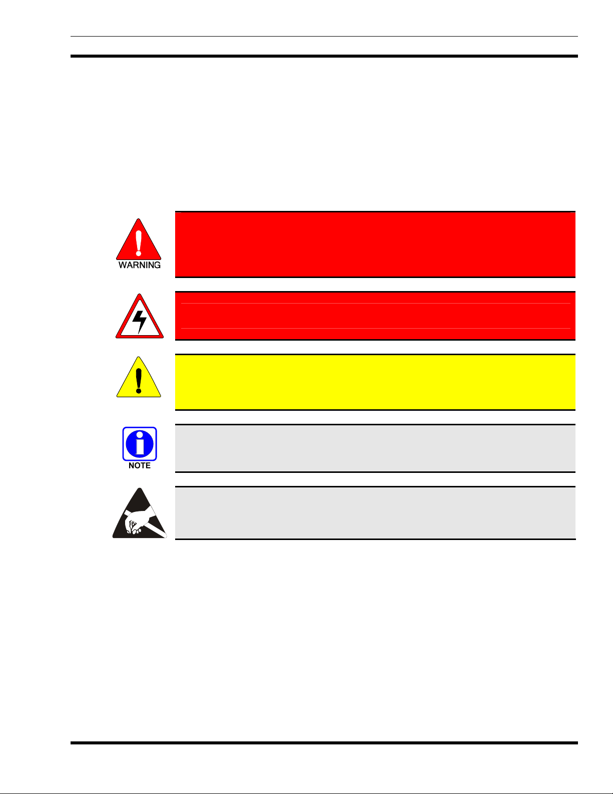
The WARNING symbol calls attention to a procedure, practice, or the like, which,
if not correctly performed or adhered to, could result in personal injury. Do not
proceed beyond a WARNING symbol until the conditions identified are fully
understood or met.
The electrical hazard symbol indicates there is an electrical shock hazard present!
MM-009290-001
The CAUTION symbol calls attention to an operating procedure, practice, or the like,
which, if not performed correctly or adhered to, could result in damage to the
CAUTION
equipment or severely degrade equipment performance.
The NOTE symbol calls attention to supplemental information, which may improve
system performance or clarify a process or procedure.
The ESD symbol calls attention to procedures, practices, or the like, which could
expose equipment to the effects of Electro-Static Discharge. Proper precautions must be
taken to prevent ESD when handling circuit modules.
5
Page 7
MM-009290-001
1.2 MAXIMUM PERMISSIBLE EXPOSURE LIMITS
DO NOT TRANSMIT with this base station and its antenna when persons are within the MAXIMUM
PERMISSIBLE EXPOSURE (MPE) radius of the radio frequency (RF) antenna. The MPE radius is the
minimum distance from the antenna axis that ALL persons should maintain in order to avoid RF exposure
higher than the allowable MPE level set by the FCC.
FAILURE TO OBSERVE THESE LIMITS MAY ALLOW ALL PERSONS
WITHIN THE MPE RADIUS TO EXPERIENCE RF RADIATION
ABSORPTION, WHICH EXCEEDS THE FCC MAXIMUM PERMISSIBLE
EXPOSURE (MPE) LIMIT. IT IS THE RESPONSIBILITY OF THE BASE
STATION OPERATOR TO ENSURE THAT THE MAXIMUM PERMISSIBLE
EXPOSURE LIMITS ARE OBSERVED AT ALL TIMES DURING BASE
STATION TRANSMISSION. THE BASE STATION OPERATOR MUST
ENSURE NO BYSTANDERS ARE WITHIN THE MPE RADIUS LIMITS
WHEN THE STATION IS TRANSMITTING.
1.3 DETERMINING MPE RADIUS
THE MAXIMUM PERMISSIBLE EXPOSURE RADIUS is unique for each site and is determined
during site licensing time based on the complete installation environment (i.e. co-location, antenna type,
transmit power level, etc.). Determination of the MPE radius is the responsibility of the installation
licensee. Calculation of the MPE radius is required as part of the site licensing procedure with the FCC.
1.4 SAFETY TRAINING INFORMATION
THIS BASE STATION GENERATES RADIO FREQUENCY (RF) ELECTROMAGNETIC ENERGY WHEN IT IS TRANSMITTING. THIS BASE STATION
IS DESIGNED FOR AND CLASSIFIED AS “OCCUPATIONAL USE ONLY,”
MEANING IT MUST BE USED ONLY IN THE COURSE OF EMPLOYMENT
BY INDIVIDUALS AWARE OF THE HAZARDS AND THE WAYS TO
MINIMIZE SUCH HAZARDS. THIS BASE STATION IS NOT INTENDED
FOR USE BY THE “GENERAL POPULATION” IN AN UNCONTROLLED
ENVIRONMENT. IT IS THE RESPONSIBILITY OF THE BASE STATION
OPERATOR TO ENSURE THE MAXIMUM PERMISSIBLE EXPOSURE
LIMITS ARE OBSERVED AT ALL TIMES DURING STATION
TRANSMISSIONS. THE BASE STATION OPERATOR IS TO ENSURE THAT
NO BYSTANDERS COME WITHIN THE RADIUS OF THE MAXIMUM
PERMISSIBLE EXPOSURE LIMITS.
When licensed by the FCC, this base station complies with the FCC RF exposure limits when persons are
beyond the MPE radius of the antenna. In addition, the M/A-COM base station’s installation complies
with the following Standards and Guidelines with regard to RF energy and electromagnetic energy levels
and evaluation of such levels for exposure to humans:
• FCC OET Bulletin 65 Edition 97-01 Supplement C, Evaluating Compliance with FCC
Guidelines for Human Exposure to Radio Frequency Electromagnetic Fields.
6
Page 8
• American National Standards Institute (C95.1 – 1992), IEEE Standard for Safety Levels
with Respect to Human Exposure to Radio Frequency Electromagnetic Fields, 3 kHz to 300
GHz.
• American National Standards Institute (C95.3 – 1992), IEEE Recommended Practice for
the Measurement of Potentially Hazardous Electromagnetic Fields – RF and Microwave.
TO ENSURE HUMAN EXPOSURE TO RF ELECTROMAGNETIC ENERGY IS
WITHIN THE FCC ALLOWABLE LIMITS FOR OCCUPATIONAL USE, DO NOT
OPERATE THE BASE STATION IN A MANNER THAT WOULD CREATE AN
CAUTION
MPE RADIUS IN EXCESS OF THAT ALLOWED BY THE FCC.
Changes or modifications not expressly approved by M/A-COM Inc. could void the
user’s authority to operate the equipment.
CAUTION
1.5 IMPORTANT SAFETY INFORMATION
MM-009290-001
The following general safety precautions must be observed during all phases of operation, service, and
repair of this product. Failure to comply with these precautions or with specific warnings elsewhere in
this manual violates safety standards of design, manufacture, and intended use of the product.
M/A-COM
®
Inc. assumes no liability for the customer's failure to comply with these standards.
SAVE THIS MANUAL — It contains important safety, installation, and operating instructions.
1. BEFORE USING THIS EQUIPMENT, please follow and adhere to all warnings, safety and
operating instructions located on the product and in this manual.
2. GROUNDING AND POWER CONNECTION — To reduce risk of electrical shock and to
minimize exposure to radio frequency (RF) energy, connect the equipment to a properly grounded
power source and site ground point as described in this manual.
3. MAXIMUM PERMISSIBLE RF EXPOSURE LIMITS —This equipment generates and uses RF
energy. Any changes or modifications to this equipment not expressly approved by M/A-COM may
cause harmful interference and could void the user’s authority to operate the equipment.
4. ELECTROSTATIC DISCHARGE SENSITIVE COMPONENTS — This equipment contains
electronic components that may be damaged by electrostatic discharge. Proper precaution must be
taken when handling circuit modules. As a minimum, grounded wrist straps should be used at all
times when handling circuit modules.
5. Care should be taken so objects do not fall onto or liquids do not spill into the interior of the
equipment.
6. DO NOT connect auxiliary equipment not recommended or sold by M/A-COM. To do so may result
in the risk of fire, electric shock or injury to persons.
7. DO NOT attempt to operate this product in an explosive atmosphere unless it has been specifically
certified for such operation.
7
Page 9

MM-009290-001
8. To reduce risk of electric shock, isolate the unit and disconnect electrical power before attempting
any maintenance or interior cleaning.
9. Use only fuses of the correct type, voltage rating and current rating as specified in the parts list.
Failure to do so can result in fire hazard.
8
Page 10

2. SPECIFICATIONS
2.1 GENERAL
Dimensions, Less Mounting Bracket: 21.5 x 18 x 22 inches (546 x 457 x 559 millimeters)
(Height x Width x Depth)
Weight, Less Mounting Bracket
Packed for Shipment: < 100 pounds (45 kilograms)
Unpacked: < 90 pounds (40 kilograms)
Operating Temperature Range: -22 to +122° Fahrenheit (-30 to +50° Celsius)
Storage Temperature Range: -40 to +158° Fahrenheit (-40 to +70° Celsius)
Humidity: 95% maximum relative humidity @ 122° F (50° C)
Altitude:
Operating: 15,000 feet (4572 meters) maximum
Non-Operating: 30,000 feet (9144 meters) maximum
MM-009290-001
DC Supply Voltage
Nominal Operating Input Voltage: 27 Vdc (negative ground system)
Acceptable Input Voltage Range: 21 to 27.75 Vdc (for full specifications)
Maximum Input Ripple Voltage: 200 millivolts peak-to-peak at 7 amps
DC Supply Current:
700 MHz Base Station Only: 6.75 amps maximum at 27 Vdc
700 MHz Base Station & T1/FT1 Router: 7.0 amps maximum at 27 Vdc
AC Supply/Charger Volts/Amps: (See SkyCharger documentation)
2.2 700 MHZ TRANSCEIVER
2.2.1 General
Frequency Ranges
Transmit (Narrowband Channels Only): 764 to 767 MHz and 773 to 776 MHz
Receive (Narrowband Channels Only): 794 to 797 MHz and 803 to 806 MHz
RF Channel Bandwidth: 25 kHz
RF Channel Available Step Size: 6.25 kHz
RF Transmit-to-Receive Frequency Offset: 30 MHz (typical)
9
Page 11

MM-009290-001
Modulation Type: 4-Level GFSK1 (9600 sym./sec. for 19.2 kbps/channel)
Data Communications Mode: Full-Duplex
Voice Communications Mode: Half-Duplex (per voice path)
Reference Oscillator Stability: 0.1 ppm
Antenna Ports’ Impedances: 50 ohms
Digital Data Transmission/Reception
Aggregate Forward Channel Rate: 19.2 kbps
Aggregate Reverse Channel Rate: 2 x 9.6 kbps (2 time slots)
Voice/Data DSP2 Compression Technique: Advanced Multi-Band Excitation (AMBE™)
Compressed Voice Relative Data Rate: 2400 bps
2.2.2 Transmitter
Output Power at Tx Antenna Port
With Duplex Antenna Option: 3 to 25 watts (35 to 44 dBm)
With Simplex Antenna Option: 3 to 31.5 watts (35 to 45 dBm)
Duty Cycle Rating: Continuous (100%) at 25 watts
FM Hum and Noise: > 37 dB per TIA-603 test method
Adjacent Channel Power Ratio (ACPR): Per FCC Part 90.543
2.2.3 Receiver
Sensitivity: -111 dBm minimum for 1% Block Error Rate
Intermodulation Rejection: > 85 dB per TIA-603 test method
Adjacent Channel Rejection: > 80 dB per TIA-603 test method
Spurious Response Rejection: > 90 dB per TIA-603 test method
Conducted Spurious Emission: No spurious emissions from antenna output ports
exceeding -57 dBm (FCC Part 15)
2.2.4 Regulatory
FCC Type Acceptance ID Number: BV8CS700
Applicable FCC Rules: Part 90 and Part 15
1
Gaussian Frequency-Shift Keying (GFSK) is a modulation format that employs Gaussian filters for spectral efficiency,
and carrier frequency-shift modulation techniques.
2
Digital Signal Processing/Processor (DSP)
10
Page 12

Industry Canada Certification Number: 3670A-CS700
2.3 SITE-TO-SITE (BACKHAUL) COMMUNICATIONS
2.3.1 T1/FT1 Frame-Relay Router Option MACS-NDF1Y
Protocol Utilized: RFC 1490 encapsulation (multi-protocol over frame
relay)
LMI Type: LMI, ANSI (Annex D), CCITT (Annex A) and static
Data Throughput Rate: 64 kbps to approximately 1.5 Mbps
BSC-to-Router Communication Link
Local Area Network (LAN) Interface: 10/100-Base-T Ethernet (10/100 Mbps)
LAN Port Connections: RJ-45 modular jacks provided on internal side of
Customer Interface Board; surge-protected interface
T1 Line Connection Port: RJ-45 modular jack provided on external side of
Customer Interface Board; surge-protected interface
MM-009290-001
Applicable FCC Rules: Part 68
Industry Canada Certification Number: CS03
2.3.2 56 Kbps DDS Modem Router Option MACS-NDF1Z
Protocol: Synchronous Digital Data Service (DDS)
Data Throughput Rate: 56 kbps maximum
BSC-to-Router Communication Link
Local Area Network (LAN) Interface: 10/100-Base-T Ethernet (10/100 Mbps)
LAN Port Connections: RJ-45 modular jacks provided on internal side of
Customer Interface Board; surge-protected interface
Telco Line Connection Port: RJ-45 modular jack provided on external side of
Customer Interface Board; surge-protected interface
Dial Backup (DBU) Port: RJ-45 modular jack provided on external side of
Customer Interface Board; surge-protected interface
Applicable FCC Rules: Part 68
11
Page 13

MM-009290-001
3. INTRODUCTION
3.1 ABOUT THIS MANUAL
This manual contains installation instructions, configuration and test procedures for the OpenSky
700 MHz Cell Site base station equipment. It is intended for use by M/A-COM and/or M/A-COMcontracted personnel responsible for supervising or conducting the equipment installation process. Before
attempting to install or test this equipment, familiarity with the contents of this manual is recommended.
This manual is divided into the following sections:
1. SAFETY AND REGULATORY INFORMATION — This section includes safety information
which must be observed at all times!
2. SPECIFICATIONS — This section includes general specifications for the equipment.
3. INTRODUCTION — This section introduces the reader to the contents of this manual, provides a
brief overview of the equipment, and includes a list of related documentation. It also includes lists of
recommended tools and test equipment.
4. SITE PREPARATION — This section includes general antenna system installation information and
general facility requirements such as AC/DC electrical power requirements. It also includes
instructions for unpacking the base station equipment upon receipt.
5. MECHANICAL INSTALLATION — This section includes cabinet mechanical installation
instructions. Instructions for pole-mount, tower-mount, and in-building installations is included.
6. ELECTRICAL INSTALLATION — This section includes electrical installation instructions such
as antenna connections, AC/DC electrical power connections, and backhaul link connections.
®
7. POWER-UP PROCEDURE — The recommended power-up procedure is included in this section.
8. CONFIGURATION — This section provides instructions for setting-up the equipment for
operations on an OpenSky radio network.
12
Page 14
3.2 GENERAL INFORMATION
M/A-COM’s OpenSky® 700 MHz Cell Site base station is a stand-alone fully-digital trunked base station
for 700 MHz OpenSky trunked radio networks. Housed in a compact and easy-to-install weather-resistant
cabinet, it can be pole mounted, tower mounted or wall mounted. The Cell Site base station requires a colocated continuous-duty 24-volt DC power source, a 700 MHz antenna system, and site-to-site backhaul
communication equipment to link it to the high-power SkyMASTR base station/tower site.
OpenSky employs Time-Division Multiple-Access (TDMA) digital modulation technology. TDMA
allows multiple users to share a single RF channel. Each channel can support simultaneous digital voice
and data communications, in either a 2-slot or 4-slot format.
The Cell Site base station operates in the OpenSky Trunking Protocol (OTP) mode on a single 25 kHz
wide 700 MHz RF channel. A key advantage of OTP mode is its internet protocol (IP) based
communication capability. The station has a RF transmit output power range that is configurable between
15 and 37 watts (35 to 45.7 dBm), with a 25-watt continuous-duty rating.
The Cell Site base station complements the wide area coverage of a high-power SkyMASTR base
station/tower site by providing a cost-effective RF coverage solution for problem areas. It provides
consistent RF coverage to low-traffic areas that require only a single (2-slot or 4-slot TDMA) channel for
voice and data communications. Cell Site base stations are typically employed in areas that are problem
coverage areas for the respective high-power tower site(s). In other words, those areas hard-to-reach from
an RF standpoint via the high-power tower site(s) due to difficult terrain or other geographic or manmade RF obstructions. In essence, a Cell Site base station is an extension of a high-power tower site’s
network of OpenSky base stations. A Cell Site base station can typically be deployed for one-tenth the
cost of a tower site with an equipment shelter.
MM-009290-001
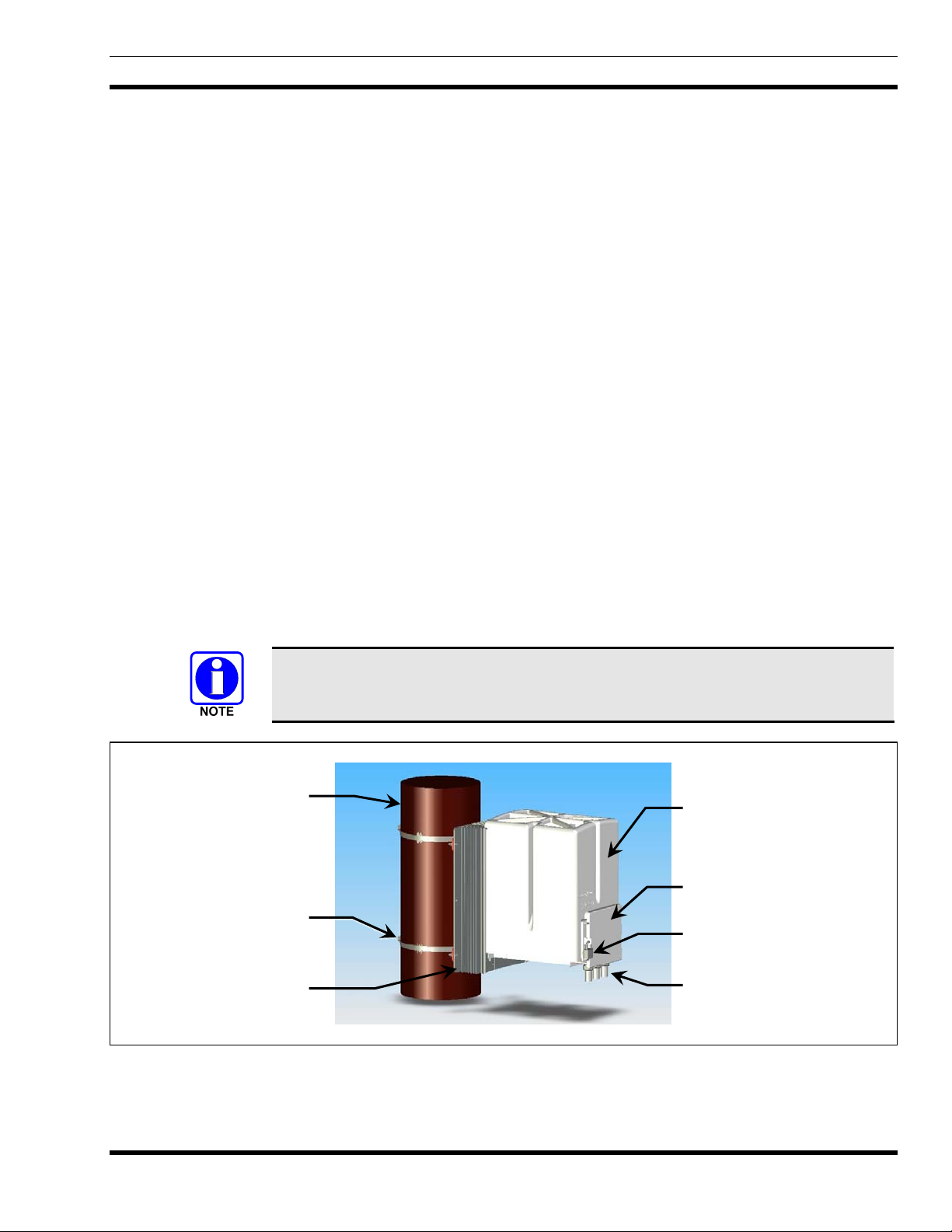
OpenSky system software up to release 4 utilizes 2-slot TDMA technology.
OpenSky system software release 5 and later utilizes 4-slot TDMA technology.
Wooden Pole
(cutaway view)
Anti-Sway Straps
and ¾-Inch Hardware
(2 places each)
Heat Sink Assembly for
Transmitter’s HPA
Solar Shield
Customer Interface Box
Access Door
Lock for Door
Feed-Thru Ports of
Customer Interface Box
Figure 3-1: Cell Site Base Station — Mounted on a 12-Inch Diameter Wooden Pole (Cabling Not Shown)
13
Page 15

MM-009290-001
r
Mounting Brackets
(2 places)
Wooden Pole
(cutaway view)
Anti-Sway Straps and
¾-Inch Hardware
(2 places each)
Receive Antenna Port/Connector Transmit Antenna Port/Connecto
Solar Shield
Door of Customer
Interface Box
Feed-Thru Ports of
Customer Interface Box
(3 total)
Auxiliary Antenna
Port/Connector B
Auxiliary Antenna
Port/Connector A
Bottom of Base Station
Figure 3-2: Cell Site Base Station — Bottom View (Cabling Not Shown)
Each Cell Site base station in an OpenSky trunked radio network is assigned to a SkyMASTR base
station/tower site within the trunked radio network. The Cell Site base station gains network connectivity
via a site-to-site backhaul communication link between itself and the main station/tower site. This is
accomplished using IP-based protocols over either a T1/Fractional T1 (FT1) frame-relay landline link, or
a 56 kbps Digital Data Service (DDS) landline modem link.
T1/FT1 frame-relay and DDS modem landline links are implemented via a router installed inside the base
station cabinet. For a T1/FT1 site-to-site communication link, the router is equipped with a T1/FT1
frame-relay option. For a DDS site-to-site communication link, the router is equipped with a DDS modem
option.
In an OpenSky trunked radio network, each SkyMASTR base station/tower site is assigned a block of
Class C internet protocol (IP) addresses. From these addresses, one address is used for the site-to-site
backhaul communication link.
Site-specific configuration parameters such as site ID, channel ID and site IP address, MDIS IP address,
VNIC IP address, etc. are typically loaded into the Cell Site’s Base Station Controller (BSC) before the
equipment ships from the factory. The BSC is a part of the station’s Digital Controller/Transceiver (DCX)
which is located inside the Cell Site base station cabinet.
14
Page 16

TX/RX
Antenna
Combined
MM-009290-001
27.2 Volts In
Lightning
Tx
LIghtning
27.2 Volts Out
Suppression
Rx
Duplexer
Suppression
12 Volts Out
Customer
Distribution
Interface/ Power
24 Volts Out
for duplex operation
Alternate configuration
12 Volts Out
SLIP
Ethernet/
Converter
SLIP
Ethernet
TX Antenna
Lightning
Suppression
Low Pass Filter
TX Out
RCV Antenna
Protection
Tower Top
Amplifier Bias
Feed/Lightening
RX In
Phone Line
Lightning
12 Volts in
Ethernet
Suppression
Router
SLIP
RF Out
RF Board
24V Volts In
Board
OpenSky 700 MHz Cell Site System Block Diagram
Controller
RF In
High Power Amplifier
RS-485
12 Volts In
RX In
RF Out
Base Station Transceiver
RS-485
TX RX
IIQ Q Vref
12 Volts In
EIA232
Network
Base Station Controller
Terminal1 COM 1
RS-485
Figure 3-3: Cell Site Base Station — System Block Diagram
15
Page 17

MM-009290-001
3.3 EQUIPMENT MODEL AND PART NUMBERS
Model and part numbers for this equipment and the related options are listed in the follow table:
Table 3-1: 700 MHz Cell Site Base Station Equipment Model and Part Numbers
(Major Assemblies and Options Only)
ASSEMBLY DESCRIPTION
OpenSky 700 MHz Cell Site Base Station; Includes: MACS-MC700
• 700 MHz DCX; Includes:
• Base Station Controller (BSC) Board Assembly
(Does not
• BSC Enclosure (Does not include board assembly)
• 700 MHz Base Station Transceiver (BSX) Board Assembly
(Does not include enclosure)
• BSX Enclosure (Does not include board assembly)
• 700 MHz 40-Watt HPA & Controller; Includes:
• 700 MHz 40-Watt HPA
• HPA Digital Controller
• Customer Interface Board
Kit, Heat Sink & Solar Shield Pole-Mount MACS-NCK1G
Option, Wooden Pole-Mount Kit MACS-NMA6D
Option, Metal Pole-Mount Kit MACS-NMA6E
include enclosure)
MODEL/PART
NUMBER
IA-008104-001
BG01049
FM-008100
1000011224
FM-008102
1000022909-0001
1000022937-0001
CB-008852
1000023295-0001
Option, 700 MHz Simplex Antenna MACS-NDU1W
Option, 700 MHz Duplex Antenna MACS-NDU1X
Option, T1/FT1 Router MACS-NDF1Y
Option, 56 kbps DDS Modem Router with DSU and DBU Connectivity MACS NDF1Z
Option, SkyCharger Battery Backup System MACBOS0003
16
Page 18

MM-009290-001
4. RECOMMENDED TOOLS, TEST EQUIPMENT AND
SOFTWARE
Lists of recommended tools, test equipment, and programming software are included in the tables in this
section. Other test equipment may be substituted providing it is equivalent in accuracy and performance
to the listed test equipment.
Table 4-1: Recommended Tools
DESCRIPTION USE/COMMENTS
½-Inch Drive Racket Used with below listed socket
½-Inch Drive, 1-¼-Inch Socket Needed only for wooded pole installations.
1-¼-Inch Wrench Needed only for wooded pole installations.
3/8-Inch Drive Racket Used with below listed socket
3/8-Inch Drive, 1/2-Inch Socket For securing ground to bus bar
12-Inch Nylon Wire Ties General cable/wire securing.
Assorted Hand Tools As needed for cabinet installation
Tape Measure, 25-Foot For making general distance measurements.
2 or 4-Foot Bubble Level
and/or
Electronic Laser Level
Drill with ½-inch Chuck For drilling holes in pole, etc.
Heavy-Duty (Industrial-Type)
Drill with 1-inch Chuck
7/8-Inch Drill Bit
Set of Standard Drill Bits For drilling holes in pole, etc.
Set of Masonry Drill Bits
Center Punch Used to punch hole centers prior to drilling holes.
Ground Cable (6 AWG green) For grounding equipment cabinets
Crimp-On 1-hole lugs For attaching cabinet ground cables to grounded surface
Crimp-On 2-hole lugs For attaching cabinet ground cables to grounded surface
For marking reference lines on mounting surfaces and
verifying mounted components are level.
Needed for wooden pole installations. Used for drilling
7/8-inch holes in the pole.
Needed for wooden pole installations. Used for drilling
7/8-inch holes in the pole.
Needed if the base station is mounted to a concrete or
cinder block wall.
Crimpers For crimping lugs to ground wire and power leads
Crowbar For opening shipping crates
Equipment Cart with 1,200
pound minimum lift capacity
17
For moving equipment cabinets
Page 19

MM-009290-001
DESCRIPTION USE/COMMENTS
Knife or Shears For cutting strapping around cabinet packaging
Table 4-1: Recommended Tools
Heat Gun For shrink tubing with control cable connector
Labeling System
Denatured Alcohol
Heat Transfer Compound
Recommended Type: P-Touch Labeling System, Model
PT-330
For cleaning heat transfer surfaces prior to applying heat
transfer compound.
Used between base station cabinet and Heat Sink
Assembly.
For tightening and loosening N-type connectors.
Soft-Jaw Connector Pliers
Recommended Type: M/A-COM Part Number 529-10 or
Tessco Part Number 83040
Soldering Gun For soldering leads of control cable connector
T1 Crimper
Recommended Type: AMP Hand Tool Part Number
2-231652-0
18
Page 20

MM-009290-001
Table 4-2: Recommended Test Equipment and Programming Software
DESCRIPTION MODEL/PART NUMBER USE
RF Communication Test
Set (Service Monitor)
RF Power Meter Agilent 437 with 8481H power sensor
Agilent ESG-D with option UND
(or equivalent) with cables
RF signal source for test and
alignment.
Used for measuring RF power
levels.
50-Ohm RF Load(s) Bird 8135 Test and alignment.
True-RMS Digital
Multimeter (DMM)
OpenSky
Portable Radios
Personal Computer (PC)
M/A-COM P801 or P7200 Series
(Use customer’s radios if available)
(laptop-type recommended; see Table
4-3 for minimum requirements)
Fluke 87-Series Test and alignment.
Test and alignment.
3
Test and alignment.
Table 4-3: Personal Computer Minimum Requirements (PC Used for Local Configuration and Testing)
PARAMETER
WINDOWS® NT 4.0
(Service Pack 4)
WINDOWS 2000 WINDOWS XP
Processor Speed: Pentium II 90 MHz Pentium II 133 MHz Pentium II 233 MHz
RAM: 128 Megabytes 128 Megabytes 128 Megabytes
Hard Drive Free Space: 160 Megabytes 160 Megabytes 160 Megabytes
Other Drives: CD-ROM CD-ROM CD-ROM
Ports: 1 Serial or Ethernet 1 Serial or Ethernet 1 Serial or Ethernet
Microsoft Internet Explorer:
Version 5.01
or higher
Version 5.01
or higher
Version 5.01
or higher
Network: LAN LAN LAN
3
If the system supports digital encryption, radios capable of the same digital voice mode are required. For example, if
128-bit AES encryption is utilized in the system, radios capable of 128-bit AES encryption are required for complete testing.
19
Page 21

MM-009290-001
5. SITE PREPARATION
5.1 BEFORE BEGINNING THE INSTALLATION
Before beginning an installation, collect information from the Site Deployment Order (SDO)
specific to the site access such as:
• Permission to access the site.
• Important contact names and telephone numbers.
• Location of and directions to the site.
• Keys and/or lock combinations to access the site and equipment shelter (if any), or points of
contact to obtain them.
• Site entry alarm system pass-codes and/or disable keys.
• Information about work practices needed to work safely at the site.
Other important information that may or may not be included on the SDO includes:
• Type of mounting—metal pole, wooden pole, tower base, exterior wall, etc.
• Drawing or description of each site showing how the equipment is to be installed.
• Applicable inspections completed (pole installation, electrical, local build code, etc.)
Keep the working environment clean!
Control dust, dirt, and shavings for safety, and to protect the equipment.
CAUTION
Be sure to follow installation procedures carefully!
5.2 POLE-MOUNT INSTALLATIONS
Contact a local utility company and arrange for installation of the required pole type. Refer to the Site
Deployment Order (SDO) and other applicable site installation information as necessary. Typically, a
60- or 70-foot tall 12-inch diameter pole is employed, with at least 10 feet of the pole buried in the
ground.
5.3 ELECTRICAL POWER
5.3.1 AC Power
A Cell Site base station site equipped with a SkyCharger battery backup system requires 100-amp AC
electrical service:
• Contact the local electrical utility company and arrange for installation of 100-amp electrical
service at the site (to the pole/pad/wall/etc.) Either over-head or under-ground service may be
used; however, under-ground service is recommended for improved safety. If over-head service is
used, it can be either 100 or 200-amp rated to the base of the power meter. However, if underground service is used, it must be 200-amp rated (minimum) to the base of the power meter.
20
Page 22
MM-009290-001
• The installed power meter must be rated at 200 amps minimum. For pole-mount installations, the
meter is normally installed 90 degrees from the Cell Site base station cabinet, and 90 degrees
from the SkyCharger battery backup system cabinet. When facing the pole with the Cell Site
cabinet on the left and the SkyCharger cabinet on the right, the power meter is located on the far
side of the pole. Power meter egress conduit type, size and related wiring should meet all local
building codes.
• An AC circuit breaker box must be installed. Typically, a 6-breaker load center box is used. For
pole-mount installations, the breaker box is normally installed on the pole 180 degrees from the
power meter. In other words, when facing the pole with the Cell Site cabinet on the left and the
SkyCharger cabinet on the right, the circuit breaker box is located on the near side of the pole. All
breaker box egress conduit and related wiring should meet all local building codes. Typically,
¾-inch GRS-type conduit is employed.
• A 20-amp Ground Fault Interrupt (GFI) duplex AC receptacle box should be installed just under
or beside the AC circuit breaker box. This receptacle is for auxiliary use by installation and
service personnel. It should be connected to an independent breaker located in the AC circuit
breaker box. This breaker should remain in the OFF position when installation/service personnel
are not using it. Box installation, conduit and wiring servicing this box should meet all local
building codes. Typically, ¾-inch GRS-type conduit is employed.
All AC circuit breakers for site equipment must remain OFF during equipment
installation. The circuit breaker for the auxiliary duplex AC receptacle (if any) can
remain on as needed by installation and service personnel.
AC power installation methods must conform to all applicable local installation
regulations and/or local building codes, including but not limited to the utilization
of the proper AC receptacle and circuit breaker combination.
If the SkyCharger battery backup system is not used, refer to the sections 5.3.3 and 5.3.4 for additional
information.
5.3.2 Generator Power
Some systems require emergency generators with automatic switchover systems. The generators must be
connected to the external site grounding system and should be located in an outdoor location. There
should only be one neutral/ground bond at the site per NEC code. Automatic switchover systems must be
disabled during installation.
5.3.3 DC Power
The Cell Site base station requires a 27-volt (nominal) DC power source. This source must have a
continuous-duty current rating of at least 10 amps, with a ripple of less than 200 mV peak-to-peak at
7 amps, or 250 mV peak-to-peak at 10 amps. Refer to the specifications section on page 9 for additional
information.
Typically, the SkyCharger battery backup system is employed to supply DC power to the Cell Site base
station, both during normal operating periods and on a temporary backup basis when the site loses AC
power. Battery hold-up time may be specified in the equipment contract and/or on the SDO. Refer to the
SkyCharger installation manual (MM20963) included with this manual set.
21
Page 23
MM-009290-001
5.3.4 If the SkyCharger Battery Backup Power System is Not Used
Some systems require battery backup power connected to the supply system in case of an AC power
failure. Preferably, the battery bank should be in a room separate from the radio equipment. If located in
the same room as the radio equipment, the battery bank should be at a point furthest from the equipment
room entrance/door. In either case, it should have a separate fume extraction system or it should be
located directly below the air extraction system for the site.
If the SkyCharger battery backup system is not employed, consult the site’s SDO and/or the respective
vendor’s DC power supply system installation instructions for additional information or special
instructions that may apply. In any case, as previously stated, the DC supply system powering the Cell
Site cabinet must have a 10-amp (minimum) continuous-duty current rating. Battery hold-up time may be
specified in the equipment contract and/or on the SDO.
Like AC power installations methods, a DC power installation methods must
conform to all applicable local installation regulations and/or local building codes.
NEVER locate batteries near the air intake(s) of an air conditioning or air
circulation system!
Always minimize the risk of contact between lead-acid batteries and aluminum
alloys!
5.4 GROUNDING THE EQUIPMENT
Ensure all equipment and facilities meet the requirements for grounding and lightning protection. Site
Grounding and Lightning Protection Guidelines manual AE/LZT 123 4618/1 provides proper grounding
procedures. These guidelines must be observed in order to protect the equipment and service personnel
from lightning and other sources of electrical surges. See section 7.1 in this manual for additional
information.
Proper grounding also ensures the MPE radius of the radio frequency (RF) antenna is maintained. The
MPE radius is the minimum distance from the antenna axis that ALL persons should maintain in order to
avoid RF exposure higher than the allowable MPE level set by the FCC. Refer to section 1 which begins
on page 5 for additional information.
5.5 ANTENNA SYSTEM
This section is an overview of the antenna system installation. It includes general antenna installation
guidelines and installation information for the respective antenna RF coaxial cables.
22
Page 24

MM-009290-001
Antenna systems are generally installed by crews specially-trained and equipped for working on antenna
towers and/or pole-type installations. As a result, this manual assumes skilled personnel of this type will
be working on the towers/poles, and installing the antennas and antenna cables. However, it may be
necessary for the system installer to provide information and directions to the crew, and to verify proper
installation.
5.5.1 Antenna Mounting
5.5.1.1 Simplex Antennas
If the installation utilizes simplex antennas (i.e., separate transmit and receive antennas), the Cell Site
base station must be equipped with M/A-COM option MACS-NDU1W. With simplex antennas, antenna
installation/mounting locations must provide least 25 dB of isolation between the TX and RX antennas.
This is necessary to avoid interference in the receiver caused by the transmitter. An isolation of greater
than 25 dB is easily obtained by mounting the transmit antenna at least ten (10) feet above the receive
antenna.
5.5.1.2 Duplex Antenna
If the installation utilizes a duplex antenna system (i.e., one antenna for both transmit and receive), the
Cell Site base station must be equipped with M/A-COM option MACS-NDU1X. In installations of this
type, the respective antenna is normally mounted at the top of the pole.
5.5.2 RF Coaxial Cables
When installing antenna RF coaxial cables, refer to the applicable antenna assembly drawing(s) shown in
Antenna Systems manual LBI-38983, which is included with this set of manuals.
5.5.2.1 Cable Length
The length of the main coaxial cable for each antenna should be a continuous run with no connectors or
splices. Smaller diameter, more flexible coaxial cable is typically used at cabinet end of the main coaxial
cable to facilitate cable connection and disconnection, formation of drip loops, etc.
5.5.2.2 Cable Minimum-Bend Radius
Always adhere to the cable manufacturer’s minimum-bend radius specification. For Andrew cable, the
values are listed in the following table. For another cable brand, consult the respective manufacture’s
recommendations.
23
Page 25
MM-009290-001
Table 5-1: Minimum-Bend Radius for Andrew HELIAX® 50-Ohm Foam Dielectric Coax Cable
CABLE SIZE TYPE ANDREW PART NUMBER MINIMUM-BEND RADIUS
1/4-inch Super-flexible FSJ1-50A 1 inch (25 mm)
3/8-inch Super-flexible FSJ2-50 1 inch (25 mm)
1/2-inch Super-flexible FSJ4-50B 1.25 inches (32 mm)
1/2-inch Hard-line LDF4-50A 5.0 inches (125 mm)
7/8-inch Hard-line LDF5-50A 10 inches (250 mm)
1-1/4-inch Hard-line LDF6-50 15 inches (380 mm)
1-5/8-inch Hard-line LDF7-50A 20 inches (510 mm)
5.5.2.3 Hoisting Grips
Hoisting grips provide the means to attach a lifting mechanism to the coaxial cable without damaging it.
Typically, each hoisting grip is capable of safely lifting 200 feet of cable without causing cable damage.
Therefore, one hoisting grip is required for every 200-foot cable section. Grips may be left attached to the
cable after the cable installation is completed.
Some situations may require more hoisting grips, such as:
• An installation on a tower which is on top of another structure; or,
• Any installation where the lengths of cable that must be lifted is greater than the height of the
tower/pole.
In these situations, additional hoisting grips should be ordered and used as needed.
Never attach lifting ropes or hoisting grips to an RF connector on the end of a coax cable.
CAUTION
5.5.2.4 Hangers and Adapters
Coaxial cables on the tower/pole should be secured at 3-foot intervals (maximum distance). Securing
7/8-inch and 1-5/8-inch diameter coaxial cables is accomplished by using either hangers or hangeradapter combinations. The hangers secure the cables to the tower/pole structure by using pre-punched
holes or attachment adapters.
• For wooden poles, shelf-thread lag bolts should be used.
• When a tower structure is pre-punched with 3/4-inch holes, snap-in hangers should be used.
• When a tower structure is pre-punched with 3/8-inch holes, each hanger should be secured with a
3/8-inch bolt.
• For towers without pre-punched holes, hangers and adapters are available for either angle tower
members or round tower members.
24
Page 26

MM-009290-001
Adapters for each antenna system are selected when ordering the system. If antenna coaxial cable must be
attached to a structure that is not compatible with any of the previously described hangers or adapters,
additional materials or other special considerations may be required.
To secure 1/4-inch or 1/2-inch vertical or horizontal coaxial cables of any size, the use of heavy-duty
nylon cable ties is recommended.
5.5.2.5 Weatherproofing Connectors
A kit of weatherproof tape is normally provided to protect coaxial connectors from the outside elements.
Follow all cable manufacturer weatherproofing guidelines.
5.5.2.6 RF Entry Point (Wall Feed-Thrus)
If the Cell Site base station cabinet is located inside an equipment room, the room’s RF entry point (wall
feed-thrus) should be installed and the respective bulkhead grounded in accordance with the procedures
presented in Site Grounding and Lightning Protection Guidelines manual AE/LZT 123 4618/1 (manual
include with this manual set).
5.5.2.7 Grounding Transmission Lines and Surge Protection Devices (SPDs)
All RF transmission lines and surge protection devices (SPDs) should be grounded in accordance with
procedures presented in Site Grounding and Lightning Protection Guidelines manual AE/LZT 123
4618/1. AE/LZT 123 4618/1 is include with this set of installation manuals.
5.6 SITE-TO-SITE (BACKHAUL) COMMUNICATION LINKS
If the Cell Site base station will employ a landline backhaul communications link (i.e., the router with the
T1/FT1 frame relay option or the router with the 56 kbps DDS modem option) for the site-to-site
backhaul communication link, suitable lines should be in-place before beginning site installation.
Typically, lines are ordered from and supplied by the local telephone company. Interfaces will be agreed
demarcation points to which the customer/installer will make connections.
• For pole-mount installations, the Telco connection box is normally mounted on the same side of
the pole as the Cell Site cabinet. Some installations use a NEMA (Type 12, 13, 4) box such as
Hammond Manufacturing’s EJ12126.
• For other type installations, the Telco connection box can be mounted at any nearby approved
mounting surface such as the exterior wall of an equipment building.
5.7 UNPACKING THE BASE STATION EQUIPMENT
Cell Site base station equipment is generally packed in mini-pallets approximately 36 inches deep by 32
inches wide. These pallets can generally be moved with a medium-duty hand-truck. A crowbar and
hammer will be useful for opening the crates. Wrenches will be needed to unbolt the cabinets from the
pallets.
Carefully examine each carton upon receipt. If any packaging damage is detected, note the damage on the
Bill of Lading.
25
Page 27

MM-009290-001
Before unpacking a pallet or crate, move it as close as possible to the installation location.
Carefully unpack the equipment and examine each item for damage. If any, contact the carrier
immediately and have their representative verify the damage. Failure to report shipping damage
immediately may cause forfeiture of any claim against the carrier.
When unpacking the equipment, check the contents against the packing list. Contact your M/A-COM
representative and the carrier if any discrepancies are noted.
After unpacking, carefully open each cabinet and inspect its contents to ensure the enclosed equipment
has not been damaged during delivery. If damage has occurred, note details of the damage and, if
necessary, contact the carrier immediately and have their representative verify the damage. Contact your
M/A-COM representative if the damage is such that installation cannot proceed.
26
Page 28

6. MECHANICAL INSTALLATION
This section includes mechanical installation procedures for the 700 MHz Cell Site base station and the
related equipment. Because of the wide variety of installation conditions and configurations, many
installations will require unique mechanical installation planning processes which must be accomplished
on a site-by-site basis. For example, installers typically encounter several different types of mechanical
installation scenarios such as wooden pole or metal pole mounting, optional cabinets that must be
installed on the same pole as the Cell Site base station, if the battery cabinet is installed on the same side
of the pole or the opposite side of the pole, etc.
The Site Deployment Order (SDO) should include an accurate site layout map, information to designate
equipment locations, and other necessary installation information.
Unless otherwise stated, all installation procedures presented in this section should be
performed in the order presented.
6.1 MOUNTING THE CELL SITE BASE STATION
MM-009290-001
Mounting the Cell Site base station typically involves attaching its mounting brackets to the mounting
surface (i.e., wooden pole, metal pole, tower base), attaching the base station’s Heat Sink Assembly to the
mounting brackets, lifting the base station cabinet and bolting it to the Heat Sink Assembly, and attaching
the cabinet’s solar shield. However, if the base station is mounted to a flat surface, no bracket is required
since the Heat Sink Assembly is simply bolted directly to the mounting surface.
Cell Site base station installations typically employ 60 or 70-foot-tall 12-inch-diameter wooden or metal
poles, with at least 10 feet of the pole buried into the ground. Two pole-mount installation kits are
available—one for wooden poles and one for metal poles. Each kit contains two (2) mounting brackets
and hardware for attaching the brackets to the pole. See Table 6-1 and Table 6-2 for kit contents.
6.1.1 Attaching the Mounting Brackets to a Wooden Pole
The following procedure is recommended for wooden pole installations. It is assumed the pole is already
planted, and that it is vertically level to within 2 degrees:
1. Consult the SDO for the required height above ground specification, and any other mounting-related
instructions/requirements. Most installations require the bottom of the base station cabinet at a
distance of at least eight (8) feet from the surface of the ground.
2. On the base station cabinet-side of the pole, mark a drill-point location for the lower mounting
bracket’s bolt hole. The bottom of the cabinet will be at approximately this same level above ground.
However, the bottom edge of the Heat Sink Assembly will be approximately 3.5 inches lower than
this point after it is attached to the brackets. See Figure 6-1.
3. Using a bubble or a laser-type level for an accurate vertical reference line, mark a drill-point location
for the upper mounting bracket’s bolt hole exactly 16-¾ inches above the mark for the lower
bracket’s bolt hole. This mark must be directly above the mark for the lower bracket’s bolt hole. As
27
Page 29

MM-009290-001
illustrated in Figure 6-1, the two end holes in one of the brackets may be used as a measuring tool, as
these holes are exactly 16-¾ inches apart.
4. Using a centering-type gauge/tool, a level-equipped drill, and a 7/8-inch (0.875-inch) drill bit, drill
two 7/8-inch holes at the marked locations. These holes must pass through the pole’s diameter-line
(within approximately 5 degrees) and they must be perpendicular to the length of the pole (also within
approximately 5 degrees).
5. Attach the two (2) mounting brackets to the pole using the ¾-inch hardware included in Pole-Mount
Installation Kit MACS-NMA6D (for wooden poles). See Figure 6-1 and refer to Table 6-1 for kit
contents. Do not
the brackets (as described in a later section).
6. Advance to section 6.1.3, Attaching the Heat Sink Assembly to the Mounting Brackets (on page 30).
Measuring & Marking Hole Locations
and Using a Bracket to Mark Drilled 7/8-Inch
Location of Upper Bolt Hole Diameter Bolt Holes Mounted Brackets
torque this hardware until after the Heat Sink Assembly has been attached to
Upper Drill-Point Location
Lower
Drill-
Point
Location
16.75
Inches
For required height above ground,
refer to the SDO (or equivalent
document). Bottom of Heat Sink
Assembly will be approximately
3.5 inches below this level.
Ground Level
¾-Inch Mounting Hardware
(2 places at upper and lower
mounting brackets)
Figure 6-1: Attaching the Mounting Brackets to a 12-Inch Wooden Pole
28
Page 30

MM-009290-001
Table 6-1: Contents of Pole-Mount Installation Kit MACS-NMA6D for 12-Inch Diameter Wooden Poles
PART NUMBER
QTY.
PER KIT
DESCRIPTION NOTES
1000023950 2 Bracket, Mounting
Bolt, Hex-Head: ¾-Inch
TBD 2
Stainless-Steel, 14 inches
long)
TBD 4
TBD 4
Washer, Flat: ¾-Inch
Stainless-Steel
Washer, Split-Lock: ¾-Inch
Stainless-Steel
TBD 2 Anti-Sway Straps
6.1.2 Attaching the Mounting Brackets to a Metal Pole
The following procedure is recommended for metal pole installations. It is assumed the pole is already
planted and it is vertically level to within 2 degrees:
Used to mount Heat Sink Assembly
to a wooden or metal pole.
Used to attach brackets to a
wooden pole.
Used with above bolts.
Used with above bolts.
Used to prevent side-to-side
movement during strong winds, etc.
1. Consult the SDO for the required height above ground specification, and any other mounting-related
instructions/requirements. Most installations require the bottom of the base station cabinet at a
distance of at least eight (8) feet from the surface of the ground.
2. On the base station cabinet-side of the pole, mark a location for the lower mounting bracket’s bolt
hole. The bottom of the cabinet will be at approximately this same level above ground. However, the
bottom edge of the Heat Sink Assembly will be approximately 3.5 inches lower than this point after it
is attached to the brackets.
3. Using a bubble or a laser-type level for an accurate vertical reference line, mark a location for the
upper mounting bracket exactly 16-¾ inches above the mark for the lower bracket. As illustrated in
Figure 6-1, the two end holes in one of the brackets may be used as a measuring tool, as these holes
are exactly 16-¾ inches apart.
4. Using the two (2) stainless-steel straps included in Pole-Mount Installation Kit MACS-NMA6E (for
metal poles), attach the two brackets to the pole. Refer to Table 6-2 for kit contents. Tighten the straps
in accordance with the installations instructions included with the straps.
5. Add the anti-sway straps to the brackets in accordance with the included installation instructions.
6. Advance to section 6.1.3, Attaching the Heat Sink Assembly to the Mounting Brackets (on page 30).
29
Page 31

MM-009290-001
Table 6-2: Contents of Pole-Mount Installation Kit MACS-NMA6E for 12-Inch Diameter Metal Poles
PART NUMBER
QTY.
PER KIT
DESCRIPTION NOTES
1000023950 2 Bracket, Mounting
TBD 2 Straps, Stainless-Steel
TBD 2 Anti-Sway Straps
6.1.3 Attaching the Heat Sink Assembly to the Mounting Brackets
For pole-mount installations, Heat Sink Assembly MA-007498 must be attached to the mounting brackets
before the Cell Site base station cabinet is attached to it. This assembly is a part of Heat Sink & Solar
Shield Pole-Mount Kit MACS-NCK1G. Contents of this kit are listed in Table 6-3 on page 31. The Heat
Sink Assembly is mounted to the pole via Mounting Brackets 1000023950 and 3/8-inch stainless-steel
hardware. The following procedure is recommended:
If mounting the base station to a flat surface, mounting brackets are not required. In this
case, advance to section 6.1.4 on page 32 for installation information.
Used to mount Heat Sink Assembly
to a wooden or metal pole.
Used to mount bracket to metal
pole.
Used to prevent side-to-side
movement during strong winds, etc.
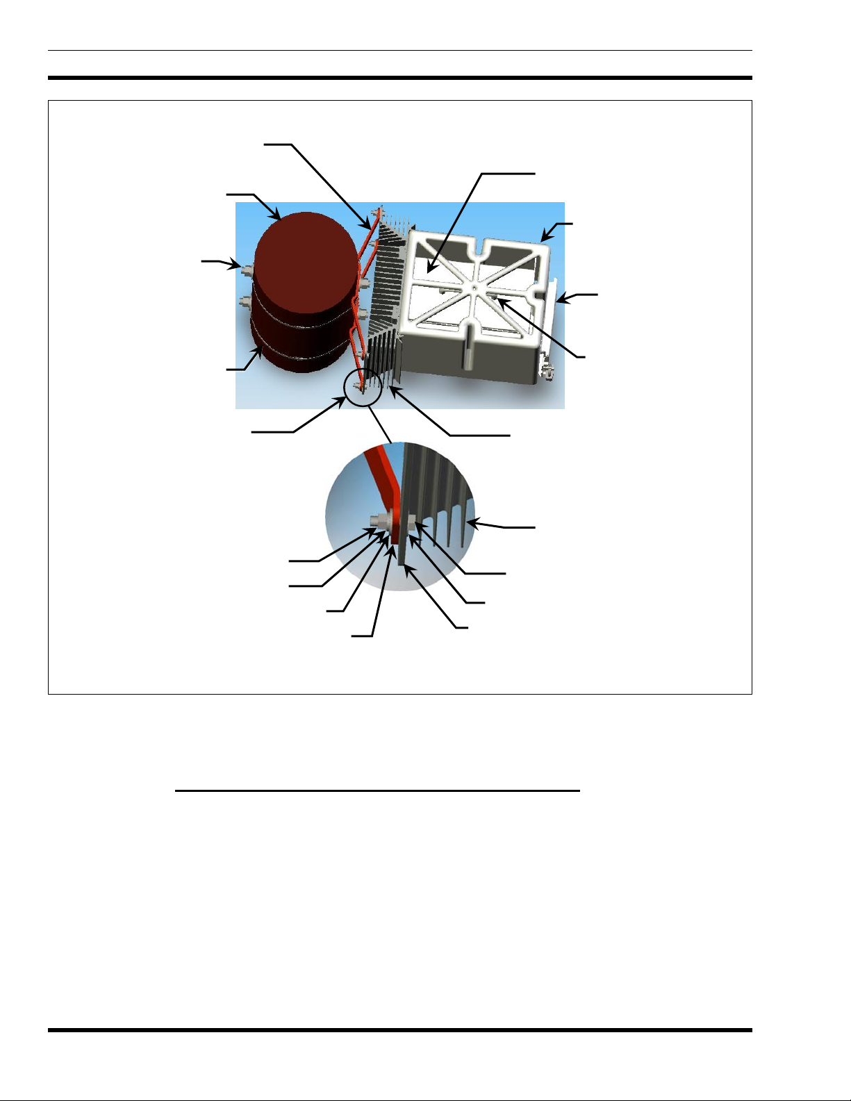
1. Loosely attach the Heat Sink Assembly to the two mounting brackets using the 1-3/8-inch long
(1.375-inch) 3/8-inch hex-head bolts, nuts, and washers included in the respective installation kit.
Start all hardware bolts before tightening any one bolt/washers/nut combination. See Figure 6-2.
2. Torque all of this 3/8-inch hardware to (TBD) pound-inches.
3. For wooden pole-mount installations, torque the ¾-inch bolts securing the two mounting brackets to
the pole to (TBD) pound-inches.
30
Page 32

MM-009290-001
Table 6-3: Contents of Heat Sink and Solar Shield Pole-Mount Kit MACS-NCK1G
PART NUMBER
QTY.
PER KIT
DESCRIPTION NOTES
MA-007498 1 Heat Sink Assembly
HT-008474 1 Thermal Gasket
Bolts, Hex-Head: 3/8-Inch
TBD 4
Stainless-Steel, 1-3/8-inches
long
TBD 4
Nuts, Hex: 3/8-Inch Stainless-
Steel
Bolts, Hex-Head: 3/8-Inch
92240A622 6
Stainless-Steel, 3/4 inches
long
92141A031 TBD
92146A031 TBD
Washers, Flat: 3/8-Inch
Stainless-Steel
Washers, Split-Lock: 3/8-Inch
Stainless-Steel
The finned aluminum assembly
external of the base station cabinet.
Used between the Heat Sink
Assembly and the back of the
station cabinet.
Used for securing Heat Sink
Assembly to the mounting brackets.
Used with above bolts.
Used for securing base station
cabinet to Heat Sink Assembly.
Used with above bolts.
Used with above bolts.
FM-008077 1 Shield, Solar
Shields base station cabinet from
the sun to help maintain
temperature inside the cabinet.
31
Page 33
MM-009290-001
r
NOTE: Base Station Cabinet and Solar Shield
are shown for reference only.
1/2-Inch Mounting
Hardware (2 places
for upper and lowe
Mounting Brackets
(2 places)
Wooden Pole
(cutaway view)
brackets)
Top of Base Station Cabinet
Solar Shield
Customer Interface
Box Access Door
Anti-Sway Straps
(2 places)
3/8-Inch Mounting Hardware
(4 places at brackets’ ends)
3/8-Inch Hex Nut
3/8-Inch Lock Washer
3/8-Inch Flat Washer
End of Mounting Bracket
Torque this 3/8-inch hardware to (TBD) pound-inches.
Figure 6-2: Attaching the Heat Sink Assembly to the Mounting Brackets
Heat Sink Assembly’s Mounting Stud
Heat Sink Assembly for
Transmitter’s HPA
3/8-Inch Hex-Head Bolt
3/8-Inch Flat Washer
(Top View; Wooden Pole Installation Shown)
Lifting Handle (Under
top of Solar Shield)
Fins of Heat Sink Assembly
6.1.4 Attaching the Heat Sink Assembly to a Flat Surface
Instead of pole or tower base mounting, the Cell Site base station may be mounted directly to a flat
surface such as the interior or exterior wall of an equipment shelter. This is accomplished by attaching its
Heat Sink Assembly directly to the flat surface. Six (6) 3/8-inch bolts are used to secure the Heat Sink
Assembly to the surface (not supplied). The following procedure is recommended:
1. Consult the SDO for the required height above ground specification, and any other mounting-related
instructions/requirements. Most installations require the bottom of the base station cabinet at a
distance of at least eight (8) feet from the surface of the ground.
32
Page 34

MM-009290-001
2. Obtain 3/8-inch hardware appropriate for the mounting surface. For example, if mounting to a
concrete wall, expandable concrete anchors with appropriate 3/8-inch bolts and washers are normally
used. Use of stainless-steel bolts and washers is recommended. For a flat surface that is less than
approximately ¾-inch thick, the 3/8-inch stainless-steel hardware in Pole-Mount Installation Kit
MACS-NMA6D (includes 1-3/8-inch long stainless-steel bolts) may be used if the opposite side of
the mounting surface is accessible. In this case, the two brackets in the kit are not
can be returned to stock or discarded.
A steel mounting surface must be grounded by ground wires/cables that are separate
from the wires/cables used to ground the base station cabinet.
CAUTION
Verify the mounting surface has no embedded electrical wires, water pipes, etc., or
other items on the opposite side such as fuel tanks, batteries, or equipment
cabinets. If so, adjust the location of the mounting surface as required so any
drilled holes and/or mounting bolts do not interfere with or penetrate items of this
type.
be used and they
3. Using a bubble or a laser-type level for an accurate vertical reference line, mark a vertical centerline
for the Heat Sink Assembly.
4. From this centerline, mark two (2) parallel lines exactly 8-3/8 inches (8.375 inches) from the
centerline. One line exactly 8-3/8 inches to the left of the centerline and one line exactly 8-3/8 inches
to the right of the centerline.
5. On the two (2) parallel lines, mark drill-points for the two bottom bolt holes. The bottom edge of the
Heat Sink Assembly will be approximately 3.5 inches lower than these points after it is attached to
the mounting surface. However, the bottom of the base station cabinet will be at approximately the
same level (height above ground) as these two bolt holes.
6. On the two parallel lines, mark drill-points for the two center bolt holes exactly 8-3/8 inches
(8.375 inches) above the bottom holes.
7. On the two parallel lines, mark drill-points for the two top bolt holes exactly 8-3/8 inches
(8.375 inches) above the center holes.
8. To verify the locations of the marked drill-points, position the Heat Sink Assembly over the points.
Adjust marks if they are incorrect.
9. Center-punch these six (6) drill-points and then drill pilot holes at the six drill-point locations. An
1/8-inch pilot hole is recommended.
10. Re-drill the six pilot holes to the required diameter according to utilized mounting hardware. Hole
diameter is typically 3/8-inch, unless anchor or toggle-type hardware is used which will typically
require larger holes.
11. Position the Heat Sink Assembly over the bolt holes and install the mounting hardware as required. A
flat washer must be used between the head of the each bolt and each mounting hole in the Heat Sink
33
Page 35
MM-009290-001
Assembly, and between each mounting hole in the Heat Sink Assembly and the mounting surface. If
the mounting surface is not nearly completely flat, additional flat washers should be used as required
to prevent bending of the Heat Sink Assembly when the bolts are torqued.
12. Torque the six (6) bolts as required per utilized hardware. Torque the two (2) center bolts (left and
right sides) first, then torque the four (4) corner bolts. Do not
Exceeding this torque spec could cause the Heat Sink Assembly to immediately crack, or crack later
during temperature cycles.
6.1.5 Attaching the Cabinet to the Heat Sink Assembly
After the Heat Sink Assembly is attached to its mounting surface, the Cell Site base station cabinet must
be attached to it per the following procedure:
1. Using a lint-free cloth dipped in denatured alcohol, clean the machined heat transfer surface at the
back of the base station cabinet and the corresponding surface on the Heat Sink Assembly. The
machined surface at the back of the cabinet is the portion of the station’s RF High-Power Amplifier
(HPA) heat sink and casting that is visible on the outside of the cabinet. This surface transfers heat to
the Heat Sink Assembly via a special thermal interface material applied later.
2. After cleaning, allow several minutes for the alcohol to evaporate.
exceed (TBD) pound/inches.
Observe and follow all recommended safety procedures, warnings, etc. listed by
the alcohol’s manufacturer and/or respective Material Safety Data Sheet (MSDS).
3. At the back of the base station cabinet, apply Thermal Interface Material HT-008474 (included with
installation kit) to the HPA’s machined heat transfer surface. This material has an adhesive side to
adhere to the machined surface, and a foil side which contacts the Heat Sink Assembly when the two
are joined together in the next step. Visually center the material parallel to the machined surface, then
lay it flat against the surface and use a gentle top-to-bottom sweeping motion to smoothly adhere the
material to the surface.
4. Using the cabinet’s lifting handle, carefully lift the cabinet and hang it on the Heat Sink Assembly by
the two (2) hooks at the top rear corners of the cabinet.
5. Slightly reposition the cabinet left or right as necessary to align the six (6) holes in the its rear panel
to the six corresponding threaded holes in the Heat Sink Assembly.
6. Start 3/8-inch mounting hardware in all six locations. Use a lock washer and a flat washer on each
bolt, with the lock washer adjacent to bolt head and the flat washer adjacent to rear panel hole. Do not
tighten any one bolt until all hardware has been started.
7. Torque all of the 3/8-inch mounting bolts to (TBD) pound-inches.
6.1.6 Install the Solar Shield Over the Cabinet
If not already, Solar Shield FM-008077 must be installed over the base station cabinet by attaching it to
the Heat Sink Assembly. This shield improves heat dissipation characteristics of the cabinet during
34
Page 36

daylight hours compared to an unshielded cabinet, and it helps to reduce build-up of foreign material on
the top of the cabinet. The Solar Shield is a part of Heat Sink & Solar Shield Pole Mount Kit option
MACS-NCK1G. Attach the shield to the cabinet in accordance with this procedure:
1. Position the Solar Shield directly above the Cell Site base station cabinet’s lifting handle so the
shield’s vent slots (on the top of the shield) are up/sky-facing, and its back with the tracked edges are
directly above the two vertical grooves in top-front edge of the Heat Sink Assembly.
2. Slide the Solar Shield’s tracked edges down through the respective vertical grooves in the Heat Sink
Assembly until the shield is all the down on the assembly.
6.2 MOUNTING THE SKYCHARGER CABINET
Mounting the SkyCharger cabinet includes attaching mounting brackets to the mounting surface (i.e.,
wooden pole, metal pole, flat surface), lifting the cabinet and attaching it to the brackets. For complete
installation details, refer to the SkyCharger installation manual (MM20963) included with this manual set.
MM-009290-001
35
Page 37
MM-009290-001
7. ELECTRICAL INSTALLATION
7.1 PROTECTIVE GROUND CONNECTIONS
All Cell Site base station related equipment must be grounded in accordance with the instructions
presented in the Site Grounding and Lightning Protection Guidelines Manual AE/LZT 123 4618/1
(included with this installation manual set). This includes all metal (electrically conductive) items
mounted to or in the near vicinity of the pole/mounting surface.
Pole-mount installations must employ at least two ¾-inch diameter 8- to 10-foot long copper-clad ground
rods near the base of the pole. These rods are driven into the ground to at or below grade-level, and the
top of one rod is considered the site’s common ground point. Bentonite can be used to improve the rod
grounding performance. Refer to the Site Grounding and Lightning Protection Guidelines Manual for
additional information.
To ground the site’s antenna(s), a single conductor of 2 AWG solid copper wire (minimum) or of
28 strands of 14 AWG copper wire (minimum) must be run up the pole to the base of the antenna(s). This
conductor must be installed inside PVC type conduit secured to the opposite side of the pole from other
conductors as much as possible to minimize the risk of flashover during a lightning strike. Make
connections to the antenna(s) in accordance with the instructions provided by the antenna’s manufacturer.
Primary ground conductors must be exothermically welded (e.g., using Cadweld
at the top of each ground rod. High-compression type connectors should not
®
process or equivalent)
be used at the ground rods.
Ground the Cell Site base station, SkyCharger battery charger system, and other equipment using separate
ground conductors to the common ground point. These conductors must also be installed inside PVC type
conduit that is secured to the pole. Refer to the Site Grounding and Lightning Protection Guidelines
Manual for additional information.
The Cell Site base station cabinet has a stainless-steel 3/8-inch ground stud located at the bottom of the
cabinet, near the bottom of the Customer Interface Box. Secure a ground conductor to this ¾-inch-long
stud using a 3/8-inch 16-threads-per-inch (UNC) stainless-steel nut, a stainless-steel 3/8-inch flat washer
and a 3/8-inch lock washer.
For grounding instructions on the SkyCharger battery backup system, refer to the SkyCharger installation
manual (MM20963) included with this manual set.
7.2 POWER CONNECTIONS
To prevent damage to equipment, ensure power is not accidentally applied at this time.
Make sure all equipment circuit breakers are OFF. DO NOT apply power at this time!
Temporarily label all applicable circuit breakers accordingly to avoid accidental
CAUTION
Refer to the SkyCharger’s installation manual (MM20963) included with this manual set for general
instructions on making AC and DC power connections. DC power connections to the Cell Site base
station are accomplished at the +24-volt terminal block in the Customer Interface Box. The DC power
wires from the SkyCharger’s cabinet to the Cell Site cabinet must be routed inside conduit.
turn-on!
36
Page 38

7.3 ANTENNA CABLE CONNECTIONS
Antenna cable connections are made at the N-type RF connectors located on the bottom of the Cell Site
base station cabinet. For simplex antennas, two cable connections are required. For duplex antenna, only
one cable connection is required.
7.3.1 Simplex Antennas
If the site employs simplex antennas (separate transmit and receive antennas), follow this procedure to
make RF antenna cable connections to the base station. It is assumed both antennas and associated
antenna feedlines (i.e., coaxial cables) are already secured to the pole/tower, and they have been tested for
proper performance:
1. Determine which cable is the receive antenna cable and which cable is the transmit antenna cable.
Mark each cable accordingly. If the site has a Tower-Top Amplifier (TTA), the receive antenna cable
connects to it.
2. Verify the antenna system is properly grounded.
MM-009290-001
3. Cut each cable to the required length, leaving length for a 180-degree 8- to-10-inch diameter drip-
loop at the bottom of the cabinet. For best results when cutting the cable, use an Andrew EASIAX
®
coaxial cable cutting tool (or equivalent). This tool will cut the cable properly for easy connector
attachment.
4. Install N-type male RF connectors onto each coaxial cable.
5. At the bottom of the cabinet, connect the receive antenna cable to the receive antenna port and
connect the transmit antenna cable to the transmit antenna port. Refer to Figure 3-2.
6. Using soft-jaw pliers, tighten both RF connectors securely.
7. Tie and stow the cables as necessary to prevent cable movement in strong winds.
7.3.2 Duplex Antenna
If the site employs a duplex antenna, follow this procedure to make the RF antenna cable connection to
the base station. It is assumed the antenna and the associated antenna feedline (i.e., coaxial cable) are
already secured to the pole/tower, and both have been tested for proper performance:
1. Verify the antenna system is properly grounded.
2. Cut the antenna cable to the required length, leaving length for a 180-degree 8- to-10-inch diameter
drip-loop at the bottom of the cabinet. For best results when cutting the cable, use an Andrew
EASIAX
connector attachment.
®
coaxial cable cutting tool (or equivalent). This tool will cut the cable properly for easy
3. Install N-type male RF connectors onto each coaxial cable.
4. Connect the antenna cable to the duplex antenna port at the bottom of the cabinet.
37
Page 39

MM-009290-001
5. Using soft-jaw pliers, tighten the RF connector securely.
6. Tie and stow the cable as necessary to prevent cable movement in strong winds.
38
Page 40

8. POWER-UP PROCEDURE
The following power-up procedure is recommended:
1. In the site’s main AC circuit breaker box, verify the AC circuit breaker for the SkyCharger
battery backup system is OFF and
OFF.
If the SkyCharger system is not employed at the site, verify the corresponding AC circuit
breaker for the site’s 24-volt DC power source/battery charger is OFF and
DC load (output) circuit breaker is OFF.
2. Verify all mechanical and electrical installations are complete.
3. Verify all equipment is properly grounded.
4. Open the access door of the Cell Site base station’s Customer Interface Box and set both the
main DC circuit breaker (labeled BREAKER) and the DCX power switch (labeled DCX
POWER) to their OFF positions, if not already.
verify the respective DC load (output) circuit breaker is
MM-009290-001
verify the respective
5. If the SkyCharger battery backup system is employed, perform all SkyCharger system AC power-up
and DC voltage checks in accordance with the instructions provided in the SkyCharger’s installation
manual (publication number MM20963). After completing these checks, leave its AC circuit breaker
and the DC load (output) circuit breaker that powers the Cell Site base station cabinet both ON .
If the SkyCharger system is not employed, perform site battery charger AC power-up and DC voltage
checks in accordance with the instructions provided with the vendor equipment. After completing
these checks, leave its AC circuit breaker and the DC load (output) circuit breaker that powers the
Cell Site base station cabinet both ON.
6. In the Cell Site base station’s Customer Interface Box, verify the DC supply voltage at the main
DC input terminal block is between 24.0 and 28.5 Vdc. (+ with respect to ground). The nominal
DC voltage level is 27.5 Vdc. Also verify correct polarity! Do not proceed until the DC voltage
and polarity are verified!
The TVS protection diodes on the Customer Interface Board’s DC input begin to conduct
at approximately 31.1 Vdc (+ with respect to ground). Therefore, exceeding this
approximate DC supply power input voltage potential will cause the main DC circuit
breaker to trip off if it is on. Reversed polarity connections (at any DC voltage) will also
cause the breaker to trip off.
7. In the Customer Interface Box, turn on the main DC circuit breaker (labeled BREAKER) while
observing the HPA’s power indicator (labeled POWER ON in the HPA section). The HPA in the
cabinet is “hot-wired” (i.e., its power is not switched on and off by the main DC power switch).
Therefore, this indicator will light when the HPA is powered-up, even when the DCX power switch is
off.
39
Page 41

MM-009290-001
8. In the Customer Interface Box, turn on the DCX power switch (labeled DCX POWER) while
observing the DCX’s power indicator (labeled POWER ON in the DCX section). This indicator will
light when the DCX is powered up.
9. In the Customer Interface Box, verify the DC supply voltage at the main DC input terminal block
remains 24.0 and 28.5 Vdc. (+ with respect to ground). The nominal DC voltage level is 27.5 Vdc. If
the DC supply voltage is not with this range, refer the battery backup system’s installation manual for
troubleshooting information.
10. Continue with the configuration procedures presented in the next section.
Several Light-Emitting Diode (LED) status indicators are located at the front panel of the Customer
Interface Box. Indicator operation is summarized in the following table:
40
Page 42

MM-009290-001
Table 8-1: LED Status Indicators at Customer Interface Box’s Front Panel
FRONT PANEL
DESIGNATION
DCX Section:
POWER ON
SELF TEST
RX DATA
TX DATA
HPA Section:
POWER ON
INDICATOR
COLOR
Green
Red
Green
Green
Green
INDICATOR OPERATION
This indicator lights to indicate the DCX is powered-up. The DCX
consists of the BSC and BSX assemblies.
This indicator blinks to indicate the DCX’s BSC is in a self test
mode. The BSC executes a self test just after it is powered-up or
reset.
This indicator blinks to indicate the DCX’s BSC is receiving data
from the Ethernet or SLIP interface.
This indicator blinks to indicate the DCX’s BSC is transmitting data
to the Ethernet or SLIP interface.
This indicator lights to indicate DC operating power (24 volts
nominal) is applied to the Cell Site base station and the station’s
HPA is powered-up. Since the HPA is “hot-wired,” it remains
powered-up even when the DCX power switch on the front panel is
in the OFF position.
TX ON
RF DISABLED
Red
Amber
This indicator lights when the HPA is transmitting RF power to the
700 MHz antenna system.
This indicator lights to indicate the HPA transceiver has been
disabled. This is accomplished by placing the RF
ENABLE/DISABLE rocker switch in the RF DISABLE position.
41
Page 43

MM-009290-001
9. CONFIGURATION
9.1 GENERAL INFORMATION
Cell Site base station configuration is performed during final equipment tests at the factory in accordance
with the customer’s order. Most configurations are programmed into the BSC section of the Cell Site’s
DCX. These factory configurations include but are not limited to:
• Site ID number
• Site color
• Area color
• Channel ID number
• Wide Area Network (WAN) IP addresses
• RF operating frequencies (transmit and receive)
• Service Provider Network Identifier (SPNI) number
• Wide Area Service Identifiers (WASI) number
• Site adjacency data
Optional configurations programmed into the optional equipment include:
• Router parameters (if so equipped)
The Cell Site base station requires very little configuration in the field. Once the mechanical and electrical
installations are completed, the equipment is powered-up, and the site-to-site backhaul communication
link is established, configuration must be performed at the network level.
Each Cell Site base station in an OpenSky trunked radio network is assigned to a SkyMASTR base
station/tower site within the trunked radio network. The Cell Site base station gains network connectivity
via a site-to-site backhaul communication link between itself and the main station/tower site. This is
accomplished using IP-based protocols over either a T1/Fractional T1 (FT1) frame-relay landline link, or
a 56 kbps Digital Data Service (DDS) landline modem link. Therefore, the site-to-site backhaul
communication link must be operational before configuration can be performed.
9.2 CELL SITE ALARMS
9.2.1 AC/DC Power Source Alarms
The SkyCharger battery backup system is configured at the factory to generate alarms based upon any
one of the following conditions:
• Loss of AC input power
• Door open (or low battery voltage)
• Charger rectifier failure
42
Page 44

MM-009290-001
Alarm logic states are transferred from the SkyCharger cabinet to the Cell Site cabinet via the modular
cable that interconnects between terminal block TB3 in the SkyCharger cabinet and the ALARM modular
jack at the front panel of the Cell Site cabinet Customer Interface Box. Inside the Cell Site cabinet, these
alarm logic states are then passed to the BSC in the DCX for processing.
For remote alarm monitoring purposes, after processing by the BSC, the alarm states are transferred over
the IP-based network to the radio system’s Network Switching Center (NSC)
Manager (CNM)
5
.
4
and Centralized Network
9.2.2 HPA Alarms
Cell Site base station HPA-related alarms are preset at the factory and require no configuration. These
alarms include:
• Loss of “heartbeat”
• Loss of Automatic Level Control (ALC)
• Low DC input voltage condition
• Over current condition (of HPA DC input power)
• Over temperature condition
Like the power source alarms, these alarms are processed by the BSC and then transferred over the
IP-based network to the radio system’s NSC and CNM for remote monitoring purposes.
9.2.3 Cabinet Door Alarm
The Cell Site base station’s cabinet door alarm disables the HPA from transmitting when the Customer
Interface Box’s door is open, activating the alarm. No field configuration is necessary.
4
The NSC was formerly referred to as the Regional Operation Center (ROC).
5
The CNM was formerly referred to as the Network Operations Center (NOC).
43
Page 45

M/A-COM Wireless Systems
221 Jefferson Ridge Parkway
Lynchburg, Virginia 24501
(Outside USA, 434-385-2400) Toll Free 800-528-7711
www.macom-wireless.com
Printed in U.S.A
 Loading...