

Page 1

CMN-41
Compact Video and Audio Monitor
Installation and Operation Handbook
Printed September 2009
Item #061898 Rev. -
Copyright © 2009 by Harris Corporation. All rights reserved.
Contents of this public ation may not be reproduc ed in any form without permission of Harris Corporation.
This instrument, in whole or in part, may be protected by one or more US (US Patent 6,069,607) or foreign patents or
patent applications.
Specific ations subject to change without notice.
IBM is a registered trademark of International Business Machines Corporation
PS2 is a registered trademark of International Business Machines Corporation
Dolby, AC-3, Dolb y E, and the double D s ymbol are registered trademarks of Dolby Laboratories
Videotek and the Vide otek logo are registered trademarks of Harris Corporation.
CineSound is a registered trademark of Harris Corporation.
IntelliMouse is a registered trademark of Microsoft Corporation
Page 2

Page 3

Operator’s Safety Summary
WARNING: These instructio ns are for use by qualified personnel only. To redu ce
the risk of electric sho ck, do not perform thi s install ation or any servicing unless you
are qualifi ed to do so. Refer al l servi cing to qualified service personnel.
Important Safety Instructions
• Read these instructions.
• Keep these instructions.
• Heed all warnings.
• Follow all instructions.
• Do not use this apparatus near water.
• Clean only with dry cloth.
• Do not block any ventilation openings. Install in accordance with the
manufacturer’s instructions.
• Do not install near any heat sources such as radiators, heat registers, stoves, or
other apparatus (including amplifiers) that produce heat.
• Do not defeat the safety purpose of the polarized or grounding-type plug. A
polarized plug has two blades with one wider than the other. A grounding type plug
has two blades and a third grounding prong. The wide blade (or the third prong) is
provided for your safety. If the provided plug does not fit into your outlet, consult
an electrician for replacement of the obsolete outlet.
• Protect the power cord from being walked on or pinched particularly at plugs,
convenience receptacles, and the point where they exit from the apparatus.
• Only use attachments/accessories specified by the manufacturer.
• Unplug this apparatus during lightning storms or when unused for long periods of
time.
• Refer all servicing to qualified service personnel. Servicing is required when the
apparatus has been damaged in any way, such as power-supply cord or plug is
damaged, liquid has been spilled or objects have fallen into the apparatus, the
apparatus has been exposed to rain or moisture, does not operate normally, or has
been dropped.
• The device’s IEC power connector shall remain readily accessible.
CMN-41 Ser i es Installa tion and Oper ati o n H andbook iii
Copyright © 2009, Harris Corporation
Page 4

Operator’s Safety Summary
Ensuring Safety
• The unit should not be exposed to dripping or splashing, and no objects filled with
liquids, such as vases, shall be placed on the unit.
• When the unit is to be permanently cabled, connect the protective ground conductor
before making any other connections.
• Operate built-in units only when they are properly fitted into the system.
• For permanently cabled units without built-in fuses, automatic switches, or similar
protective facilities, the AC supply line must be fitted with fuses rated to the units.
• Before switching on the unit, ensure that the operating voltage set at the unit
matches the line voltage, if appropriate. If a different operating voltage is to be set,
use a fuse with the appropriate rating. Refer to the Installation Instructions.
• Units of Protection Class I with an AC supply cable and plug that can be
disconnected must be operated only from a power socket with protective ground
contact:
• Do not use an extension cable—it can render the protective ground
connection ineffective.
• Do not intentionally interrupt the protective ground conductor.
• Do not break the protective ground conductor inside or outside the unit or
loosen the protective ground connection; such actions can cause the unit to
become electrically hazardous.
• Before opening the unit, isolate it from the AC supply. Then ensure that:
• Adjustments, part replacements, maintenance, and repairs are carried out by
qualified personnel only.
• Safety regulations and rules are observed to prevent accidents.
• Only original parts are used to replace parts relevant to safety (for example,
the power on/off switches, power transformers, and fuses).
• Replaceable fuses can be hazardous when live. Before replacing a fuse, disconnect
the AC power source.
• Use caution when cleaning the equipment; isopropyl alcohol or similar solvents can
damage or remove the labels.
• Observe any additional safety instructions specified in this manual.
iv CM N-41 S eries Insta lla t io n and O peration Han d book
Copyright © 2009, Harris Corporation
Page 5

Operator’s Safety Summary
Explanation of Symbols
These symbols may appear on Harris equipment:
Certification Labels and Symbol Locations
On Harris equipment, certification labels and symbols are located on the back panel,
rear chassis sides, or bottom rear of the chassis. On smaller space-restricted units, most
labels and symbols can be found on the bottom rear of the chassis.
v CM N-41 Ser i es In sta ll a ti o n and O peration Handbook
Page 6

Operator’s Safety Summary
This page is intentionally blank.
vi CM N-41 S eries Insta lla t io n and O peration Han d book
Copyright © 2009, Harris Corporation
Page 7

Directives and Complian c es
This section provides information concerning Harris Corporation compliance with EU
Directive 2002/95/EC and EU Directive 2002/96/EC.
Restriction on Hazardous Substances (RoHS) Directive
2002/95/EC
Directive 2002/95/EC—commonly known as the European Union (EU) Restriction on
Hazardous Substances (RoHS)—sets limits on the use of certain substances found in
electrical and electronic equipment. The intent of this legislation is to reduce the
amount of hazardous chemicals that may leach out of landfill sites or otherwise
contaminate the environment during end-of-life recycling. The Directive, which took
effect on July 1, 2006, refers to the following hazardous substances:
• Lead (Pb)
• Mercury (Hg)
• Cadmium (Cd)
• Hexavalent Chromium (Cr-V1)
• Polybrominated Biphenyls (PBB)
• Polybrominated Diphenyl Ethers (PBDE)
In accordance with this EU Directive, all Harris products sold in the European Union
will be fully RoHS-compliant and “lead-free.” Spare parts supplied for the repair and
upgrade of equipment sold before July 1, 2006 are exempt from the legislation. Harris
equipment that complies with the EU directive will be marked with a RoHS-compliant
symbol, as shown in Figure 1.
Figure 1. RoHS Compliance Symbol
Waste from Electrical and Electronic Equipment
(WEEE) Directive 2002/96/EC
The European Union (EU) Directive 2002/96/EC on Waste from Electrical and
Electronic Equipment (WEEE) deals with the collection, treatment, recovery, and
recycling of electrical and electronic waste products. The objective of the WEEE
Directive is to assign the responsibility for the disposal of associated hazardous waste
to either the producers or users of these products. As of August 13, 2005, producers or
users are required to recycle electrical and electronic equipment at end of its useful life,
and must not dispose of the equipment in landfills or by using other unapproved
methods. (Some EU member states may have different deadlines.)
CMN-41 Series Installa tion and Operation Hand boo k vii
Copyright © 2009, Harris Corporation
Page 8

Directives and Compliances
In accordance with this EU Directive, Harris Corporation and other companies selling
electric or electronic devices in the EU will affix labels indicating that such products
must be properly recycled.
Contact your local Harris sales representative for information on returning these
products for recycling. Harris equipment that complies with the EU directive will be
marked with a WEEE-compliant symbol, as shown in Figure 2.
Figure 2. WEEE Compliance Sym bol
viii CM N-41 Series Insta lla tion and Operation Hand book
Copyright © 2009, Harris Corporation
Page 9

Contents
Operator’s Safety Summary...........................................................................iii
Important Safety Instructions............................................................................................... iii
Ensuring Safety................................................................................................................... iv
Explanation of Symbols........................................................................................................v
Certification Labels and Symbol Locations ...........................................................................v
Directives and Compliances.........................................................................vii
Restriction on Hazardous Substances (RoHS) Directive 2002/95/EC.................................. vii
Waste from Electrical and Electronic Equipment (WEEE) Directive 2002/96/EC ................. vii
Section 1 ♦ Introduction.................................................................................1
Product Description..............................................................................................................1
Standard Features ...............................................................................................................1
Optional Features ................................................................................................................2
Video Formats Supported ....................................................................................................2
Front and Back Panels.........................................................................................................5
Service and Support.............................................................................................................6
Section 2 ♦ Installation...................................................................................7
Inspecting the Shipment.......................................................................................................7
Rack Mounting the CMN-41 .................................................................................................8
DRT-4 Rack Mount Installation........................................................................................9
Connecting the CMN-41.....................................................................................................10
Ethernet Setup..............................................................................................................11
Section 3 ♦ General Information..................................................................15
Terms ................................................................................................................................15
Overview............................................................................................................................15
Types of Controls...............................................................................................................15
Front Panel Controls ..........................................................................................................16
Sleep Mode................................................................................................................... 18
Selecting an Input .........................................................................................................18
Display Selections..............................................................................................................18
Full Screen Display .......................................................................................................18
Overlay Display.............................................................................................................20
Main Title Bar................................................................................................................ 21
CMN-41 Seri es In sta l la t io n an d O peration Handbook ix
Copyright © 2009, Harris Corporation
Page 10

Contents
Icons.............................................................................................................................21
Status Bar..................................................................................................................... 21
Selecting an Internal or External Reference .......................................................................21
Selecting a Function .......................................................................................................... 21
Accessing and Navigating the Setup Menu ........................................................................22
Capturing a Display ...........................................................................................................22
Storing a Captured Display ........................................................................................... 23
Recalling a Captured Display ........................................................................................23
Clearing a Captured Display.......................................................................................... 23
Capturing Display Data...................................................................................................... 23
Storing Captured Data .................................................................................................. 23
Recalling Captured Data............................................................................................... 24
Clearing Captured Data ................................................................................................ 24
Section 4 ♦ Operating the CMN-41...............................................................25
Overview ........................................................................................................................... 25
Waveform Display.............................................................................................................. 25
Waveform Front Panel Selections ................................................................................. 28
Moving the Waveform ...............................................................................................28
Selecting Horizontal or Vertical Sweep...................................................................... 28
Setting the Vertical and Horizontal Amplification Range ............................................29
Selecting Components.............................................................................................. 30
Selecting Display Options......................................................................................... 30
Placing the Waveform Display in Line Select Mode................................................... 30
Waveform Cursor Selections..................................................................................... 31
Waveform Setup Menu .................................................................................................32
Vector Display ...................................................................................................................32
Vector Front Panel Selections....................................................................................... 37
Setting the Vector Gain............................................................................................. 37
Setting Display Options............................................................................................. 38
Placing the Vector Display in Line Select Mode......................................................... 38
Vector Cursor Selections ..........................................................................................38
Vector Setup Menu ................................................................................................... 39
Gamut Display...................................................................................................................39
Composite Gamut......................................................................................................... 41
RGB Gamut Display...................................................................................................... 42
Placing the Gamut Display in Line Select Mode............................................................. 44
Setting Display Options............................................................................................. 44
Gamut Setup Menu....................................................................................................... 44
x CM N-41 S eries Instal la ti o n an d O peration Handbook
Copyright © 2009, Harris Corporation
Page 11

Contents
Picture Display...................................................................................................................44
Placing the Picture in Line Select Mode.........................................................................46
Picture Setup Menu.......................................................................................................46
PIP Display ........................................................................................................................46
Moving a PIP .....................................................................................................................47
Scaling a PIP ................................................................................................................47
Removing a PIP............................................................................................................47
Audio Display.....................................................................................................................47
Audio Scales.................................................................................................................48
Vertical Audio Displays..................................................................................................48
Expanding the Audio Display.........................................................................................54
Audio Mapping .......................................................................................................... 54
Audio Setup .............................................................................................................. 54
Alarm Display.....................................................................................................................54
Alarm Log Display .........................................................................................................54
Alarm Status Display.....................................................................................................56
Video Alarms ............................................................................................................57
Audio Alarms ............................................................................................................57
Time Code Alarms ....................................................................................................57
GPI Alarms ...............................................................................................................57
Timing Display ...................................................................................................................57
SDI Input and External Reference Formats Supported................................................... 59
Things to Remember When Using the Timing Display ...................................................60
Timing Setup Menu.......................................................................................................60
Option Display Selections ..................................................................................................60
Moving the Waveform ...................................................................................................60
Preset Display Selections...................................................................................................62
Selecting Presets ..........................................................................................................62
Storing Presets .............................................................................................................62
Recalling Presets ..........................................................................................................62
Section 5 ♦ Global Setup Menu Functions..................................................63
Navigating the Setup Menu ................................................................................................63
Setup Menus and Alarm Tables .........................................................................................64
Video Setup Menu Selection Options .................................................................................73
Audio Mapping Setup Menu Selection Options ...................................................................74
Time Code Source Setup Menu Selection Options .............................................................75
Waveform Setup Menu Selection Options ..........................................................................75
Vector Setup Menu Selection Options ................................................................................77
xi CM N-41 S eries Insta lla t io n and O peration Han d book
Copyright © 2009, Harris Corporation
Page 12

Contents
Gamut Setup Menu Selection Options................................................................................ 78
Picture Setup Menu Selection Options ...............................................................................78
Audio Setup Menu Selection Options ................................................................................. 80
Timing Setup Menu............................................................................................................ 81
OPT Setup Menu Selection Options................................................................................... 82
MLT Setup Menu Selection Options ................................................................................... 82
Alarms Setup Menu ........................................................................................................... 82
Import/Export Menu ...........................................................................................................82
Clear Setup Menu.............................................................................................................. 83
Unit Configuration Display Setup Menu.............................................................................. 83
About Display Screen ........................................................................................................ 86
File Navigator................................................................................................................87
Section 6 ♦ Alarm Descriptions ...................................................................89
Setting Alarms ................................................................................................................... 89
Alarm Setup Menus ...........................................................................................................89
Video Alarms Setup Descriptions ....................................................................................... 94
Audio Alarms Setup Descriptions....................................................................................... 96
Time Code Alarms Setup Descriptions ............................................................................... 97
GPI Alarms ........................................................................................................................ 97
Alarm Log.......................................................................................................................... 97
Alarm Status......................................................................................................................98
Section 7 ♦ External Control ........................................................................99
Browser Interface...............................................................................................................99
Section 8 ♦ Troubleshooting......................................................................101
Initial Checks................................................................................................................... 101
Restarting a Unit .............................................................................................................. 101
Problems, Causes, and Solutions .................................................................................... 101
Appendix A ♦ Specifications......................................................................103
3 Gb/s-SDI Input Specifications........................................................................................ 103
HD-SDI Input Specifications............................................................................................. 103
SD-SDI Input Specifications............................................................................................. 103
External Reference Input Specifications ........................................................................... 104
Digital Audio Input Specifications .....................................................................................104
3 Gb/s-SDI, HD-SDI, SD-SDI, Output Specifications ........................................................ 104
DVI Output Specifications ................................................................................................105
Analog Monitoring Output Specifications (Headphone) .....................................................105
xii CMN-41 Series Inst a lla t ion and Oper ation Handbook
Copyright © 2009, Harris Corporation
Page 13

Contents
Control Specifications ......................................................................................................105
Display Specifications ......................................................................................................105
Waveform Display Characteristics – External Reference and LTC .................................... 106
Time Code Specifications................................................................................................. 106
SDI Freeze ......................................................................................................................106
Gamut Display ................................................................................................................. 106
Magnification....................................................................................................................107
Communication Interfaces................................................................................................107
Ethernet...........................................................................................................................107
Power Requirements........................................................................................................107
Mechanical ...................................................................................................................... 107
Environmental..................................................................................................................108
Standard Accessories ......................................................................................................108
Options............................................................................................................................108
Appendix B ♦ Pinouts.................................................................................109
Appendix C ♦ Open Source Software Copyright Information .................113
FreeType License ............................................................................................................113
LibJPEG License .............................................................................................................113
CMU/UCD Copyright Notice............................................................................................. 113
Networks Associates Technology, Inc. Copyright Notice (BSD) ........................................114
Cambridge Broadband Ltd. Copyright Notice (BSD) .........................................................115
Sun Microsystems, Inc. Copyright Notice (BSD) ............................................................... 116
Sparta, Inc. Copyright Notice (BSD).................................................................................117
Cisco/BUPTNIC Copyright Notice (BSD) .......................................................................... 118
Fabasoft R&D Software GmbH & Co. KG Copyright Notice (BSD) .................................... 119
The GNU v2 License........................................................................................................ 120
GNU General Public License...................................................................................120
Version 2, June 1991 ..............................................................................................120
Preamble ................................................................................................................120
GNU General Public License...................................................................................121
Terms and Conditions for Copying, Distribution and Modification.............................121
No Warranty............................................................................................................124
GNU Lesser Public License..............................................................................................125
GNU Lesser General Public License .......................................................................125
Version 2.1, February 1999.....................................................................................125
Preamble ................................................................................................................125
GNU Lesser General Public License .......................................................................127
xiii CMN-41 Series Inst a lla t ion and Oper ation Handbook
Copyright © 2009, Harris Corporation
Page 14

Contents
Terms and Conditions for Copying, Distribution and Modification............................. 127
No Warranty ...........................................................................................................132
Appendix D ♦ Glossary...............................................................................133
Index .............................................................................................................145
List of Figur es
Figure 1-1. CMN-41 Front and Back Panels.............................................................................5
Figure 2-1. Mounting the CMN-41 in a Rack Using the DRT-4 .................................................8
Figure 2-2. CMN-41 Back Panel Connectors .........................................................................10
Figure 2-3. CMN-41 Dedicated PC Connection...................................................................... 11
Figure 2-4. CMN-41 Network PC Connection......................................................................... 12
Figure 3-1. CMN-41 Front Panel Controls.............................................................................. 16
Figure 3-2. Full Screen Display.............................................................................................. 19
Figure 3-3. Overlay Display ...................................................................................................20
Figure 4-1. Waveform Display Diagram ................................................................................. 26
Figure 4-2. RGB and YCBCR Graticule .................................................................................. 27
Figure 4-3. RGB and YCBCR Zoom 0 mV Graticule ...............................................................28
Figure 4-4. RGB and YCBCR Zoom 700 mV Graticule ........................................................... 28
Figure 4-5. Sample H/V Display............................................................................................. 29
Figure 4-6. Establishing the Gain........................................................................................... 30
Figure 4-7. Establishing Line Select....................................................................................... 31
Figure 4-8. Establishing Cursor Select................................................................................... 31
Figure 4-9. Vector Display Diagram .......................................................................................32
Figure 4-10. Vector NTSC Graticule ...................................................................................... 33
Figure 4-11. Vector NTSC Zoom Upper Left ..........................................................................34
Figure 4-12. Vector NTSC Zoom Upper Right........................................................................ 34
Figure 4-13. Vector NTSC Zoom Lower Right........................................................................ 35
Figure 4-14. Vector NTSC Zoom Lower Left.......................................................................... 35
Figure 4-15. Vector PAL Zoom Center................................................................................... 36
Figure 4-16. Vector SD with I/Q............................................................................................. 36
Figure 4-17. Vector HD 75% + 100% Graticule ...................................................................... 37
Figure 4-18. Establishing the Vector Gain.............................................................................. 37
Figure 4-19. Establishing Line Select..................................................................................... 38
Figure 4-20. Establishing Cursor Select................................................................................. 39
Figure 4-21. Gamut Display Diagram..................................................................................... 40
Figure 4-22. Composite Gamut Vector Display Graticule Markings ........................................ 42
Figure 4-23. Component (RGB) Gamut Vector Display Graticule Markings ............................ 43
xiv CM N-41 S eries Insta lla t io n and O peration Han d book
Copyright © 2009, Harris Corporation
Page 15

Contents
Figure 4-24. Establishing Line Select.....................................................................................44
Figure 4-25. Picture Display Diagram.....................................................................................45
Figure 4-26. Aspect Ratio Source Diagram............................................................................46
Figure 4-27. Establishing Line Select.....................................................................................46
Figure 4-28. Sample PIP Display ...........................................................................................47
Figure 4-29. Two Bar Graph Display with Lissajous Diagram .................................................49
Figure 4-30. Four Bar Graph with Lissajous Display Diagram.................................................50
Figure 4-31. Six Bar Graph Display Diagram..........................................................................51
Figure 4-32. Eight Bar Graph Display Diagram.......................................................................52
Figure 4-33. Sixteen Bar Graph Display Diagram ...................................................................53
Figure 4-34. Alarm Log Display Diagram................................................................................55
Figure 4-35. Alarm Status Display Diagram............................................................................56
Figure 4-36. Timing Display Diagram .....................................................................................58
Figure 4-37. LTC Display Diagram .........................................................................................61
Figure 4-38. External Reference Display Diagram..................................................................61
Figure 5-1. Audio Mapping Matrix Display..............................................................................75
Figure 5-2. About Display Screen ..........................................................................................87
Figure 5-3. File Navigator Dialog Box.....................................................................................87
Figure 7-1. Sample Web Remote Display ..............................................................................99
Figure B-1. DVI-D Out Connector ........................................................................................109
Figure B-2. LTC/GPI 15-Pin, Female, D-Sub Connector.......................................................110
Figure B-3. Ethernet RJ-45 Connector .................................................................................110
Figure B-4. USB Connector .................................................................................................110
Figure B-5. Power Connector...............................................................................................111
List of Tables
Table 1-1. CMN-41 Optional Features and Descriptions...........................................................2
Table 1-2. Options and Supported Video Formats....................................................................2
Table 1-3. 3 Gb/s Formats.......................................................................................................3
Table 1-4. Dual Link Formats...................................................................................................4
Table 1-5. HD Formats ............................................................................................................4
Table 1-6. SD Formats ............................................................................................................4
Table 2-1. Parts Required to Rack Mount the CMN-41 Using the DRT-4 ..................................8
Table 2-2. Description of Back Panel Connectors ..................................................................10
Table 3-1. CMN-41 Front Panel Controls ...............................................................................16
Table 3-2. Description of Full Screen Display .........................................................................19
Table 3-3. Description of Overlay Display ..............................................................................20
Table 3-4. Description of Icons ..............................................................................................21
Table 3-5. Setup Position Knobs and Navigation Button Functions.........................................22
xv CM N-41 S eries Instal la ti o n an d O peration Handbook
Copyright © 2009, Harris Corporation
Page 16

Contents
Table 4-1. Video Formats and Units of Measure ....................................................................25
Table 4-2. Video Formats and Critical Amplitude Limits ......................................................... 25
Table 4-3. Description of Waveform Display Diagram ............................................................26
Table 4-4. Description of Vector Display Diagram.................................................................. 33
Table 4-5. Description of Gamut Display Diagram.................................................................. 40
Table 4-6. Description of Composite Gamut Indicators........................................................... 42
Table 4-7. Description of RGB Gamut Indicators.................................................................... 43
Table 4-8. Description of Picture Display Diagram ................................................................. 45
Table 4-9. Description of Two Bar Graph Display with Lissajous Diagram.............................. 49
Table 4-10. Description of Four Bar Graph with Lissajous Display Diagram ........................... 50
Table 4-11. Description of Six Bar Graph Display Diagram .................................................... 51
Table 4-12. Description of Eight Bar Graph Display Diagram ................................................. 52
Table 4-13. Description of Sixteen Bar Graph Display Diagram.............................................. 53
Table 4-14. Description of Alarm Log Display Diagram .......................................................... 55
Table 4-15. Description of Timing Display Diagram................................................................ 58
Table 4-16. SDI Input and External Reference Formats Supported ........................................59
Table 5-1. Setup Position Knobs and Navigation Buttons....................................................... 63
Table 5-2. Setup Menu Tables............................................................................................... 64
Table 5-3. Video Setup Menu ................................................................................................ 65
Table 5-4. Audio Mapping Menu............................................................................................ 65
Table 5-5. Time Code Source Setup Menu ............................................................................ 66
Table 5-6. Waveform Setup Menu ......................................................................................... 66
Table 5-7. Vector Setup Menu............................................................................................... 67
Table 5-8. Gamut Setup Menu............................................................................................... 67
Table 5-9. Picture Setup Menu .............................................................................................. 67
Table 5-10. Audio Setup Menu ..............................................................................................68
Table 5-11. Timing Setup Menu............................................................................................. 70
Table 5-12. OPT Setup Menu................................................................................................ 70
Table 5-13. MLT Setup Menu ................................................................................................71
Table 5-14. Import/Export Setup Menu ..................................................................................71
Table 5-15. Clear Setup Menu............................................................................................... 71
Table 5-16. Unit Configuration Setup Menu ........................................................................... 71
Table 5-17. Input and Display Format Relationship ................................................................76
Table 6-1. Alarms Setup Menu ..............................................................................................89
Table 6-2. Video Alarms Setup Menu ....................................................................................89
Table 6-3. Audio Alarms Setup Menu .................................................................................... 92
Table 6-4. Time Code Alarms Setup Menu ............................................................................ 93
Table 6-5. GPI Alarms Setup Menu ....................................................................................... 94
xvi CM N-41 S eries Insta lla t io n and O peration Han d book
Copyright © 2009, Harris Corporation
Page 17

Contents
Table 8-1. CMN-41: Problems, Causes, and Solutions.........................................................101
Table B-1. Pinouts for DVI-D Out Connector ........................................................................ 109
Table B-2. Pinouts for LTC/GPI Connector...........................................................................110
Table B-3. Ethernet RJ-45 Connector Pinouts......................................................................110
Table B-4. USB Connector Pinouts......................................................................................110
Table B-5. Power Connector Pinouts ...................................................................................111
xvii CM N-41 S eries Insta lla t io n and O peration Han d book
Copyright © 2009, Harris Corporation
Page 18

Contents
This page is intentionally blank.
xviii C MN-41 Series In sta ll a ti o n and Op eration Handbook
Copyright © 2009, Harris Corporation
Page 19

Section 1 ♦ Introduction
Product Description
The Harris CMN-41 compact video and audio monitoring unit is the most advanced,
versatile, and intuitive monitoring instrument available today. The CMN-41 is
available for HD-SDI/SD-SDI (which can be upgraded to 3 Gb/s capability in two SDI
inputs). With 100% digital signal processing technology, the CMN-41 provides an
accurate and stable user customizable display of waveform, vector, gamut, audio,
picture, relative timing, and alarm status functions in full-screen views. In addition, the
CMN-41 provides overlay display capabilities for vector, waveform, and picture-inpicture (PIP) functions. Quick setup and parameter changes are possible with direct
access to display functions and screen location, 99 presets, context-sensitive shortcut
menus, and an intuitive navigation system.
The CMN-41 features extensive audio and video alarm capabilities, including peak
level reporting. All real-time signal alarms have user adjustable limits, time stamps
from LTC or DVITC and an internal clock. Remote interfaces include 10/100Base-T
Ethernet and plug-and-play USB port (supporting storage and recall of presets and
frame-capture transfer). The CMN-41 instruments are digital instruments with alldigital architecture; therefore, no periodic calibration is required.
The CMN-41 seamlessly integrates into any broadcast, post-production, camera
maintenance, satellite or cable facility, and is the ultimate choice for quality control,
troubleshooting, or compliance checking applications.
Standard Features
• Two active loop-thru 3Gb/s-SDI/HD-SDI/SD-SDI video inputs with auto detection
(version dependent)
• One AES input
• Passive looping external reference to support blackburst and tri-level sync
• 5x oversampling for enhanced audio True Peak detection
• All AES and embedded audio inputs are sample rate converted to 48 kHz
• Twelve-button numeric keypad
• Headphone jack
• Customizable function display screen location, multiple displays via overlay
• Alarms with Peak Level Report
• USB port for control and data transfer
• XGA, high resolution output for external display (DVI-D)
• Patented Video Relative Timing display
• Patented Gamut display
• 99 user presets
CMN-41 Seri es In sta l la t io n an d O peration Handbook 1
Copyright © 2009, Harris Corporation
Page 20
Section 1 ♦ Introduction
• Illuminated controls and indicators
• Ethernet
• Applicable standards: SMPTE 125M-1995, SMPTE 259M-1997, SMPTE 274M-
2005, SMPTE 276M, SMPTE 292M-1998, SMPTE 296M-2001, SMPTE 352M2002, SMPTE 372M-2002, SMPTE 424M-2006, SMPTE 425M-2006,, SMPTE RP
178-2004, SMPTE RP 198-1998, SMPTE RP 219-2002
Optional Features
The options available for the CMN-41 are shown in Tab le 1-1.
Table 1-1. CMN-41 Optional Features and Descriptions
Option Description
TVM-WRTY2 Warranty option; adds three years to the standard two-year warranty
CMN-41 Supports SD-SDI and HD-SDI video
CMN-41-S Supports SD-SDI video
CMN-41-3GB Supports SD-SDI, HD-SDI, and 3Gb/s-SDI video
CMN-S2H-F Field upgrade for CMN-41-S to support HD-SDI video
CMN-S23GB-F Field upgrade for CMN-41-S to support HD-SDI and 3Gb/s-SDI video
CMN-H23G-F Field upgrade for CMN-41 to support 3Gb/s-SDI
DRT-4 Double rack mount case
BLK-4 Blank panel for DRT-4
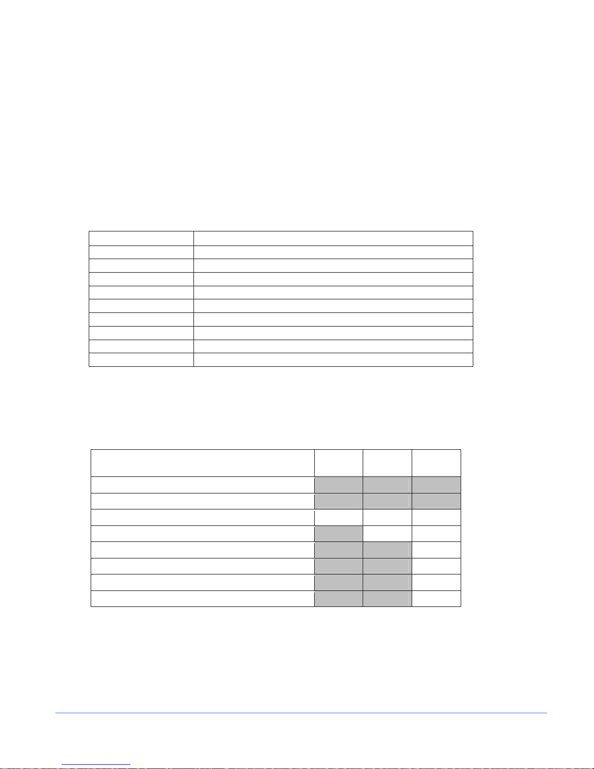
Video Formats Supported
NOTE: • = Supported Standards and formats
Table 1-2. Options and Supported Video Formats
Video Formats CMN-41-S CMN-41
DVB-ASI and SMPTE-310
Analog Composite
SD-SDI • • •
HD-SDI • •
3 Gb/s-SDI •
Dual Link - YCBCR 10 Bit 4:4:4 •
Dual Link –RGB and RGB+A, 10 Bit 4:4:4. and 4:4:4:4 •
Dual Link – YCBCR and RGB, 12 Bit 4:4:4 •
CMN-41-
3GB
2 CM N-41 Ser i es Installa tion and Oper ati o n H andbook
Copyright © 2009, Harris Corporation
Page 21

Section 1 ♦ Introduction
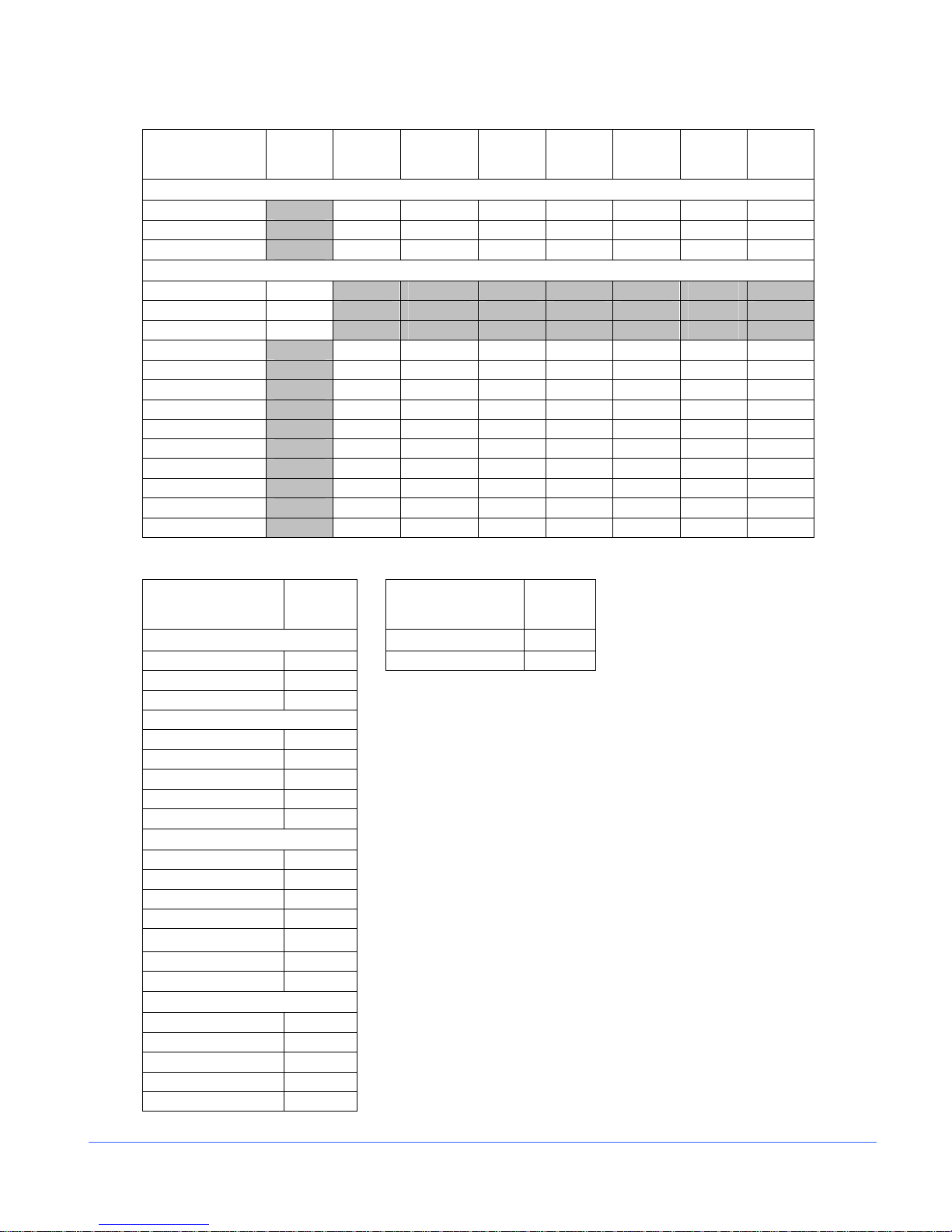
Table 1-3. 3 Gb/s Formats
10 bit
Format
1080i
1080i/60 • • • • • • •
1080i/59.94 • • • • • • •
1080i/50 • • • • • • •
1080p
1080p/60 •
1080p/59.94 •
1080p/50 •
1080p/30 • • • • • • •
1080p/29.97 • • • • • • •
1080p/25 • • • • • • •
1080p/24 • • • • • • •
1080p/23.98 • • • • • • •
1080psF/30 • • • • • • •
1080psF/29.97 • • • • • • •
1080psF/25 • • • • • • •
1080psF/24 • • • • • • •
1080psF/23.98 • • • • • • •
720p
720p/60 • • • •
720p/59.94 • • • •
720p/50 • • • •
720p/30 • • • •
720p/29.97 • • • •
720p/24 • • • •
720p/23.98 • • • •
4:2:2
YCBCR
10 bit
4:4:4
YCBCR
10 bit
4:4:4:4
YCBCR +A
10 bit
4:4:4
RGB
10 bit
4:4:4:4
RGB+A
12 bit
4:2:2
YCBCR
12 bit
4:4:4
YCBCR
12 bit
4:4:4
RGB
NOTE: Both Level A and Level B 3 Gb/s formats are supported. When a 3 Gb/s Level A signal is
detected, the standard is shown with the letter “A” appended to the format (1080p/59.94 A). When a 3
Gb/s Level B signal is detected, the standard is shown with the letter “B” appended to the format
(1080p/59.94 B).
CMN-41 Seri es In sta l la t io n an d O peration Handbook 3
Copyright © 2009, Harris Corporation
Page 22
Section 1 ♦ Introduction
Table 1-4. Dual Link Formats
10 bit
4:2:2
Format
YCBCR
1080i
1080i/60 • • • • • • •
1080i/59.94 • • • • • • •
1080i/50 • • • • • • •
1080p
1080p/60 •
1080p/59.94 •
1080p/50 •
1080p/30 • • • • • • •
1080p/29.97 • • • • • • •
1080p/25 • • • • • • •
1080p/24 • • • • • • •
1080p/23.98 • • • • • • •
1080psF/30 • • • • • • •
1080psF/29.97 • • • • • • •
1080psF/25 • • • • • • •
1080psF/24 • • • • • • •
1080psF/23.98 • • • • • • •
10 bit
4:4:4
YCBCR
10 bit
4:4:4:4
YCBCR +A
10 bit
4:4:4
RGB
10 bit
4:4:4:4
RGB+A
12 bit
4:2:2
YCBCR
12 bit
4:4:4
YCBCR
12 bit
4:4:4
RGB
Table 1-5. HD Formats Table 1-6. SD Formats
10 bit
4:2:2
YC
BCR
1080i
1080I/60 • 625/50 •
1080I/59.94 •
1080I/50 •
1080p
1080P/30 •
1080P/29.97 •
1080P/25 •
1080P/24 •
1080P/23.98 •
720p
720p/60 •
720p/59.94 •
720p/50 •
720p/30 •
720p/29.97 •
720p/24 •
720p/23.98 •
Segmented Frame
1080P/30sF •
1080P/29.97sF •
1080P/25sF •
1080P/24sF •
1080P/23.98sF •
10 bit
4:2:2
YCBCR
525/59.94
•
4 CM N-41 Ser i es Installa tion and Oper ati o n H andbook
Copyright © 2009, Harris Corporation
Page 23
Section 1 ♦ Introduction
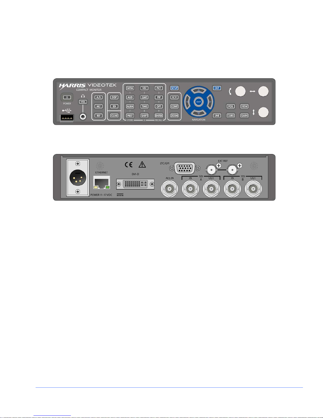
Front and Back Panels
The CMN-41 front and back panels are illustrated in Figure 1-1.
Figure 1-1. CMN-41 Front and Back Panels
Front Pa ne l
Back Panel
CMN-41 Seri es In sta l la t io n an d O peration Handbook 5
Copyright © 2009, Harris Corporation
Page 24

Section 1 ♦ Introduction
Service and Support
For service and support, telephone the Harris Customer Service Department at
1-888-534-8246. If the problem cannot be resolved over the telephone and the
instrument must be shipped to Harris for service or repair:
• Obtain a Return Authorization (RA) number from the Harris Customer Service
Department.
• Attach a tag to the unit with the following information:
− Your company name, address, and telephone number
− The name of the contact person at your company
− The RA number
− The unit serial number
− An explanation of the problem
• To prevent shipping damage, pack the unit the same way Harris had packed it. If
possible, use the original packing materials in the original shipping container.
• Ship the unit to the following location:
Harris Corporation
Videotek Test and Measurement
243 Shoemaker Road
Pottstown, PA 19464-6433
Attn: RA xxxx (where xxxx is the RA number)
Email: BCDService@harris.com
6 CM N-41 Ser i es Installa tion and Oper ati o n H andbook
Copyright © 2009, Harris Corporation
Page 25

Section 2 ♦ Installation
This section provides information about inspecting, installing, and configuring the
CMN-41.
Inspecting the Shipment
Before installing the CMN-41, inspect the box and the contents. Report any damage to
the shipper, and then telephone the Harris Corporation Customer Service Department
(see “Service and Support” on page 6).
NOTE: Refer to the enclosed packing sheet for the latest list of items that are supplied with the
unit.
The box contains the following:
• One CMN-41 rasterizer
• One CMN-41 Installation and Operation Handbook on CD
• One 75Ω terminator
• One detachable power cord
• One power supply assembly
• One breakout connector (for LTC/GPI)
Save the box and packing material for any future shipping requirements.
CMN-41 Seri es In sta l la t io n an d O peration Handbook 7
Copyright © 2009, Harris Corporation
Page 26
Section 2 ♦ Installation
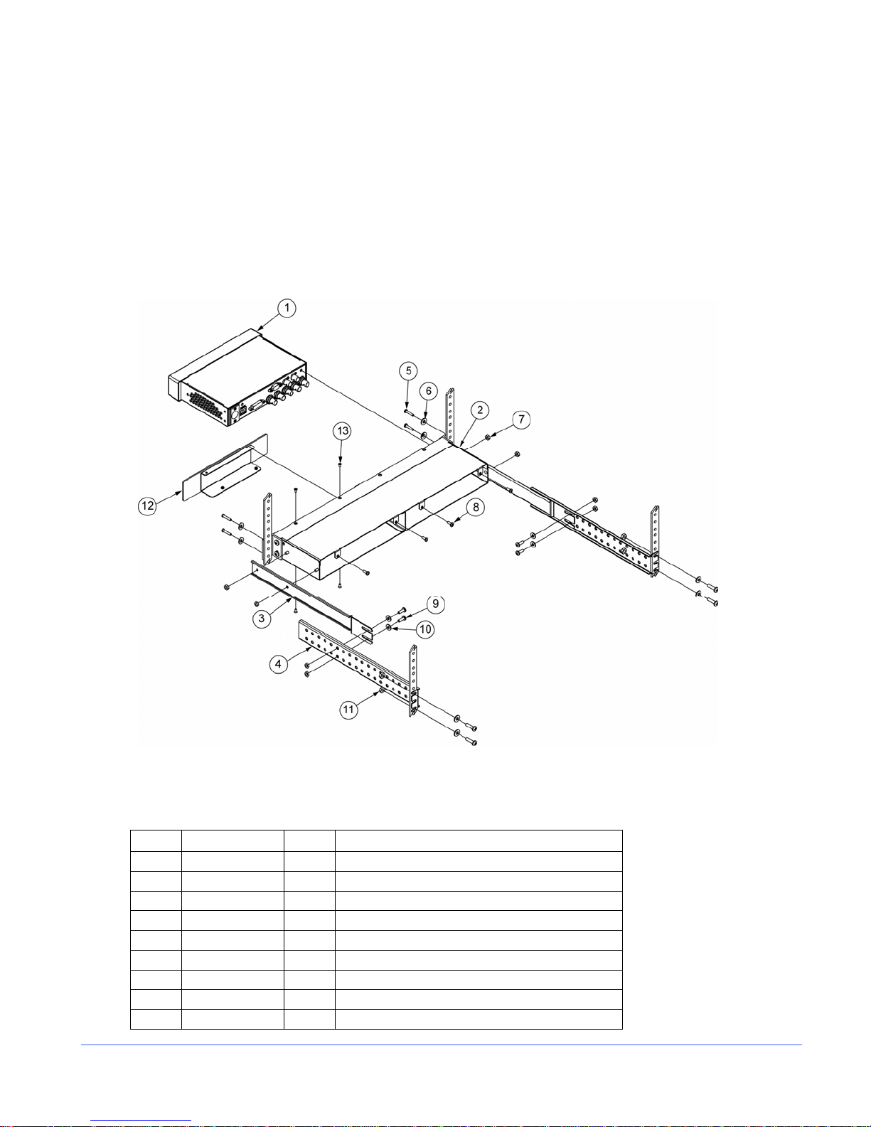
Rack Mounting the CMN-41
When selecting the permanent mounting location for the CMN-41, make sure that the
flow of air to the ventilation holes on the top and sides of the chassis is not obstructed.
Rack mounting the CMN-41 is illustrated in Figure 2-1 for the DRT-4 rack mount
case. Table 2-1 lists the parts required to rack mount the CMN-41 into the DRT-4 rack
mount case.
Figure 2-1. Mounting the CMN-41 in a Rack Using the DRT-4
NOTE: Although only one CMN-41 unit is shown in Table 2-1, two CMN-41 units may be mounted into a
DRT-4 rack case.
Table 2-1. Parts Required to Rack Mount the CMN-41 Using the DRT-4
Key Item Number Qty Description
1 — A/R CMN-41 unit
2 866080 1 DRT-4 rack tray
3 832072 2 Metal extension mount
4 832070 2 Metal extension bracket
5 831030 8 #10-32×¾-in. Phillips head screws
6 831019 4 Nylon washer, rack mount
7 831119 8 #8–32 kep nuts
8 831131 4 #8–32×3/8-in. Phillips head screws (CMN mtg)
9 831064 4 #8–32×½-in. Phillips head screws
8 C MN-41 Series Inst a llation and O peration Handbook
Copyright © 2009, Harris Corporation
Page 27

Section 2 ♦ Installation
Table 2-1. Parts Required to Rack Mount the CMN-41 Using the DRT-4
Key Item Number Qty Description
10 831118 8 #10 flat washers
11 831030 4 #10-32×¾-in. Phillips head screws
866073 FP BLK-4 (optional cover plate)
12 832131 1 DRT-4 metal blank panel
13 831136 4 #4–40×¼ self-tapping Phillips head screws
DRT-4 Rack Mount Installa tion
1. Install the extension bracket mounts (ITEM 3) to both sides of the chassis
(ITEM 2) using four #8–32 kep nuts (ITEM 7)
2. Install the assembled unit in a rack using #10–32×¾-in Phillips head screws (ITEM
5) and washers (ITEM 6) through the chassis front mounting ears, as shown.
3. Hold the extension bracket (ITEM 4) in place on each side of the chassis, and
loosely install #8–32×½-in. Phillips head screws (ITEM 9), #10 flat washers
(ITEM 10), and #8–32 kep nuts (ITEM 7) into the holes that align with the slots in
the metal extension mount (ITEM 3).
4. Install the #10-32×¾-in. Phillips head screws (ITEM 5), #10 flat washers (ITEM
10), and #10-32×¾-in. Phillips head screws (ITEM 11) through the rack rails and
the appropriate slots in the back of the metal extension bracket (ITEM 4), and then
tighten them.
5. Tighten the remaining hardware that joins the bracket pairs (ITEM 3 and ITEM 4).
6. Using 3/8-in. Phillips head screws (ITEM 8), secure the CMN-41 unit to the back of
the DRT-4 rack case.
7. If desired, install the optional BLK-4 cover plate:
• Slide the metal cover plate (ITEM 12) into the desired side of the DRT-4 rack.
• Using 4 self tapping screws (ITEM 13), secure the cover plate into the DRC-3
rack.
8. The installation is complete.
CMN-41 Seri es In sta l la t io n an d O peration Handbook 9
Copyright © 2009, Harris Corporation
Page 28
Section 2 ♦ Installation
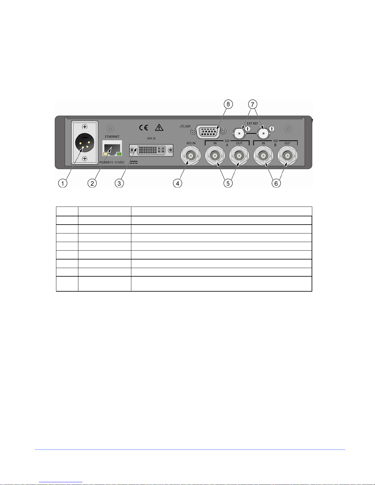
Connecting the CMN-41
The back panel connectors are illustrated in Figure 2-2, and the function of each
connector is described in Table 2-2.
Figure 2-2. CMN-41 Back Panel Connectors
Table 2-2. Description of Back Panel Connectors
Key Label Description
1 PWR 11-17VDC Power connector
2 ETHERNET RJ45, female, 10/100Base-T Ethernet connector*
3 DVI-D DVI connector for external monitor
4 AES IN AES input BNC connector
5 SDI A Input and output BNC connectors for SDI A
6 SDI B Input and output BNC connectors for SDI B
7 EXT REF External reference input and loop through
8 LTC/GPI
*See “Pinouts” starting on page 109 for the connections.
15-pin, high-density, female, D-sub connector for LTC/GPI/TALLY
input*
10 C MN-41 Series In sta l la ti o n an d O peration Handbook
Copyright © 2009, Harris Corporation
Page 29
Section 2 ♦ Installation
Ethernet Setup
NOTE: The Ethernet default settings for the CMN-41 are as follows:
IP: 192.0.0.100
Subnet Mask: 255.255.255.192
Gateway: 255.255.255.255
1. Prior to performing the CMN-41 network configuration, obtain TCP/IP addresses
from the system administrator or the Internet service provider (ISP). These
addresses are a static IP address (unless using Dynamic Host Configuration
Protocol [DHCP]), a subnet mask, and an optional gateway IP.
Be sure to record all addresses in the spaces provided below. The gateway address
is not needed unless the CMN-41 is routed to an outside network.
Record the addresses:
CMN-41 Interface Static IP Address
CMN-41 Interface Subnet Mask
Gateway IP Address
2. Identify a host PC to configure and test the CMN-41.
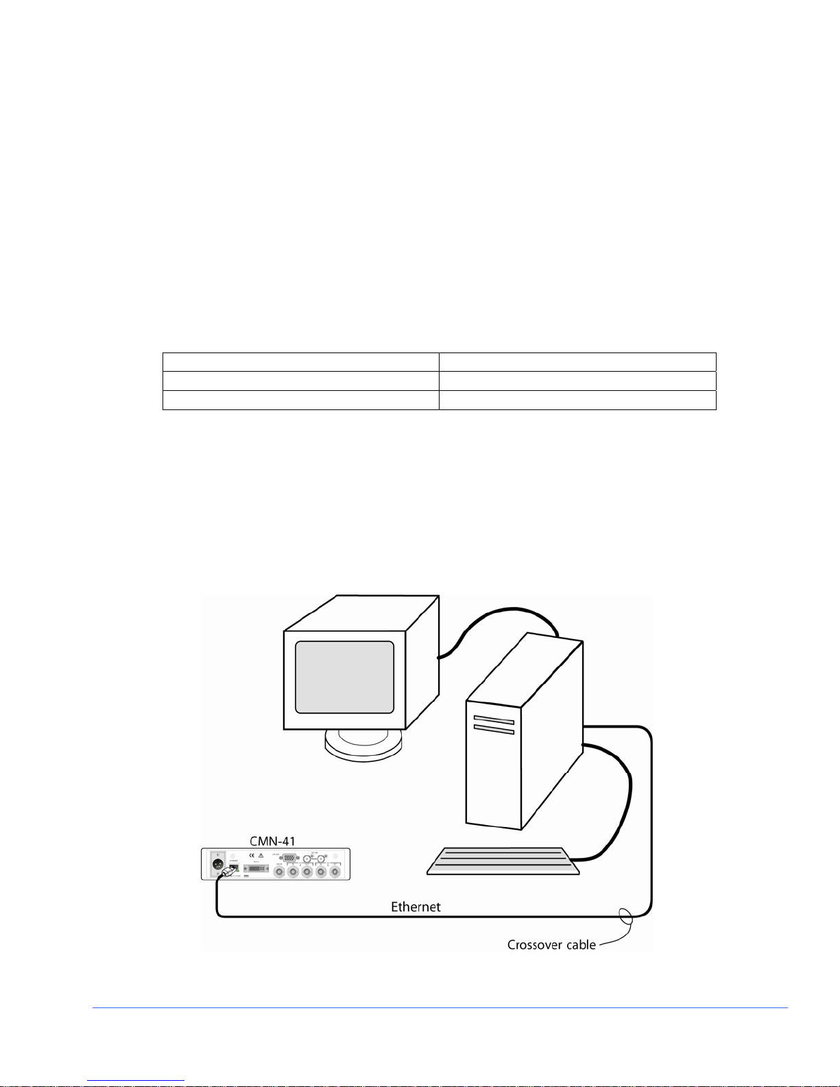
3. Choose a dedicated PC connection or network connection method:
• For a dedicated PC connection, connect the host PC with a network card to the
“ENET” connector on the back panel of the CMN-41, using a CAT5 crossover
cable (not included). See Figure 2-3.
Figure 2-3. CMN-41 Dedicated PC Connection
CMN-41 Seri es In sta l la t io n an d O peration Handbook 11
Copyright © 2009, Harris Corporation
Page 30
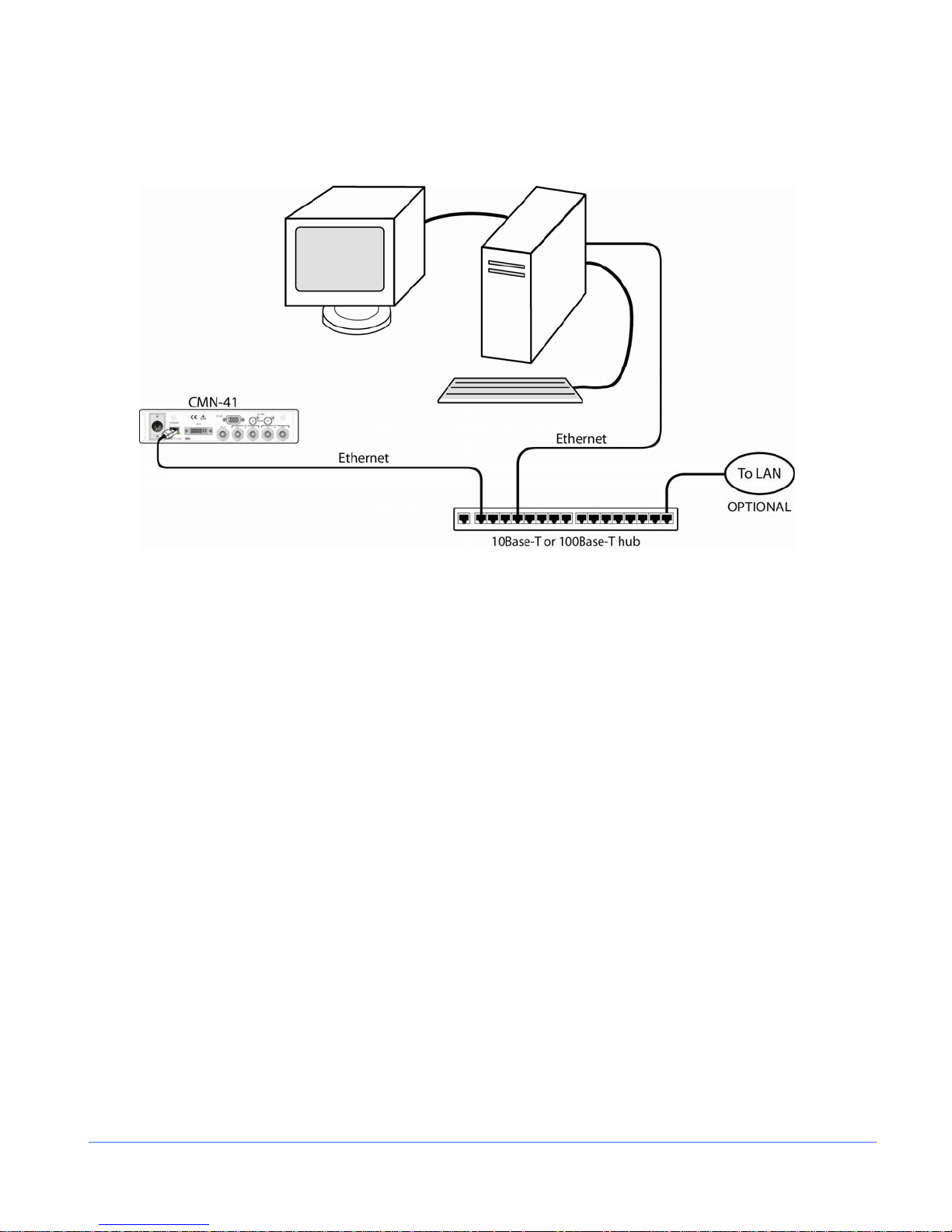
Section 2 ♦ Installation
• For a network connection, connect the network hub to the back panel of the
CMN-41 using a CAT5 network cable (not included). See Figure 2-4.
Figure 2-4. CMN-41 Network PC Connection
4. Set up an Ethernet configuration as follows:
a) Press the SETUP button on the CMN-41 front panel.
b) Press the Up/Down arrow button to highlight the Unit Configuration Setup
menu, and then press the ENTER button to enter the submenu.
c) Press the Up/Down arrow button until the IP CONFIGURATION selection
option is highlighted.
d) Press the ENTER button or Left/Right arrow button to enter the Ethernet
Config selection option.
e) If using DHCP:
• Press the Left/Right arrow button to highlight DHCP.
• Press the Up/Down arrow button to toggle the state to ON.
• Press the Left/Right arrow button to highlight ACCEPT, and then press the
ENTER button.
The IP Address is retrieved from the DHCP server and placed under the
appropriate submenu.
f) If not using DHCP:
• Press the Left/Right arrow button to select IP ADDRESS.
• Press the Up/Down arrow button to change the value selected, and then
press the Left/Right arrow button to highlight the next value.
12 C MN-41 Series In sta l la ti o n an d O peration Handbook
Copyright © 2009, Harris Corporation
Page 31

Section 2 ♦ Installation
• Repeat for the remainder of the IP Address, Subnet Mask, and Gateway. To
avoid conflicts, the static IP Address, Subnet Mask, and Gateway should be
obtained from the System Administrator.
g) Press the Left/Right arrow button to highlight ACCEPT, and then press
ENTER to accept the entered values.
h) Press the EXIT button to exit the submenu.
CMN-41 Seri es In sta l la t io n an d O peration Handbook 13
Copyright © 2009, Harris Corporation
Page 32

Section 2 ♦ Installation
This page is intentionally blank.
14 C MN-41 Series In sta l la ti o n an d O peration Handbook
Copyright © 2009, Harris Corporation
Page 33

Section 3 ♦ General Information
Terms
The following terms are used in this section:
• Display: The output at the DVI connector
• Full: Full-screen display of the selected input
• MLT: Overlay multi-mode operational state
Overview
The CMN-41, shown in Figure 3-1 and described in Table 3-1, can display one input
at a time, in full-screen mode. Each screen provides a user-selectable customized
display of waveform, vector, gamut, audio, picture, relative timing, or alarm functions.
NOTE: Pressing and holding certain buttons will activate menus for additional functionality. See
Table 3-1 for more information.
Types of Controls
The CMN-41 is controlled in three ways:
• Quick Controls: Controls on the front panel that adjust parameters that are
frequently used.
• Menu Settings: Shortcut menus within a function that are used to control the
parameters for the individual function.
• Global Setup Menu Settings: Setup menu parameters that affect the entire unit
(not function-specific). The Setup menu is accessed by pressing the SETUP button.
CMN-41 Seri es In sta l la t io n an d O peration Handbook 15
Copyright © 2009, Harris Corporation
Page 34

Section 3 ♦ General Information
Front Panel Controls
The front panel controls are illustrated in Figure 3-1.
Figure 3-1. CMN-41 Front Panel Controls
Most buttons and text are in a low-tally (low illumination) state; under certain
conditions, however, some buttons and text reach a high-tally (high illumination) state,
as described in Table 3-1. If a function is not operational, the associated button
illumination is OFF. The high and low tally illumination levels can be set in the High
Tally and Low Tally selection options of the Unit Configuration → Front Panel setup
menu select ion option.
NOTE: Multiple buttons may be high tally at the same time. The last control selected is the active control.
Table 3-1. CMN-41 Front Panel Controls
Key Label Description
1 POWER
2
3
4 MLT
5 REF External Reference selection button; press and release to toggle between
6 SDI
7 CLEAR
8 ALRM
9 PRST Preset selection button; press and release to enable Preset selection
10 TIME
11 SHIFT Shift selection button; press and release to use numeric keypad for direct
• Power switch button; press and release to turn unit power on
• Press and hold to turn unit power off
USB port
Headphone jack
• Multi-display or Overlay button; press and release to toggle between a
full-display and a multi-display screen
• Press and hold to access the MLT Setup menu
internal and external reference
• Data button; press and release to freeze data
• Once data is frozen, press and release to toggle between live and
frozen mode
• Clear Display selection button; press and release to clear a display
• Press and hold to access the Clear Setup menu
• Alarm selection button; press and release to switch to Alarm mode
• Press and hold to access the Alarm Setup menus
• Timing selection button; press and release to switch to Timing mode
• Press and hold to access the Timing Setup menu
parameter entry
16 CMN-41 Series In sta l la ti o n an d O peration Handbook
Copyright © 2009, Harris Corporation
Page 35

Section 3 ♦ General Information
Table 3-1. CMN-41 Front Panel Controls
Key Label Description
12 OPT
• Option selection button; press and release for the LTC or REF
waveform displays
• Press and hold to access the OPT menu
13 ENTER Press and release to accept the contents of displayed dialog boxes
14 COMP Component selection button; press and release to cycle through individual
waveform components
15 ZOOM Zoom selection button; press and release for zoom selections
16 Navigation Use to navigate menus and select selection options (see page 17 for an
explanation of how to operate the navigation items)
17 LINE Line selection button; press and release to activate Line Selection mode
18 POS Position selection button; press and release to enable controls to
horizontally or vertically adjust the contents of a WFM, LTC, or REF
waveform display
19 CURS Cursor selection button; press and release to select cursor functionality for
a waveform or vector display
20 VIEW View Adjust selection button; press and release to enable controls to scale
or adjust the position of an active display
21 GAIN Gain Control selection button; press and release to activate Gain controls
22 Up/Down
Use to move the waveform display
Arrow Knob
23 Left/Right
Use to move the waveform display
Arrow Knob
24 Curved Arrow
Use for vector, cursor, and output audio level
Knob
25 EXIT Exit selection button; press and release to leave menu function selections
26 H/V Horizontal/vertical sweep selection button; press and release to toggle
between waveform horizontal and vertical sweep
27 SETUP
• Setup button; press and release to access Setup mode
• Press and release to exit the displayed Setup menu
28 PIP
• Picture-in-picture selection button; press and release for a thumbnail
display of the current picture available with the selected input
29
• Press to select, store, or delete a selection in the Preset memory bank
• Press to enter numeric values for certain parameters (the Shift button
will be high tally to indicate that the numeric keypad is available for
direct parameter entry)
30 PICT
• Picture selection button; press and release for a picture display
• Press and hold to access the Picture Setup menu
31 GMT
• Gamut selection button; press and release for a gamut display
• Press and hold to access the Gamut Setup menu
32 VEC
• Vector selection button; press and release for a vector display
• Press and hold to access the Vector Setup menu
33 AUD
• Audio selection button; press and release for an audio display
• Press and hold to access the Audio Setup menu
34 WFM
• Waveform selection button; press and release for a waveform display
• Press and hold to access the Waveform Setup menu
35 DISP
• Display button; press and release to freeze a display
• Once a display is frozen, press and release to toggle between live and
frozen mode
36 A/B SDI input button, press to toggle between SDI input A and B
CMN-41 Seri es In sta l la t io n an d O peration Handbook 17
Copyright © 2009, Harris Corporation
Page 36

Section 3 ♦ General Information
Table 3-1. CMN-41 Front Panel Controls
Key Label Description
37 VOL
• Volume selection button; press and release to activate the curved knob
to adjust headphone audio volume
• Press and hold to access the audio channel selection matrix
Sleep Mode
To setup up Sleep mode, choose the UNIT CONFIGURATION → DISPLAY SETUP
→ SLEEP MODE selection option. This menu allows the selection of how much time
has to pass without any button presses in order for the unit to enter Sleep mode.
When entering Sleep mode, the instrument will turn off all LEDs and the display. The
instrument is still active (that is, alarms still triggered, and so forth). When exiting
Sleep mode, the instrument returns to an illuminated state.
Selecting an Input
Press the A/B Input button to select input A or B. (Input A is the default selection.)
When an input is selected, pressing the input button again will change to the new input
from the previous input. High tally indicates input A is selected.
Display Selections
The CMN-41 unit screen display shows data in either a full-screen or an overlay
display. The screen display also contains the Main Title Bar, the display, and the status
bar.
Press the MLT button to toggle between full screen or overlay display.
MLT is high tally when selected.
Full Screen Display
The Full Screen display mode shows a full-screen representation of a waveform,
picture, alarm, vector, gamut, audio, or timing display for a single input at a time.
A sample Full Screen display is shown in Figure 3-2 and described in Table 3-2.
18 CMN-41 Series In sta l la ti o n an d O peration Handbook
Copyright © 2009, Harris Corporation
Page 37

Figure 3-2. Full Screen Display
Section 3 ♦ General Information
Table 3-2. Description of Full Screen Display
Key Description
1 Main title bar
2 Specific elements of function display (waveform, vector, etc.)
3 Full screen display
4 Full screen status bar
5 Display icon area
CMN-41 Seri es In sta l la t io n an d O peration Handbook 19
Copyright © 2009, Harris Corporation
Page 38

Section 3 ♦ General Information
Overlay Display
Overlay mode is a combination of the waveform, vector, and (if desired) picture-inpicture (PIP) displays. Descriptions of these display types start on page 25.
A sample Overlay display is shown in Figure 3-3 and described in Table 3-3.
Figure 3-3. Ov erlay Display
Table 3-3. Description of Overlay Display
Key Description
1 Main title bar
2 Specific elements of function display
3 Waveform display
4 PIP display
5 Overlay status bar
6 Vector display
7 Display icon area
Each component in the Overlay display can be adjusted individually. Use the
appropriate function button (that is, WFM, VEC, or PIP) to select the display to be
adjusted. Refer to the appropriate function description sections for more information.
20 CMN-41 Series In sta l la ti o n an d O peration Handbook
Copyright © 2009, Harris Corporation
Page 39

Section 3 ♦ General Information
To move a selected display component, make sure the VIEW button is in high tally.
Use the Up/Down and Left/Right arrow knobs to move the selected display to the
desired location on the screen. Use the curved arrow knob to scale the size of the
selected display.
Main Title Bar
The main title bar is displayed at the top of the screen, and contains the Company
name, date and time, icon indictors, most current alarm (alarm background color is
yellow when active), and the model name.
Icons
Icons appear in the main title bar and are shown in a specified order (left to right).
Table 3-4 shows the icons and the condition for the appearance:
Table 3-4. Description of Icons
Icon Condition
External USB device connected
Alarm condition active
DISP or SDI data is frozen in memory. If a display is captured and in memory, DISP
overlays the icon. If SDI is captured and in memory, SDI overlays the icon. If both DISP
and SDI are captured and in memory, DISP and SDI overlay the icon.
Status Bar
A status bar is located at the bottom of each display. The status bar displays
information based on the function selected and configuration applied. See the specific
function section (Waveform, Vector, Gamut, Picture, PIP, Audio, Alarm, Timing, and
Option) for more detailed information on the status bar that is displayed.
Selecting an Internal or External Reference
Press and release the REF button to toggle between internal and external reference.
Selecting a Function
Press the appropriate function button to select Waveform, Vector, Gamut, Picture,
Picture-in-Picture, Audio, Alarm, Timing, or Option for the display. Press and hold the
function button to display the pertinent Setup menu.
NOTE: The different function operations are described in detail in Section 4.
When a button is pressed that cannot be used with a selected function (Waveform,
Vector, and so forth), the message FUNCTION NOT ALLOWED briefly appears over
the center of the screen.
CMN-41 Seri es In sta l la t io n an d O peration Handbook 21
Copyright © 2009, Harris Corporation
Page 40

Section 3 ♦ General Information
Accessing and Navigating the Setup Menu
Press the SETUP button to access the global Setup menu. Specific
function setup menus can be accessed directly by pressing and holding
the corresponding function button.
For more information on the global Setup menu, see page 64.
Use the navigation buttons or the setup position knobs to navigate the Setup menu. The
setup position knobs and navigation buttons are described in Table 3-5.
Table 3-5. Setup Position Knobs and Navigation Button Functions
Button/Knob Function
Press to exit the Setup menu.
Press to enter or exit the Setup menu.
Press to select a menu item, or open a menu or submenu.
Press to move up in a menu or submenu tree.
Press to move right to the next submenu.
Press to move out of a submenu.
Press to move down in a menu or submenu.
Rotate to set numeric values for certain parameters.
Press to set parameter to default value.
Press to use the numeric keypad for direct parameter entry. The Shift button will be
high tally to indicate that the numeric keypad is available for direct parameter entry.
Capturing a Display
The CMN-41 is capable of holding frame-captured displays in internal
memory. The DISP button is high tally when a capture is performed or
recalled. If no frame had been captured, press the DISP button to
capture the screen.
Only one captured frame can be cached in the unit at a time. The frame will remain
cached until the frame is cleared. Once the frame is frozen and the DISP button is high
tally, press the DISP button to toggle between the captured frame and the live frame.
22 CMN-41 Series In sta l la ti o n an d O peration Handbook
Copyright © 2009, Harris Corporation
Page 41

Section 3 ♦ General Information
Storing a Captured Display
While a captured frame is shown, press the STORE button to save the captured frame
to internal memory. The captured frame can be recalled at a later time by using the
RECALL button. In addition, the EXPORT selection option can be used to transfer the
display capture to a USB device via the File Navigator dialog box, or the web browser
interface can be used to access the display capture. For more information on the File
Navigator dialog box, see page 87. For more information on the web browser interface,
see page 99.
Recalling a Captured Display
While a captured frame is shown, press the RECALL button to recall a captured frame
from internal memory via the File Navigator dialog box. For more information on the
File Navigator dialog box, see page 87.
Clearing a Captured Display
While a captured frame is shown, press the CLEAR button to clear the frozen frame.
Once the frozen frame is cleared, a new frame capture can be performed.
Capturing Display Data
The CMN-41 can hold frame-captured information in internal memory.
The SDI button is high tally when a capture is performed or recalled.
If no data had been captured, press the SDI button to capture the data. The SDI button
is high tally when information is captured. Only one captured data can be cached in the
unit at a time. The data will remain cached until the data is cleared. Once the data is
frozen and the SDI button is high tally, press the SDI button to toggle between
displaying the captured data and the live data.
When selecting a different function, the SDI button will change according to the
current configuration of that frame (that is, if the captured data in the cache is displayed
or not displayed). When returning to a function that already contains and displays the
cached captured data, the SDI button reaches a high-tally state.
SDI is deselected if the SDI or the CLEAR button is pressed.
Storing Captured Data
While captured data is shown, press the STORE button to save the captured data to
internal memory. The captured data can be recalled at a later time by using the
RECALL button. In addition, the EXPORT selection option can be used to transfer the
captured data to a USB device via the File Navigator dialog box, or the web browser
interface can be used to access the display capture. For more information on the File
Navigator dialog box, see page 87. For more information on the web browser interface,
see page 99.
CMN-41 Seri es In sta l la t io n an d O peration Handbook 23
Copyright © 2009, Harris Corporation
Page 42

Section 3 ♦ General Information
Recalling Captured Data
While captured data is shown, press the RECALL button to recall captured data from
internal memory via the File Navigator dialog box. For more information on the File
Navigator dialog box, see page 87.
Clearing Captured Data
Press the CLEAR button to clear the frozen information in the frame. Once the frozen
data is cleared from the frame, a new data capture can be performed.
24 CMN-41 Series In sta l la ti o n an d O peration Handbook
Copyright © 2009, Harris Corporation
Page 43

Section 4 ♦ Operating the CMN-41
Overview
In the CMN-41, certain buttons function differently, depending on the parameters
selected. Once the function is determined, more detailed settings can be configured.
This section focuses on the operation of the CMN-41 according to the selected display.
See Figure 3-1 on page 16 for information about the location of the buttons described
in this section. See Section 3 for general information on how the CMN-41 operates.
Waveform Display
Press and release the WFM function button to access the Waveform
display. The waveform graticule scales, units of measure, and critical
amplitude limits change according to the video format displayed.
Press and hold the WFM function button to access the Waveform Setup menu selection
options. (Press the SETUP or the EXIT button to clear the Waveform Setup menu.)
Table 4-1 shows the Units of Measure that appear for a video format. Table 4-2 lists
the critical amplitude limits, which are indicated on the screen by special dashed lines
for the video formats that can be displayed.
Table 4-1. Video Formats and Units of Measure
Video Format Unit of Measure
High Definition and Standard Definition 525 and
625
High Definition 59.94 or 60, or Standard Definition
525 displayed as composite (NTSC)
High Definition 50 or Standard Definition 625
displayed as composite (PAL)
Table 4-2. Video Formats and Critical Amplitude Limits
Video Format Critical Amplitude Limits
High Definition and Standard Definition 0.6125 V = upper 75% chroma limit
Standard Definition 525 as Composite (NTSC) 7.5 IRE – black level
Volts or Percent (Selectable)
IRE
Units or Volts (Selectable)
0.525 V = 75% luminance limit
0.350 V = 50% point; black for color difference
channels
0.0875 V = lower 75% chroma limit
A waveform display is shown in Figure 4- 1 and described in Table 4-3. The figure
shows the location for the various waveform display fields.
CMN-41 Seri es In sta l la t io n an d O peration Handbook 25
Copyright © 2009, Harris Corporation
Page 44

Section 4 ♦ Operating the CM N-4 1
Figure 4-1. Waveform Display Diagram
Table 4-3. Description of Waveform Display Diagram
Field
Identifier
Field information Nomenclature
1 Input Displays selected input (A or B)
2 Standard Displays the Line Rate/Frame Rate; this is selected in the
Video Setup menu
3 Format Displayed as YCBCR, RGB, YRGB, or Composite
(CMPST); this can be selected in the Display/Format
selection options of the Waveform Setup menu
4 Filter For component displayed as Flat, Low Pass, or Bowtie
For composite displayed as Flat, Low Pass, Chroma, or
Flat and Low Pass
This can be selected in the Composite or Component Filter
selection options of the Waveform Setup menu
5 Line select information Shown as Line number with the ODD or EVEN field (odd or
even field will only show for interlaced Video Formats)
6 Reference Displays the reference as INT, EXT (toggled by pressing
the REF button)
7 Scale Indicates the major graticule indications for time
8 Time cursor readout Displays the time cursor as TIME and the selected
numerical value followed by the unit or measure (µs)
9 Amplitude cursor readout Displays the amplitude cursor as AMP and the selected
numerical value, followed by the unit or measure (mV,
units, or IRE)
10 Gain Displays the selected gain; Gain ranges are x0.5 to x15.0
26 CMN-41 Series In sta l la ti o n an d O peration Handbook
Copyright © 2009, Harris Corporation
Page 45

Section 4 ♦ Operating the CM N-4 1
Table 4-3. Description of Waveform Display Diagram
Field
Identifier
11 Zoom Displays Zoom when enabled; blank when Zoom is
12 WFM graticule Shows the WFM RGB, YCBCR, or Composite graticule; the
Field information Nomenclature
disabled
graticule is dependent upon the Video format, Zoom, and
scale selections
Graticules are configured by selecting the Video Input Format along with the
appropriate Waveform Setup scale adjustment (Units, %, or Volts). The scales can also
change when the ZOOM button is pressed.
Figure 4-2 to Figure 4-4 illustrate some waveform graticules with the critical
amplitude limits for the video formats that can be displayed by the CMN-41. The
critical amplitude limits are indicated on the screen by special dashed lines.
Figure 4-2. RGB and YCBCR Graticule
CMN-41 Seri es In sta l la t io n an d O peration Handbook 27
Copyright © 2009, Harris Corporation
Page 46

Section 4 ♦ Operating the CM N-4 1
Figure 4-3. RGB and YCBCR Zoom 0 mV Graticule
Figure 4-4. RGB and YCBCR Zoom 700 mV Graticule
Waveform Front Panel Selections
The following buttons directly affect the waveform display.
Moving the Wavef orm
Move the Waveform display relative to the graticule by selecting the
POS button, and then using the Left and Right arrow knobs (for
horizontal movement) and the Up and Down knob (for vertical
movement).
Scroll the Left/Right (horizontal direction) or Up/Down (vertical direction) arrow knob
to move the waveform in the particular direction. Press the Left/Right or Up/Down
arrow knobs to center the waveform.
Selecting Horizontal or Vertical Sweep
Press the H/V button to select one of the horizontal sweep modes or to
toggle between horizontal and vertical sweep modes.
28 CMN-41 Series In sta l la ti o n an d O peration Handbook
Copyright © 2009, Harris Corporation
Page 47

Figure 4-5. Sample H/V Display
Section 4 ♦ Operating the CM N-4 1
Setting the Vertical and Horizontal Amplification Range
Gain is used to set the range of the vertical and horizontal amplification
in the video signal. The standard gain in the video signal is x1.
The CMN-41 can be used to set the gain amplification in the video signal using the
Gain button. The vertical gain setting appears in the upper-left portion of the waveform
display, as shown in Figure 4-6. The horizontal gain setting appears in the upper-right
portion of the waveform display.
Vertical Amplification
Press and release the Gain button, and then use the Up/Down arrow knob to scroll
through the gain selection range, or press the Up/Down arrow knob to select one of the
preset gain selections (x0.5, x1.0, x2.5, x5.0).
Horizontal Amplification
Press and release the Gain button, and then press the Left/Right arrow knob to cycle
through the horizontal gain sequence of x1.0, x5.0, x10.0, and back to x1.0. When
vertical sweep is selected, the gain sequence changes to x1.0, x5.0, and x25.0.
CMN-41 Seri es In sta l la t io n an d O peration Handbook 29
Copyright © 2009, Harris Corporation
Page 48

Section 4 ♦ Operating the CM N-4 1
Figure 4-6. Establishing the Gain
Selecting Components
Press and release the COMP button to step through single or multiple
components in a signal.
When multiple components are selected, use the H/V button to toggle between 1H and
1V. With only one component selected, press the H/V button to toggle between 1H and
1V, or 2H and 2V.
Selecting Display Options
Press and release the ZOOM button to cycle through these display options:
• ZOOM positioned on the 0 IRE, 0 mV, or 0% graticule line
• ZOOM positioned on the 100 IRE or 700 mV, or 100% graticule
line
• Normal view
At each zoom position, the graticule scale and waveform displays expand to provide
more resolution around the zoom point.
Placing the Waveform Display in Line Select Mode
Press and release the LINE button to enable the monitoring of a single
line of a video signal. To view a line in Line Select mode:
1. Press the LINE button to place the selected waveform display in Line Select mode.
At the bottom-center of the display, the Line number and the Odd or Even field
appear, as shown in Figure 4-7.
30 CMN-41 Series In sta l la ti o n an d O peration Handbook
Copyright © 2009, Harris Corporation
Page 49

Section 4 ♦ Operating the CM N-4 1
Figure 4-7. Establishing Line Select
NOTE: In a Progressive (p) format, odd and even selections are not available.
9. Press the Up/Down arrow knob to alternate between Odd and Even fields.
10. Rotate the Up/Down arrow knob to select the line to be displayed, or press the
SHIFT function button to use the numeric keypad to enter the line number.
Waveform Cursor Selections
Cursor indications are available for precise measurement of waveform
voltage and waveform time. The cursor indications appear at the top of
the display. The Time Cursor indication is identified as TIME, and the
Amplitude Cursor indication is identified as AMP, as shown in Figure
4-8.
Figure 4-8. Establishing Cursor Select
To enable the time and amplitude cursor indications, press and release the CURS
button. Press the CURS button again to disable the cursor indications.
• To select the TIME cursor, press the Left/Right arrow knob to select the REF
cursor. Press the arrow knob again to select the DELTA cursor. Press the arrow
knob again to select both cursors.
• To select the AMP cursor, press the Up/Down arrow knob to select the REF cursor.
Press the arrow knob again to select the DELTA cursor. Press the arrow knob again
to select both cursors.
In all cases, the TIME and AMP numeric readout at the top of the display indicates the
difference between the REF and DELTA cursors. The active cursor (REF, DELTA, or
both) is shown with small arrows at both ends of the cursor.
CMN-41 Seri es In sta l la t io n an d O peration Handbook 31
Copyright © 2009, Harris Corporation
Page 50

Section 4 ♦ Operating the CM N-4 1
To exit the cursor function while leaving the cursors active, press the WFM button or
select another mode in the display (that is, LINE, GAIN, or POS).
Waveform Setup Menu
Press and hold the WFM function button to access the Waveform Setup menu. For
more information on the Waveform Setup menu, see page 66. For descriptions of
Waveform Setup menu selection options, see page 75.
Vector Display
Press and release the VEC function button to access the vector display.
A vector display is shown in Figure 4-9 and described in Table 4-4.
This illustrates the general location for the various vector fields.
Press and hold the VEC function button to access the Vector Setup menu selection
options. (Press the SETUP or the EXIT button to clear the Vector Setup menu.)
Figure 4-9. Ve ctor Di spla y Diagram
32 CMN-41 Series In sta l la ti o n an d O peration Handbook
Copyright © 2009, Harris Corporation
Page 51

Section 4 ♦ Operating the CM N-4 1
Table 4-4. Description of Vector Display Diagram
Field
Identifier Field Information Nomenclature
1 Input Displays selected input (A or B)
2 Standard Shown as line rate/frame rate; this can be selected in the
Video Setup menu
3 Format Displayed as CbCr; this can be selected in the Vector Setup
menu
4 Line select information Shown as Line and the number with the Odd or Even field
(Odd or even Field will only show for certain video formats)
5 Reference Displays the reference as INT, EXT (toggled by pressing the
REF button)
6 Vector graticule Shown as Vector graticule
7 Phase cursor readout Displays phase cursor as VEC PHASE and number in
degrees
8 Gain Displays the selected gain; gain ranges are x0.5 to x15.0
9 Zoom Shown as Zoom (when enabled); blank when disabled
Not shown Vector Standard Displayed as 75%, 100%, or 75% + 100%; this is set in
Standard selection option of the Vector Setup menu
Graticules are configured by selecting the Video Input Format along with the
appropriate Vector Setup standard.
Some graticule scales are illustrated in Figure 4-10 to Figure 4-17.
Figure 4-10. Vector NTSC Graticule
CMN-41 Seri es In sta l la t io n an d O peration Handbook 33
Copyright © 2009, Harris Corporation
Page 52

Section 4 ♦ Operating the CM N-4 1
Figure 4-11. Vector NTSC Zoom Upper Left
Figure 4-12. Vector NTSC Zoom Upper Right
34 CMN-41 Series In sta l la ti o n an d O peration Handbook
Copyright © 2009, Harris Corporation
Page 53

Section 4 ♦ Operating the CM N-4 1
Figure 4-13. Vector NTSC Zoom Lower Right
Figure 4-14. Vector NTSC Zoom Lower Left
CMN-41 Seri es In sta l la t io n an d O peration Handbook 35
Copyright © 2009, Harris Corporation
Page 54

Section 4 ♦ Operating the CM N-4 1
Figure 4-15. Vector PAL Zoom Center
Figure 4-16. Vector SD with I/Q
36 CMN-41 Series In sta l la ti o n an d O peration Handbook
Copyright © 2009, Harris Corporation
Page 55

Section 4 ♦ Operating the CM N-4 1
Figure 4-17. Vector HD 75% + 100% Graticule
Vector Front Panel Selections
The following buttons directly affect the vector display.
Setting the Vector Gain
Gain is used to set the range of the amplification in the video signal. The standard gain
in the vector is x1.0. The CMN-41 can be used to set the gain amplification in the
video signal using the Gain button. The gain setting appears in the upper-left portion of
the vector display, as shown in Figure 4-18.
Press and release the Gain button, and then use the Up/Down arrow
knob to scroll through the gain selection range, or press the Up/Down
arrow knob to select one of the preset gain selections (x0.5, x1.0, x2.5,
x5.0).
Figure 4-18. Establishing the Vector Gain
CMN-41 Seri es In sta l la t io n an d O peration Handbook 37
Copyright © 2009, Harris Corporation
Page 56

Section 4 ♦ Operating the CM N-4 1
Setting Display Options
Press the ZOOM button to cycle through these display views:
• Expand the center
• Expand the upper-left quadrant
• Expand the upper-right quadrant
• Expand the lower-right quadrant
• Expand the lower-left quadrant
• Normal view
Vector Zoom is helpful when an increased resolution of phase or saturation is required.
Placing the Vector Display in Line Select Mode
Pressing the LINE button enables monitoring of a single line of a video
signal. This enables Line Select to monitor individual areas of the entire
image. To view a line in Line Select mode:
1. Press the LINE button to place the selected vector display in Line Select mode. At
the bottom-center of the display, the Line number and the Odd or Even field
appear, as shown in Figure 4-19.
Figure 4-19. Establishing Line Select
NOTE: In a Progressive (p) format, odd and even selection is not available.
2. Press the Up/Down arrow knob to alternate between Odd and Even fields.
3. Rotate the Up/Down arrow knob to select the line to be displayed, or press the
SHIFT function button to use the numeric keypad to enter the line number.
Vector Cursor Selections
Cursors are available for precise measurement of vector phase (in
degrees). Press the CURS button on the front panel to enable the cursors
for the selected display. The Phase Cursor indications are shown in
Figure 4-20.
38 CMN-41 Series In sta l la ti o n an d O peration Handbook
Copyright © 2009, Harris Corporation
Page 57

Section 4 ♦ Operating the CM N-4 1
Figure 4-20. Establishing Cursor Select
To enable the Phase cursors, press and release the CURS button. Press the CURS
button again to disable the cursor information.
When the cursor is selected, the Phase indication appears at the top of the display. Next
to the Phase indication is a numeric readout that indicates the difference between the
REF and DELTA lines. The active cursor (REF, DELTA, or both) is shown with small
arrows at the outer end of the line.
To select a cursor line for control:
1. Press the curved arrow knob to select the REF or DELTA line to control. The REF
line is the solid line, and the DELTA line is the dotted line.
2. Rotate the curved arrow knob to move the REF or DELTA line to the desired
locat ion.
3. Press the curved arrow knob for the next cursor. Rotate the knob to move the cursor
to the desired location.
4. Press the curved arrow knob a third time to control both the REF and DELTA lines.
5. Repeat as necessary.
Once the cursors are no longer necessary, press and release the CURS button to disable
the Phase cursor selection.
To exit the cursor function while leaving the cursor active, press the VEC function
button or select another mode (that is, LINE, GAIN, or POS)
Vector Setup Menu
Press and hold the VEC function button to access the Vector Setup menu. For more
information on the Vector Setup menu, see page 67. For descriptions of Vector Setup
menu selection options, see page 77.
Gamut Display
A constant setback in video production is the difference between the allowable ranges
of dissimilar component and composite color spaces. Combinations of values that are
within the range of a color-difference component video system produce signal
amplitudes outside the ranges when the signal is transcoded to composite or RGB color
space.
CMN-41 Seri es In sta l la t io n an d O peration Handbook 39
Copyright © 2009, Harris Corporation
Page 58

Section 4 ♦ Operating the CM N-4 1
Press and release the GMT function button to access the Gamut display.
The Gamut displays show RGB limits or composite video limits.
Press and hold the GMT function button to access the Gamut Setup menu selection
options. (Press the SETUP or the EXIT button to clear the Gamut Setup menu.)
Both Gamut displays illustrate what colors are causing illegal excursions and whether
these digressions are above or below the allowable limits. The inputs are shown as an
encoded display with gamut alarms. The displays show RGB and composite video
limits.
Vector excursion marks are shown in the gamut display. The excursion marks help to
visualize the minimum/maximum value of a 100% color bar signal. The position of the
excursion marks depend on the selected Video Format selection from the Video Setup
menu.
A gamut display diagram is shown in Figure 4-21 and described in Table 4-5. The
diagram illustrates the general location for the various gamut fields.
Figure 4-21. Gamut Display Diagram
Table 4-5. Description of Gamut Display Diagram
Field
Identifier
1 Input Displays selected input (A or B)
2 Standard Displays the Line Rate/Frame Rate [1080i/59.94]; this is
3 Format Displayed as Cps and RGB; this can be selected in the
40 CMN-41 Series In sta l la ti o n an d O peration Handbook
Field Information Nomenclature
selected in the Video Setup menu
Gamut Setup menu
Copyright © 2009, Harris Corporation
Page 59

Section 4 ♦ Operating the CM N-4 1
Table 4-5. Description of Gamut Display Diagram
Field
Identifier
4 Line select information Shown as Line and the number with the Odd or Even field
5 Reference Displays the reference as INT, EXT (toggled by pressing
6 Lower luma alarm limit
7 Upper luma alarm limit
8 Luma alarm limit Displays Luma when Composite is selected; this field is
9 Lower chroma alarm limit Displayed as Lower = xxx yy
10 Upper chroma alarm limit Displayed as Upper = xxx yy
11 Chroma alarm limits Displayed as RGB (for RGB or Single Color) and PEAK (for
12 Luma/Mono bar graticule Shows the Luma/Mono bar graticule
13 Zoom Zoom when enabled; blank when disabled
14 Gamut Graticule Composite or RGB Gamut graticule
Field Information Nomenclature
(when applicable)
the REF button)
Displayed as Lower = xxx yy; xxx is the Luma lower
(Com posite only)
(Com posite only)
threshold setting and yy is determined by the format (IRE
for NTSC and Units or mV for PAL)
Displayed as Upper = xxx yy; xxx is the Luma upper
threshold setting and yy is determined by the format (IRE
for NTSC and Units or mV for PAL)
blank when Single Color or RGB is selected
• For RGB xxx is the s the RGB Gamut lower threshold
setting, and yy as units
• For Composite, xxx is the Peak lower threshold setting
• In Composite, yy is determined by the format (IRE for
NTSC and Units for PAL)
• For RGB, xxx is the RGB Gamut upper threshold setting
and yy is shown as mV
• For Composite, xxx is the Peak upper threshold setting
In Composite, yy is determined by the format (IRE for
NTSC and Units or mV for PAL)
Composite)
Composite Gamut
The graticule for the composite gamut vector, as shown in Figure 4-22 and described
in Table 4-6, is two concentric circles with other identifiers. When setting the upper
and lower limits, the upper and lower gamut rings represent the values set from the
threshold values of the appropriate format. To move the gamut rings, set the
ALARMS → VIDEO → GAMUT → PEAK GAMUT UPPER (or LOWER) →
THRESHOLD 525/59.94 or THRESHOLD 625/50 selection option. To move the luma
bar limits, set the ALARMS → VIDEO → GAMUT → LUM GAMUT UPPER (or
LOWER) → THRESHOLD 525/59.94 or THRESHOLD 625/50 selection option. The
outer circle (the upper gamut alarm limit) represents the highest allowable amplitude in
standard composite units (that is, IRE for NTSC and units for PAL). The inner circle
(the lower gamut alarm limit) represents the lowest allowable amplitude. The rings turn
red when the alarm is enabled and the values exceed the threshold setting.
The other identifiers are radials that extend at the angle of the designated color. These
six lines follow the same displacement as the vector display. Note that since the PAL
display is derived solely from component information, there are not two phases for
PAL signals. The +V phase is used (making the vectors look similar to NTSC).
CMN-41 Seri es In sta l la t io n an d O peration Handbook 41
Copyright © 2009, Harris Corporation
Page 60

Section 4 ♦ Operating the CM N-4 1
NOTE: There is an alarm persistence of two seconds associated with any alarm indication. After an alarm
has cleared, two seconds will pass before the gamut alarm indicator returns to normal.
Figure 4-22. Composite Gamut Vector Display Graticule Markings
Table 4-6. Description of Composite Gamut Indicators
Key Indicator Description
1 Lower Gamut Ring The lower gamut ring indicates the Gamut alarm Peak Lower limit.
When the Gamut alarm is enabled and the Peak Lower limit is
exceeded, the lower gamut ring turns red.
2 Upper Gamut Ring The upper gamut ring indicates the Gamut alarm Peak Upper
limit. When the Gamut alarm Peak Upper limit is exceeded, the
upper gamut ring turns red.
3 Vector Excursion Mark The excursion marks help to visualize the minimum/maximum
value of 100% color bars.
4 Luma Upper Limit Line The Luma Upper Limit Line indicates the Gamut alarm Luma
Upper limit. When the Gamut alarm is enabled, and the Luma
Upper limit is exceeded, the luma upper limit line and LUMA turn
red.
5 Luma Lower Limit Line The Luma Lower Limit Line indicates the Gamut alarm Luma
Lower limit. When the Gamut alarm is enabled, and the Luma
lower limit is exceeded, the Luma Lower Limit line and LUMA turn
red.
RGB Gamut Display
When setting the upper and lower limits, the upper and lower gamut rings represent the
threshold values. To move the gamut rings, set the ALARMS → VIDEO →
GAMUT → RGB GAMUT UPPER (or LOWER) → THRESHOLD selection option.
The RGB Gamut Display, shown in Figure 4-23 and described in Table 4-7, is similar
to the Composite Gamut Display. The RGB Gamut vector displays video amplitudes
42 CMN-41 Series In sta l la ti o n an d O peration Handbook
Copyright © 2009, Harris Corporation
Page 61

Section 4 ♦ Operating the CM N-4 1
(which are in mV) in a polar format to represent color information. The rings turn red
when the alarm is enabled and the values exceed the threshold setting.
Each R, G, and B pixel is plotted using amplitude and phase. The amplitude is derived
from the R, G, B component. The phase is derived from the CB CR information of the
digital signal. The pixels can be plotted as a single color or as each component color
(see Table 5-8 on page 67). Unlike the composite Gamut vector, which plots two
points per pixel, the RGB Gamut vector plots three points. Also, signals with no color
content are displayed on a separate bar graph labeled Mono.
The RGB graticule is nearly identical to the composite graticule. The only differences are
• Amplitudes are displayed in mV rather than IRE or UNITS.
• The radials representing color vectors are 60° apart since they are displayed in a
component color space.
• Mono bar graph is for monochrome.
NOTE: There is an alarm persistence of two seconds associated with any alarm indication. After an alarm
has cleared, two seconds will pass before the gamut indicator returns to normal.
Figure 4-23. Component (RGB) Gamut Vector Display Graticule Markings
Table 4-7. Description of RGB Gamut Indicators
Key Indicator Description
1 Lower Gamut Ring The lower gamut ring indicates the RGB Gamut alarm Lower limit.
2 Upper Gamut Ring The upper gamut ring indicates the RGB Gamut alarm Upper limit.
3 Vector Excursion Mark The excursion marks help to visualize the minimum/maximum
4 Mono Mono indicates the monochrome of the RGB signal. There is no
CMN-41 Seri es In sta l la t io n an d O peration Handbook 43
When the RGB Gamut alarm is enabled and the Lower limit is
exceeded, the lower gamut ring turns red.
When the RGB Gamut alarm is enabled, and the Upper limit is
exceeded, the upper gamut ring turns red.
values of 100% color bars.
alarm associated with Mono.
Copyright © 2009, Harris Corporation
Page 62

Section 4 ♦ Operating the CM N-4 1
Placing the Gamut Display in Line Select Mode
Press the LINE button to enable monitoring of a single line of a video
signal. This enables Line Select to monitor individual lines of the entire
image.
To view a line in Line Select mode:
1. Press the LINE button to place the selected Gamut display in Line Select mode. At
the bottom of the display, the Line number and Odd or Even field appear, as shown
in Figu re 4-24.
Figure 4-24. Establishing Line Select
NOTE: In a Progressive (p) format, Odd and Even selections are not available.
2. Press the Up/Down arrow knob to alternate between the Odd and Even fields for
interlaced formats.
3. Rotate the Up/Down arrow knob to select the line to be displayed.
Setting Display Options
Press and release the ZOOM button to cycle through the displays of the
Composite or RGB gamut graticule:
• Expand the center
• Expand the upper-left quadrant
• Expand the upper-right quadrant
• Expand the lower-right quadrant
• Expand the lower-left quadrant
• Normal view
Gamut Setup Menu
Press and hold the GMT function button to access the Gamut Setup menu. For more
information on the global Gamut Setup menu, see page 67. For descriptions of Gamut
Setup menu selection options, see page 78.
Picture Display
The Picture Display is used to show the picture of the selected input.
Press and release the PICT function button to display the picture. A
Picture display diagram is shown in Figure 4-25 and described in Table
4-8. Only one picture can be displayed.
44 CMN-41 Series In sta l la ti o n an d O peration Handbook
Copyright © 2009, Harris Corporation
Page 63

Section 4 ♦ Operating the CM N-4 1
Press and hold the PICT button to access the Picture Setup menu. (Press the SETUP or
the EXIT button to clear the Picture Setup menu.)
NOTE: Pictures can be used as thumbnails. For more information, see page 77.
Figure 4-25. Picture Display D iagram
Table 4-8. Description of Picture Display Diagram
Field
Identifier
1 Input Displays selected input (A or B)
2 Standard Displays the line rate/frame rate; select the Standard in the
3 Line select information Shown as Line and the number with the Odd or Even field
4 Aspect ratio Displays the selected aspect ratio; select the aspect ratio in
5 Picture Displays picture of the selected video input
6 Timecode Displays location of the timecode information when timecode
Field Information Nomenclature
Video Setup menu
(when applicable)
the Unit Configuration Setup → Display Setup selection
option
is enabled
The picture display changes according to the aspect ratio and anamorphic selections in
the global Setup menu. A picture display diagram, shown as the left drawing in Figure
4-26, shows the 4:3 display with a 16:9 source. Also, the picture to the right in Figure
4-26 shows a 4:3 display with a 4:3 source.
CMN-41 Seri es In sta l la t io n an d O peration Handbook 45
Copyright © 2009, Harris Corporation
Page 64

Section 4 ♦ Operating the CM N-4 1
Figure 4-26. Aspect Ratio Source Diagram
Placing the Picture in Line Select Mode
To enable Line Select mode:
1. Press the LINE button to place the selected Picture display in Line Select mode. A
cursor appears on the selected line, as shown in Figure 4-24.
Figure 4-27. Establishing Line Select
NOTE: In a Progressive (p) format, Odd and Even selections are not available.
2. Press the Up/Down arrow knob to alternate between the Odd and Even fields for
interlaced formats.
3. Rotate the Up/Down arrow knob to select the line to be displayed.
Picture Setup Menu
Press and hold the PICT function button to access the Picture Setup menu. For more
information on the global Picture Setup menu, see page 67. For descriptions of Picture
Setup menu selection options, see page 77.
PIP Display
The Picture-In-Picture (PIP) function shows a “thumbnail” of the selected input’s
picture display, with the selected function display information appearing in the
background. The PIP function is available with the waveform, vector, gamut, audio,
alarm, time, and options functions.
While in the active display, press and release the PIP function button to
enable the picture-in-picture display.
46 CMN-41 Series In sta l la ti o n an d O peration Handbook
Copyright © 2009, Harris Corporation
Page 65

Section 4 ♦ Operating the CM N-4 1
Figure 4-28 shows the PIP function enabled in Overlay Display mode, along with the
waveform and vector displays.
Figure 4-28. Sample PIP Display
Moving a PIP
To move a PIP, make sure the PIP function button and the VIEW button are in high
tally. Use the Up/Down and Left/Right arrow knobs to reposition the PIP on the
display.
Scaling a PIP
To scale a PIP display’s size, make sure the PIP function button and the VIEW button
are in high tally. Use the curved arrow knob to resize the PIP on the display.
Removing a PIP
To remove a PIP from the display, make sure the PIP function button is in high tally,
and then press the PIP function button. The display disappears from the screen.
Audio Display
Press and release the AUD function button to display the audio display.
The CMN-41 accepts one AES/EBU and up to four groups of embedded
audio inputs. Any two input channels can be selected to be monitored on
the headphone output.
Press and hold the AUD function button to access Audio Setup menu selection options.
CMN-41 Seri es In sta l la t io n an d O peration Handbook 47
Copyright © 2009, Harris Corporation
Page 66

Section 4 ♦ Operating the CM N-4 1
Configure the audio display type and parameters using the Audio → Channel selection
options. Audio can be displayed as one of the following:
• One two-channel bar graph with one Lissajous and one Phase bar
• Two two-channel bar graphs (for a total of four channels) with two Lissajous and
two Phase bars
• Three two-channel bar graphs (for a total of six channels) with three Phase bars or
CineSound 5.1 with two Phase bars
• Four two-channel bar graphs (for a total of eight channels) with four Phase bars or
CineSound 5.1+AUX, 6.1, or 7.1 with up to three phase bars
• Eight two-channel bar graphs (for a total of sixteen channels) with eight Phase bars
Lissajous can be selected as Soundstage or X-Y displays.
Input assignments, scaling, input levels, and response can also be modified using the
Audio Setup menu.
Audio Scales
The Vertical audio graticule scales change according to the selections made in the
Audio → Meter Setup → Scale selection options. The Scale selection options are as
follows:
• Type I • DIN 45406
• Type IIA • dBFS
• Type IIB • Zero Ref dBFS
• Type I + 8 • Custom dBFS
• Nordic
• Custom dB
Vertical Audio Displa ys
Vertical Audio display diagrams are shown in Figure 4-29 to Figure 4-32, and
described in Table 4-9 to Table 4-12. The Vertical audio graticule scales change
according to the scale selections made in the Setup menu.
48 CMN-41 Series In sta l la ti o n an d O peration Handbook
Copyright © 2009, Harris Corporation
Page 67

Section 4 ♦ Operating the CM N-4 1
Figure 4-29. Two Bar Graph Display with Lissajous Diagram
Table 4-9. Description of Two Bar Graph Display with Lissajous Diagram
Field
Identifier
Field Information Nomenclature
1 Input Displays selected input (A or B)
2 Status Displays audio type as Mute, AES, or Embedded
Displays audio clip or mute alarm indicators
3 Channel Number Shown as 1-16 (AES is 1-2 and Embedded is 1-16)
4 Device Displays labels for lissajous, bar graphs, and headphone
outputs
5 Lissajous Display Lissajous of bar graph 1 with labels for R, L, and the
number of the meter being monitored (for example, M-1)
6 Zoom Zoom when enabled; blank when disabled
7 Scale Selection Displays the selected meter scale: Type I, Type IIa, Type
IIb, Type I + 8, Nordic, DIN 45406, dBFS, Zero REF dBFS,
Custom dB, and Custom dBFS
8 Level Markers Shows peak levels for the signal; this can be adjusted in
the Audio → Meter Setup selection options
9 Meter Response Displays the selected meter response: VU, Peak, True
Peak, VU + Peak, VU + True Peak, Custom
10 Audio Graticule (with
meter labels)
Shown as stereo pairs (L1, R1), SMPTE 320M, or custom
label
11 Phase Bar Phase Meter of bar graph 1
CMN-41 Seri es In sta l la t io n an d O peration Handbook 49
Copyright © 2009, Harris Corporation
Page 68

Section 4 ♦ Operating the CM N-4 1
Figure 4-30. Four Bar Graph with Lissajous Display Diagram
Table 4-10. Description of Four Bar Graph with Lissajous Display Diagram
Field
Identifier
Field Information Nomenclature
1 Input Displays selected input (A or B)
2 Status Displays audio type as Mute, AES, or Embedded
Displays audio clip or mute alarm indicators
3 Channel Number Shown as 1-16 (AES is 1-2 and Embedded is 1-16)
4 Device Displays labels for lissajous, bar graphs, and headphone
outputs
5 Lissajous Display (2) Lissajous of bar graph 2 with labels for R, L, and the
number of the meter being monitored (for example, M-2)
6 Lissajous Display (1) Lissajous of bar graph 1 with labels for R, L, and the
number of the meter being monitored (for example, M-1)
7 Zoom Zoom (when enabled); blank when disabled
8 Scale Selection Displays the selected meter scale: Type I, Type IIa, Type
IIb, Type I + 8, Nordic, DIN 45406, dBFS, Zero REF dBFS,
Custom dB, and Custom dBFS
9 Level Markers Shows peak and reference levels for the signal; this can be
adjusted in the Audio → Meter Setup selection options
10 Meter Response Displays selected meter response: VU, Peak, True Peak,
VU + Peak, VU + True Peak, Custom
11 Audio Graticule (with
Shown as L1, R1, L2, and R2 (or Custom label)
meter labels)
12 Phase Bar (1) Phase Meter of bar graph 1
13 Phase Bar (2) Phase Meter of bar graph 2
50 CMN-41 Series In sta l la ti o n an d O peration Handbook
Copyright © 2009, Harris Corporation
Page 69

Section 4 ♦ Operating the CM N-4 1
Figure 4-31. Six Bar Graph Display Diagram
Tab le 4- 11. Des cription of Six Ba r Grap h D ispl ay Diagram
Field
Identifier
Field Information Nomenclature
1 Input Displays selected input (A or B)
2 Status Displays audio type as Mute, AES, or Embedded
Displays audio clip or mute alarm indicators
3 Phase Bar (2) Phase Meter of bar graph 2
4 Channel Number Shown as 1-16 (AES is 1-2 and Embedded is 1-16)
5 Device Displays labels for lissajous, bar graphs, and headphone
outputs
6 Phase Bar (3) Phase Meter of bar graph 3
7 Level Markers Shows peak and reference levels for the signal; this can be
adjusted in the Audio → Meter Setup selection options
8 Zoom Zoom (when enabled); blank when disabled
9 Scale Selection Displays the selected meter scale: Type I, Type IIa, Type
IIb, Type I + 8, Nordic, DIN 45406, dBFS, Zero REF dBFS,
Custom dB, and Custom dBFS
10 Meter Response Displays the selected meter response: VU, Peak, True
Peak, VU + Peak, VU + True Peak, Custom
11 Audio Graticule (with
Shown as L1, R1, L2, R2, L3, and R3 (or Custom label)
meter labels)
12 Phase Bar (1) Phase Meter of bar graph 1
CMN-41 Seri es In sta l la t io n an d O peration Handbook 51
Copyright © 2009, Harris Corporation
Page 70

Section 4 ♦ Operating the CM N-4 1
Figure 4-32. Eight Bar Graph Display Diagram
Table 4-12. Description of Eight Bar Graph Display Diagram
Field
Identifier
Field Information Nomenclature
1 Input Displays selected input (A or B)
2 Status Displays audio type as Mute, AES, or Embedded
Displays audio clip or mute alarm indicators
3 Channel Number Shown as 1-16 (AES is 1-2 and Embedded is 1-16)
4 Device Displays labels for lissajous, bar graphs, and headphone
outputs
5 Phase Bar (3) Phase Meter of bar graph 3
6 Phase Bar (4) Phase Meter of bar graph 4
7 Level Meters Shows peak and reference levels for the signal; this can be
adjusted in the Audio → Meter Setup selection options
8 Zoom Zoom when enabled; blank when disabled
9 Scale Selection Displays the selected meter scale: Type I, Type IIa, Type
IIb, Type I + 8, Nordic, DIN 45406, dBFS, Zero REF dBFS,
Custom dB, and Custom dBFS
10 Meter Response Displays selected meter response: VU, Peak, True Peak,
VU + Peak, VU + True Peak, Custom
11 Audio Graticule (with
meter labels)
Shown as L1, R1, L2, R2, L3, R3, L4, and R4 (or Custom
label)
12 Phase Bar (1) Phase Meter of bar graph 1
13 Phase Bar (2) Phase Meter of bar graph 2
52 CMN-41 Series In sta l la ti o n an d O peration Handbook
Copyright © 2009, Harris Corporation
Page 71

Section 4 ♦ Operating the CM N-4 1
Figure 4-33. Sixteen Bar Graph Display Diagram
Table 4-13. Description of Sixteen Bar Graph Display Diagram
Field
Identifier
Field Information Nomenclature
1 Input Displays selected input (A or B)
2 Status Displays audio type as Mute, AES, or Embedded
Displays audio clip or mute alarm indicators
3 Channel Number Shown as 1-16 (AES is 1-2 and Embedded is 1-16)
4 Device Displays labels for lissajous, bar graphs, and headphone
outputs
5 Phase Bar (3) Phase Meter of bar graph 3
6 Phase Bar (4) Phase Meter of bar graph 4
7 Phase Bar (5) Phase Meter of bar graph 5
8 Phase Bar (6) Phase Meter of bar graph 6
9 Phase Bar (7) Phase Meter of bar graph 7
10 Phase Bar (8) Phase Meter of bar graph 8
11 Level Markers Shows peak and reference levels for the signal; this can be
adjusted in the Audio → Meter Setup selection options
12 Zoom Zoom when enabled; blank when disabled
13 Scale Selection Displays the selected meter scale: Type I, Type IIa, Type
IIb, Type I + 8, Nordic, DIN 45406, dBFS, Zero REF dBFS,
Custom dB, and Custom dBFS
14 Meter Response Displays selected meter response: VU, Peak, True Peak,
VU + Peak, VU + True Peak, Custom
15 Audio Graticule (with
meter labels)
Shown as L1, R1, L2, R2, L3, R3, L4, R4, L5, R5, L6, R6,
L7, R7, L8, or R8 (or Custom label)
CMN-41 Seri es In sta l la t io n an d O peration Handbook 53
Copyright © 2009, Harris Corporation
Page 72

Section 4 ♦ Operating the CM N-4 1
Table 4-13. Description of Sixteen Bar Graph Display Diagram
Field
Identifier
16 Phase Bar (1) Phase Meter of bar graph 1
17 Phase Bar (2) Phase Meter of bar graph 2
Field Information Nomenclature
Expan din g th e Aud i o Di s play
Press the ZOOM button to access the audio zoom feature. The range of
the zoom is dependent on the selections made in the ZOOM CENTER
and ZOOM RANGE menu. Press and hold the ZOOM button to access
this menu.
• Zoom Ce nter: Adjustable from +20 dB to –60 dB in 1 dB steps. The default is the
Reference Level setting. The zoom center adjustment is restricted by Audio Scale,
Reference Level, and Zoom Range selections.
• Zoom Ra nge : Adjustable from 4 dB to 20 dB in 2 dB steps. The default is 10 dB.
The Zoom Range adjustment is restricted by Audio Scale, Reference Level, and
Zoom Center selections.
NOTE: Zoom must be enabled to view the new adjustments.
Audio Mapping
The Audio Mapping matrix is used to assign any audio input to a meter and/or
headphone output. See page 74 for more information.
Audio Setup
Press and hold the AUD button to access the global Audio Setup menu. For more
information on the global Audio Setup menu, see page 68. For descriptions of Audio
Setup menu selection options, see page 80.
Alarm Display
Press and release the ALRM function button for the alarm display. Press
and hold the ALRM function button to access the Alarm Setup menu.
The default alarm display is the Alarm Log. For information on
individual alarms, see “Setting Alarms” on page 89.
Alarm Log Display
The Alarm Log display lists all the alarms, the date, time, time code, duration, and
peak value. The alarm list begins with the most recent alarm and can hold a maximum
of 100 alarms.
NOTE: The Alarm Log display is the default alarm display. The Alarm Status display is accessed via the
Alarm Setup menu.
An Alarm Log display diagram is shown in Figure 4-34 and described in Table 4-14.
The diagram illustrates the general location for the various alarm fields.
54 CMN-41 Series In sta l la ti o n an d O peration Handbook
Copyright © 2009, Harris Corporation
Page 73

Section 4 ♦ Operating the CM N-4 1
Figure 4-34. Alarm Log Display Diagram
Table 4-14. Description of Alarm Log Display Diagram
Field
Identifier
1 Input Displays selected input (A or B)
2 Column Labels Displays the labels # (for the number in the alarm list),
3 Alarm List Displays the list of alarms from the most recent alarm to the
*NOTE: Certain alarm parameters do not have a level measurement that can report a peak value. This is
indicated when NO RPV (No Report Peak Value) appears in the PEAK VALUE column.
Field Information Nomenclature
ALARM NAME, DATE, TIME, TIMECODE, LENGTH
(Duration), and PEAK VALUE*
last recorded alarm (a maximum of 100 alarms can be
logged)
When an alarm is first registered, it appears on the alarm display and is highlighted in
yellow. If the alarm is short term (that is, two seconds or less), the alarm text is not
highlighted after approximately two seconds. If the alarm continues longer than two
seconds, the text remains yellow and the alarm duration is incremented. When the next
alarm occurs, the previous alarm moves down one position.
The CMN-41 unit has enough memory for 100 alarms per input. When 100 different
alarm events have occurred, alarm number 100 is dropped and the most recent alarm is
tagged as 01.
Use the Up/Down navigation buttons to scroll through the alarm list
To erase the current group of alarms, press the CLEAR button.
CMN-41 Seri es In sta l la t io n an d O peration Handbook 55
Copyright © 2009, Harris Corporation
Page 74

Section 4 ♦ Operating the CM N-4 1
A GPI output dry-contact closure can be used to alert other devices when an alarm
occurs. Use the Unit Configuration → GPIO selection option (page 71) to set up the
GPI.
Alarm Status Display
The Alarm Status screen lists all the alarms, the state of each alarm setting, the current
alarm limit selection (if applicable), the current alarm duration (if applicable), and the
Accumulated alarm column.
The Alarm Status display is accessed via the Alarm Setup menu. Press and hold the
ALRM function button to access the Alarm Setup menu. Use the Up/Down navigation
buttons to scroll to the Alarm Status selection option. Press the ENT navigation button
to select the Alarm Status display.
An alarm status display diagram is shown in Figure 4-35. The diagram illustrates the
general location for the various alarm status display fields.
Figure 4-35. Alarm Status Display Di agram
The alarm status screen contains detailed information concerning alarm status
indicators. This information is separated into columns sorted by alarm name, whether
or not the alarm is enabled, lower and upper limits, thresholds, duration, and total
number of alarms. The alarm name text can appear in a colored state. The colored
states are:
• White: indicates alarm is not enabled.
• Green: indicates alarm is enabled and not exceeding alarm limits.
• Red: indicates the alarm is enabled and exceeding an alarm limits.
56 CMN-41 Series In sta l la ti o n an d O peration Handbook
Copyright © 2009, Harris Corporation
Page 75

Section 4 ♦ Operating the CM N-4 1
There is a two-second persistence for any alarm name color change.
Use the Up/Down navigation buttons to scroll through the Alarm Status list.
Video Alarms
Press and hold the ALRM button to access the Alarms Setup menu. If necessary, use
the Up/Down navigation arrows to select the Video Alarms selection option. Press the
ENT navigation button to show the available selection options.
For more information on the global Video Alarms Setup menu, see page 89. For
descriptions of Video Alarms selection options, see page 94.
Audio Alarms
Press and hold the ALRM button to access the Alarms Setup menu. If necessary, use
the Up/Down navigation arrows to select the Audio Alarms selection option. Press the
ENT navigation button to show the available selection options.
For more information on the global Audio Alarms Setup menu, see page 92. For
descriptions of Audio Alarms selection options, see page 94.
Time Code Alarms
Press and hold the ALRM button to access the Alarms Setup menu. If necessary, use
the Up/Down navigation arrows to select the Time Code Alarms selection option. Press
the ENT navigation button to show the available selection options.
For more information on the global Time Code Alarms Setup menu, see page 93. For
descriptions of Time Code Alarms selection options, see page 96.
GPI Alarms
Up to four general purpose interface alarms can be enabled. Press and hold the ALRM
button to access the Alarms Setup menu. If necessary, use the Up/Down navigation
arrows to select the GPI Alarms selection option. Press the ENT navigation button to
show the available selection options.
Tim ing Display
Press and release the TIME function button to access the Timing
display. A Timing display diagram is shown in Figure 4-36 and
described in Table 4-15. The diagram illustrates the general location for
the various Timing display fields.
Press and hold the TIME button to access the Timing Setup menu. (Press the SETUP
or the EXIT button to clear the Timing Setup menu.)
Relative timing of the inputs is compliant with SMPTE RP168.
CMN-41 Seri es In sta l la t io n an d O peration Handbook 57
Copyright © 2009, Harris Corporation
Page 76

Section 4 ♦ Operating the CM N-4 1
Figure 4-36. Ti ming Display Diagram
Table 4-15. Description of Timing Display Diagram
Field
Identifier
Field Information Nomenclature
1 Selected referenc e Displays the selected reference as REF: X where X is
ExtREF or LTC; the REF is selected in the Timing Setup
menu; also indicates reference format
2 Test Indicates the input that is being measured against the
selected reference in Field Identifier 1; also displays the
input’s line rate/frame rate (shown in Figure 4-36 as
525/59.94); selected in the Video Setup menu
3 VERT (Vertical ) The offset line in full-video lines between the reference and
the displayed video
Displays the Vertical Error Measurement as VERT: xxx
Line(s), where xxx is the measured difference between the
reference and the test input alignment of the vertical timing
(sync/TRS) in lines
4 HORZ (Horizontal) The offset time in microseconds between the reference and
the displayed video.
Displays the Horizontal Error Measurement as HORZ: yy.yyy
μs, where yy.yyy is the measured difference between the
reference and the test input alignment of the horizontal timing
(sync/TRS)
Horizontal can be yellow at 0 µs. It displays the minimum
scale resolution at 1µ and the minimum timing resolution at
0.037 µs for HD (High Definition) and 0.74 µs for SD
(Standard Definition).
5 Input Displays selected input (A or B)
6 Standard Displays the line rate/frame rate; select the Standard in the
Video Setup menu
7 REF OFFSET Displays that the zero point of the timing measurements are
offset from the REF selection by xx lines yy.yyy μs
8 Timing Graticule Shows the timing graticules, cursors, and labels
58 CMN-41 Series In sta l la ti o n an d O peration Handbook
Copyright © 2009, Harris Corporation
Page 77

Section 4 ♦ Operating the CM N-4 1
When a signal is processed, there is the potential for it to be delayed with respect to a
reference signal. The timing display is used to indicate when a video input is deviating
in time from the reference. See “Reference” on page 82 for more information on
reference selection.
The reference input indicator (REF), located in the center of the timing display,
indicates the reference-timing point for the type of signal being monitored. REF is
green when the line and µs (microseconds) cursors are all aligned. As the signal falls
out of timing alignment, the line and the µs cursors change color when it moves from
REF. When this occurs, the REF turns red. Each hash mark represents a vertical line
(top scale) and 1µs (bottom scale). Once the line or µs cursors are at the edge of the
display, arrows will appear to the right or left of the timing line.
NOTE: The Timing Display alignment accuracy is ±280 ns.
SDI Input and External Reference Formats Supported
Table 4-16. SDI Input and External Reference Formats Supported
• = Supported
SDI Input Format
525/59.94
625/50
1080i60(p30sf)
1080i59.94(p29.97sf)
1080i50(p25sf)
1080p60
1080p59.94
1080p50
1080p30
1080p29.97
1080p25
1080p24
1080p23.98
1080p24sf
1080p23.98sf
720p60
720p59.94
720p50
720p30
720p29.97
720p24
720p23.98
External Reference Format
NTSC
PAL
1080i60 (p30sf)
1080i59.94 (p29.97sf)
1080i50 (p25sf)
1080p30
1080p29.97
1080p25
1080p24
1080p23.98
1080p24sf
1080p23.98sf
720p60
720p59.94
720p50
720p30
720p29.97
720p24
• • •
• • •
• •
• • •
• • •
• • •
• • •
• • •
• • • •
• • •
• • •
• • •
• •
• •
• • • •
• • • • •
• • • •
• • • •
• • • • •
• • •
• • •
720p23.98
CMN-41 Seri es In sta l la t io n an d O peration Handbook 59
Copyright © 2009, Harris Corporation
Page 78

Section 4 ♦ Operating the CM N-4 1
Things to Remember When Using the Timing Display
1. The Timing Display measures the elapsed time between the vertical syncs of two
inputs. The elapsed time is expressed in units of microseconds and lines of the
selected input video, not of the reference.
2. When referencing a standard definition video input to an external tri-level reference
input, the line number indication in the timing display represents standard
definition video lines. If the relative timing is adjusted in high definition video
lines, it may take an adjustment of two or more lines before the line number
changes in the timing display. This is due to the high definition video lines, which
are shorter than the standard definition video lines represented by the timing
display.
3. When referencing a high definition video input to an external composite (BB)
reference input, the line number indication in the timing display represents high
definition video lines. If the relative timing is adjusted in standard definition video
lines, a single video line adjustment will cause a change of two or more lines in the
timing display. This is due to the standard definition video lines, which are longer
than the high definition video lines represented by the timing display.
4. The information of the Timing Display should not be used when captured SDI
freeze data is displayed.
Timing Setup Menu
Press and hold the TIME function button to access the Timing Setup menu. For more
information on the global Timing Setup menu, see page 70. For descriptions of Timing
selection options, see page 81.
Option Display Selections
NOTE: Only one option display can be shown at a time.
The option display shows a waveform display of the LTC or external reference inputs.
Press and release the OPT button to select the external reference or LTC
waveform display. Press and hold the OPT function button to access the
Option Setup menu. (Press the SETUP or the EXIT button to clear the
Moving the Wa ve for m
Move the Waveform display relative to the graticule by selecting the POS button, and
then using the Left and Right arrow knobs (for horizontal movement) and the Up and
Down knob (for vertical movement).
Timing Setup menu.)
Scroll the Left/Right (horizontal direction) or Up/Down (vertical direction) arrow knob
to move the waveform in the particular direction. Press the Left/Right or Up/Down
arrow knobs to center the waveform horizontally or vertically.
60 CMN-41 Series In sta l la ti o n an d O peration Handbook
Copyright © 2009, Harris Corporation
Page 79

Figure 4-37. LTC Display Diagram
Section 4 ♦ Operating the CM N-4 1
Figure 4-38. E xternal Referen ce Disp lay Di agram
CMN-41 Seri es In sta l la t io n an d O peration Handbook 61
Copyright © 2009, Harris Corporation
Page 80

Section 4 ♦ Operating the CM N-4 1
Preset Display Selections
Presets are used to store menu configurations and
display settings. A total of 99 presets can be stored in
the CMN-41.
Selecting Presets
Press and release the PRST function button to access the bank of
presets. A dialog box appears on the display screen, which shows the
Preset number. Press selection button 1 to 99 (or scroll through the
available list using the curved arrow knob) to select a preset. Press
PRST to store or overwrite an existing Preset, or press ENTER to
Recall.
Storing Presets
Press the PRST button to bring up the Presets dialog box. Press selection button 1 to 99
(or scroll through the available list using the curved arrow knob) to store the Preset.
Press the PRST button to store a new or overwrite an existing Preset.
Recalling Presets
NOTE: Information must be stored in a preset location before being recalled.
Press the PRST function button to bring up the Presets dialog box. Press selection
button 1 to 99 (or scroll through the available list using the curved arrow knob) to
recall the Preset. Press the ENTER button to recall the Preset.
If a preset does not exist for the selected number, nothing happens.
62 CMN-41 Series In sta l la ti o n an d O peration Handbook
Copyright © 2009, Harris Corporation
Page 81

Section 5 ♦ Global Setup Menu Functions
Navigating the Setup Menu
Press the SETUP button to access the global setup menu. Use the Setup position knobs
or the navigation buttons to navigate the global Setup menu selection options. The
Setup position knobs and navigation buttons are described below:
Table 5-1. Setup Position Knobs and Navigation Buttons
Item Function
Press to enter or exit the Setup menu.
Press to exit from the Setup menu.
Press to move up in the Setup menu or matrix screen.
Press to move left in the Setup menu or matrix screen.
Press to move right in the Setup menu or matrix screen.
Press to move down in the Setup m enu or matrix screen.
Rotate to set numeric values for certain parameters.
Press to set parameter to default value.
Press to select a menu selection option.
Press to use the numeric keypad for direct parameter entry. The SHIFT button will be
high tally to indicate that the numeric keypad is available for direct parameter entry.
CMN-41 Seri es In sta l la t io n an d O peration Handbook 63
Copyright © 2009, Harris Corporation
Page 82

Section 5 ♦ Global Setup Menu Func tions
Setup Menus and Alarm Tables
The following tables make up the global setup menu. An asterisk (*) is shown next to
the default menu selections. The Setup menu items are listed in Table 5-2 with their
corresponding Table and Description pages.
Table 5-2. Setup Menu Tables
Selection Table Page Description Page
Video 65 73
Audio mapping 65 74
Time code source 66 75
Waveform 66 75
Vector 67 77
Gamut 67 78
Picture 67 77
Audio 68 80
Timing 70 81
OPT 70 82
MLT 71 82
Alarms Alarm setup tables and corresponding descriptions
appear in Section 6.
Enable Dual A-B Link — —
Import/Export 71 82
Clear 71 83
Unit Configuration 71 83
64 C MN-41 Series In sta l la ti o n an d O peration Handbook
Copyright © 2009, Harris Corporation
Page 83

Section 5 ♦ Global Setup Menu Func tions
Table 5-3. Video Setup Menu
NOTE: Descriptions for these selection options start on page 73.
Selection Option Selection Option
Auto Detect *
1080i
1080i Frame Rate 60
59.94 *
50
1080p
1080p Frame Rate 60
59.94 *
50
30
29.97
25
24
23.98
1080psF
1080psF Frame Rate 30sF
29.97sF *
25sF
24sF
23.98sF
720p
720p Frame Rate 60
59.94 *
50
30
29.97
24
23.98
625/50
525/59.94
Structure Auto Detect *
10 bit YCBCR 4:2:2
10 bit YCBCR 4:4:4
10 bit RGB 4:4:4
12 bit YCBCR 4:4:4
12 bit RGB 4:4:4
12 bit YCBCR 4:2:2
Table 5-4. Audio Mapping Menu
NOTE: Descriptions for these selection options start on page 74.
Selection Option
Matrix Screen
CMN-41 Seri es In sta l la t io n an d O peration Handbook 65
Copyright © 2009, Harris Corporation
Page 84

Section 5 ♦ Global Setup Menu Func tions
Table 5-5. Time Code Source Setup Menu
NOTE: Descriptions for these selection options start on page 75.
Selection Option Selection Option
LTC *
ANC LTC
ANC DIVTC 0
ANC DVITC 1
DVITC
DVITC Line 525 Line 10 to 30 (line 14 *)
DVITC Line 625 Line 6 to 30 (line 14 *)
Table 5-6. Waveform Setup Menu
NOTE: Descriptions for these selection options start on page 75.
Selection Option Selection Option Selection Option
Display/Format YCBCR *
RGB
Composite
YCBCR + alpha
RGB + alpha
Component Filter Flat *
Low pass
Bowtie
Composite Filter Flat *
Low pass
Chroma
Flat and low pass
Component Overlay
Blanking Blank All *
Show SAV/EAV
Show All
Error Highlighting
Graticule Digital Waveform Graticule Volts *
Percent
NTSC Pedestal *
PAL Waveform Scale Volts *
Units
Intensity 0% to 100% (72% *)
Contrast 0% to 100% (31% *)
Persistence 0% to Infinite (0% *)
Attack 1% to Maximum (6% *)
66 C MN-41 Series In sta l la ti o n an d O peration Handbook
Copyright © 2009, Harris Corporation
Page 85

Section 5 ♦ Global Setup Menu Func tions
Table 5-7. Vector Setup Menu
NOTE: Descriptions for these selection options start on page 77.
Selection Option Selection Option
Standard 75%
100% *
75% + 100%
I/Q Lines
Scale to Composite
Intensity 0% to 100% (86% *)
Contrast 0% to 100% (55% *)
Persistence 0% to Infinite (0% *)
Attack 1% to Maximum
(10% *)
Table 5-8. Gamut Setup Menu
NOTE: Descriptions for these selection options start on page 78.
Selection Option Selection Option
Single color
RGB *
Composite
Data Error Persistence 0% to Infinite (0% *)
Intensity 0% to 100% (86% *)
Contrast 0% to 100% (55% *)
Persistence 0% to Infinite (0%)*
Table 5-9. Picture Setup Menu
NOTE: Descriptions for these selection options start on page 78.
Selection Option Selection Option Selection Option
Markers Center
Safe Title (Corners)
Safe Title (Box)
Safe Action (Corners)
Safe Action (Box)
Clean Aperture (Corners)
Clean Aperture (Box)
Custom (Corners)
Custom (Box)
Custom Position 1% to 49% (20% *)
Custom Length 3% to 47 (5% *)
Anamorphic
Time Code Enable
Show LTC
Position Top *
Center
Bottom
Brightness 0% to 100% (50% *)
Contrast 0% to 100% *
CMN-41 Seri es In sta l la t io n an d O peration Handbook 67
Copyright © 2009, Harris Corporation
Page 86

Section 5 ♦ Global Setup Menu Func tions
Table 5-9. Picture Setup Menu
NOTE: Descriptions for these selection options start on page 78.
Selection Option Selection Option Selection Option
Color Green *
Blue *
Red *
VBI Mask
Native
Delay Enable
H Position 1 pixel to ___ pixels
(format-dependent)
V Position 1 line to ___ lines
(format-dependent)
Gamut Error
Highlighting
Table 5-10. Audio Setup Menu
NOTE: Descriptions for these selection options start on page 80.
Selection Option Selection Option Selection Option Selection Option
2 Channels
4 Channels
6 Channels Vertical *
CineSound
8 Channels * Vertical
CineSound 5.1 + AUX *
CineSound 6.1
CineSound 7.1
16 Channels
Meter Setup Reference Level –22 dBFS to –8 dBFS
(–20 dBFS *)
Peak Program Level Type I
+1 dB to +11 dB
(+8 dB *)
Type IIa +1 dB to +11 dB
(+8 dB *)
Type IIb +1 dB to +11 dB
(+8 dB *)
Type I + 8 +1 dB to +19 dB
(+8 dB *)
Nordic +1 dB to +11 dB
(+6 dB *)
DIN 45406 +1 dB to +13 dB (+8
dB *)
dBFS +1 dB to +21 dB
(+10 dB *)
Zero Ref dBFS +1 dB to +21 dB
(+8 dB *)
Custom dBFS +1 dB to +21 dB
(+10 dB *)
Custom dB +1 dB to +21 dB
(+9 dB *)
68 C MN-41 Series In sta l la ti o n an d O peration Handbook
Copyright © 2009, Harris Corporation
Page 87

Section 5 ♦ Global Setup Menu Func tions
Table 5-10. Audio Setup Menu
NOTE: Descriptions for these selection options start on page 80.
Selection Option Selection Option Selection Option Selection Option
Scale Type I
Type IIa
Type IIb
Type I + 8
Nordic
DIN 45406
dBFS *
Zero Ref dBFS
Custom dBFS
Custom dB
Custom dBFS Top 0 dBFS to –20 dBFS
(0 dBFS *)
Custom dBFS Bottom –40 dBFS to –90
dBFS (–40 dBFS *)
Custom dB Top 0 dB to 20 dB
(10 dB *)
Custom dB Bottom –20 dB to –70 dB
(–30 dB *)
Zoom Center at Reference
Level *
Center at dB Level -60 dB to +20 dB
Zoom Range 4 dB to 20 dB (10 dB)
Peak Hold Time Off *
1 to 10 seconds
Infinite
Meter Labels Stereo Pairs *
(0 dB*)
SMPTE 320M
Custom
Custom Labels 1-8
Custom Labels 9-16
Channel (1-8) → Use
arrow keys to edit and
change characters
Channel (9-16) → Use
arrow keys to edit and
change characters
LFE Offset –10 dB
None *
CineSound Direction Outward *
Inward
Audio Markers
Position
Enable
–50 to +12 dB
(0 dB *)
CMN-41 Seri es In sta l la t io n an d O peration Handbook 69
Copyright © 2009, Harris Corporation
Page 88

Section 5 ♦ Global Setup Menu Func tions
Table 5-10. Audio Setup Menu
NOTE: Descriptions for these selection options start on page 80.
Selection Option Selection Option Selection Option Selection Option
Meter Response VU *
Peak
True Peak
VU + Peak
VU + True
Peak
Custom
Custom Attack 0 to 20 ms (0 ms *)
Custom Decay 0.3 to 5.0 seconds
(1.5 seconds *)
Lissajous Setup Persistence 0% to Infinite (0% *)
Attack 1% to Maximum
(50% *)
Automatic Gain Control
Plot Soundstage *
X-Y
Polarity Normal * Configure Phase
Bar(s)
Reverse
Damping Slow
1 to 10 (5 *)
Fast
AES Validity Bit
Table 5-11. Timing Setup Menu
NOTE: Descriptions for these selection options start on page 81.
Selection Option Selection Option
Reference External Ref *
LTC
Factory *
Offset
Set Zero Ref
Table 5-12. OPT Setup Menu
NOTE: Descriptions for these selection options start on page 82.
Selection Option
LTC *
Reference Waveform
70 C MN-41 Series In sta l la ti o n an d O peration Handbook
Copyright © 2009, Harris Corporation
Page 89

Section 5 ♦ Global Setup Menu Func tions
Table 5-13. MLT Setup Menu
NOTE: Descriptions for these selection options start on page 82.
Selection Option Selection Option
Intensity 0% to 100% (72% *)
Contrast 0% to 100% (31% *)
Persistence 0% to Infinite (0% *)
Attack 1% to Maximum
(6% *)
Table 5-14. Import/Export Setup Menu
NOTE: Descriptions for these selection options start on page 82.
Selection Option
File Navigator Screen
Table 5-15. Clear Setup Menu
NOTE: Descriptions for these selection options start on page 83.
Selection Option
DISP Captures
SDI Captures
Audio Peak Hold
Alarm Log
Alarm Error Count
Timing Zero Reference
Persistence
Table 5-16. Unit Configuration Setup Menu
NOTE: Descriptions for these selection options start on page 83.
Selection Option Selection Option Selection Op tion Select ion Op tion
Display Setup Input Color Blue
Green
Cyan
Red
Magenta
Brown
Gray
Dark Gray
Light Blue
Light Green *
Light Cyan
Light Red
Light Magenta
Yellow
White
CMN-41 Seri es In sta l la t io n an d O peration Handbook 71
Copyright © 2009, Harris Corporation
Page 90

Section 5 ♦ Global Setup Menu Func tions
Table 5-16. Unit Configuration Setup Menu
NOTE: Descriptions for these selection options start on page 83.
Selection Option Selection Option Selection Op tion Select ion Op tion
Graticule Color Blue
Green
Cyan
Red
Magenta
Brown
Gray
Dark Gray
Light Blue
Light Green
Light Cyan
Light Red
Light Magenta
Yellow
White *
Cursor Color Blue
Green
Cyan
Red
Magenta
Brown
Gray
Dark Gray
Light Blue
Light Green
Light Cyan
Light Red *
Light Magenta
Yellow
White
4:3 *
Aspect Ratio
16:9
16:10
Sleep Mode Off to 60 Minutes
Monochrome Display
Graticule Intensity 0 to 100% (50% *)
Cursor Intensity 0 to 100% *
Front Panel High Tally 35 to 100% (80% *)
Low Tally 0 to 10% (5% *)
72 C MN-41 Series In sta l la ti o n an d O peration Handbook
Copyright © 2009, Harris Corporation
Page 91

Section 5 ♦ Global Setup Menu Func tions
Table 5-16. Unit Configuration Setup Menu
NOTE: Descriptions for these selection options start on page 83.
Selection Option Selection Option Selection Op tion Select ion Op tion
GPIO Input Function Input 1 Select A
Select B
User GPI Alarm 1 *
Input 2 Select A
Select B
User GPI Alarm 2 *
Input 3 Recall Preset 1
Recall Preset 2
User GPI Alarm 3 *
Input 4 Recall Preset 3
Recall Preset 4
User GPI Alarm 4 *
Output Function Polarity Normally Open *
Norm ally Closed
Setup Follow Input A
Follow Input B
Follow Alarms *
IP Configuration Ethernet Config Screen
System Time Time Setup Screen
Show Clock *
Flash Update From
USB
Feature Upgrade From
USB
About About Screen
File Navigator Screen
File Navigator Screen
Video Setup Menu Se lect ion Opt ions
The Video Setup selection options are used to automatically or manually select the
video format reference standard for the SDI input. The format selection determines the
unit of measure and the critical amplitude limits for the input. The Video Setup
selection options are described below.
• Auto Detect: This selection option is used to automatically detect the format of the
input signal. This is the default setting.
• 1080i: This selection option is used force the unit into 1080 interlaced video mode.
• 1080i Frame Rate: This selection option is used to set up the 1080i frame rate.
Selection options are 60, 59.94, and 50. The default setting is 59.94.
• 1080p: This selection option is used to force the unit into 1080 progressive video
mode.
• 1080p Frame Rate: This selection option is used to set up the 1080p frame rate.
Selection options are 60, 59.94, 50, 30, 29.97, 25, 24, and 23.98. The default setting
is 59.94.
CMN-41 Seri es In sta l la t io n an d O peration Handbook 73
Copyright © 2009, Harris Corporation
Page 92

Section 5 ♦ Global Setup Menu Func tions
• 1080psF: This selection option is used to force the unit into 1080 progressive
segmented frame video mode.
• 1080psF Frame Rate: This selection option is used to set up the 1080psF frame
rate. Selection options are 30sF, 29.97sF, 25sF, 24sF, and 23.98sF. The default
setting is 29.97sF.
• 720p: This selection option is used to force the unit into 720 progressive video
mode.
• 720p Frame Rate: This selection option is used to set up the 720p frame rate.
Selection options are 60, 59.94, 50, 30, 29.97, 24, and 23.98. The default setting is
59.94.
• 625/50: This selection option is used force the unit into video frames with
625-line/50 Hz video mode.
• 525/59.94: This selection option is used force the unit into frames with
525-line/(60*1000/1001) Hz video mode.
• Structure: This selection option is used to configure the signal handling path to a
10-bit or 12-bit RGB or YCBCR sampling structure. 12-bit modes are not available
with formats 1080p/60, 1080p/59.94, and 1080p/50. 4:4:4 and 4:2:2 are the format
rates selected with the 10-bit and 12-bit sampling structures. 4:2:2 is only available
with 12-bit YCBCR. The selection options are as follows.
• Auto Detect: The sampling structure is determined from the Video Payload
Identifier. If there is no detected VPI, a 10-bit YCBCR sampling structure will be
assumed. This is the default setting.
• 10 bit YCBCR 4:2:2: The signal handling path will be configured for a 10-bit
YCBCR mode of operation.
• 10-bit YCBCR 4:4:4: The signal handling path will be configured for a 10-bit
YCBCR mode of operation. This selection is only available for dual link and
3 Gb/s HD.
• 10-bit RGB 4:4:4: The signal handling path will be configured for a 10-bit RGB
mode of operation. This selection is only available for dual link and 3 Gb/s HD.
• 12-bit YCBCR 4:4:4: The signal handling path will be configured for a 12-bit
YCBCR mode of operation. This selection is only available for 3Gb/s HD.
• 12-bit RGB 4:4:4: The signal handling path will be configured for a 12-bit RGB
mode of operation. This selection is only available for dual link and 3 Gb/s HD.
• 12-bit YC
BCR 4:2:2: The signal handling path will be configured for a 12-bit
YCBCR mode of operation. This selection is only available for dual link and
3 Gb/s HD.
Audio Mapping Set up Menu Selection Options
The Audio Mapping matrix is used to assign the input to the meter display or
headphone output. When the Audio Mapping setup option is selected, a matrix screen
for Mute, Embedded, and AES appears (see Figure 5-1). Use the Right/Left arrow
knobs to scroll through the column selections. Use the Up/Down arrow knobs to scroll
74 C MN-41 Series In sta l la ti o n an d O peration Handbook
Copyright © 2009, Harris Corporation
Page 93

Section 5 ♦ Global Setup Menu Func tions
through individual cell selections. Press the ENT button to assign an input to a meter.
Different audio types (AES or Embedded) can be assigned to a meter or headphone
output.
Figure 5-1. Audio Mapping Matrix Display
Time Code Source Setup Menu Selection Options
The Time Code Source Menu is used to determine the Time Code Source for each
format. The CMN-41 can read LTC (Longitudinal Time Code) and DVITC (Digital
Vertical Interval Time Code) based on the format selected. The Time Code Source
menu has these selection options:
• LTC (default)
• ANC LTC
• ANC DVITC 0
• ANC DVITC 1
• DVITC: DVITC is monitored on selected lines. After DVITC is selected, adjust
the line selection in the DVITC LINE 525 or DVITC LINE 625 submenus to the
selected line. The range for DVITC LINE 525 is adjustable from Line 10 to 30, and
DVITC LINE 625 is adjustable from line 6 to 30.
For more information on displaying time code see “Time Code” on page 79.
Waveform Setup Menu Selection Options
The Waveform Setup items are described below.
• Display Format: This selection option allows a choice of display formats: YCBCR
(default), RGB, Composite, YC
the relationships between the input and display formats.
CMN-41 Seri es In sta l la t io n an d O peration Handbook 75
BCR + Alpha, and RGB + Alpha. Table 5-17 lists
Copyright © 2009, Harris Corporation
Page 94

Section 5 ♦ Global Setup Menu Func tions
Table 5-17. Input and Display Format Relationship
YC
BCR +
Alpha
Input Format YC
3Gb/s Yes Yes Yes Yes Yes
HD Yes Yes Yes Yes Yes
SD Yes Yes Yes No No
BCR RGB Composite
(10 bit only)
RGB + Al p ha
(10 bit only)
• Component Filter: Component filters are used when the waveform display format
is set to YCBCR or RGB. Filter selection options are Flat, Low Pass, and Bowtie.
• Flat: No filtering (default)
• Low Pass: Selects the Low Pass filter
• Bowtie: Checks the timing relationships between the digital components (a
bowtie test signal is required)
• Composite Filter: Composite filters are used when the waveform display format is
set to Composite. Filter selections are Flat, Low pass, Chroma, and Flat and Low
Pass.
• Flat: No filtering (default)
• Low Pass: Selects the Low Pass filter
• Chroma: Selects the Chroma filter
• Flat and Low Pa ss: Selects Flat and Low Pass filtering
• Component Overlay: When Component Overlay is selected for a single input, the
components of the input signal are displayed over each other (that is, R over G over
B in an RGB signal).
• Blanking: The blanking selections are Blank All, EAV/SAV, and Show All.
• Blank All displays only the active video of the input signal (default).
• Show EAV/SAV displays the active video and the EAV/SAV headers of the
input signal.
• Show All displays the ancillary data, EAV/SAV, and active video.
• Error Highlighting: Error highlighting changes the color of the portion of the
waveform that exceeds the alarm settings. OFF is the default. The highlighting is
dependent upon the format and gamut settings selected. The following are rules to
consider:
• Composite format with Flat filter follows the alarm settings for Gamut Peak
upper and lower. It follows the threshold settings for the alarm, even when it is
not enabled.
• Composite format with Low Pass filter fo llows the Luma Upper and Lower
thresholds.
• Component format with RGB filter will follow the RGB gamut.
• No highlighting in YCBCR.
76 C MN-41 Series In sta l la ti o n an d O peration Handbook
Copyright © 2009, Harris Corporation
Page 95

Section 5 ♦ Global Setup Menu Func tions
• Graticule: This selection option is used to select the unit of measurement in
percent or volts for the Digital Waveform Graticule, and in volts or units for the
PAL Waveform Scale.
• NTSC Pedestal: This selection option adds setup to the Composite display
(default).
• Intensity: This selection option is used to raise or lower the brightness of the
displayed waveform. The range of intensity is 0% to 100%. The default waveform
intensity is 72%.
• Contrast: This selection option is used to adjust the overall difference between the
lightest and darkest colors of the waveform. The range of contrast is 0% to 100%.
The default waveform contrast is 31%.
• Persistence: This selection option is used to determine how long a data point
(pixel) in the waveform remains on the display. The range of persistence is 0% to
Infinite. The default waveform persistence is 0%.
• Attack: Attack is the initial intensity that the data point (pixel) appears in the
display. The range of attack is 1% to Maximum. The default waveform attack is
6%.
Vector Setup Menu Selection Opt ions
The Vector Setup menu is used to select the Standard, IQ Lines, Scale to Composite,
Intensity, Contrast, Persistence, and Attack. The Vector Setup selection options are
described below.
• Standard: Standard is used to set the marks on the vector display. The marks on
the vector help to visualize the minimum/maximum value of a video signal. The
position of the excursion marks are 75% or 100% (default) for SD and HD. The
HD standard also can be selected as 75% and 100% simultaneously.
• I/Q Lines: This selection option is used to turn OFF and ON the I and Q marker
lines on the Vector Display. The default condition is OFF.
• Scale to Composite: The Scaled to Composite menu can be used to scale the SD or
HD vector to reflect a composite format. The default condition is OFF.
• Intensity: This selection option is used to raise or lower the brightness of the
displayed vector. The range of intensity is 0% to 100%. The default selection is
86%.
• Contrast: This selection option is used to adjust the overall difference between the
lightest and darkest colors of the vector. The range of contrast is 0% to 100%. The
default selection is 55%.
• Persistence: This selection option is used to determine how long a data point
(pixel) in the vector remains on the display. The range of persistence is 0% to
Infinite. The default selection is 0%.
• Attack: This selection option is used to determine the initial intensity that the data
point (pixel) appears in the display. The range of Attack is 1% to Maximum. The
default selection is 10%.
CMN-41 Seri es In sta l la t io n an d O peration Handbook 77
Copyright © 2009, Harris Corporation
Page 96

Section 5 ♦ Global Setup Menu Func tions
Gamut Setup Menu Selection Options
The Gamut Setup menu is used to change a gamut’s color plots, Data Error Persistence,
Intensity, Contrast, and Persistence. The Gamut Setup selection options are described
below.
• Single Color, RGB, Composite (Color Plot): These selection options are used to
set the color for plotting RGB pixels. The pixels can be one single color or RGB
(red, green, or blue). Multiple colors help to indicate which color of the RGB signal
moves beyond the inner and outer parameters of the gamut graticule. The default
selection is RGB.
• Data Er ror Persi s ten ce: This selection option is used to determine how long a
point of data beyond the inner and outer parameters of the gamut graticule. The
range of persistence is 0% to Infinite. The default selection is 0%.
• Intensity: This selection option is used to raise or lower the brightness of the
displayed gamut. The range of intensity is 0% to 100%. The default selection is
86%.
• Contrast: This selection option is used to adjust the overall difference between the
lightest and darkest colors of the gamut. The range of contrast is 0% to 100%. The
default selection is 55%.
• Persistence: This selection option is used to determine how long a data point
(pixel) in the Gamut remains on the display. The range of Persistence is 0% to
Infinite. The default selection is 0%.
Picture Setup Menu Selecti on O pt ions
The Picture Setup selection options are described below. The default selection is
Anamorphic.
• Markers: There are several markers available to be indicated in a picture.
• Center is equal to 50% of the picture height and 50% of the picture width.
• Safe Title is equal to 80% of the picture height and 80% of the picture width.
• Safe Action is equal to 90% of the picture height and 90% of the picture width.
• Clean Aperture shows the limits for the active pixel area. Brackets appear on
the picture or a box surrounds the picture to show these limits. The center marker
identifies the location of the center of the picture.
• Custom (Corners) and Custom (Box) allows the setup of customized markers
for a picture display.
• Custom Posit i o n is used in conjunction with the Custom Corners and Custom
Box selections. It allows the adjustment of the custom corner or box size.
• Custom Length is used in conjunction with the Custom Corners selection
option. It allows the adjustment of the corner lengths.
• Anamorphic: This selection option is used to correct the anamorphic display.
Setting the menu selection to ON changes the actual source aspect ratio to an aspect
78 C MN-41 Series In sta l la ti o n an d O peration Handbook
Copyright © 2009, Harris Corporation
Page 97

Section 5 ♦ Global Setup Menu Func tions
ratio that fills the screen (for example, SD squeezed horizontally 16×9 to 4×3 DVD
source). The anamorphic selection is not available in 16×9 source aspect ratio.
• Time Code: This selection option is used to display the time code; that is, the time
that is associated with each video frame. Time Code is keyed over the picture on
the right side. Adjacent to the Time Code, the LTC/DVITC is keyed over the
picture on the right side when Show LTC is selected. (Show LTC cannot be
activated unless ENABLE is selected.) The Position selection option is used for the
vertical placement of the time code at the top, center, and bottom (beyond safe
action areas).
• Brightness: This selection option is used to make the picture brightness lighter or
darker. The brightness range is from 0% (for the darkest picture) to 100% (for the
brightest picture). The default picture brightness is 50%.
• Contrast: This selection option is used to increase the overall difference between
the lightest and darkest colors. The contrast range is from 0% (for no difference
between the lightest and darkest colors) to 100% (for the most amount of difference
between the lightest and darkest colors). The default picture contrast is 100%.
• Color: This selection option is used to change the picture color gun selection.
When all three colors are de-selected the picture display changes to monochrome.
• Green: Green is a setup feature that is used to show the green color component
of the input video. Use the Green feature to set the Saturation and Hue by
matching the intensity of all green bars when a SMPTE split field color bar
signal is applied.
• Blue: Blue is a setup feature that is used to show the blue color component of the
input video. Use the Blue feature to set the Saturation and Hue by matching the
intensity of all blue bars when a SMPTE split field color bar signal is applied.
• Red: Red is a setup feature that is used to show the red color component of the
input video. Use the Red feature to set the Saturation and Hue by matching the
intensity of all red bars when a SMPTE split field color bar signal is applied.
• VBI Ma sk: The VBI (Vertical Blanking Interval) Mask selection option is used to
mask non-active lines. With VBI Mask set to ON, only active lines will be shown
on the picture portion of the display.
• Native: When this selection option is enabled, it displays the SD picture as a one-
for-one pixel mapping. When Native mode is not checked, the SD picture fills the
screen.
NOTE: The Native mode menu item only appears when an SD format is detected or selected.
• Delay: This selection option is used to view the horizontal and vertical blanking
areas of the video signal. Delay enables and disables the delay mode. Delay
Position displays the amount of vertical and horizontal delay. Using the Delay
position, turn the Up/Down and Right/Left knobs to position the picture. The Delay
feature is not affected by the Native mode selection.
• Gamut Error Highlighting: When Gamut Error Highlighting is selected in the
Picture setup menu, a grid pattern appears over the picture display highlighting
gamut errors. Gamut highlighting is determined by the gamut threshold settings in
the ALARMS → VIDEO ALARMS → GAMUT selection option.
CMN-41 Seri es In sta l la t io n an d O peration Handbook 79
Copyright © 2009, Harris Corporation
Page 98

Section 5 ♦ Global Setup Menu Func tions
Audio Setup Menu Select ion Options
The Audio Setup selection options are described below.
• 2 Channels: This selection option allows the display of one 2-channel bar graph
with one lissajous and one phase bar.
• 4 Channels: This selection option allows the display of two 2-channel bar graphs
(for a total of four channels) with two lissajous and two phase bars.
• 6 Channels: This selection option allows the display of three 2-channel bar graphs
(for a total of six channels) with three phase bars, or CineSound 5.1 with two phase
bars
• 8 Channels: This selection option allows the display of four 2-channel bar graphs
(for a total of eight channels) with eight phase bars; CineSound 5.1 with two phase
bars; CineSound 6.1 with two phase bars, or CineSound 7.1 with three phase bars
• 16 Channels: This selection option allows the display of eight 2-channel bar
graphs (for a total of 16 channels) with eight phase bars
• Meter Setup: This selection option is used to select the response, ballistics, and
other meter features.
• Ref Level: This selection option is used to set the reference level on the meters
for a digital signal. The range is from –8 dBFS to –22 dBFS. The default
selection is –20 dBFS. Content below this setting is green. Content above this
setting is yellow.
• Peak Program Level: This selection option is used to adjust the position of the
peak marker on an Audio meter display. Value is the number of dB above the
reference level. Content above this value is red.
• Scale: This selection option is used to determine the type of scale that appears on
the Audio meter display. Custom dBFS and Custom dB can customize the top
and bottom of the dBFS or dB scales.
• Zoom: This selection option is used to set the Zoom modes. Selections are
Center at Reference Level, Center at dB level, and Zoom Range. The Center at
dB level has a range from –60 dB to +20 dB; the default selection is 0 dB. The
Zoom range is from 4 dB to 20 dB; the default selection is 10 dB.
• Peak Hold Time : This selection option is a user-selectable duration value of Off,
1 to 10 seconds, or Infinite. The duration only applies to the hold time of the
PEAK value, not the attack or decay time. The default selection is Off.
• Meter Labels: This selection option menu is used to select the audio mapping
scheme for the selected input. Only the Vertical Bar Meter labels can be
customized. When the CineSound display is selected, the audio inputs follow a
SMPTE 320M mapping scheme. For vertical meters only, the SMPTE 320M
meter label-mapping scheme can be changed to a stereo pair-mapping scheme or
Custom Labels.
• LFE Offset: This selection option adjusts the LFE by –10 dB when enabled.
LFE Offset only occurs when CineSound is displayed.
• CineSound Direction: This selection option is used to reverse the default meter
movement for the CineSound display. The default selection for the CineSound
80 C MN-41 Series In sta l la ti o n an d O peration Handbook
Copyright © 2009, Harris Corporation
Page 99

Section 5 ♦ Global Setup Menu Func tions
direction is from the center outward. Select INWARD to reverse the meter
movement.
• Aud io Markers: This selection option is used to place adjustable markers in the
audio meters. Adjustable markers can be placed in audio meters to show specific
critical levels.
• Meter Resp o n se : This selection option is used to display the selected meter
response. Options are VU, Peak, True Peak, VU + Peak, VU + True Peak,
Loudness, Custom, Custom Attack, and Custom Decay. The default selection is
VU.
• Lissajous Setup: This selection option is used to set up the display amplitude and
phase relationships between two input signals. Options are Persistence, Attack,
AGC, and Plot.
• Persistence: This selection option is used to determine how long a data point
(pixel) remains on the display. The range of Persistence is 0% to Infinite. The
default selection is 0%.
• Attack: This selection option is the initial intensity that the data point (pixel)
appears in the display. The range of Attack is 1% to Maximum. The default
selection is 50%.
• Automatic Gain Control: This selection option is used to keep the display
visible from very small levels to very high levels.
• Plot: This selection option is used to select one of two types of Lissajous
displays. The soundstage selection displays a Lissajous that is rotated so that the
in-phase signals appear on the vertical axis and out of phase signals appear on the
horizontal axis. X-Y displays a Lissajous with the left channel mapped to the
vertical axis, and the right channel mapped to the horizontal axis.
• Configure Phase Bar(s): Phase bars are used to monitor the instantaneous phase
relationship between two channels of audio. On a vertical audio display the “+”
marking indicates a phase difference of 0°, and the “–” marking indicates a phase
difference of 180°. A properly phased stereo pair produces a phase pointer that
moves within the green zone, whereas a reversed channel produces a pointer that
moves within the red zone.
• Polarity: This selection option is used to set the phase bar polarity to Normal or
Reverse. The default selection is Normal.
• Damping: The effect of higher damping in a phase meter is to show an averaged
rather than a peak value of phase. This selection option is used to set the phase
bar damping to Fast, 1 to 10, or Slow. The default selection is 5.
• AES Validity Bit: The AES Validity Bit is used to detect pulse code modulation
(PCM) audio or non PCM audio. Non-PCM audio can include Dolby or other
digital data.
Timing Setup Menu
The Timing Setup menu is used to set the offset of the reference to the signal. The
Timing Setup selection options are described below; the default selection is Factory.
CMN-41 Seri es In sta l la t io n an d O peration Handbook 81
Copyright © 2009, Harris Corporation
Page 100

Section 5 ♦ Global Setup Menu Func tions
• Reference: This selection option is used to set the reference source.
• External REF – This selection option uses the blackburst or tri-level signal
connected to the External Reference input.
• Factory: This selection option is used to set the factory reference to 0. When
FACTORY is selected, the OFFSET field does not appear on the screen.
• Offset: This selection option Enables and displays the Offset field. The reference
offset is not applied until Set Zero Ref is selected.
• Set Zero Ref: This selection option is used to apply the current offset setting as the
zero reference point.
OPT Setup Menu Selection Options
The OPT, or Options, setup menu is used to select Longitudinal Time Code (LTC) or
Reference Waveform.
MLT Setup Menu Selection Opti ons
The MLT Setup menu is used to set up selection options for the Overlay display mode.
Selection options include Intensity, Contrast, Persistence, and Attack.
• Intensity: This selection option is used to raise or lower the brightness of the
displayed waveform and vector. The range of intensity is 0% to 100%. The default
selection is 72%.
• Contrast: This selection option is used to adjust the overall difference between the
lightest and darkest colors of the displayed waveform and vector. The range of
contrast is 0% to 100%. The default selection is 31%.
• Persistence: This selection option is used to determine how long a data point
(pixel) in the displayed waveform and vector remains on the display. The range of
persistence is 0% to Infinite. The default selection is 0%.
• Attack: Attack is the initial intensity that the data point (pixel) appears in the
display. The range of attack is 1% to Maximum. The default selection is 6%.
Alarms Set up Menu
For information on alarm setup and descriptions, see Section 6.
Import/Export Menu
The Import/Export selection options are described below.
• Import: This selection option is used to retrieve display captures saved to a USB
device via the File Navigator dialog box. For more information on the File
Navigator dialog box, see page 87.
82 C MN-41 Series In sta l la ti o n an d O peration Handbook
Copyright © 2009, Harris Corporation
 Loading...