

Page 1

®
Intraplex
NetXpress LX™ Audio IP Multiplexer
& CM-30 IP Interface Module
Installat ion & Operation Manual
NetXpress LX Multiplexer
CM-30 Common Module
MA-230 Module Adapter
Version 1
TOTAL CONTENT DELIVERY SOLUTIONS | Managing content. Delivering results.
Page 2

Intraplex® NetXpress LX & CM-30
http://www.broadcast.harris.com/servicesandsupport/productsSupport.asp
Installation & Operation Manual
Version 1, September 2010
© Copyright 2010 Harris Corporation.
All rights reserved.
Reproduction, adaptation, or translation
without prior writ te n permission is
prohibited, except as allowed under the
copyright laws.
Warranty
The information c ontained in this
document is subject to change without
notice. Harris makes no warranty of any
kind with regard to this material,
including, but not limited to, the implied
Contact Us
Harris Corporation
Intraplex Products
4393 Digital Way
Mason, OH 45040
USA
Sales: +1 513 459 3400
Fax: +1 513 701 5316
E-mail:
Web:
intraplex@harris.com
www.broadcast.harris.com
Get Support
If you have a technical question or issu e with your Intraplex
Products equipment, pleas e c heck our customer support Web
page:
warranties of m er chantability and f itness
for a particular purpose.
Harris shall not b e liable for errors
contained herein or for incidental or
consequential dam age in connection with
the furnishing, performance, or use of
this material.
Trademark Credits
AudioLink PLUS™, HD Link™,
IntraGuide
NetXpress LX™, STL PLUS
SynchroCast
®
, Intraplex®, NetXpress™,
®
, and SynchroCast3™ are
®
,
You can also call Customer Service or send non-emergency
e-mail:
● U.S., Canada, and Latin America: +1-217-222-8200 or
tsupport@harris.com
● Europe, Middle East, and Africa: +44-118-967-8100 or
Service.europe@harris.com
● Asia and Pacific Rim: +852-2776-0628 or
BCDService@harris.com
trademarks of Harris Corporation. Other
trademarks are the property of their
respective owners.
Version Date Revisions Made Section Pages Editor
1 9/20/10 Developed manual. All All LD
Page 3

No header here
Table of Contents
Section 1 – Introduction ................................................................ 1-1
1.1 Key Features .................................................................................... 1-1
1.2 Manual Use ...................................................................................... 1-1
1.3 Manual Scope ................................................................................... 1-2
1.4 Components ..................................................................................... 1-2
1.4.1 Main Equipment Shelf ............................................................................1-2
1.4.2 CM-30 IP Int e r f ace Module ......................................................................1-2
1.4.3 MA-230 Module Adapter .........................................................................1-4
1.4.4 Other Modules and Module Adapters ........................................................1-4
1.4.5 Indicator Lights .....................................................................................1-4
1.5 Web Browser User Interface .............................................................. 1-4
Section 2 – Functional Design ........................................................ 2-1
2.1 Network Concepts and Considerations ................................................. 2-1
2.1.1 MTU throughout the Network ...................................................................2-1
2.1.2 DHCP Use .............................................................................................2-1
2.1.3 Routing Table Construction .....................................................................2-1
2.1.4 WAN Port Auto-negotiation ......................................................................2-2
2.1.5 ICMP Support ........................................................................................2-2
2.1.6 IGMP Multicast ......................................................................................2-2
2.2 Streams ........................................................................................... 2-3
2.2.1 Stream Types ........................................................................................2-3
2.2.2 Stream Addressing .................................................................................2-4
2.2.3 Multicast Group Addressing .....................................................................2-4
2.2.4 Telephony .............................................................................................2-5
2.2.5 Echo Cancellation ...................................................................................2-5
2.2.6 Packetization and Overhead ....................................................................2-6
2.2.7 Packet Jitter Compensation .....................................................................2-6
2.2.8 Packet/Stream Information Calculation .....................................................2-6
2.2.9 Stream Statistics ...................................................................................2-7
2.3 System Security ............................................................................... 2-7
2.3.1 NetXpress LX Login ................................................................................2-8
2.3.2 Management Protocols on an Interface .....................................................2-8
2.3.3 IP Access List Use ..................................................................................2-8
2.3.4 SNMP Communities ................................................................................2-8
2.4 NetXpress LX QoS ............................................................................ 2-9
2.4.1 COS Levels for Stream Data ....................................................................2-9
2.4.2 TOS Byte Marking for Outbound Stream Packets .......................................2-9
2.4.3 User-Defined TOS Byte Setting for Outbound SNMP and HTTP Packets .........2-9
2.5 NetXpress LX Internal TDM Busses ..................................................... 2-9
2.5.1 Compatibility with Intraplex TDM Channe l Modules ....................................2-9
2.5.2 TDM Channel Loopbacks ....................................................................... 2-11
2.5.3 TDM Bus Mapping ................................................................................ 2-11
Harris Corporation i
Intraplex Products
Page 4

NetXpress LX & CM-30 Installation & Operati on Manual Table of Contents
Version 1, September 2010
2.6 System Time-of-Day ....................................................................... 2-12
2.7 System Timing ............................................................................... 2-12
2.7.1 Types of System Timing ....................................................................... 2-12
2.7.2 NetXpress LX Timing Scenarios ............................................................. 2-13
2.8 NetXpress LX System and FEC ......................................................... 2-17
2.9 Power ........................................................................................... 2-18
2.10 Voice Signaling .............................................................................. 2-18
2.10.1 RBS ................................................................................................... 2-18
2.10.2 CAS ................................................................................................... 2-18
2.11 Software Download ........................................................................ 2-19
2.12 Configuration Files Backup and Restoration ....................................... 2-19
2.13 Fault Detection and Reporting .......................................................... 2-19
2.13.1 Alarm Hierarchy .................................................................................. 2-20
2.13.2 Alarm History ...................................................................................... 2-20
2.13.3 SNMP Traps Use for Fault Reporting ....................................................... 2-20
Section 3 – Installation & Wiring ................................................... 3-1
3.1 Installation Preparation...................................................................... 3-1
3.1.1 Tools & Cables Required .........................................................................3-1
3.1.2 Equipment Unpacking & Inspection ..........................................................3-1
3.2 Installation ....................................................................................... 3-2
3.2.1 Shelf Installation ...................................................................................3-2
3.2.2 CM-30 Module Kit Installation ..................................................................3-2
3.2.3 Channel Module Inst allation ....................................................................3-8
3.2.4 Power Supply Installation .......................................................................3-9
3.3 Wiring & External Connections ............................................................ 3-9
3.4 Power Application ........................................................................... 3-15
Section 4 – Configuration & Operation .......................................... 4-1
4.1 Download Current Software................................................................ 4-1
4.2 Configuration Procedures ................................................................... 4-1
4.2.1 Connect and Log On to Access NetXpress LX Home Page ............................4-1
4.2.2 View System Mode .................................................................................4-2
4.2.3 Perform General Setup ...........................................................................4-2
4.3 NetXpress LX Pages ......................................................................... 4-14
4.3.1 Start at NetXpress LX Home Page .......................................................... 4-14
4.3.2 Define & Review Fault Information ......................................................... 4-16
4.3.3 Configure the System ........................................................................... 4-21
4.3.4 Configure the Network ......................................................................... 4-36
4.3.5 Configure Streams ............................................................................... 4-49
4.3.6 Check Multiplexer Performance .............................................................. 4-59
4.3.7 Set Up Security ................................................................................... 4-71
4.3.8 Send Echo Requests ............................................................................. 4-75
4.3.9 Configure CM-30 Module ...................................................................... 4-75
ii Harris Corporation
Intraplex Produc ts
Page 5

Table of Contents NetXpress LX & CM-30 Installation & Oper ation Manual
Version 1, September 2010
4.3.10 Configure Individual Modules (TDM Modules and CAMs) ............................ 4-79
Section 5 – Testing & Troubleshooting ......................................... 5-1
5.1 Testing ........................................................................................... 5-1
5.1.1 General Status Test ...............................................................................5-1
5.1.2 CM-30 Alarm Test ..................................................................................5-2
5.1.3 Ping Test ..............................................................................................5-4
5.1.4 Streams Test ........................................................................................5-4
5.2 Troubleshooting ................................................................................ 5-6
5.2.1 Channel Module Additio n ........................................................................5-6
5.2.2 Web Browser Interface ...........................................................................5-6
Section 6 – Specifications .............................................................. 6-1
6.1 Detailed Specifications ...................................................................... 6-1
6.1.1 NetXpress LX IP Multiplexer ....................................................................6-1
6.1.2 CM-30 IP Int e r f ace Module ......................................................................6-3
6.2 Notice of FCC Compliance .................................................................. 6-5
Appendix A – T1/E1-to-NetXpress LX Multiplexer Conversion ....... A-1
A.1 Installation Preparation ..................................................................... A-1
A.1.1 Equipment Unpac king & Inspection ......................................................... A-1
A.1.2 Card Slot Selection ............................................................................... A-2
A.2 IP Multiplexer Conversion Pr ocess ...................................................... A-2
A.2.1 CM-30 & MA-230 Installation into the First Multiplexer .............................. A-2
A.2.2 First CM-30 IP Interface Module Configuration .......................................... A-3
A.2.3 CM-30 & MA-230 Installation into the Second Multiplexe r .......................... A-4
A.2.4 Second CM-30 IP Interf ace M od u le Configuration ...................................... A-4
A.2.5 Configuration of Both CM-30 Modules to Work Together ............................ A-4
A.2.6 Removal of the Original Common Modules ............................................... A-6
Harris Corporation iii
Intraplex Products
Page 6

No header here
This page is left blank intentionally.
iv Harris Corporation
Intraplex Produc ts
Page 7

No header here
Section 1 – Introduction
This manual covers both the N etXpress LX IP multiplexer and the CM-30 IP interface module. The
NetXpress LX multiplexer provides convenient provision ing and managemen t tools to enhance
operational efficiency. This IP platform supports both u nicast and multicast a nd is compatible with the
Intraplex NetXpress multiplexer.
The NetXpress LX mu ltip lexer combines the tec hnology of the original NetXpress multiplexer in a
module configur a tion compatible with Intraplex T1 or E1 systems. The NetXpress LX multiplexer is
available in either a 3RU frame with cap a c ity for up to 17 application modules or a 1RU frame that can
hold five applica tion modules. This mu ltip lexer can work in a simple point-to-point an d point-tomultipoint designs and also as an “edge” device with the NetXpress m ultiplexer in large, multisite
networks.
While the CM-30 I P interf a c e m odule operates as the command module in a NetXpress LX multiplexer,
this module can also replace the netw or k interface module in an existing T1 or E1 system, conv er ting
it to IP while utilizing the existing c hassis with all its audio, voice, and data modules. With the CM-30
module, you can easily transition an existing Intr aplex T1 or E1 system to cost-effective IP
transmission.
1.1 Key Features
The NetXpress LX system’s features include
● CM-30 IP interface module, which can convert existing T1 or E1 systems to IP
● Compatibility w ith Intraplex NetXpress systems
● Wide variety of au d io, voice, and data inter face modules
● Optional echo ca ncellation for 2-wire voice circuits
● Transport of two c ontact closures in each direction
● Adjustable packet size
● Programmable jitter buffer depth
● Advanced Intraplex forw a rd error c orr ec tion
● Quality of Serv ic e ( Q oS) priority tagging
● Unidirectional or bidirectional unicast streaming
● Unidirectional multicast stream ing
● Web browser user interface
● SNMP control
● Current and prev ious software revis ion storage
● Network statistic s monitoring
● Event logging
1.2 Manual Use
This manual is th e pr im ary reference document for installin g, configuring, operatin g, a nd
troubleshootin g the NetXpress LX multiplexer and the CM-30 IP interface module. If you have
additional quest ions pertainin g to the operation of you r Intraplex system, you can contact Harris
Customer Service:
● U.S., Canada, and Latin America: +1-217-222-8200 or
● Europe, Middle East, and Af r ica : +44-118-964-8100 or
● Asia and Pacific Rim: +852-2776-0628 or
Harris Corporation 1-1
Intraplex Products
tsupport@harris.com
Service.europe@harris.com
BCDService@harris.com
Page 8
NetXpress LX & CM-30 Installation & Operati on Manual 1 – Introduction
Version 1, September 2010
1.3 Manual Scope
The “Table of Contents” helps you locate specif ic topics. Thes e guidelines give general information on
manual sections.
● Readers unfamil iar with the NetXpress LX system and/or the CM-30 IP interface module
– Use this manua l as a tutorial. Read or skim a ll s ections in order.
● Installers – If y ou are already familiar with the NetXpress LX system and/or the CM-30 IP
interface module, finish reading this section and go d ir ectly to Section 3 – “Installation & Wiring”
for step-by-step installation instr uctions.
● Transmission and Planning Engineers – The NetXpress LX and CM-30 operation and
configuration overview is in Sec tion 2 – “Functional Desig n,” and specific instructions are in
Section 4 – “Configuration & Operation.” You can find output, power, and other specification
information in S ection 6 – “Specifications.”
● Maintenance Technicians – Section 5 – “Testing & Troubleshooting” discusses system tests and
troubleshooting solutions. I ndividual channel module setup an d tes t proc edures can be found in
the manuals f or the modules shipped with y our system.
1.4 Components
1.4.1 Main Equipment Shelf
The NetXpress LX chassis has two rack-mount equipment sizes:
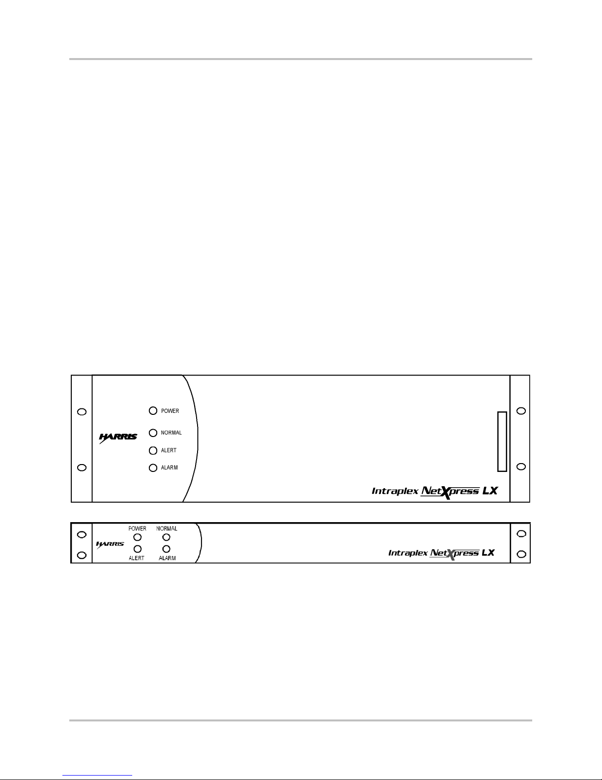
● NetXpress LX-300 – 19-inch wide, 5 ¼-inch high 3RU (Figure 1-1)
● NetXpress LX-100 – 19-inch wide, 1 ¾-inch high 1RU (Figure 1-2)
Figure 1-1. NetXpress L X-300 F ront Panel with Cover
Figure 1-2. NetXpress L X-100 F ront Panel with Cover
Each shelf is equipped with a CM-30 module, a MA-230 module adapter, and slots for plug-in channel
modules and module adapters.
The NetXpress LX-100 multip lexer has a single built-in AC pow er s upply. The LX-300 multiplexer has a
single plug -in AC or DC power supply and optional secondary plug-in AC or DC supplies.
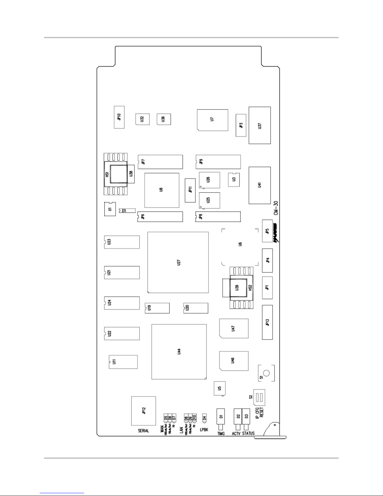
1.4.2 CM-30 IP Interface Module
The CM-30 module (Figure 1-3) is the comma nd center for the NetXpress LX IP multiplex ing system.
1-2 Harris Corporation
Intraplex Produc ts
Page 9
1 – Introduction NetXpress LX & CM-30 Installation & O p er ation Manual
Version 1, September 2010
Harris Corporation 1-3
Intraplex Products
Figure 1-3. CM-30 IP In terface Module
Page 10

NetXpress LX & CM-30 Installation & Operati on Manual 1 – Introduction
Version 1, September 2010
This module acts as an IP network interface, a packet engine, and a system manager. When coupled
with the MA-230 module ada pter (Section 1.4.3), the CM-30 module provides sh elf m a nagement
control, WAN an d LAN traffic control throu g h 10/100Base-T ports , and timing contr ol for external
stream traffic and system synchronization.
You can use a CM-30 module in place of, bu t not at the same time as, a T1 or E1 common module
(CM-3, CM-5, CM-5RB, CM-6, CM-7, or CM-7RB) in an existing Intra p lex T1 or E1 multiplexer. Y ou can
then revert back to T1 or E1 at a la ter da te by simply removing the C M-30 module and reinserting the
original common m od ule.
1.4.3 MA-230 Module Adapter
The MA-230 module adapter provides connectivity for the CM-30 module. The MA-230 module adapter
connects to the CM-30 module in the rear of the shelf and features these communication ports:
● Two 10/100Base-T ports (WA N an d LAN)
● Timing in/out for external stream an d s ystem synchroniza tion
● Contact I/O f or external control
1.4.4 Other Modules and Module Adapters
The NetXpress LX system offers five channel card slots (1RU shelf) or 17 channel card slots (3RU
shelf) for Intraplex audio, voice, and data modules.
Intraplex module a d a pte r s are installed in th e rear of the shelf a nd work in conjunction w ith the
channel access cards installed in the front.
1.4.5 Indicator Lights
Four system status indica tor lig hts located on the NetXpress LX power su pply a r e visible when the
front shelf cover is on (Figures 1-1 and 1-2).
● POWER – This green light is on when the multiplexer is pow er ed.
● NORMAL – This green light is on when no major nor minor alarm is present.
● ALERT – This yellow light is on when a minor alarm condition exists.
● ALARM – This red light is on when a major alarm condition exists.
Section 5 defines major and minor alarm c onditions.
The CM-30 module has indicator lights as well, which are visible when the front shelf cover is off.
Section 3.2.2 gives more information about CM-30 indicator ligh ts.
1.5 Web Browser User Interface
You can control functionality of your NetXpress LX unit and access network statistics and system
status through the NetXpress LX Home page. You can choose to ru n simultaneous software windows;
each connected to a differen t N etX pr es s LX system in the network. The Web browser interface, in
conjunction w ith an SNMP network manager, lets you control and monitor your system from one
operation center. You can access the Home page from the netw or k management system to research a
particular problem or obtain a grap hical view of system configuration or s ta tus. Section 4 –
“Configuration & Operation” giv es more information on this interface software.
1-4 Harris Corporation
Intraplex Produc ts
Page 11

No header here
Section 2 – Functional Design
This section describes the intent of IP multiplexing and day-to-day operations of the NetXpress LX
system and the CM-30 IP interface module. The section also describes how to use the IP multiplexer
and interface module to configure real-time payl oad transport of audio and data over exis ting IP
networks.
Packet-based media transport with the N etX pr es s LX system or the CM -30 m odule provides
● Transport of aud io, voice, data, and video.
● Flexibility when integrating to bus iness applications, systems, and networks.
● Network monitoring.
● Error mitigation .
● Transition and mig r a tion from legacy sys te m s with reuse of modules and components.
2.1 Network Concepts and Considerations
When looking at th e N etXpress LX system (or the CM-30 module) and packet-switched services as a
whole, consider these net work-related concepts:
● MTU throughout the network
● DHCP use
● Routing table con s truction
● WAN port auto-negotiation
● ICMP support
● Redundant WA N lin k configuration
● IGMP multicast
2.1.1 MTU throughout the Network
Prior to configuring a stream, you need to know end-to-end MTU (Maximum Transmission Unit)
between stream endpoints, which you can measure using an external server or router and running the
“Path MTU” tool. The stream payload must be smaller than the path MTU, otherwise fragmentation
occurs, the stream does not come up, and the NetXpress LX system does not support re-assembly.
2.1.2 DHCP Use
Dynamic Host C onfiguration Protocol ( D HCP) is a network pr otoc ol that enables a D HCP server to
automatically assign an IP address to an individual computer’s IP network interface. DHCP dynamically
assigns a number from a defined r a nge of numbers configured for a given network.
The NetXpress LX system supports dynamic address assignment for its LAN interface using DHCP. On
the WAN interfa c e , only static IP addres s assignment is supp or ted . You can elect to enab le the DHCP
option for the management interfac e from the Networking Ethernet Interfaces Web page (Section
4.3.4 – Configure the Ne twork). If DHCP is enabled and the system fails to successfully retrieve an IP
address, it defaults to the factory default address – 192.168.1.1.
2.1.3 Routing Tab le Construc tion
The behavior of the NetXpress LX system within the customer’s network is that of a n IP host. As such,
the NetXpress LX routing table is used sole ly to route internally generated packe ts . For streams that
are unicast, the determination of the next-hop gateway to reac h the remote NetXpress LX shelf is
done by examinin g the system routing tab le.
Harris Corporation 2-1
Intraplex Products
Page 12

NetXpress LX & CM-30 Installation & O p er ation Manual 2 – Functional Design
Version 1, September 2010
Routes in the rou ting table fall into two ba sic categories: a utomatic routes and user-defined routes.
The NetXpress LX system adds automatic routes based on the interface IP addresses. These routes
are called “directly connec ted” routes and are present to identify local subnets. If the destination for
all NetXpress LX traffic (stream and management) is to a host on its local subnet, no user routes are
needed. In most cases, how ever, you need to add routes to remote n etw orks or hosts so that the
NetXpress LX system can successfully send traffic to it. In the simples t c ase, if there is only one
gateway on its WAN subnet, a default route (such as 0.0.0.0/0.0.0.0 next-hop “gatew ayIP”) pointin g
to that gateway should be added. You can manage the NetXpress LX routing table from the NetXpress
LX Home page (Section 4.3.4.2 – Forwarding Table) or via direct SNM P access of the proprie tary route
management MIB (Management Information Base).
2.1.4 WAN Port Auto-negotiation
The auto-negotiation mechanism accommodates multi-speed Ethernet network devices. Autonegotiation occurs when a physical connection is made between a NetXpress LX Ethernet port and an
Ethernet port on a network switch or r outer. During this proc ess, the two Ethernet devices use a
protocol to determine at what speed (10 Mbps or 100 Mbps) they commu nicate and whether the
exchange of data occurs in a half-duplex (only one end transmits a t a tim e ) or full-duplex manner.
With the NetXpress LX system, you can enable or disable auto-negotiation for the WAN ports beca use
it is crucial that the link characteristics are set correctly to facilitate the tra nsmission of stream d a ta .
Auto-negotiation should be e nabled when the network port to which the NetXpress LX system is being
connected is capab le of negotiating t o a mode of 100 Mbps or 10 Mbps and full -duplex operation.
When auto-negotiation is disabled, each Ethernet port is set to o per a te at 100 Mbps speed in fullduplex mode, the op timum setting. I f the anticipated str eam data rate is low en ough, the WAN port
can operate effectively at 10 Mbps. Operating the W A N por t in half-duplex mode should be avoided.
Both sides of the lin k need to be set for auto-negotiation. I f not, the NetXpress LX system configures
itself for 10 Mbps, half duplex , and streams experience dropp ed pa c kets due to collision on the
Ethernet link.
The LAN port is always set to auto-ne gotiate. The mana ge m ent port can satisfy its f unction even when
operating at 10 Mbps in half -duplex mode.
Note: Do not operate auto-negotiation on only one side of the NetXpress LX link . To work properly,
both sides (NetXpress LX system and connecting dev ice) m ust be enabled for auto-
negotiation. The NetXpress LX system does not revert to 100 Mbps full-duplex if it is
configured to auto-negotiate and the other device is manually configu r ed for 100 Mbps fullduplex.
2.1.5 ICMP Support
The ICMP (Intern e t Control Message Pr otocol) delivers e r r or and control messages from hosts to
message requestors. An ICMP test may determine whether a des tin a tion is reachable. The ICMP
messages typically report errors in the processing of datagrams. A dd itionally, ICMP provides flow
control and first-hop gateway r edirection. On the NetX p r ess LX WAN port, the r e is an option to block
ICMP error messages, but the “ping” messages are always allowed.
2.1.6 IGMP Multicast
The NetXpress LX system (or the CM-30 modu le in an original Intr aplex system) interoperates with
multicast routers u s ing the Intern et Group Management Pr otocol (IGMP). The IGMP Mu lticast mode
involves transmission to specific hosts through IGMP routers. This scheme allows you to route specific
packets onto specific segments, thereby segregating unwanted traffic from na r row segm ents.
The NetXpress LX system supports IGMP v2 messages. When a “receive” multicast stream is
configured, it sends out IGMP membership reports. Similarly, when the multicast streams are deleted,
the NetXpress LX system sends out an IGMP Leave message and also responds to the membership
2-2 Harris Corporation
Intraplex Produc ts
Page 13

2 –Functional Design NetXpress LX & CM-30 Installation & O p er ation Man ual
Version 1, September 2010
queries from the router. It supports the proprietary IGMP statistics MIB to account for all incoming and
outgoing messages.
2.2 Streams
Within the NetXpress LX multiplexer or an original Intrap lex multiplexer, th e CM-30 IP interface
module uses packet streaming to transport audio signals.
2.2.1 Stream Types
2.2.1.1 Unidirectional versus Bidirectional
Packet streams c an be unidirectional or bidirectional. In other words, streams can travel in one
direction (transmitted or received) or two directions ( tr ansmitted and rece ived). The CM-30 module
supports both u nidirectional and bid ir ect ion al pack et str eam ing.
Most circuit types (su ch as voice and two-way data circuits) are bidirectional, or full-duplex. Fullduplex circuits re quire identical f ull-duplex (transmit or receive) channel modules at both ends of the
channel they occupy within a system. Other circ uit types (such as program audio channels) are
unidirectional (simplex ) . They always have a transmitter modu le a t on e end and a receiver module at
the other. Most bid ir e c tional (full-du plex) channel modules can also be set up to operate in a
unidirectional (simplex) mode.
2.2.1.2 Unicast versus Multicast
Packet streams can also be classified as unicast or multicast. Unicast describes transmitting a piece of
information (a pa c ket stream in this c a se) from one point to an other point. Unicast transfer mode is
still the predomin ant form of transmission on LANs and within the Internet. Standard unicast
applications include HTTP, SMTP, FTP, and Telnet.
Multicast descri b es communication w here a piece of inform a tion is sent from one or m or e points to a
set of other points (a multic a s t gr ou p a ddr es s ) . There may be one or more senders a nd the
information is sent to a set of receivers (there may be no receiver or any number of receivers). With
multicasting, the same packet is delive red simultane ously to a group of c lients. Multicast applic ations
must use the UDP (User Datagram Protoc ol) tr ansport protoco l, since TCP (Trans m ission Control
Protocol) only supports the unic a s t mode.
Most circuits provided by Intraplex m ultiplexer syste m s are unicast, including those provided with the
NetXpress LX system. However, several types of c hannel modules can be configured for poin t -tomultipoint opera tion (multicast) . For example, you can set up a single program audio tra nsmitter
module and several program audio receiver modules in a point-to-multipoint or “ br oadcast” circuit
configuration, allowing multiple loc ations to receive the same program audio signal.
If your network does not support multicasting, you can configure the NetXpress LX system to m ultiunicast up to four destin a tions. The programm ing source must be in contiguous time slots on TDM Bus
A. The receivers can be on the in ternal TDM bus. Section 4.3.3.4 – TDM Bus Mapping Configur ation
gives additional mu lti-unicast infor mation.
2.2.1.3 Voice Streams versus Data Streams
Streams which are intended to carry in formation for voice gr a d e audio modules of ten require
additional signaling information to s upport pulse dialing, off-hook con d ition call progress or ringing
states. Special signaling support is required to transport this added information. V oic e a udio streams
carrying telephone calls are also prone to audio echo back from the receiver. You can use echo
canceling circuits to eliminate this p r oblem. Streams us e d for transporting linear or compressed
wideband audio modu les or other forms of raw information p r esent their data d ir ectly into each
channel and do not require signaling s upport.
Harris Corporation 2-3
Intraplex Products
Page 14

NetXpress LX & CM-30 Installation & O p er ation Manual 2 – Functional Design
Version 1, September 2010
2.2.2 Stream Addressing
The stream addressing process involves designating a de s tination IP address for both unicast and
multicast IP streams (Section 4.3.5– Configure Streams). During the process of adding streams,
individual streams are designated as either unicast or m ulticast in the Transmission Type field (Section
4.3.5.1 – Stream Creation).
When you create a stream, a UDP port number must be specified for both the lo c a l a nd remote
NetXpress LX devices. The RTP protocol convers a tion between the two devices tak es pla c e through the
specified UDP ports.
The range for UDP port numbers must be greater than or equal to 5000 0 a nd a multiple of 5, ending
in either a 0 or a 5. For unicast and multicast receive streams, the combination of peer’s IP address
and source and destination UDP ports must be unique. For multicast transmit streams, each stream
must have unique ports.
Many networks use a device known as a “ firewall” at the entry point to the network to prov ide security
against hackers and other undesira b le applications. Usually, network d evices in the private network
behind the firewall can freely transmit out using any UDP port number. However, devices ar e blocked
from receiving packets using a UDP por t number until a packe t is tr ansmitted out th e firewall using the
same UDP port. When setting up the network for a NetXpress LX installation, you may need to
configure the firewall to allow commun ic a tion on the UDP port nu m b er s used for stream tra ffic before
attempting to brin g up a stream.
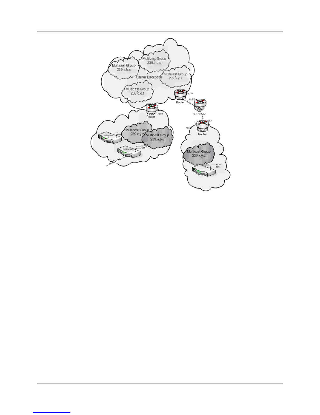
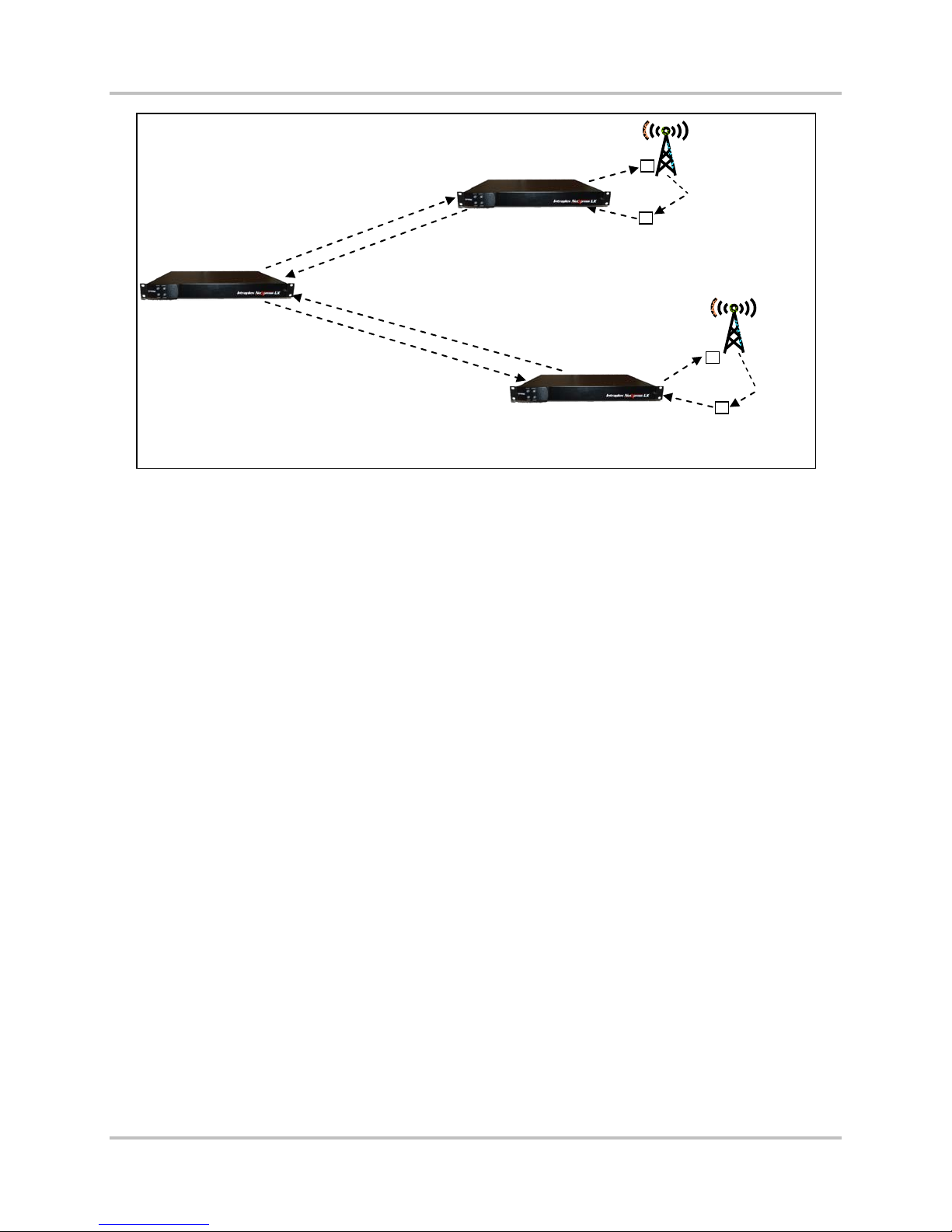
2.2.3 Multicast Group Addressing
The CM-30 IP interface module, within the NetXpress LX system or an original Intraplex sy s tem,
supports multicast use for stream transmission and supports creating up to 32 transmit, receive, or a
combination of tr a nsmit and receive str e a m s. This system does n ot m ake any restriction s on the type
of multicast address used for a stream destination. Therefore, you determine how you want the
multicast address space to be administered. Figure 2-1 represents a scenario where multicast
addresses are “administratively scoped.” However, some customers may also require GLOP
assignment by the carrier WAN, using address ranges 233.x.x.x, and the NetXpress LX system can
accommodate that addressing scheme as well. Section 4.3.5.1 – Stream Creation gives additional
information regarding multicast addresses.
2-4 Harris Corporation
Intraplex Produc ts
Page 15
2 –Functional Design NetXpress LX & CM-30 Installation & O p er ation Man ual
Version 1, September 2010
Figure 2-1. Carrier Multicast Backbone Example
2.2.4 Telephony
The CM-30 module and NetXpress LX system allow you to cr e a te streams whose endpoints are
Intraplex voice channel modules that s upport telephone s ignaling (for examp le, the VF-15E, VF-16AE,
and VF-25 modules). The voice circuits generate signaling bits which the NetXpress LX system
transports out-of-ba nd and reinserts onto the NetXpress LX intern a l T DM bus at the receive end. No
more than 20 telephony streams are a llowed in-service at one time.
Telephony streams can be easily iden tified in the stream table by the tel ephone icon after the stream
name. The color of the icon, (red, yellow, or green) indicates the current status of the out-of-band
signaling transfer. The NetXpress LX Performance menu provides statistics on sig naling packet
transmission, and these statistics are cleared when the other stream statistics are cleared.
The TDM bus in T1 systems inherently supports signaling. In E1 systems, the signaling bits are carried
on the internal TD M bus using Channel A ssociated Signalin g ( CAS). Telephony streams need to
originate and term inate on busses where the CAS mode is enabled. You can s elec t th e s pec if ic T D M
busses for the telephony strea m s on the TDM Bus Edit screen (System Config | TDM Bus | TDM
Bus Edit). When the CAS mode is enabled, the NetXpress LX system uses Time slot 16 to car r y the
signaling bits for a ll the other channels on that bus; this time slot is not available to carry normal
traffic.
2.2.5 Echo Cancellation
The NetXpress LX system can provide echo c a ncellation for voic e circuits using up to 2 optional echo
canceller cards that plug onto the CM-30 modu le. Each board can provide echo cancellation for up to
30 channels per echo canceller card on the TDM bus.
Echo cancellation can only be enabled f or full-duplex str ea ms with identical bus/cha nnel configuration
in the transmit (Tx) and receive (Rx) direction, and both en dp oints of the stream need to have an
echo canceller card installed. Echo cancellers are needed in 2-wire modules (for example, the VF-15E
Harris Corporation 2-5
Intraplex Products
Page 16

NetXpress LX & CM-30 Installation & O p er ation Manual 2 – Functional Design
Version 1, September 2010
or 16AE module) but not in 4-wire modules (for example, the VF-25E module). When using echo
cancellation, you should not configure streams to enca ps ulate more than 60 fr a mes per packet.
2.2.6 Packetization and Overhead
Packetization is a process in which frames of data from the TDM bus are collected into IP packets f or
transmission th r ough the IP network . A frame on a NetXpress LX T D M bus is divided into 32 par titions
or time slots, each containing a byte of data. Because of the serial nature of the TDM bus, an entire
TDM bus frame encompasses 125 µs in time. The stream packetization interval def ines the number of
TDM frames collected by th e NetXpress LX sy stem into a single packet for transmission. The higher
the packetization interval, the greater the accumula tion delay introduce d to the program because each
frame must be accumulated befor e th e pa c ket can be created. Note that the tot a l progr a m delay is a
combination of pa cketization delay a nd network delay.
Each packet in a NetXpress LX stream contains 44 bytes of non-program data (overhead)
corresponding to the header infor m a tion required for th e IP, UDP, and RTP protocol la yers. The ratio of
non-program data to program data for a packet can be considered the overhead requ ir ed to get the
packet through the network. The higher the overhead, the more the network b a ndwidth available t o
an application used to transmit non-program data. Program delay can be m in im iz ed by using a small
packetization interval at th e expense of an increase in overh ea d. Conversely, increasing the
packetization interval decreases the ov er head but increases the program de la y (Table 2-1).
Another overhead determination factor is the number of time slots from each TDM frame that get
placed in the packet. As this number increases, the stream overhea d dec rea s es because the ratio of
overhead data to program da ta dec r ea s es . However, the number of time s lots consumed from each
frame does not affect the progra m delay. Therefore, it is desirable t o c ombine time slots from a TDM
bus headed for th e same destination into a single stream to reduce overhead and to make the best
use of available network bandwidth.
2.2.7 Packet Jitter Compensation
In an IP network, the time required for a pa cket to travel through the network from s e nder to receiver
is not guaranteed to be maintained. As a r es ult, the receiver can see the interva l betw een the arrival
of packets vary throu ghout the rec eption of the packet stream. For a giv en packet, the difference
between the packet’s delay a nd the average of the delay values for all packets in the stream is known
as jitter. The jitter can be pos itive or negative depending on whether the packet delay is less than or
greater than the average delay .
For many network services, packet jitter is not an issue, and no techniqu e is needed to compensate.
However, the continuous playout nature of audio and video require that there must be s ome means of
guaranteeing that the receiver always has the next pack et of da ta w hen the previous packet is
consumed. Th e r eceiver must also hold onto pa ckets that arriv e early so that they a re available for
playout at the prop er time.
The NetXpress LX system compensates for s tr eam packet jitter through the use of a jitter buffer. The
system maintain s a jitter buffer for ea ch stream on the receiv e s ide . The buffer is siz ed s o that the
buffering delay is greater t han the maximum packet delay expected through the network. In the
NetXpress LX system, you specify the jitter buffer size in number of packets rangin g from 8 to 128
(Section 4.3.5.1 – Stream Cr ea tion). The packetization interval of the stream controls the amount of
packet delay for which the jitter buffer can compensate. I ncreasing the number of TDM fra m es
contained in a pac ket increases the size of the jitter buf fer as measured in time.
2.2.8 Packet/Stream Information Calculation
Table 2-1 gives an example of user and computed parameters for a NetXpress LX stream. The user
parameters represent us er -defined stream parameters. The computed parameters ar e for packet
information and network bandwidth based upon the user parameters. This table also gives formulas
for how to derive com puted parameters for a stream.
2-6 Harris Corporation
Intraplex Produc ts
Page 17

2 –Functional Design NetXpress LX & CM-30 Installation & O p er ation Man ual
Version 1, September 2010
Table 2-1. NetXpress LX Stream User and Computed Parameter s
User Parameter Value Description
Number of TDM
Channels
TDM Frames per
Payload
Jitter Buffer Size
(8 – 128 packets)
Computed Parameter Value Description Formula
TDM Channel Data Rate 64 kB/S Calculated TDM channel data rate in kB/S Number of TDM Channels x 64
Packet Payload Size 160 bytes Calculated payload size in each packet in
Packet Interval 20 mS Calculated packet interval (time between
Packet Rate 50
Jitter Buffer Delay 640 mS Calculated jitter buffer delay in mS
Ethernet Frame Size 242 bytes Calcula te d Ethe rnet frame size in bytes =
Ethernet Stream Data
Rate
IP Packet Size 204 bytes Calculated IP packet size in bytes =
Stream Data Rate 81.6 kB/S Calculated IP s trea m data rate in kB/S * IP Packet Size x Packet Rate x
1 Number of TDM channels to transport in a stream
160 Number of TDM frames per payload (packet)
64 Configured jitter buffer size in packets
bytes
packets) in mS
packets/S
96.8 kB/S Calculated Ethe r ne t str e am data rate in
Calculated packet rate for a stream in
packets/S
Note: This delay assumes a receive
queue of half the jitter buffer size
Packet Payload Size + Ethernet overhead
(38 bytes – no VLAN) + IP overhead (20
bytes IP + 8 bytes UDP + 16 bytes RTP)
kB/S *
Packet Payload Size + IP overhead (20
bytes IP + 8 bytes UDP + 16 bytes RTP)
Number of TDM Channels x
TDM Frames per Payload
Number of TDM Frames per
Payload ÷ 8
(1 ÷ Packet Interval) x 1000
Jitter Buffer Size x Packet
Interval ÷ 2
Packet Payload Size + 38 + 44
Ethernet Frame Size x Packet
Rate x 8 ÷ 1000
Packet Payload Size + 44
8 ÷ 1000
* In most instances, Ethernet overhead is stripped before the pac k et is tra nsported over a WAN link.
However, in cer tain instances (su c h a s Metro Ethernet networ ks that transport the entire frame);
the Ethernet overhead is left on the packet.
2.2.9 Stream Statistics
NetXpress LX stream statistics are receiver-based. The time interval for collecting stream statistics is
user-selectable (from 5-10 seconds for each stream). It is a good practice to review your stream
statistics on a regularly scheduled basis (Section 4.3.6.1 – Stream Statistics). Y ou may be able to
modify your NetXpress LX system for optimum throughput, bandwidth efficiency, and reduced errors.
As an example, you may wish to alter the siz e of the jitter buffe r if you are experiencing too many
lost, underrun, early, or late packets. Specifically , if you are experienc ing too many late packets, you
might need to increase the jitter buffer size.
2.3 System Security
System security is controlled throu gh
● Logon and passwor d c ontrol.
● Interface protocol mana gement enabling and disabling.
● An IP access list.
Harris Corporation 2-7
Intraplex Products
Page 18
NetXpress LX & CM-30 Installation & O p er ation Manual 2 – Functional Design
Version 1, September 2010
● Establishment and and control of SNMP Com m unities.
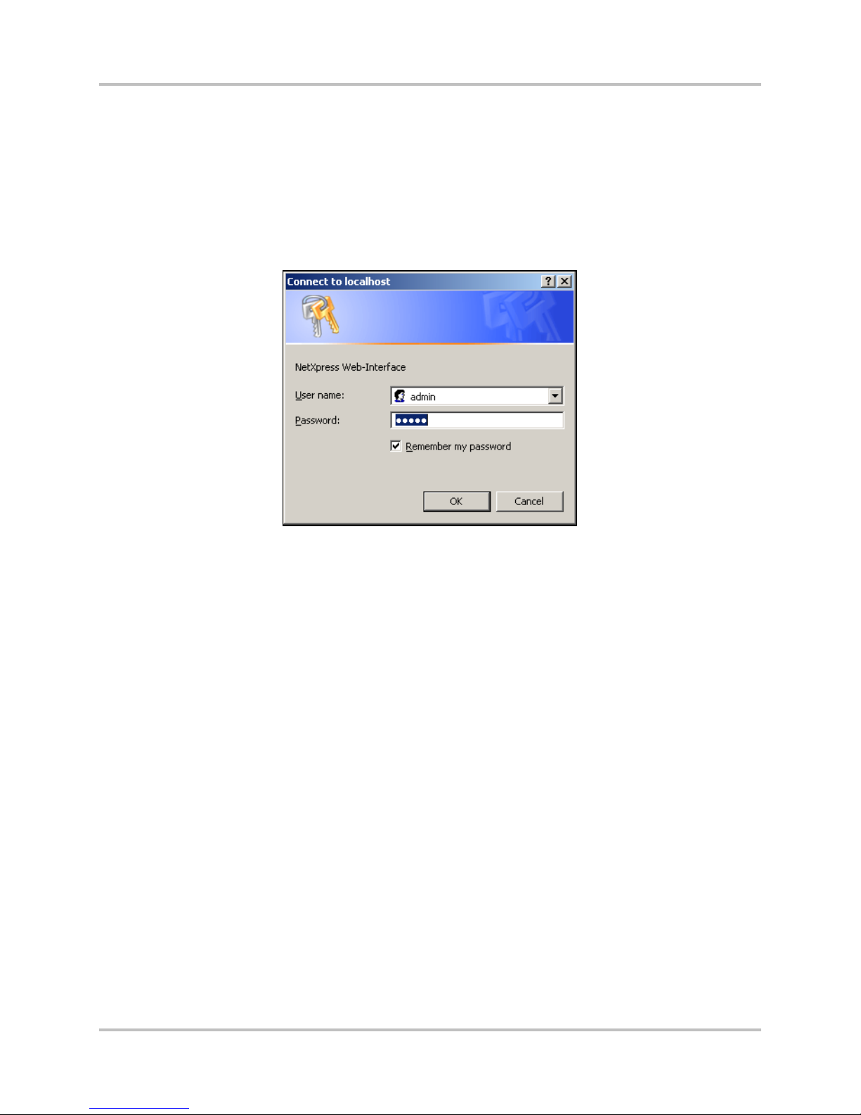
2.3.1 NetXpress LX Login
When you launch the Web server interf a c e a p plic ation, the system immediately displays the logon
screen (Figure 2-2). You must type the proper user name a nd password to gain access to the
NetXpress LX Web interface. Before it is c onfigured, the NetXpress LX system has a default
administrator user name of “admin” and default password of “admin” for the Web interface. Once you
initially log on, you can change the Web interface administrator password, as well as administrator
and guest accounts for Web FTP access (Section 4.3.7.1 – Accounts).
Figure 2-2. NetXpress LX Web Interface Logi n
2.3.2 Management Protocols on an Interface
The NetXpress LX system comes with two Ethernet interfaces:
● WAN
● LAN
The LAN interface allows you to run all managem ent traffic on a separate network if desired.
By default, each interface accepts HTTP and SNMP protocols and allows FTP and Telnet sessions to be
established. You can use the interface screens in Section 4.3.4 – Configure the Network to enable or
disable differen t p r otocols for each interface. Contr olling protocols by interf ace enables you to
● Tighten security
● Block unwanted tr a ffic
● Ensure network privacy
2.3.3 IP Access List Use
You can add secur ity to your NetXpress LX installation b y limiting access based on specific IP
addresses (Section 4.3.7.2 – IP Access List). You can also use th e s a me networking configuration
screen to specify which interface can be used to gain access to the system.
2.3.4 SNMP Communities
An SNMP community is a group of hosts that you can man age as a distinct group with SNMP. You
must use a community name for all SNMP c onversations to take p la ce. You can use the same name for
2-8 Harris Corporation
Intraplex Produc ts
Page 19

2 –Functional Design NetXpress LX & CM-30 Installation & O p er ation Man ual
Version 1, September 2010
a read-only community a nd a r e a d -write community, or you can specify two different nam e s to r e s tr ict
write-access to the system.
2.4 NetXpress LX QoS
Quality of Service (QoS) / Class of Service (COS) mechanisms can reduce flow complexity by mapping
multiple flows in to a few service levels. N etwork resources are then allocated ba s ed on these service
levels and flows can be aggregat ed a nd forwarded according to the ser vice class of the packet.
2.4.1 COS Levels for Stream Data
The class of service (COS) level for a stream is established when the strea m is created. The NetXpress
LX system offers four COS levels (high, normal, medium, low) for stream data (Section 4.3.5.1 –
Stream Creation). The classes are based on service priority; the higher the priority, the more
immediate the handling of the stream. For example, program audio is critical in many operations, so
when a stream is configured for program a udio, you designate a high class of service le vel for that
packet stream. C onversely, a voic e c ircuit might be consider ed less critical to operations, so y ou might
specify a lower COS level.
2.4.2 TOS Byte Marking for Outbound Stream Packets
In an IP network, all IP packets contain a field in the IP header called the Type of Service (TOS) by te.
The value of the TOS byte tells the network what quality of service needs to be applied to the packet.
You can define what the value of the TOS b yte field should be for ea c h of the four classes of service
supported by the NetXpress LX s ystem for stream packets. The system pla c es the appropriate TOS
byte value corres ponding to the COS pr ovisioned for a stream in every outbound data p a c ket for that
stream (Section 4.3.4.3 – Class of Service). Since TOS byte value can be set to any value per class of
service, the NetXpress LX system can operate in networks using Differential Services (Diff Serv) QoS
and networks em p loying the standard T O S interpretation for QoS.
2.4.3 User-Defined TOS Byte Setting for Outbound SNMP and HTTP
Packets
In addition to suppor ting the TOS marking for stream data, the NetXpress LX system allows you to
configure the TOS byte value placed in all outbound SNMP and HTTP packets. Therefore, SNMP
management traffic and Web interfac e tr a ffic to be handled in the network with a d ifferent class of
service than other packets.
2.5 NetXpress LX Internal TDM Busses
The NetXpress LX IP multiplexer uses two TDM busses to support data transfer for audio channels.
These busses (TDM Bus 1A and TDM Bus 1B) can be configured to operate in T1 or E1 mode.
Note: Both A side and B side busses operate in th e s a m e mode; you cannot have a T1 bus and an E1
bus.
When set for T1 mode, the TDM bu sses support robbed-bit signaling. When set for E1 mode, the TD M
busses in the NetXpress LX system support CAS (channel associated signaling) and CCS (Common
Channel Signaling). With CAS sign aling, time slot 16 is always reserved for telephone signaling. The
data rate is fixed at 1.544 MHz (T1 mode) or 2.048MHz (E1 mode). In E1 mode, you can enable or
disable signaling.
2.5.1 Compatibility with Intraplex TDM Channel Modules
Nearly all Intra p lex TDM channel modules are compatible with the NetXpress LX multiplexer. Table 2-2
shows currently supported modules.
Harris Corporation 2-9
Intraplex Products
Page 20

NetXpress LX & CM-30 Installation & O p er ation Manual 2 – Functional Design
Version 1, September 2010
Table 2-2. NetXpress LX-supported TDM Chann el Modules
Module
PT-150A 4.7
PT-150B 4.0 PR-D150 6.6 DA-191B 1.2
PT-150C 4.0 PT-D350 3.0 DA-91A 1.0
PR-150A 6.6 PR-D350 3.4 DA-91i 1.0
PR-150B 6.0 PT-D355 3.0 DS-64NC 2.5
PR-150C 6.0 PR-D355 3.4 D-100 3.0
PT-153 5.5
PR-153 5.5 VF-16AE 2.3 DS-961D 1.2
PTR-155 5.0 VF-16E 2.3 DS-961DE 1.2
PT-250 3.0 VF-25E 2.0 DS-961DF 1.2
PR-250 3.4 VF-27E* 2.0 DS-961DG 1.2
PTR-255 7.7 VF-28E 2.0 DS-965 1.2
PT-350 3.0 VF-29E 2.0 DS-966 2.5
PT-350B 3.0
PT-350C 3.0 VF-16 2.3
PR-350 3.4 VF-16A 2.3
Nominal
Power
(watts)
High Fidelity
Nominal
Module
PT-D150 4.7
Input / Output
Program Audio
Modules–AES\EBU
VF-15E 2.3 DS-562i 2.0
Voice Modules for E1
VF-15 2.3 OCU-DP 2.0
Power
(watts)
Module
DA-191A 1.2
Data Modules
Nominal
Power
(watts)
PR-350B 3.4 VF-25 2.0
PR-350C 3.4 VF-27* 2.0
PT-353 3.0 VF-28 2.0
PR-353 3.4 VF-29 2.0
PT-355 3.0
High Fidelity Program Audio Modules – Analo g Inp u t/ Output
PT-355B
PT-355C
PR-355 3.4
PR-355B 3.4
PR-355C 3.4
3.0
3.0
Secure
Voice Modules for T1
VF-40 2.0
DV-600 5.0
Voice
Digital
Modules
DV-600A 5.0
* Neither the VF-27 nor VF-27E module supports or oper a tes with E & M signaling when used in a
NetXpress LX system.
You must configure each channel module to use either TDM Bus 1A or TDM Bus 1B. Also, if the TDM
busses are set for E1 operation, you must provision the bus itself to use CAS signaling and then
provision each module on the bus to infor m it that CAS signalin g is in use. Each TDM bus has its own
frame loss signal to tell the modules to mute if there is a problem with th e a rr iving data intended for
that particular bus.
2-10 Harris Corporation
Intraplex Produc ts
Page 21
2 –Functional Design NetXpress LX & CM-30 Installation & O p er ation Man ual
Version 1, September 2010
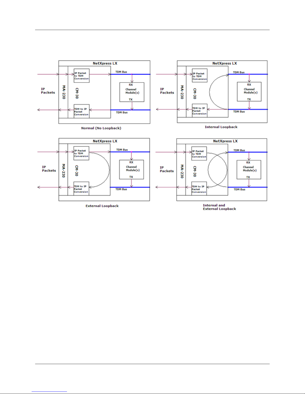
2.5.2 TDM Channel Loopbacks
Figure 2-3 shows the normal/default of no loopback and the three Time Divis ion Multiplexing (TDM)
channel loopback scenarios for channel modules and TDM busses: internal, external, and both.
Figure 2-3. NetXpress LX TDM Loopback Scenarios
When you apply the internal loopback to a time slot or a group of time slots on the TDM bus, the
channel module data is copied back to the receive channel on that same TDM bus, as well as being
transmitted to its IP targets. Wh en you apply the external loopback to a time slot or a group of tim e
slots on the TDM bus, the received data is d eliv ered to the channel modu le on t h at same TDM bus as
well as being trans m itted back out to its originating sour c e. You can apply both internal and extern al
loopbacks simultaneously. This e xample shows loopba c ks for an entire bus. However, you can also
loopback individual time slots within a bus.
2.5.3 TDM Bus Mapping
The NetXpress LX or CM-30 TDM bus is connected by default to a virtua l IP bus; this connection is bidirectional. The TDM bus mapping fea ture allows you to r econfigure your c onnections to suit your
needs. You can connect a time slot from TDM A, TDM B, or either of the echo cancellers to the
corresponding tim e s lot on any of the 4 IP ports . You can connect a time s lot from TDM A or TDM B to
the corresponding time slot on either of the echo cancellers.
The NetXpress LX system (or CM-30 module) has 2 bus map choices:
● The pre-configured default map has both TDM A and TDM B busses mapped from IP sources to
two (multi-unicast) IP destinations (connections) .
● You can select the User Defined Profile and create a customized bus map configuration. For
example, you can create a multi-unicast configuration, where one source is c onnected to more
than two destinations. Section 4.3.3.4 – TDM Bus M apping Configuration gives additional mult i-
unicast information.
Harris Corporation 2-11
Intraplex Products
Page 22

NetXpress LX & CM-30 Installation & O p er ation Manual 2 – Functional Design
Version 1, September 2010
2.6 System Time-of-Day
With the NetXpress LX system, ther e are two ways to set the s ystem time-of-day: 1) manually and 2)
via NTP (Networ k Timing Protocol) server . If you choose the latter method, you m ust use the Web
server interface to enable N TP in the NIM Configuration – General Setup screen and provide the IP
address of the SNTP server (Section 4.3.3.1 – General Setup). The NetXpress LX system maintains the
time and date in a battery-backed time-of-day clock on the CM-30 module.
2.7 System Timing
2.7.1 Types of System Timing
System timing is the process of s ynchronizing com munications and strea m traffic between two or
more NetXpress LX systems in a network. Time synchroniz ation is critical to the proper functioning of
the NetXpress LX network. It must be configured correctly.
The primary timing sour c e for all interconnected NetXpress LX systems should trace back to the same
long-term accurate oscillator.
Primary and secondary timing are conf igu r ed via the Web interface using the System Timing screen
(Section 4.3.3.5 – System Tim ing). You must specif y the timing source for both primary and
secondary timing. If the primary timing source is unava ila b le, the system uses secondary timing. The
NetXpress LX system provides four timing sources from which to choose:
● Internal
● External
● Stream
● SynchroCast
Timing can be sourced through the RS-422 Timing OUT port on the MIU-201 or MIU-202-2 to feed
additional multip lexers.
2.7.1.1 Internal Timing
Internal timing is derived from an ex tr emely accurate inter nal oscillator on the CM-30 module. In a
NetXpress LX network, only the m a ster NetXpress LX system can use inte r nal timing. Other NetXpress
LX shelves in the network must use external, stream, or SynchroCast timing derived from the n etw or k
master.
2.7.1.2 External Timing
External timing is usually a precision timing signal derived from a n external device th a t is traceable to
a stratum-1 timing source (for example, a public network WAN interface such as T1 or E1). External
timing is input through a connection to the Timing IN port on the MIU-201 or MIU-202-2. The external
timing input accepts an RS-422/RS-485 balanced clock signal. If external timing is selected as the
primary timing sou r ce on the master NetXpress LX system , external timing, stream, or SynchroCast
timing must be selected as the primary timing method for the subordinate NetX press LX systems.
2.7.1.3 Stream Timing
Stream timing is derived from the incom ing packet stream. A timing stream mus t have a packet rate
of 8 packets per second or greater (1000 frames/packet or less). Th is typ e of timing uses an algorithm
inherent in the TDMoIP chip. In a NetXpress LX network, only subordin a te NetXpress LX systems can
be set to stream timing mode. Th e NetXpress LX master system monitors stream traffic and adjusts
timing so that the su b or dinate shelves are s ynchronized with the master clock frequency. As a general
rule; the faster the packet rate, the be tter the stream timing. With stream tim ing, jitter buffer size can
be monitored and regulated to av oid bu ffer underflow/overflow a nd negate the effect of pack et delay
2-12 Harris Corporation
Intraplex Produc ts
Page 23

2 –Functional Design NetXpress LX & CM-30 Installation & O p er ation Man ual
Version 1, September 2010
variation. Whe n a subordinate system derives timing from the master, clock recovery algorithms are
employed to align c lock frequency an d c ontrol packet jitter/w ander. Also, in order to recover timin g
from a stream, the stream must be active and sending. Networking or router problems can result in
no timing recovery from a stream.
Note: When you configure several receive streams and use a stream as the timing source, you
should use the stream with the highest packet rate ( such as the lowest frames per payload
value) as the primary timing stream.
2.7.1.4 SynchroCast3™ Timing
The SynchroCast3 system uses a simulcast technique which transmits to an extended geographic area
using multiple, ov er lapping transmitters operating on the same frequency. Historically, broadcasts
from nearby transmitters on the same frequency have crea ted s erious reception problems where they
overlap. The SynchroCast system, or ig inally developed f or use in land mobile radio s ystems, makes
simulcasting possible in FM broadcast as well. The SynchroCast system can provide dramatically
increased station coverage while r ed ucing or eliminatin g unwanted artifacts at the listener’s receiver.
The SynchroCast3 system in the NetXpress LX multiplexer maintains the phase alignment of the
transmitted signals using Global Position S ystem (GPS) tech nology, providing
● GPS controlled car r ier frequency sy nchronization.
● GPS controlled precision audio pha s e a lignment.
● Dynamic adjus tm e nts to compensate for network routing c hanges.
The SynchroCast3 system sends timing reference signals along with the a udio content to the
transmitter sites. GPS receivers, placed at the Origination Point and transmitter sites, provide a timing
reference. At the Transmitter, timing signals coming from the Origination Point (along with the audio
content), are com p a r e d with the local timing reference and a p r ecise amount of delay is introduced to
correct the timing differenc e between transport paths. Once the signals are synchronized, the system
operates automatically to keep the preset delay constant. The Intraplex SynchroCast3 System
Installation an d Operation Manu al gives more inform a tion on the SynchroCast3 system.
The SynchroC ast3 system carefully controls the receive jitter buffers as sociated with the IP streams,
allowing multipl e loc a tions to deliver their stream data at pr ec isely the same instant. This control is
essential for radios using multiple transmitters so that interference p r oblems associated with them can
be minimized.
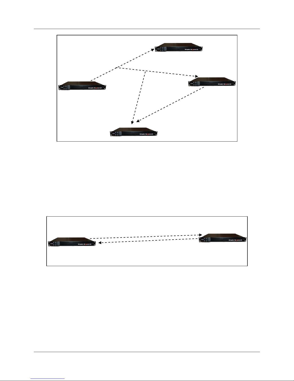
2.7.2 NetXpress LX Timing Scenarios
In a system that utilizes multiple NetXpress LX units de ployed on an IP network, it is important to
maintain consis tent synchronization of the internal NetXpress LX system clocks. This synchronization
ensures that any NetXpress LX system can receive streams generated by any other unit or a
combination of s tr e a m s from any other units (Figure 2-4).
Harris Corporation 2-13
Intraplex Products
Page 24
NetXpress LX & CM-30 Installation & O p er ation Manual 2 – Functional Design
B
INTERNAL
STREAM
Version 1, September 2010
NetXpress LX
Multicast Audio
Stream 1
NetXpress LX
C
NetXpress LX
A
Audio Stream 2
NetXpress LX units at sites A and
C must have synchronized
NetXpress LX
D
system clocks so that the
NetXpress LX unit at site D can
properly receive and process its
Figure 2-4. NetXpress LX Timing Synchronization
NetXpress LX units can derive sys te m tim ing in one of four ways:
1. An internal clock is av a ila b le, based on a local osci llator within the u nit (Internal Timing ).
2. An external clock can be appli e d to the unit (Exter nal Timing).
3. An incoming IP unicast or mu ltic ast stream (Stream Timing), thereby synchronizing its e lf to the
NetXpress LX unit that generated the stream.
4. SynchroCast, which incorporates a blend of Str eam and Extern al timing from GPS receivers.
Simple point-to-point sy s te m s commonly use a c om bination of intern a l and stream timing. Figure 2-5
shows the unit at s ite A set to internal timing, utilizing its local internal oscilla tor. The unit at Site B
derives timing from the audio stream tra nsmitted from Site A to Site B.
TIMING
NetXpress LX
A
TIMING
NetXpress LX
B
Figure 2-5. NetXpress LX Point-to-point Timi ng Synchronizati on
The configuration advantage in Figure 2-5 is simp licity of implementation. No external timing sources
are required. This configuration can be extended to multiple site systems by design a ting one site as
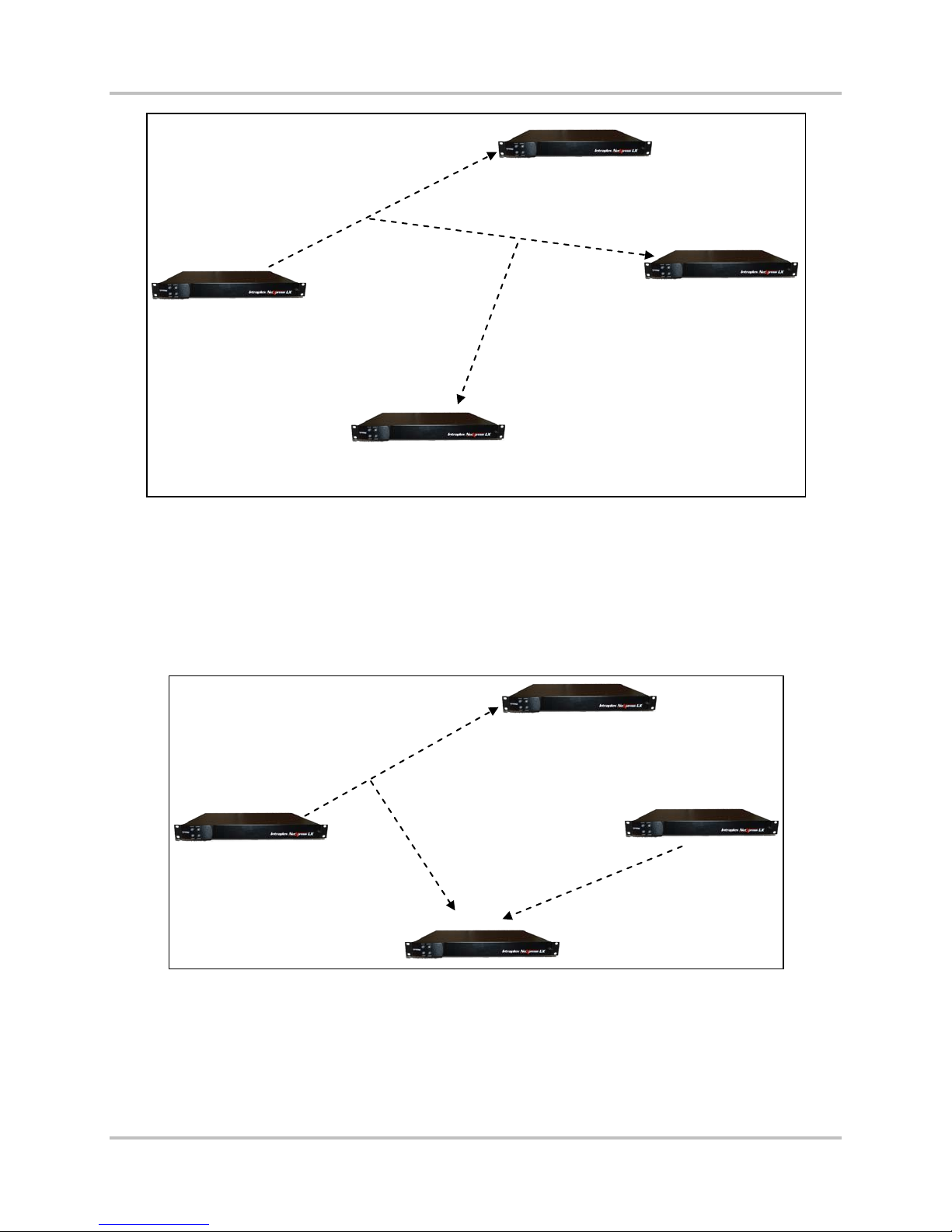
the master timing loc a tion and having th e r est of the sites derive timing from that site. Figure 2-6
shows such a system, with Site A using internal timing a nd the remaining sites using stream timin g to
achieve synch r onization to Site A.
2-14 Harris Corporation
Intraplex Produc ts
Page 25
2 –Functional Design NetXpress LX & CM-30 Installation & O p er ation Man ual
A
Stream Timing
NetXpress LX
B
NetXpress LX
Version 1, September 2010
Stream Timing
NetXpress LX
B
Internal Timing
NetXpress LX
NetXpress LX
Stream Timing
C
Sites B, C, and D use stream
timing to derive timing from
NetXpress LX
master Site A.
Figure 2-6. Stream Ti ming Synchroni z a t ion
This method of timin g distribution c a n be very simple and efficient in cases where pr ogr amming
streams are eman a ting from one master s ite to all the remaining sites. However, p r ogr amming may
be generated at mu ltiple sites within the network, and these program source sites may not all receive
program streams from the master site that can be used as timing sources (Figure 2-7). In this
example, Site A is the master timing sou rce, but Site C does not receive a stream f rom Site A and
therefore cannot synchronize its outgoing stream to the rest of the network. As a result, the two
streams received at Site D utilize different synchronization sources and cannot be properly received
and decoded.
Stream Timing
Internal Timing
NetXpress LX
A
Internal Timing
C
Site D cannot process both
NetXpress LX
D
incoming streams because they
have different timing sources.
Figure 2-7. Streams with Different Synchroniz a t ion Sources
There are two possib le solutions to this s ituation.
1. Receive a stream at site C from Site A solely for the pur pose of synchroniz a tion (Figure 2-4). The
cost of this solution is the additiona l b a ndwidth required in the network end-link to site C.
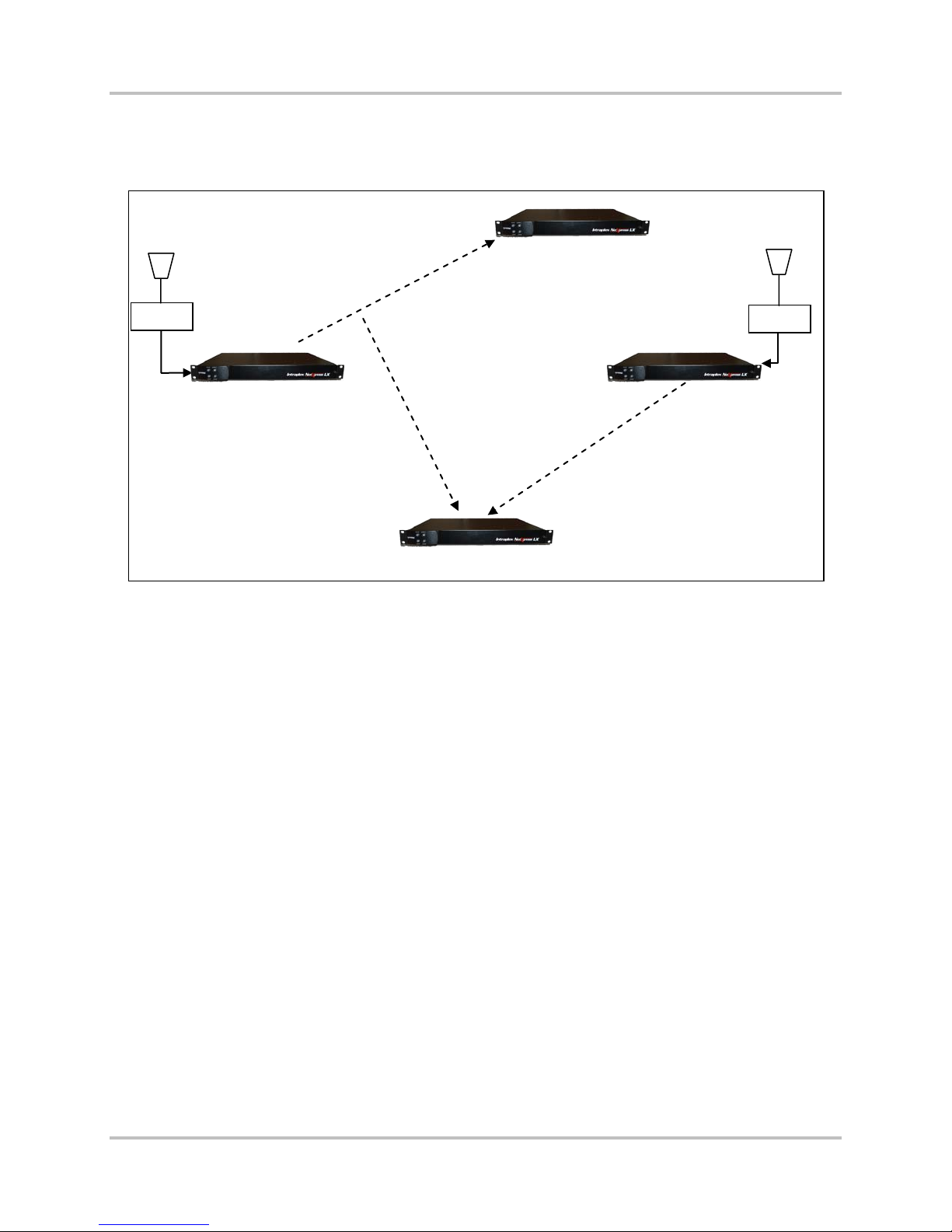
2. An alternative approach would be to utilize highly accurate exter nal timing sources at Sites A and
C to achieve netw or k synchronization. One example would be a Stratum 1 traceable t im ing signal
Harris Corporation 2-15
Intraplex Products
Page 26
NetXpress LX & CM-30 Installation & O p er ation Manual 2 – Functional Design
B
D
Version 1, September 2010
from a telecom networ k provider. An other source of accurate external timing signals is a GPS
receiver, usin g GPS timing at the stream timing sites (F ig ure 2-8). This solution guara ntees the
two streams received at site D have c ompatible timing, allowing Site D to time from either
incoming stream.
Stream Timing
NetXpress LX
GPS
External Timing
NetXpress LX
A
NetXpress LX
External Timing
NetXpress LX
Site D can derive system timing
from either incoming steam.
GPS
C
Figure 2-8. Timing Sy n chronization wit h GPS
In this case, th e fixed cost of purchasing and deploying G PS units at Sites A and C can be traded
against the recu r r ing cost of bandwidth to r eceive a timing stream at Site C.
2.7.2.1 Backup Timing
In networks that generate revenue-critical programming, it may be prudent to design back up timing
scenarios. Each NetXpress LX unit can be programmed to switch to an alternative timing source in the
case of primary tim ing signal loss. If the primary timing s ource is an incomin g stre a m , for example,
the secondary source cou ld be a dif ferent stream; either an a udio stream or a dedicated timing
stream. Another scenario could use Stratum -1 or GPS as the primary tim ing source with stream timing
as the backup. Once again, the trade-off w ould be the one-time cost of GPS receivers or Str atum-1
timing sources versus the recur r ing cost of bandwidt h for the backup timin g s ig nal. If both the prima r y
and secondary timing sources fail, the NetXpress LX unit falls bac k to internal timing.
Sites that are receive-only can usually utilize stream tim ing since they only need to be synchron ized
during the time they are receiving a stream. If receive stream s a t a r ec eiv e-only site are changed
frequently, there could be an operational advanta g e to using external (stratum-1 or GPS) timing, in
that the operator would not need to consider whether or not a r eceive signal is presen t.
Certain receive sites may also gen era te off-air monitor s treams back into the network (Figure 2-9). A
logical choice for timing in this netw or k would be to use internal timing at Site A and stream timing at
Sites B and C. In th is case, if the audio stream to Site C is lost, the monitoring stream ba ck from Site
C is not properly tim e d for reception at other network sites, which can result in periodic jitter buffer
underflow or ove r flow at the receiver w ith each event caus ing a brief interruption or audio glitch. If it
is important to main tain smooth contin uous reception of this off-air monitoring stream during periods
of primary stream loss, an external timing source or a backup timing stream is needed at Site C.
2-16 Harris Corporation
Intraplex Produc ts
Page 27
2 –Functional Design NetXpress LX & CM-30 Installation & O p er ation Man ual
A
Version 1, September 2010
Internal Timing
NetXpress LX
Audio Stream
Monitor
Stream
Stream
Timing
NetXpress LX
B
Monitor
Stream
Audio Stream
Audio
Audio
Stream Timing
NetXpress LX
C
Off-air monitor
audio
Audio
Audio
Off-air monitor
audio
Figure 2-9. Timing wi t h Off-Air Monitor Stream s
2.7.2.2 Timing Summary
NetXpress LX units that generate s tr e a m s into the network should share a comm on timing reference
to guarantee that a ny NetXpress LX unit can receive or monitor any stream in the network. You can
use stream timing, external ( Stratum-1 or GPS) tim ing, or a combination of the two. In cases where
audio streams are already present and can be used as timing sources, stream timing is essentially
“free.” If a dedicated timing stream must be added, the recurring cost of the stream bandw idth c a n be
traded off agains t the one-time cost of implementing GP S receivers.
You should also consider timing failure scenarios. I d ea lly, a fallback timing source should be a vailable
at each site that ke ep s that site in synch r onization with the other s ites even if its prima r y timing
source fails. Once again, the backup source can be either a stream or an external input (Stratum-1 or
GPS) with the corr esponding cost trade-off.
2.8 NetXpress LX System and FEC
The NetXpress LX system maintains uninterrupted audio transport by supporti ng Forward Error
Correction (FEC). Specifically, the NetXpress LX system supports RFC 2733. Forward error correction
is the process obta ining error control in data transmission in which the source (transmitter) s e nds
redundant data a nd the destination ( receiver) recogn izes only the portion of the data that contains no
apparent errors.
An FEC packet is a special type of RTP packet. It is constructed by placing an FEC header and FEC
payload in the RTP payload.
In the NetXpress LX system, up to 32 streams (16 in each direction) can be designated as FEC
streams. For each of the FEC streams, you can specify either of two techniques f or forward error
correction: FEC LOW or FEC HIGH (Section 4.3.5.1 – Stream Creation). This specification affects the
sender only. The receiv er process es a ll F E C packets.
FEC LOW (appropriate for most low packet loss c onditions)
Single error correction is engaged. This scheme introduc es a 50% overhead (increased bandwidth
required) and can correct all single packet losses – consecutive packets are not lost.
Harris Corporation 2-17
Intraplex Products
Page 28

NetXpress LX & CM-30 Installation & O p er ation Manual 2 – Functional Design
Version 1, September 2010
FEC HIGH (used in more serious pac ket loss conditions)
Triple error correction is engaged. This scheme introduces a 100% overhead (increased ba ndwidth
required) and can correct on e, two, or three consecutive packet losses. In this scheme, the packet
sequence sent is critical if it is to protect against consec utive packet losses.
Table 2-3 shows the NetXpress LX performance data, with an overall loss rate and a percentage of
high versus low F EC loss.
Table 2-3. NetXpress LX FEC Performance Da ta
Network
Loss
Rate
(%)
1 0.0017 0.027
2 0.0023 0.085
3
4
5 0.0168 0.507
6
7
8
9
10 0.14 2.1
11
12
13
14
15 0.597 4.87
High
FEC
Loss
(%)
Low
FEC
Loss
(%)
% High FEC Loss ((Lost packets / Rx packets) x 2) x 100
% Low FEC Loss ((Lost packets / Rx packets) x 1.5) x 100
2.9 Power
The NetXpress LX-300 system supports redundant power supplies. You can install a main power
supply and a redundant supply in c a s e the main supply fails. The system r uns on either AC or DC
power supplies, and suppo r ts 60 W a nd 100 W AC powered and 50 W DC powered supplies. (Section
3.2.4 – Power Supply Installation gives more information on NetXpress LX power supplies.)
2.10 Voice Signaling
Voice signaling communicates voice channel call progress information over a data link. The
information, k nown as ABCD bits (or E & M) includes busy, idle, or othe r r inging state indications to
alert the caller that a call is taking place. Two types of voic e signaling are robbed -bit signaling (RBS)
and channel associated signaling (CAS).
2.10.1 RBS
T1 systems use the RBS method of channel signaling. T his information is em b edded into the least
significant bit of the audio channe l once every 6th frame and injected into the channel without regard
to the remaining bi ts. Therefore, RBS does dis tor t the voice audio signal so slightly tha t you can only
2-18 Harris Corporation
Intraplex Produc ts
Page 29

2 –Functional Design NetXpress LX & CM-30 Installation & O p er ation Man ual
Version 1, September 2010
perceive it by distortion measurements . RBS signaling su pp or t s hould not be used on channels
carrying information other than voice audio as it corrup ts the data in the channel.
2.10.2 CAS
E1 systems use CAS to carry voice call information. Instead of embedd ing this informa tion in the same
channel as the v oice audio, channel 16 of the E1 is reserved for a ll of the remaining channels to use
for signaling.
2.11 Software Download
During normal oper a tion, the CM-30 module loads the primary image. Should it fail to boot the
primary image, the module then attempts to load the secondary im a g e.
In the case of a failure in loading both the primary and secondary ima ge, you can configure the CM-30
module to load an image from a remote FTP server. This imag e is not saved to either of the flash
memory devices. You can also configu re the module to loa d the secondary image first, but if that f a ils ,
the module moves directly to loading from the remote FTP server and does not try to load the primary
image.
When shipped from the factory , the CM-30 IP interfa ce m odule contains the most recent version of the
system software. As new features and improvements become a v a ila ble, the CM-30 module software
should be updated to the most cur rent revision.
The CM-30 software can be upgraded by opening an F TP session with the module and transferring a
new image file to the flash memory device. You can configure both the pr ima r y and secondary images
to be loaded from the same file or from two differen t file images. In addition , you can store mu ltip le
software images on the CM-30 module 1 up to the lim it of the flash memory . To obtain the softwa re
and boot ROM downloa d process in the latest version’s releas e notes, perform these steps:
1. Go to
2. On the menu bar, point to Services & Support and click Client Support Portal.
3. Log onto the support site.
http://www.broadcast.harris.com/
.
4. At Self Se rv ice, click Download Softwa r e Updates.
5. Click Intraplex | NetXpr ess LX.
6. Click the link for the most rec ent NetXpress LX ver sion.
7. Click Save on the dialog box and save the zipped file to your hard drive.
8. Open the zipped file and open the release notes.
2.12 Configuration Files Backup and Restoration
The CM-30 module has the ability to back up and restore configuration files a t any time using e ither
the Web browser interface or SNMP software. CM-30 module con figuration is stored in multiple files on
the flash memory (/RFA/cfg). Backup/restoration ability is critical to replacing CM-30 modules. It also
facilitates in th e r ep lic ation of NetXpress LX systems across a network.
Once a CM-30 module is removed from a NetXpress LX she lf, the persistent con figuration inform a tion
for the system rem ains with the CM-30 module an d is not available to a n e w module inserted in the
system. This s ame information can be r estored quickly fr om an FTP server (via Inte r net) to the flash
memory on the new CM-30 module. The information can also be backed up easily to the server using
the same process, only in reverse order. Restored configuration takes effect when the CM-30 module
is rebooted.
Harris Corporation 2-19
Intraplex Products
Page 30

NetXpress LX & CM-30 Installation & O p er ation Manual 2 – Functional Design
Version 1, September 2010
2.13 Fault Detection and Reporting
With the use of S NMP traps, the CM-30 system ha s the ability to detect an d r e port on a number of
alarm conditions .
2.13.1 Alarm Hierarchy
The CM-30 system has major and minor alarms. A major alarm is a fault that has a direct effect on
service, such a s a c om ponent failure disrupting the delivery or reception of data. A minor alarm is a
fault that has no effect on service, in cluding all other err or s detected which do not affect CM-30
operation.
The CM-30 system is also equipped with an alarm cutof f (ACO) switch. The ACO is a switch that can
be enabled to reduc e the major alarm outpu t s ig nal to a minor alarm output as an over-ride until the
situation can be corrected.
The indicator lights on the front panel of the NetXpress LX or original Intraplex power s upply modules
and on the NetXpress LX Home page give system alarm states (Section 4.3.1 – Start at the NetXpress
LX Home Page):
● Red light = Major shelf alarm (Alarm)
● Yellow light = Minor shelf alarm (Alert)
● Green light = No alarm condition exists (Normal)
2.13.2 Alarm History
You can review current alarms and alarm history from the NetXpress LX Home page. G o to Faults |
Alarm Table to display the Current Alarms screen or Faults | Alarm History to display the Alarm
History screen. Both screens contain this data:
● A list of alarms
● Dates and times the alarms occurred
● Severity of the alar m s
● A description of each alarm occurrence
For troubleshooting and futu r e r ef er ence, you can also off -load he NetXpress LX system alarm history
to a text file.
2.13.3 SNMP Traps Use for Fault Reporting
SNMP traps detect and report system faults. System events that generate SNMP traps include stateful
events (considered ON/OFF alarm events) and informational events (non-alarm, one-time-only
events).
Equipment-related system events indicate a hardware failur e on the CM-30 module or in the shelf.
Processing-related system events indica te a failure was detected in software processing. Facilityrelated system ev e nts indicate a failure occurred with one of the operation interfaces.
The available list of SNMP traps changes with each software version. The Notification section in the
MIB file supplied with you r version of CM-30 applica tion software gives a list of available SNMP traps.
2-20 Harris Corporation
Intraplex Produc ts
Page 31

No header here
Section 3 – Installation & Wiring
This section describes inst a llation procedures and guidelines for the Intraplex NetXpress LX IP
multiplexer and CM-30 IP interface module and covers these topics:
● Tools and cable requireme nts
● Equipment unpacking and installation
● Transmitter and r eceiver installat ion
● Power supply installation
● Wiring and external connections
● Unit powering
3.1 Installation Preparation
3.1.1 Tools & Cables Required
Along with the equipment provided with your NetXpress LX system, these items complete the system
installation package:
● Basic telecommunications installation tool kit (such as screwdrivers and wire stripper)
● Rack mounting hardwar e (four threaded bolts per shelf)
● Cables for each payload channel module being installed
● Optional: a volt-ohm milliameter (VO M)
3.1.2 Equipment Unpacking & Inspection
Upon receiving your NetXpress LX system, complete these tasks:
1. Inspect all shipping containers for da m a ge. If you observe damage, notify th e s hipping service as
soon as possible.
2. Unpack all equipment from containers.
3. Inspect equipment for damage.
4. Verify that the NetXpress LX unit is equipped as ex pected, confirming items fro m the packing list
(Bill of Materials):
• Chassis with rack mount or module in good condition
• Power supply, cables, and utilities
• Channel modules, MAs, and provided cables (if applicable)
If you have questions regarding possible equipment dama ge or s hipping errors, conta c t Networking
Customer Service:
● U.S., Canada, and Latin America: +1-217-222-8200 or
● Europe, Middle East, and Africa: +44-118-967-8100 or Service.europe@harris.com
● Asia and Pacific Rim: +852-2776-0628 or
Warning! Follow y our company’s rules regarding A C powered equipment installation. If there is a
conflict between any procedure in this document and your company’s safety rules, your
company’s safety rules must take priority.
BCDService@harris.com
tsupport@harris.com
Harris Corporation 3-1
Intraplex Products
Page 32

NetXpress LX & CM-30 Installation & O p er ation Manual 3 – Installation & Wiring
Version 1, September 2010
3.2 Installation
3.2.1 Shelf Installation
All channel modules, common modules, module adapters, and power supplies plu g in to th e m a in
equipment shelf (Figure 3-1). As a standard practice, a NetXpress LX shelf ships pre-conf igured with
the CM-30 module, channel modules, module adapters, and power supplies ins talled. All modules and
module adapters c a n remain in place w hile you install each sh e lf into its designated equipment rack.
Figure 3-1. NetXpress L X 1R U a nd 3R U M ul t i plexers
Consider these points for equipment shelf installation:
● If applicable, bolt the shelf in to th e des ignated equipment rack. If shelves are to be stacked in a
rack, allow at lea s t 1RU space between sh e lves to avoid possible heat problems.
● Make sure all modules, modu le ada pter s , a nd module interface un its a r e pr operly seated.
Note: If the shelf is AC powered, make sure the power ca ble can be a c c es s ed ea s ily for maintenance
purposes.
3.2.2 CM-30 Module Kit Installation
If you purchased a CM-30 module kit, which includes the CM-30 interface module and an MA-230
module adapter, use these s teps a nd guidelines to install the module and module adapter in your
Intraplex multiple xer.
3.2.2.1 CM-30 Module and Indicator Lights
The CM-30 IP interface module is pre-installed into the Ne tXpress LX multiple xer at the factory.
However, you may need to replac e th e m odule at some point. Insert the CM-30 module (Figure 3-2)
into the same slot number as the MA-230 module adapter in the NetXpress LX -100 (1RU) chassis
NetXpress LX-300 (3RU) chassis.
3-2 Harris Corporation
Intraplex Produc ts
Page 33

3 – Installation & Wiring NetXpress LX & CM-30 Installation & Ope r a tion Manual
Version 1, September 2010
Figure 3-2. CM-30 Mod ule and Indicator L ights
Harris Corporation 3-3
Intraplex Products
Page 34

NetXpress LX & CM-30 Installation & O p er ation Manual 3 – Installation & Wiring
Version 1, September 2010
For IP transpor t in original Intraplex T1 or E1 systems, in s e r t the CM-30 module in to the same slot
number as the MA-230 module adapter in either a 3R U m ultiplexer or a 1RU multiplexer.
Table 3-1 gives CM-30 indic ator light descriptions.
Table 3-1. CM-30 Indic a tor L ight Descriptio ns
Light Color Description
WAN
100 Lnk/Act
WAN
10 Lnk/Act
WAN
FD
LAN
100 Lnk/Act
LAN
10 Lnk/Act
LAN
FD
LPBK
TIMG
ACTIVE
STATUS
Green The Ethernet link is established at 100 Mbps, and the blinking light indicate s activity.
OFF There is no activity.
Green The Ethernet link is established at 10 Mbps, and blinking light indicates ac tiv ity.
OFF There is no activity.
Green The Ethernet link is full-duplex.
OFF The Ethernet link is half-duplex.
Green The Ethernet link is establis he d at 100 Mbps, and blinking light ind ic ate s activ ity .
OFF There is no activity.
Green The Ethernet link is establis he d at 10 Mbps, and blinking light indicates activity.
OFF There is no activity.
Green The Ethernet link is full-duplex.
OFF The Ethernet link is half-duplex.
Yellow Any CM-30 loopback is enabled.
OFF Any CM-30 loopback is disabled.
Green The system timing is locked.
Yellow There is a timing aler t.
Red There is a timing alarm.
OFF The system timing is unlocked.
Green The module is active (online).
Yellow There is an active alert.
Red There is an active alarm.
OFF The module is not active (offline).
Green The module is not reporting an alarm o r al e rt.
Yellow The module is reporting an alert.
Red The module is reporting an alarm.
3.2.2.2 CM-30 Switches and Contacts
Table 3-2 gives CM-30 switch settings.
Table 3-2. CM-30 Switch Settings
Label Setting Effect
ON S e t the sy s tem to factory d efault se tting s .
ON
OFF
3-4 Harris Corporation
Intraplex Produc ts
OFF On restart, the system reverts to LAN interface to the factory default IP address:
192.168.2.1
ON S tart up with streams out of service and default the TDM Bus Map.
OFF On restart, the module retains the latest co nf igur a tio ns .
Page 35

3 – Installation & Wiring NetXpress LX & CM-30 Installation & Ope r a tion Manual
Version 1, September 2010
The CM-30 module has a General Purpose Contac t ( GPC) port with two in p ut and two output circu its .
The inputs are opto-isolated and can be controlled by a CMOS, an open c ollector, or LS TTL logic. The
outputs are norma lly open SPST relay closures with a maximum current of 120 mA, a maximum
voltage of 350 VDC, and a closed resistance of 23 ohms typical.
Figure 3-3 shows the contact input circuitry for Pins 1, 2, 7, and 8.
Figure 3-3. Contact Input Circuitry
The CM-30 module transports the s tate transitions of both input relay contacts along with sender
identification and input contact number. Upon receiving a n input contact state tr a nsition, the module
applies that state to the same n umbered output contact. Th e CM-30 module uses IP unicast and IP
multicast transm is sion for contact tr ansport. For mult icast transmissions, you must configure—on the
NetXpress LX multiplexer—the multicast group used for contact tr ansport.
You can configu r e the level (high or low) a t which an input contact is c onsidered asser te d. You can see
the current state of both input and output con ta c ts, whether asserted or unasserted, from the Web
interface or SNMP.
Using the Web interface or SNMP, you can configure the CM -30 m odule to initiate an a c tion based on a
transition of either or both of its input contacts. You can also use the Web interface or SNMP to
configure the module to assert either or both of its outpu t c ontacts based on a sy stem event.
3.2.2.3 MA-230 Module Adapter with Connectors and Indicator Lights
The MA-230 module adapter provides connec tiv ity for the CM-30 interfa c e module. Figure 3-4 shows
the MA-230 top and faceplate.
Harris Corporation 3-5
Intraplex Products
Page 36

NetXpress LX & CM-30 Installation & O p er ation Manual 3 – Installation & Wiring
Version 1, September 2010
Figure 3-4. MA-230 Modul e Adapter Top and Fac e plate Views
SW1 on the MA-230 module adapter performs these functions. Table 3-4 gives pin descriptions:
Table 3-4. MA-230 Module Adapter SW1 Switches and Functions
Switch
2 and 3
4-6 On Not used
Factory
Default Description
1
On
On
This switch controls the external timing input imp e dance (100 Ohms; TIMING IN port). This
switch is normally set to On. When daisy chaining, the las t multiple xer in the chain should have
this switch On, and the others should be Off.
These two switches control the external timing input bias of the port. These switches should
normally be in the On (bias) position. When daisy chaining , o ne mod ule ad apter in the c hain
should have these switches On, and the others should be Off.
Table 3-5 gives pin assignments for the MS-230 timing input/output and contact ports.
3-6 Harris Corporation
Intraplex Produc ts
Page 37

3 – Installation & Wiring NetXpress LX & CM-30 Installation & Ope r a tion Manual
TIMING OU T+
Version 1, September 2010
Table 3-5. MA-230 In/O ut a nd Contact Port Pin Assi g nme n ts
Port
Timing In
Timing
Out
Contacts 8-pin phone
Connector
Type Protocol Comments Signals Pin Assignments
6-pin phone
jack
6-pin phone
jack
jack
RS-422 Balanced timing in
(1.544 or 2.0 48 MHz)
RS-422 Balanced timing in
(1.544 or 2.0 48 MHz)
Open=low impedance
Closed=high impedance
TIMING IN +
TIMING IN -
TIMING OUT-
1 and 2 – Input 1
1 – Timing in positive (+)
2 – Timing in negative (-)
3 – Unused
4 – Signal ground
5 and 6 – Unused
1 – Timing out positive (+)
2 – Timing out negative (-)
3 – Signal ground
4 – Signal ground
5 and 6 – Unused
3 and 6 – Output 2
4 and 5 – Output 1
7 and 8 – Input 2
The MA-230 module adapter has two Eth ernet ports, LAN and WAN. Both ports have these
capabilities:
● Support full-duplex a nd half-duplex operation
● Can operate at 100 Mbps and 10 M bps
● Support auto-negotiation of interface rate and duplex
You can set each Ethern et port to operate independently. The LAN port provisioning default is autonegotiation. The WAN port provisioning default is 100 Mbps , full-duplex operation. The WAN port can
transport customer side traffic to/from the LAN inter face and TDM inter faces to the network. W hen
connected to your L AN, the management port can carry packet data to or from the WAN based on
static routing rules in the CM-30 common modu le.
The WAN and LAN ports have indicator lig hts for 10 Mbps and 100 Mbps activity. Figure 3-5 shows the
port indicator light positions.
Figure 3-5. MA-230 Conn e c t ors with Indicator Lights
Note: The MA-230 module adapter’s RJ45 connector is not intended to be connected to
telecommunication networks.
3.2.2.4 MA-230 and CM-30 Module Install at ion and Connection
The MA-230 module adapter is installed in the slot matching the CM-30 module on the back panel of
the NetXpress LX chassis and connects with the CM-30 IP interface module at th e midpla ne (Figure 3-
6).
Harris Corporation 3-7
Intraplex Products
Page 38

NetXpress LX & CM-30 Installation & O p er ation Manual 3 – Installation & Wiring
Version 1, September 2010
Midplane
CM-30
Step 2
Step 1
MA-230
Figure 3-6. CM-30 Module and MA-230 Midplane Insertion
To connect the CM-30 module and MA-230 module adapter, per form these steps:
1. Slide the MA-230 module adapter from the rear of the shelf towa rd the connector on the midplane.
Secure the MA-230 adapter to the back panel with the two Phillips scr ews that are provide d.
2. Slide the CM-30 module into the design a ted slot from the fron t of the shelf toward the c onnector
on the midplane. Do not exert too much pressure. Both the mod ule and the module adapter
should fit snu gly onto the pins of the corr esponding midplane con nectors.
3.2.3 Channel Module Installation
A 1RU NetXpress LX shelf can accommodate up to five channel modules, while a 3RU NetXpress LX
shelf can accommodate up to 17 channel modules. Most existing Intraplex TDM channel modules are
compatible with the NetXpres s IP multiplexer (Section 2.5.1 - Compatibility with Intraplex TDM
Channel Modules).
TDM channel modules can be installed in slots 2 through 6 on a NetXpress LX 1RU shelf and slots 2
through 18 on a NetXpress LX 3RU shelf.
Note: When installing any channel module, you must install the corresponding modu le adapter first.
3.2.3.1 Module Ad apt er Installation
Each Intraplex TDM cha nnel module r equires an installed module ada pter (MA) to provide a n electrical
interface to external equipment. Before plugging a ch a nnel module into the shelf slot, install the
module’s associated module adapter in to the matching slot on the back of the cha s sis.
3.2.3.2 Remote Control Operation
Each TDM channel module includes a small switch la be led R EMOTE. To allow r e m ote m anagement of
the TDM channel modules via the NetXpress LX Home page or SNMP, enable the REMOTE mode on
each module.
3.2.3.3 SCB Address Selection
In order to permit remote man a gem ent of the TDM channel modules via the NetXpress LX Home
page or SNMP, you must assign a unique SCB address for each modu le installed into the NetXpress
chassis. For consistency and ease of identification, you should set the SCB address to match the
physical slot occupied by the chann e l m odule within the NetXp r ess chassis. Chan nel modules installed
have access to bus TDM1A or bus TDM1B.
Note: Remove a m odule from the shelf before changing the SCB address.
3-8 Harris Corporation
Intraplex Produc ts
Page 39

3 – Installation & Wiring NetXpress LX & CM-30 Installation & Ope r a tion Manual
Version 1, September 2010
3.2.3.4 Channel Module Insertion
To install a TDM channel module, orient the eject tab toward the bottom of the shelf (in a 3RU shelf)
or toward the right of the shelf (in a 1RU shelf) and slide the module into the desired slot on the front
of the shelf until it me ets the connec tor on the front of the midplane. From the rear of the shelf, slide
the module adapter into the corresponding connector on the back of the midplane.
Warning! Do not attempt to ins ta ll TDM channel modules upside down. W hen the module is inserted,
the eject tab should be at the bottom on a 3RU shelf or at the r ight in a 1RU shelf.
Verify that all modules are seated sec urely in position .
Warning! Hot insertion or removal of a module ada p ter while a channel module is in place is not
recommended, as it could damage the channel module or the module adapter. To
remove a module adapter wh ile the s ystem is turned on (has power), f ir s t rem ov e the
associated cha nnel module. Similar ly, to install a new channel module, firs t install the
module adapter and then install the module itself.
3.2.4 Power Supply Installation
3.2.4.1 Main Power Supply Installation
NetXpress LX multiplexers normally ship pre-configured, with modules, module adapters , a nd power
supplies already installed. Power supply modules require no special setup. As long as they are plugged
into their slots and sys tem pow er is a pplied, they are operating.
3.2.4.2 Redundant Power Supply Installation
Each 3RU NetXpress LX shelf can contain a second power supply for redundancy. If the m a in supply
fails, the syste m c ontinues operating using the redundant supply. S imply insert the second power
supply into the redundant supply slot on the front (its indicators will light u p identically to thos e on the
main supply). D ue to space limitations, 1RU shelves do not have the capacity for redundant power
supplies.
If a 3RU shelf is equipped with tw o pow er s upplies (main and redundant) a nd one of the supplies fails,
it may be removed and a new supply inserted without powering down the system.
3.3 Wiring & External Connections
Your NetXpress LX multiplexer must be completely w ir ed be fore placing any p a yload circuit into
service. Ins tallation and wiring should ONLY be performed by trained prof es s ionals.
Warning! The CM-30 module contains a replaceable battery . There is a danger of explosion if the
battery is incorrectly replaced.
Only replace this battery with the same or equivalent type recommended by the
manufacturer. Dispose of used batteries according to the manufacturer’s instructions.
Figures 3-7 and 3-8 identify the rear panel connectors f or the 3RU and 1RU equipment shelves,
respectively.
Harris Corporation 3-9
Intraplex Products
Page 40

NetXpress LX & CM-30 Installation & O p er ation Manual 3 – Installation & Wiring
Version 1, September 2010
Terminal strip 1 (DC power and ring generator)
Terminal strip 2 (alert and alarm relays)
MA-230 for
CM-30
Blank plate covering access
to expansion connectors
AC power in (replaced by a blank
plate if the shelf is DC powered)
Figure 3-7. Rear Panel Connectors on 3RU NetXpress LX with MA-230 Module A dapter
Connector for
alarm signal
battery and ring
generator
MA-230 for
CM-30
Available slots for module adapters
AC power input
Figure 3-8. Rear Panel Connectors on 1RU NetXpress LX with MA-230 Module Adapter
Table 3-6 defines the power and alarm terminals on a 3 R U shelf and lists the equivalent connection
points on a 1RU she lf (these equivalen ts are pins of the DB-15 alarms connector). Figures 3-9, 3-10,
and 3-11 show the typical power connections to a 3RU s helf. Figure 3-12 sh ows the typical
connections to a 1RU shelf.
3-10 Harris Corporation
Intraplex Produc ts
Page 41

3 – Installation & Wiring NetXpress LX & CM-30 Installation & Ope r a tion Manual
Version 1, September 2010
Table 3-6. Power and Alarm Connectors
Terminal
on 3RU
Shelf
GND screw Pin 13 Chassis GROUND
RING GEN Pin 14 RING GENERATOR input. For an external ring generator referenced to –48 VDC
SIG BAT Pin 15 -48VDC SIGNALING BATTERY input for connecting to an external signaling voltage
+BAT A None Primary battery (+DC power output, when the shelf is DC powered). May be used
-BAT A None Primary battery (-DC power output, when the shelf is DC powered). May be used
+BAT B None Secondary battery (+DC power input) This terminal, with -BAT B, serve as the
-BAT B None Secondary battery (-DC power inp ut). This te rminal , w ith +BA T B , serve as the
ALARM NO Pin 1 Alarm relay: normally op e n contact*
ALARM NC Pin 2 Alarm relay: normally closed contact*
ALERT NO Pin 3 Alert relay: normally open contact*
ALERT NC Pin 4 Alert relay : normally closed contact*
ALARM
COM
ALERT COM Pin 11 ALERT relay: COMMON
1RU
Shelf
Pins* Description
Signaling Battery input. Connect one side of the ring generator to this point and the
other side to the SIG BAT input.
Caution: The ring generator must be externally fused or curr e nt li mite d.
source when needed by one or more channel modules. This input may also be
connected to an external loop current gener ator .
Warning: This voltage source must be externally fused or current limited.
when connecting a second equipment shelf to the same DC power source . This
terminal, with -BAT A, serve as the primary connections for a DC power suppl y .
when connecting a second equipment shelf to the same DC power source . Also ,
normally jumpered to SIG BAT when the DC power voltage is the same as the
signaling voltage.
secondary connections for a DC power supply.
secondary connections for a DC power supply.
Pin 9 ALARM relay: COMMON
* The 1RU shelf equiva len ts are pins on the DB-15 ALARMS connector.
** When the shelf is not powered (turned on), all relays default to their alarm pos itions. Normally
open contacts are closed and normally closed contacts are open.
Harris Corporation 3-11
Intraplex Products
Page 42

NetXpress LX & CM-30 Installation & O p er ation Manual 3 – Installation & Wiring
Version 1, September 2010
Figure 3-9. Connecti on for DC Operation of 3RU Syste ms
Figure 3-10. Connection for DC Operation of 3RU Systems with Two Power Sources
3-12 Harris Corporation
Intraplex Produc ts
Page 43

3 – Installation & Wiring NetXpress LX & CM-30 Installation & Ope r a tion Manual
Version 1, September 2010
Figure 3-11. Connection for AC Operati on of 3RU system with External Signal Battery
Figure 3-12. Connection for AC Operati on of 1RU System with External Signal Batte ry
* In place of a separate signal battery, you can use a 48V DC power source with a parallel
connection from -BAT A to the SIG BAT in p ut and +BAT to GND.
All 3RU multiplexers can be equipped with an ACS-OPT1 option, which provides separate AC power
feeds for each power supply . When the ACS-OPT1 option is in place, the rear panel looks like Figure 3-
13. For maximum redundancy, the two power cords should be connec ted to two different AC power
sources.
Harris Corporation 3-13
Intraplex Products
Page 44

NetXpress LX & CM-30 Installation & O p er ation Manual 3 – Installation & Wiring
Version 1, September 2010
Figure 3-13. 3RU Multiplexer Rear Panel with ACS-OPT1 Dual AC Power Feed Option
Use this procedure to make connections for power and alarms . Each step in this procedure gives th e
connection for a 3RU shelf and then the equivalent conn ection for a 1RU shelf in pa r entheses if it is
different.
1. Connect the GND screw (pin 13 of the Alarms connector on a 1RU shelf ) to station ground.
2. If the shelf is AC-powered, verify that the AC c ord is available. Do not plug the cord into the AC
source yet.
3. If the shelf is DC-powered
a. Verify tha t a 2A slow-blow external f use is available in the DC-power line to pro tect the
multiplexer. Re m ove this fuse and do not replace it until you a r e r eady to power up (tu r n on)
the shelf.
Warning! This fuse must be provided, both to protect the multiplexer and to provide a safe means of
removing power from a DC-power ed s helf.
b. Connect the –BAT A terminal (the black pig ta il lead on a 1RU sh e lf) to the negative terminal of
the station battery.
c. Connect the +BAT A terminal (both the green and white pig ta il leads on a 1RU shelf) to the
positive terminal of the station batter y, tied to ground.
4. Connect SIG BAT (pin 15 on a 1 R U shelf) to signaling batter y. This step is requ ir ed only if the shelf
contains 4-wire E&M voice modules using Type I, II, or III signaling
Check with Intraplex Customer Service if you are not su r e whether this battery is necessary. If the
shelf is DC-powered, a separate signal battery is not required; connect SIG BAT and chassis
ground to the DC power source.
Warning! When using a separate signaling battery, place an in-line, slow-blow fuse. The fuse should
be 1A for up to 12 voice c ircuits, or 2A for 1 3 to 2 4 c ircuits. For safety reasons, this fuse
must be installed unless the back of th e m ultiplexer is enclosed .
5. If ALARM and ALERT contacts are to be used, connect the desired contacts to terminal strip 2 (pins
1, 2, 3, 4, 9, and 11 on a 1RU shelf).
3-14 Harris Corporation
Intraplex Produc ts
Page 45

3 – Installation & Wiring NetXpress LX & CM-30 Installation & Ope r a tion Manual
Version 1, September 2010
3.4 Power Application
After all equipment has been installed and wired, perform these steps to apply power to each shelf:
1. Verify that all modules (common, chann el, and power) are seated snugly.
2. If the shelf is AC-powered, plug in the AC line cord. If the ACS-OPT1 dual AC power feed option is
installed, plug in both AC line cords.
3. If the shelf is DC-powered, ins er t th e external power fuse.
4. Verify that the POWER indicator light is on , and the POWER FAIL indicator light is off. In a 3RU
shelf, both the MAIN POWER FAIL and REDUNDANT POWER FAIL indicator lights should be off.
Ignore all other in dic ator lights on the shelf for the time being. If no lights for any power supply
are on, one of these scenarios has occurred:
• Both power modules have failed.
• Fuses on both power supply circ uit boards have blown.
• Most likely, power has not been w ired to the shelf.
If the POWER lights turn on, but the POWER F AIL light for one power s upply is on as well, tha t
power module is not functioning or h a s a blown fuse on its printe d circuit board.
Test for the correc t voltages.
Note: On a 3RU shelf, if the POWER indicator lights turn on, but the P OWER FAIL indicator light for
one power supply is on as well, th a t p ower module is not functioning or has a blown fuse on
its printed circu it board.
5. Observe that each CM-30 module displays indicator lights matching its current mode setting after
power is applied.
Harris Corporation 3-15
Intraplex Products
Page 46

No header here
This page is left blank intentionally.
3-16 Harris Corporation
Intraplex Produc ts
Page 47

No header here
Section 4 – Configuration & Operation
This section gives
● Configuration p r oc e dures to set up your NetXpress LX/CM-30 system.
● Configuration op tions available for your NetXpress LX/CM-30 system.
● Discussion on the effect changes to system and component settin g s can have on system ope r a tion
and performance.
Section 4.2 – Configuration Process helps get you started with system operation . Section 4.3 –
NetXpress LX Pages walks you through a ll the interface pages.
4.1 Download Current Sof tware
When shipped from the factory, the NetXpress LX system has the latest software already installed.
Check periodical ly to assure you continue to have the latest software version . To obtain the software
and boot ROM downloa d process in the latest version’s releas e notes, perform thes e s teps :
1. Go to
2. At Customer Login, enter your log on inform a tion.
3. Click Download Software Updates | Intraplex | N e tXpre ss L X.
4. Click the link of the latest software version.
5. Perform these steps to store the zipped file on your hard drive:
6. Open the zipped file.
Welcome to Harris BCD Support.
a. On the File Downloa d box, click Save.
b. On the Save As box, navigate to the folder you wa nt to s tore the file in.
c. Click Save.
7. Open the release notes.
4.2 Configuration Process
After you confirm your equipment orde r a nd make any needed installations (Sec tion 3.2 –
Installation), per form these configuration pr ocedures.
4.2.1 Connect and Log On to Access NetXpress LX Home Page
1. Connect a PC directly to th e Ethernet LAN port on the MA-230 module adapter.
Note: The MA-230 module ada pter automatically senses the media type, and you may use a cable
wired as straight-through or a cross-over cable for this con nection. Auto-negotiation is the
default. Your computer must be set up to auto-negotiate its IP connection.
2. Configure the IP address on the PC to be 192.168. 1.10 using netmask 255.255.255.0.
3. Open your Web browser and access the NetXpr es s LX multiplexer using the default I P Address
192.168.1.1 for LAN.
4. A prompt appears requiring you to type a user na me a nd password to access the NetXpress LX
Web Interface. Type the def a ult User name = “admin” and Password = “admin”.
5. Click OK. If the credentials are accepted, the NetXpress LX Home page appears (Figure 4-1).
Harris Corporation 4-1
Intraplex Products
Page 48

NetXpress LX & CM-30 Installation & O pe r a tion Manual 4 – Configuration & Operation
Version 1, September 2010
Figure 4-1. Intraplex N etXpress LX Home Page
When you initially connect to the NetXpress LX system, this Home page appears, showing an
overview of the mod ules installed in th e m ultiplexer. The NetXpress LX Release system software
revision number appears in the upper left of the w ind ow. Compare this ins talled version with the
available update on the Harris BCD Customer Care Web site (Section 4.1 – Download Current
Software) to assure you are running the most recent vers ion. The downloadable update pac kage also
includes installation instructions.
4.2.2 View System Mode
The operating System Mode also appears in the upper left of the Home page, either E1 or T1.
4.2.2.1 System Mode: E1
In this configu r a tion the two electrical interfaces (“T1 -E1 A” and “T1-E1 B”) communicate using E1 line
coding, formats, and date rates (2.048 Mbps) and all four of the NetXpress LX busses (TDM1A,
TDM1B, TDM2A, and TDM2B) run at 2.048 Mbps. Installed TDM channel modules also need to be E1
compatible in order to opera te properly. E1 mode does not support VF-15, VF-16A, VF-25, or VF-28
voice modules. (You can change the System Mode using the TDM Bus Information page. Section
4.3.3.3 gives details.)
4.2.2.2 System Mode: T1
In this configu r a tion the two electrical interfaces (“T1 -E1 A” and “T1-E1 B”) communicate using T1 line
coding, formats and date rates ( 1.544 Mbps) and all four of the NetXpress LX busses (TDM1A, TDM1B,
TDM2A and TDM2B) run at 1.544 M bps . Installed TDM channel modules also need to be T1 compatible
in order to operate properly. T1 mode does not support VF-15E, VF-16AE, VF-25E, VF-28E voice
modules.
4.2.3 Perform General Setup
To set up delivery of data, voice, or other information f r om one device to another through the
NetXpress LX system, use the procedures and guidelines on th es e pa ges :
● Networking
4-2 Harris Corporation
Intraplex Produc ts
Page 49

4 – Configuration & Operation NetXpress LX & CM-30 Installation & Operation Man ual
Version 1, September 2010
● Routing
● IP Access List
● T1/E1 System Mode Selection
● T1/E1 Interface
● Stream Creation – TDM to TDM and TDM to IP
● System Timing Conf iguration
● SNMP Community
● Configuration B a c kup/Restore
4.2.3.1 Networking
You need to change each network interface f r om its default IP addres s to the target IP addres s that is
appropriate for your netw ork. The defaults IP address assigned to the network interfaces are
● 192.168.2.1 for the WAN interface – You need to change the default WAN interface IP address
to permit inter-ne tworking of mu ltiple NetXpress LX chassis. The WAN interface requires a static IP
address. Dynamic addressing of the WAN interface (DHCP) is not supported.
● 192.168.1.1 for the LAN interface – You need to change the default LAN interface to permit
inter-networkin g of multiple NetXpress LX chassis. DHCP is su p por te d on the LAN interf ace.
Changes to network interfac es a r e m a de using the Network Interfa c e Configuration page (Section
4.3.4 – Configure the Network).
4.2.3.2 Routing
Routing is necessary when the path to the destination IP address is not apparent or not within the
same local subnet as the or iginator. To add rou ting information to the NetXpress LX system, perform
these steps:
1. Point to Networking and cli ck Forwarding (Figure 4-2).
Harris Corporation 4-3
Intraplex Products
Page 50

NetXpress LX & CM-30 Installation & O pe r a tion Manual 4 – Configuration & Operation
Version 1, September 2010
Figure 4-2. Networking | Forwardin g T a ble
2. Click on the Forwarding Table header (Figure 4-3).
Figure 4-3. Forwarding Table | Create A New Route
3. Type the Route Destination.
4. Type the associated Subnet Mask.
5. Type the Gateway IP address to be used to access this network.
6. Type the Routing metri c or accept the syste m de fault of -1.
7. Click Add Route.
8. Click Close.
4-4 Harris Corporation
Intraplex Produc ts
Page 51

4 – Configuration & Operation NetXpress LX & CM-30 Installation & Operation Man ual
Version 1, September 2010
4.2.3.3 IP Access List
Only perform these steps as a security measure to lock down the sys te m a fter setup.
1. Point to Security and click IP Acc ess List (Figure 4-4).
Figure 4-4. IP Access List
2. Click
3. Type the IP Address of the host to allow access.
4. Click the Interface to customize (WAN or LAN).
5. Type the Subnet mask for this IP address, allowing single hosts or groups of hos ts to be added
on the access list. For a single host, use the 255.255.255.255 ma s k.
6. Click Submit.
on the IP Access List table header (Figure 4-5).
Figure 4-5. Create IP Access List Entry
4.2.3.4 T1/E1 System Mode Selection
The default NetXpress LX (CM-30) system mode s etting is E1. Perform these steps to set the system
to T1 mode.
1. Click System Cf g | TDM Bus (Figure 4-6).
Harris Corporation 4-5
Intraplex Products
Page 52

NetXpress LX & CM-30 Installation & O pe r a tion Manual 4 – Configuration & Operation
Version 1, September 2010
Figure 4-6. TDM Bus I nformation
2. At Config u red System Mode, click the T1 option.
3. Click Submit.
4. Click System Cf g | Software Images (Figure 4-7).
4-6 Harris Corporation
Intraplex Produc ts
Page 53

4 – Configuration & Operation NetXpress LX & CM-30 Installation & Operation Man ual
Version 1, September 2010
Figure 4-7. Softwa re Images Configuration
5. Change the Primary FPGA Image Filename to a T1 FPGA filename.
6. Click Submit.
7. Click Reset the System.
To change the system setting from T1 to E1, repeat these steps, clicking the E1 option in Step 2 and
changing to an E1 FPGA filena m e in Step 5.
Harris Corporation 4-7
Intraplex Products
Page 54

NetXpress LX & CM-30 Installation & O pe r a tion Manual 4 – Configuration & Operation
Version 1, September 2010
4.2.3.5 Stream Creation
1. Click Streams (Figure 4-8).
Figure 4-8. Streams
2. Click
on the Streams table header (Figure 4-9).
Figure 4-9. Stream Crea tion – Stage 1
3. On the Stage 1: Stream Type page, perform these steps:
a. Type a unique Stream Name.
b. At Stream Di re c tion, either accept the default (Receive or Transmit) or click the Both
option to receive a nd transmit.
c. Click Next to advance to Stage 2 (Figure 4-10).
4-8 Harris Corporation
Intraplex Produc ts
Page 55

4 – Configuration & Operation NetXpress LX & CM-30 Installation & Operation Man ual
Version 1, September 2010
Figure 4-10. Stream Crea tion – Stage 2
4. On the Stage 2: Stream Features page, perf or m these steps:
a. Click the lev el of Forward Error Correction for the stream (None, Low, or High; default is
None).
b. Click a Transmission Type for the strea m (Unicast, Multicast, or Multi-Unicast; default is
Unicast). If you selected Receive in Stage 2, Multi-Unicast is not an availa ble
Transmission Type.
c. Select the Enable Voice S ignaling check box for a signaling stream.
d. Type the Statistics Measurement Interv al if different than 5 (default is 5).
e. Click Next to advance to Stage 3 (Figure 4-11).
Figure 4-11. Stream Crea tion – Stage 3 for Multi-Unicast
5. On the Stage 3: IP Config page, perform these steps:
a. Type the Destination IP Address.
b. Type the Local UDP P ort.
c. Type the Remote UDP Port.
d. For a CoS Priority other than Normal, click an option (Low, Medium, or High; default is
Normal).
Harris Corporation 4-9
Intraplex Products
Page 56

NetXpress LX & CM-30 Installation & O pe r a tion Manual 4 – Configuration & Operation
Version 1, September 2010
e. To change the pac ket Time To Live time period, typ e a number at Egress IP Pkts. TTL
(default is 5).
Note: For m ulti-unicast streams, remember to repeat the previous 5 steps for all stream
tabs.
f. Click Next to advance to Stage 4 (Figure 4-12).
Figure 4-12. Stream Crea tion – Stage 4 (TDM to IP)
6. On the Stage 4: TDM Bus Parameters page, perform these steps:
a. Either accept the TDM Bus default (TDM Bus 1A) or click TDM Bus 1B.
b. Click appropriate number slots to set the Frameloss Mask (a number slot becomes yellow
when selected).
c. Type the TDM Bus Sta rt ing Channel (default is 1).
d. Type the TDM Bus Cha nnel Range (default is 1).
e. Type the TDM Bus Frames Per Packet (default is 200).
f. For Jitter Buffer Si ze packets other than 32, click a number (8, 16, 64, or 128; default is
32).
g. Click the Stream Program Type if different from Compressed Audio/Data (Enter
Underrun Value Ma nually or Linear Audio/Voice; default is Compressed Audio/Data).
h. If you selected Enter Unde rr un V a lue Manually, type a number for Packet Underr un
Byte. (If you selected Linear Audio/Voice or accepted the default, Packet Underrun Byte
is unavailable; you cannot type in th is field.)
Note: You cannot directly change the v a lues for Stream Bandwidth, Stream Delay, or
Packet Size; these values depend on the number of TDM Bus Frames per Packet.
4-10 Harris Corporation
Intraplex Produc ts
Page 57

4 – Configuration & Operation NetXpress LX & CM-30 Installation & Operation Man ual
Version 1, September 2010
i. Click Next to advance to the Summary page (Figure 4-13).
Figure 4-13. Stream Crea tion Summary
7. On the Summary page, note the settings. If you need to chan ge a ny setting, click Prev until you
reach the appropriate page, and make your changes.
8. When the stream variables are correct on the Summary page, click Create to save your changes
or Create & Activate to save changes and put the stream in service.
Note: Con figure system timing ( Section 4.2.3.6) before putting any streams in ser vice.
Harris Corporation 4-11
Intraplex Products
Page 58

NetXpress LX & CM-30 Installation & O pe r a tion Manual 4 – Configuration & Operation
Version 1, September 2010
4.2.3.6 System Timing Configuration
1. Point to System Cfg and click Syste m T iming (Figure 4-14).
Figure 4-14. System Timing
2. Select the Primary Timing Source for the NetXpress LX shelf: Internal, External, Stream,
E1/T1 Port A, E1/T1 Port B, Synchrocast.
Notes: You cannot change str eam timing if the stream is currently active.
If you select Stream timing, sele c t an available Primary RX Timing Stream. The stream
is not available if i t is in service. You must have a configured stream available (Section
4.3.5 – Configure Streams).
3. If you select External timing, conn e c t a timing cable from the external clock sour c e to the
Timing In on the MA-230 module adapter.
4. Click Submit.
Note: It may take 1-2 minutes for the multiplexer to register the new system timing and the Normal
green light to turn on. The multiplexer may report an Alarm (Major alarm red light) or Alert
(Minor alarm yellow lig ht) before it has s uccessfully syn ched with the new syste m tim ing.
4-12 Harris Corporation
Intraplex Produc ts
Page 59

4 – Configuration & Operation NetXpress LX & CM-30 Installation & Operation Man ual
Version 1, September 2010
5. After configuring the pe er to this CM-30 module in another chassis, verify the current operational
status (up, dow n) of the primary timing source.
4.2.3.7 SNMP Commu nit y
You only need to perform this pr oc edure if you use SNMP. Section 4.3.4.4 – SNMP Communities gives
more information. If you only use the CM-30 software, you do not need this procedure.
1. Point to Networking and cli ck SNMP (Figure 4-15).
Figure 4-15. SNMP Configuration
2. Type the Read-only community name for read-only access.
3. Type the Read-write community name for read/write access.
4. Click Save.
4.2.3.8 Configuration Backup/Restore
You can operate the NetXpress LX multiplexer without performing this procedure. However, we
recommend you save your configuration files.
1. Point to System Cfg and click Configuration Backup (Figure 4-16).
Harris Corporation 4-13
Intraplex Products
Page 60

NetXpress LX & CM-30 Installation & O pe r a tion Manual 4 – Configuration & Operation
Version 1, September 2010
Figure 4-16. Confi guration Files Bac k up/Restore
2. At Backup Conf iguration Server, type the IP Address, the address of an available FTP server.
3. Type the Directory where the configuration files sh ould be stored.
4. Type the User name to back up the files.
5. Type the Password associated with the user name.
6. Click Submit to store these values .
7. Click
on the Streams table header to back up the configuration files to the server.
4.3 NetXpress LX Pages
4.3.1 Start at the NetXpress LX Home Page
The starting point for all system con figuration activit y is the NetXpress LX Home page (Figure 4-17).
The Home page provides user access to configuration pages at the system level and at the indiv idual
module level. It also provides a mechanism for controlling account security and individual user access.
Use the left navigation bar to move between pages. Each menu accesses one or more pages.
4-14 Harris Corporation
Intraplex Produc ts
Page 61

4 – Configuration & Operation NetXpress LX & CM-30 Installation & Operation Man ual
Version 1, September 2010
Figure 4-17. Intraplex NetXpress LX Home Page
Home: The NetXpress LX Home page.
Faults: Access pages of alarm statistics, history, a nd definitions, as well as system logging.
System Cfg: Access system configuration pages to set parameters such as contacts, TDM bus
mapping, system timing, and configuration backups.
Networking: Access networking parameters pages, such as Ethernet interfaces, forwarding data, and
SNMP statistics.
Streams: Access the data stream table to view, add, and edit streams.
Performance: Access system performance pages to view performance information for streams, voice
signaling, Eth er net interfaces, and so forth.
Security: Access account security settings and IP access tables.
Utilities: Access the Ping Utility page.
The blank gray s lots on the page indicate places for additional channel modules or pow er s upplies. The
populated slots indicate the CM-30 module, other m odules, and the power supplies present ly on the
NetXpress LX multiplexer. The top of a module slot show s the TDM bus associated with the module
and the SCB address of the module.
Note: The addres s shown for each module is the SCB addres s, not the physica l slot address.
Although not necessary, it is a good practice to set the SCB address (via dip switches on the
module) to match the physical slot address in the shelf. The installation s ec tion of each
channel module’s Installation and Operation manual gives module-sp e c ific dip switch settings.
Harris Corporation 4-15
Intraplex Products
Page 62

NetXpress LX & CM-30 Installation & O pe r a tion Manual 4 – Configuration & Operation
Version 1, September 2010
4.3.1.1 NetXpress LX Channel Modules
The background of a module slot normally a p pears white. A yellow background indicates an alert
on the module. A red background indicates an alarm.
The lower section of a module slot, directly abov e the Open button, sh ows the type of module
installed (VF-16A in this ex ample). If the module has n ot been pr ogr a mm ed, the NetXpress LX
software cannot pick up any informa tion on it; Not Progr appears in this area rather than the
module type. Here are other module slot components:
Service: Green when modu le is in service.
Remote: Green when module is bein g a c c es s ed r emotely.
Open: Click this button to configure the module or view its status.
4.3.1.2 NetXpress LX CM-30 Module
The CM label at the top of the CM-30 slot indicates it is a com mon module. Here are other CM-30
slot components:
WAN: This light is green if the module is running on Wide Area Network (WAN).
LAN: This light is green if the module is running on Loca l Area Network (LAN).
Loopback: This light is green if the module set in Loopback mode.
Timing: This light is green if the module is on primary timing, yellow if it is on secondary timing,
and red if it registers a timing fallout.
Active: This light is green if the CM-30 module is active.
Open: Click this button to configure th e module or view its status.
4.3.1.3 NetXpress LX Po we r Supp ly Slots
The PS Main label at the top of a power supply slot indicates it is the main power s upply. The
bottom of the power supply slot, direct ly above the Open bu tton, shows the type of p ower
supply. Here are other power supply slot components:
Power: This light is green if the power supply is active.
Normal: This light is green if power is on and there are no alarm s/alerts.
Major: This light is red in an alarm condition. (Physical power supply shows “Alarm.”)
Minor: This light is yellow in an alert condition. (Physical power supply shows “Alert.”)
The Refresh fields at the bottom left of the Home page appear on most NetXpress LX pages.
Click M to refresh the browser manually, or click 5s, 10s, or 30s to automatically refresh the
browser at 5, 10, or 30 second interv a ls .
4.3.2 Define & Review Fault Information
Access these pages from the Faults menu:
● Current Alarms: View any current major and m inor
alarms or alarm clears.
● Alarm Definition: Set alarm sev e r ity, threshold
time, whether the alarm sen ds a n SNMP trap, and if
the alarm triggers a major or minor light.
● Alarm History: View past alarm informa tion.
● S y st em Logging: View log file information and set
up alarm logging and system log server support.
4-16 Harris Corporation
Intraplex Produc ts
Page 63

4 – Configuration & Operation NetXpress LX & CM-30 Installation & Operation Man ual
Version 1, September 2010
4.3.2.1 Current Alarms
Use the Current Alarms table (Figure 4-18) to view system-detected alarms, in c luding the date,
time, and descrip tion of each. To access this ta ble , point to Faults and click Current Alarms. Click
any table header to sort alarm entries in ascending order by that header. On the alarms table, click
the table header a second time to sort in descending order.
Figure 4-18. Faults | Current Alarms
Refresh: Click M to refresh the browser manually, or click 5s, 10s, or 30s to automatically refresh
the browser at 5, 10, or 30 second intervals.
Date: The date and time the alarm occurred.
Severity: The seriousness of the alarm (Alarm, Alert, None).
Description: Helpful details about the alarm.
Clear fault: Click
header to delete all alarms from the ta b le.
in the alarm row to del e te that alarm from the table. Click in the table
4.3.2.2 Alarm Definitions
Use the Alarm Definitions table (Figure 4-19) to view and edit descriptions f or each alarm the
system is set to detec t. To access this table, point to Faults and click Alarm Definitions.
Harris Corporation 4-17
Intraplex Products
Page 64

NetXpress LX & CM-30 Installation & O pe r a tion Manual 4 – Configuration & Operation
Version 1, September 2010
Figure 4-19. Faults | Alarm Definitions
Refresh: Click to automatically refresh the browser.
ID: The specific alarm.
Alarm Name: The description of the alarm event.
Severity: The importance of the alarm (Major, Minor, or None).
Trap ID: The SNMP trap associated with the alarm.
Trap Enable: Whether the trap is Enabled or Disabled. If it is enabled, the trap is sent to the host.
LED Enable: Whether the light is enabled (turned on) or disabled.
Threshold Time: The amount of time for the sy s te m to s e nd the trap and contr ol light (indicator) .
Edit definition: Click
on the row of a specific alarm to access a Definition dialog box (Figure 4-
20) and edit the alarm defin ition.
Figure 4-20. Alarm Definitions | Specific Alarm Definition
Alarm Name: The preset identifier for this alarm.
4-18 Harris Corporation
Intraplex Produc ts
Page 65

4 – Configuration & Operation NetXpress LX & CM-30 Installation & Operation Man ual
Version 1, September 2010
Severity: Select the alarm importance: None, Major, Minor, Major Clear, or Minor Clear.
Threshold time: Select the amount of time before the system sends traps a nd changes the lights
accordingly: None, 1 sec, 2 secs, 3 se cs, 4 secs, or 5 secs.
Send an SNMP Trap: Select this check box to send a trap to the management s ta tion (host).
Turn on the LED: Select this check box to turn on the Major or Minor light associated with this
alarm.
Close: Click this button to return to the Alarm Definitions table page without applying the page
entries.
Reset: Click this button to r everse all changes to this page.
Save Definition: Click this button to apply the values entered on this page.
4.3.2.3 Alarm History
Use the Alarm History table (Figure 4-21) to view alarms that have occurred, and reboots, and when
the system no longer registers an alarm. To access this table, point to Faults and click Alarm
History.
Refresh: Click M to refresh the browser manually, or click 5s, 10s, or 30s to automatically refresh
the browser at 5, 10, or 30 second intervals.
Date: The date and time the alarm occur r ed.
Severity: The importance of the alarm (Major clear, Minor clear, Major, Minor, or None).
Description: The details of an alarm event.
Clear alarm history table: Click
Harris Corporation 4-19
Intraplex Products
Figure 4-21. Faults | Alarm History
on the table head e r to de lete all history table entries.
Page 66

NetXpress LX & CM-30 Installation & O pe r a tion Manual 4 – Configuration & Operation
Version 1, September 2010
4.3.2.4 System Logging
On the System Logging page (Figure 4-22), you can configure the NetXpress LX system to
automatically use File Transfer Protocol (via FTP client software) to transfer log files to an FTP server
when log files are full. To access this page, point to Faults and click System Logging. If the file
transfer feature is enabled, all alarms are kept in text format in a file on the CM-30’s flash
(/RFA/log/syslog1.txt or /RFA/log/syslog2.txt). System log files a r e lim ited in size (1 MB).
Refresh: Click M to refresh the browser manually, or c lick 5s, 10s, or 30s to automatically refresh
the browser at 5, 10, or 30 second in tervals.
Log File Name: The text file na m e for the log.
Status: Whether the log is cur rently the Active one or a Backup file.
Size (bytes): The number of bytes in the log file.
Last Modified: The day of week, specific date, and time the log was most recently changed.
Alarm Loggi ng Ser vices
Turn on alarm logging: Select the check box to e nable the internal storing of system log messages.
Turn on syslogd ser ver support: Select the check box to begin sending alarms to the external
sysLogD server.
4-20 Harris Corporation
Intraplex Produc ts
Figure 4-22. Faults | System Log Files
Page 67

4 – Configuration & Operation NetXpress LX & CM-30 Installation & Operation Man ual
Version 1, September 2010
Transfer log fil es when full: Select the check box to enable automatic transfer of log files to an FT P
server when log files are full. You can only selec t this check box when the Turn on alarm logging
check box is selected.
System Log Filename on FTP Server: Type the name assigned to the system log file on the F TP
server. Default = syslog.txt.
Automatic FTP Transfer
You can only change information in these fields when both the Turn on alarm logging and the
Transfer log fil es when full check boxes are selected.
Save file to: Type the location to which the system log file is tran sferred.
FTP Server user name: Type a required FTP username for the remote FTP server.
FTP server address: Type the IP Address of the FTP server to which the NetXpress LX system
offloads system log files.
FTP server password: Type a required FTP server password for the remote FTP server.
syslogd Server
You can only change inf orma tion in these fields when the Turn on syslogd server support check
box is selected.
Server address: The IP address of the server where the system log directory is to be filed.
Server UDP port number: The UDP port number for the server where the system log directory is to
be filed.
Reset: Click this button to r everse all changes to this page.
Save: Click to apply all changes to this page.
4.3.3 Configure the System
Access these pages from the System Cfg menu:
General: Configure parameters such as system
identification, date an d time, and SNTP server
configurations.
Contacts: Configure input and output contacts.
TDM Bus: View the TDM bus information table, showing
signaling type an d tim e s lot activity for ea c h TDM bus.
TDM Bus Mapping: View and map the TDM bus inter-
networking.
System Timing: View timing source information and select
the type of timing stre a m network.
TOS Byte Definitions: Set the outbound packet TOS byte
definitions.
Software Images: Set the software image management
parameters.
Configuration B a c kup: Set the configuration backup file
parameters and view the c onfiguration file sta tus table.
Harris Corporation 4-21
Intraplex Products
Page 68

NetXpress LX & CM-30 Installation & O pe r a tion Manual 4 – Configuration & Operation
Version 1, September 2010
4.3.3.1 General Setup
Use the General Setup page (Figure 4-23) to enter and m a intain general configuration informa tion
for the CM-30 module. To access this page, point to System Cfg and click General.
Figure 4-23. System Cfg | General Setup
Refresh: Click this button to refresh this pa ge in your browser.
Identification
System Name: Type a name for the NetXpress LX (CM-30) system. Default = NetXpress LX. This
name appears in the browser window and is assigned to the browser task name. This helps identify
the system when managing mu ltipl e NetXpress LX system s on one work station.
System Location: Type a name for the physical location of the NetXpress LX system. Default =
Mason, OH.
Contact Person: Type a name or email address for the support contact pers on. Default =
tsupport@harris.com.
System Description: The system identifier describing the currently ins talled NetXpress LX application
image. This field is r ead-only.
System Up Time: The length of time sin c e the last system restart. This field is read-only.
Date and Time
Current Date (YYYY-MM-DD): The current system date.
Current Time (HH:MM:SS) : The current system time.
4-22 Harris Corporation
Intraplex Produc ts
Page 69

4 – Configuration & Operation NetXpress LX & CM-30 Installation & Operation Man ual
Version 1, September 2010
DST Start Date (MM-DD): Change the daylight savings time starting date by selectin g th e number
and typing a two-digit number for the month, a hyphen, and then a two-digit number for the day of
the month (for example, April 1 = 04-01).
DST End Date (MM-DD): Change the daylight savings time end date by selecting the nu m ber a nd
typing a two-digit number for the month, a hyphen, and then a two-digit number for the day of th e
month (for example, April 1 = 04-01).
SNTP Configuration
Use an SNTP server: Select this check box to enable the use of SNTP (Simple Network Timing
Protocol) to retrieve date and time information from the network. Using SNTP requires that a SNTP
server is running on the network and is reachable by the NetXpress LX system through one of its IP
network interfaces. In some configu rations, you might ne ed to a dd a r oute to the forwarding table, as
well as the access list of the IP interface, before the NetXpress LX system can reach the SNTP server.
If SNTP is enabled, the system time and data is automatically updated to match the tim e information
received from the SNTP ser v er .
You can change the s e two fields if the Use an SNTP server check box is selec ted.
SNTP server address: Type the IP address of the SNTP server.
GMT offset: Type the off set f or the local time in +/- minutes from the GMT time.
SNTP server status: Indicates whether the SNT P server was reached at the specified IP a ddr es s .
Reset: Click this button to r everse all changes to this page.
Submit: Click this button to apply setup information entered on this page.
4.3.3.2 Contacts
Use the Contacts page (Figure 4-24) to view and edi t contacts. The input contact states are mapped
to the peer’s output contact. The IP a ddr es s a s s ign ed to th e input contact is the peer’s addres s where
the contact state messages are sent. At the peer, the incoming contact state messages are reflected
on the appropriate output contact pin s . You can assign an input or output contact’s remote IP address
and select wheth er the input contact h a s a high or low priority. To access the page, point to System
Cfg and click Contacts.
Harris Corporation 4-23
Intraplex Products
Figure 4-24. System Cfg | Contacts
Page 70

NetXpress LX & CM-30 Installation & O pe r a tion Manual 4 – Configuration & Operation
Version 1, September 2010
Input Contacts
Contact: The number assigned to the contact.
Remote IP Address: The specific address for this contact; the IP address where the contact state is
sent. The IP address can be unicast or multicast.
State: Whether the contact is currently asserted or deasserted.
Active Level: The contact priority when active: Active high or Active low.
Edit: Click to configure the input conta c t.
To configure or edit an input contact, perform these steps:
1. Click
appears (Figure 4-25).
2. To change the location of th e dia log box on your monitor page, click a nd hold while
dragging the dialog box as des ired.
3. Type the input contact’s Remote IP Address.
4. Click an Active Level option to signify the con tact’s priority: Active high or Active low.
5. Click Submit to apply changes.
6. Click Close or
on the row of the con tact to be configured. The Configure Input Contact dialog box
Figure 4-25. Contac t s | Configure Input Contact Dialog Box
to exit the dialog box.
Output Contacts
Contact: The number assigned to the contact.
Remote IP Address: The IP address from which the contact state messages are processed. For
unicast contact transport, this field is read-only; you cannot change it. For multicast operation, use
this field to conf igure the multicast gr oup.
State: Whether the contact is currently Asserted or Deasserted.
Edit: Click
To configure or edit a n output contact, perform these steps:
1. Click
appears (Figure 4-26).
4-24 Harris Corporation
Intraplex Produc ts
to configure the output c ontact.
on the row of the con tact to be configured. The Configure Output Contact dialog box
Page 71

4 – Configuration & Operation NetXpress LX & CM-30 Installation & Operation Man ual
Version 1, September 2010
Figure 4-26. Contac t s | Configure Output Contact Dial og Box
2. To change the location of the dia log box on your monitor page, click a nd hold while
dragging the dialog box as des ired.
3. Type the output contact’s Remote IP Address.
4. Click Submit to apply changes.
5. Click Close or
to exit the dialog box.
4.3.3.3 TDM Bus Information
The TDM Bus Information page (Figure 4-27) shows signaling and time slot activity informa tion for
the NetXpress LX TDM busses and to set the system bus mode, E1 or T1. To access the page, point to
System Cfg and click TDM Bus. Once this page appears, you can also click the edit bu tton to change
loopback/ signa ling configuration for each TDM Bus (Figure 4-29).
Refresh: Click M to refresh the browser manually, or click 5s, 10s, or 30s to automatically refresh
the browser at 5, 10, or 30 second intervals.
TDM Bus: The specific TDM bus location.
Signaling: Shows the signaling mode for the bus, either None or CAS (channel associated signaling)
in E1 mode or RBS (robbed bit signaling) in T1 mode.
Harris Corporation 4-25
Intraplex Products
Figure 4-27. TDM Bus I n formation
Page 72

NetXpress LX & CM-30 Installation & O pe r a tion Manual 4 – Configuration & Operation
Version 1, September 2010
Timeslot Activity: The TDM bus time slot tables. Thirty two time s lots appear for an E1 system, and
twenty four appear for a T1 system. The time slot color codes are:
● Activity in Timeslot: Green indicates a channel card is writing data to the time slot.
● No Activity in Timeslot: Gray indicates no channel card is writing data to the time slot.
● Loopback in Timeslot: Yellow indicates the time slot has been placed in either internal or
external loopback.
● Conflict in Timeslot: Red indicates m ultiple channel c a rds on the bus are tryin g to write data to
the same time slot(s).
Change loopback configuration: Click
on a specific TDM bus row to view or change loopback
configuration oper ations for the b us (Figure 4-14).
Current System Mode: Indicates whether the internal TDM busses are operating in E1 or T1 mode.
Configured System Mode: Click E1 or T1 and Submit to change the configured system mode. If
you change the system mode, a dia log box appears (Figure 4-33) rem inding you to re-configure the
FPGA image to reflect this change.
Figure 4-28. Changes to S y st em Mode Dialog Box
Go to System Cfg | Software Images to complete this system mode change.
Submit: Click this button to change the current system mode.
Figure 4-29. TDM Bus Information | TDM B us Configuration
Refresh: Click this button to refresh the br owser.
4-26 Harris Corporation
Intraplex Produc ts
Page 73

4 – Configuration & Operation NetXpress LX & CM-30 Installation & Operation Man ual
Version 1, September 2010
Internal Loopback Settings: Shows the Internal Loopback settings applied for each channel of the
TDM bus. Click a channel number to change its loopback setting. Click the table head er to change the
internal loopback s etting for all channels of the TDM bus.
External Loopback Settings: Shows the External Loopback settings applied for each channel of the
TDM bus. Click a channel number to change its loopback setting. Click the table head er to change the
external loopback settin g for all channels of the TDM bus. The loopback color codes are:
● Loopback Enable d in Timeslot: Yellow indicates that loopback is e nabled in the specific channel.
● Loopback Disabl ed in Timeslot: Gray indicates there is no loopback in the specific channel.
Back: Click this button to re turn to the TDM Bus Information page.
Reset: Click this button to r everse all changes to this page.
Submit: Click this button to apply all bus configuration changes on this page.
4.3.3.4 TDM Bus Mapping Configuration
The CM-30 module contains a switch fabric that allows manual interconnection of internal TDM busses
when you want to in itia te multi-unicast s tr e a m s to more than two des tinations. On th e tr a nsmit side,
the switch fabr ic allows content from a single source to be sent a cross to four unic a st destinations. On
the receive side, i t allows incoming content to be replicated to the other backplane bus on the same
time slots. When e c ho modules are installed, the system automatically detects them and performs
internal maping to a llow non-multi-unicast streams to be created.
The TDM Bus Map Configuration page shows each available target receive endpoint (TDM1A,
TDM1B, IP1, IP2, IP3, and IP4) displayed as individual columns and lists the source tr a nsmit endpoint
(where each target receives its data) for all available channels . Each item is capable of b idirectional
communication, so the names for tra nsmit endpoints are the same as those for rec eive endpoints. The
name of an endpoint associated with a particular channel in the table describes the source of data for
that channel. To access the page, point to System Cfg and click TDM Bus Mapping (Figure 4-35 for
E1 mode and 4-36 for T1 mode).
The NetXpress LX system has an automatic default pr ofile that connects ea c h of the internal TD M
busses once from an IP source and connects to two IP destinations twice, allowi ng default multiunicasting to two IP destinations. If one echo module is installed, it is tied to 1A. If both echo modules
are installed, they are tied to both 1A a nd 1B.
To allow for further multi-unicas ting operation, you need to c r e a te a user profile to map the
appropriate inte r nal TDM bus time slots to the corresponding IP busses. Th is user profile is interna lly
stored and applied each time th e s y s tem r es tar ts .
Table 4-1 shows the two types of prof ile s a vailable.
Table 4-1. TDM Bus Map Profiles
Profile Connections Application
Default TDM 1A and TDM 1B
are connected once
from the TDMoIP
ASIC and twice
toward the TDMoIP
ASIC
User Defined Created by the user
through the Web
interface.
Use when all of the audio, voice, and data sources are coming from
Intraplex channel cards in the NetXpress LX system, and the destination
for all of the sources is another NetXpress LX system on the IP network.
Use when your application does not match the predefined profile but
instead requires IP multi-unicas t streams to more than two destinations.
If your network does not support multicasting, you can configure the CM-30 system to multi-unicast
up to four destinations/IP addresses. In order to use multi-unicasting with this system, a transmit
unicast stream m ust be created for every destination you wish to reach. You must also specify busses
for each stream. These source programs can be replicated to four different IP destinations. You als o
need to specify a multi-unicast time slot range for the channel module program that is to be multi-
Harris Corporation 4-27
Intraplex Products
Page 74

NetXpress LX & CM-30 Installation & O pe r a tion Manual 4 – Configuration & Operation
Version 1, September 2010
unicasted. Plea s e note that the process of m ulti-unicasting consumes a significant amount of
bandwidth within the IP network. As previously mentioned, if you require multi-unicasting beyond the
system default, you n eed to cr ea te a user-defined profile with appr opriate internal to IP bu s ma ppin g.
To access and configure bus mapping, point to System Cfg and click TDM Bus Mapping (Figures 430 and 4-31).
The TDM Bus Map Profile drop-down list offers the default profile (Default TDM Profile) and the
User Defined Profile. To create a different bus map configura tion, select User Defined Profile to
access the Edit TDM Bus Conf iguration page. All streams must be out of service before the TDM bus
map can be altered.
Figure 4-30. TDM Bus M a p C onfiguration – T1 Mode
Refresh: Click this button to refresh the br owser.
Chan: This row indicates the specific TDM bus channel that this c onfiguration per ta ins to.
TDM 1A, TDM 1B: The two TDM busses.
IP 1, IP 2, IP 3, IP 4: The IP connections.
Edit Map Manually: Click this button to access the edit page (Figure 4-31) and create a custom
configuration. Streams must be out of service in orde r for this button to be available.
4-28 Harris Corporation
Intraplex Produc ts
Page 75

4 – Configuration & Operation NetXpress LX & CM-30 Installation & Operation Man ual
Version 1, September 2010
TDM Bus Map Profile: If the T D M bus mapping still matc hes the factory def ault settings, the Default
TDM Profile map appea rs. If the TDM bus has been customized from the original settings, the User
Defined Profile map appears. Select the Default TDM Profile from the drop-down list and click
Submit to restore the default TDM bus mapping. Streams must be out of ser vice in order for this
menu to be available.
Submit: Click this button to apply the se lected profile.
Note: If any streams are currently in service, the Edit Map Manually and TDM Bus Ma p P rofile
list are unavaila b le. You must first pla c e a ll s treams out-of-serv ic e before changing the TDM
bus map.
Figure 4-31. Edit TDM B us M a p Configuration
TDM Endpoints
Receive endpoint: The destination endpoin t for the connection. You can select mu ltiple receive
endpoints if the Connect In Both Directions check box is not selected. If this check box is selected,
you can only select one receive en dpoint. There are two possible receive endpoints, the two internal
TDM busses.
Transmit endpoint: The source endpoint for the connection. Besides the six endpoints, th er e a r e tw o
additional possib le selections : “All 1s” and “All 0s”. Connecting “All 1s” or “All 0s” to a receive endpoint
disconnects it from any of the six possible endpoints.
Starting timeslot: Type the number of th e time s lot where this connection begins (automatically
populated if the Connect Entire Bus check box is selected).
Number of timeslots: Type the number of time slots to be used for this conn ection (automatically
populated if the Connect Entire Bus check box is selected).
Echo Cancellation: Click to route the time slots through one of the CM-30 module’s echo canceller
devices. Default is None. The Echo Cancellation opti ons are only availa ble when you map a TDM to
IP connection in both directions and a n echo canceller module is installed (au to-detected) in the
NetXpress LX multiplexer.
Harris Corporation 4-29
Intraplex Products
Page 76

NetXpress LX & CM-30 Installation & O pe r a tion Manual 4 – Configuration & Operation
Version 1, September 2010
Connection Options
Connect entire bus: Select this check box to connect all the tim e slots (channels) on the bus.
Connect in both directions: Select this check box to create bi-directional data connections.
Break current transmit connections: Select this check box to break any connections between the
transmit endpoint and an y rec eive endpoints that currently exis t bef or e m a k ing the new connections.
Clear all connections: Select this check box to clear all con nections among all e ndpoints.
Submit: Click this button to apply configuration edit s to the current TDM bus map.
4.3.3.5 System Timing
The System Timing configuration page (Figure 4-32) gives primary and secondary NetXpress LX
system timing parameters that you can configure. The NetXpress LX system supports these methods
of timing: Internal, External, Stream, and SynchroCast. To access the page, point to System Cfg
and click System Timing.
Note: When you are configuring several receiv e s trea m s a nd you are using a stream as the timing
source, it is high ly recommended that th e stream with the highest packet rate ( that is, the
lowest number of frames per payload value) be used as the primary timing stream.
4-30 Harris Corporation
Intraplex Produc ts
Figure 4-32. System Timing
Page 77

4 – Configuration & Operation NetXpress LX & CM-30 Installation & Operation Man ual
Version 1, September 2010
Refresh: Click M to refresh the browser manually, or click 5s, 10s, or 30s to automatically refresh
the browser at 5, 10, or 30 second intervals.
Current Timing Status
Current source: The timing source the system currently uses. If both the primary and sec ondary
timing sources have failed, the system operates on its inte r nal clock.
Primary Timing Source Statu s: The current operational status (Up or Down) of the primary timing
source.
VCXO calibration value: Timing calibration value (in ppm) for the voltage controlled c r ystal oscillator
(factory calibra tion only).
PLL Lock Status: The Phase-Locked Loop status (Locked or Unlocked) indicates when the
NetXpress LX system is operating sy nchronously with the current timing s ource. The status is
Unlocked when both the primary and secondary timing sources are unavailable, so this NetXpress LX
system is running asynchronously.
Secondary source: The current operational status (up, down) of the secondary timing source.
Timing configuration
Primary source: The primary timing source for the NetXpress LX shelf. Timing choices are Internal,
External, Stream, or SynchroCast.
Internal can only be chosen as the Primary Timing Source for a single NetXpress LX system within
your network. All re m a ining NetXpress LX systems can derive that same timing source using Stream
or E1/T1 timing.
Multiple systems can be set to External Timing if a common source of external timing is available at
all locations. This is typically a satellite (GPS) derived clock or a public telecom network clock source.
External timing m ust be cabled into the NetXpress LX system using the TIMING IN jack on the MA-230
module adapter.
Streams must be placed out-of-service to chang e the primary or second a r y timing source selec tion.
SynchroCast is a valid choice for timing only if you have an SNC-101T m odule installed in the
NetXpress LX system. If you select Synch roCast3 timing as the pr imary timing source, you cannot
select External as the secondary timing s ource.
Primary receive stream: If the primary timing s ource is set to Stream, this field shows the stream
name to use as the tim ing source.
Primary stream network type: The network quality to be applied for clock rec overy from the
primary stream (Dedicated, Metro, Continental).
Secondary source: The secondary timing source for the NetXpress LX shelf. Choices are Internal,
External, or Stream. The secondary timing source cannot be the same as the primary timing source
except in the case of Stream, but even then th e selected streams must be unique.
Secondary receive stream: If the secondar y timing source is set to Stream, this field shows the
stream name to use as the timing source.
Secondary stream network type: The network quality to be applied for clock recovery from the
secondary stream (Dedicated, Metro, Continental).
Reset: Click this button to reverse all changes to this page.
Submit: Click this button to apply all system timing information entries on this page.
4.3.3.6 Software Images Configuration
When the NetXpress LX system first starts up, the CM-30 m odule attempts to load its operating
system from the Primary Image Filename along w ith its associated Primary FPGA Image
Harris Corporation 4-31
Intraplex Products
Page 78

NetXpress LX & CM-30 Installation & O pe r a tion Manual 4 – Configuration & Operation
Version 1, September 2010
Filename. If the primar y file cannot be loaded, the system attempts to load from the Secondary
Image Filename along with its associa ted Secondary FPGA Image Filename. Should this also fail,
the CM-30 module attempts to load the Backup Image Filename from the network FTP fileserver
along with the Backup FPGA Image Filename.
The Software Images page (Figure 4-33) gives CM-30 specific software image parameters that you
can configure. To access the page, point to System Cfg and click Software Images. The latest
NetXpress LX version’s release notes contain the software image file an d boot ROM image file
configurations.
Figure 4-33. System Configuration | Software Images
4-32 Harris Corporation
Intraplex Produc ts
Page 79

4 – Configuration & Operation NetXpress LX & CM-30 Installation & Operation Man ual
Version 1, September 2010
Flash Images
Primary image filename: The name of the main software image file.
Primary FPGA filename: The name of the primary Field Programmable Gate Ar r a y (FPGA) file.
Current Image Loaded: This read-only field provides the status on which software image was last
loaded (Primary, Secondary, or Backup).
Secondary image filename: The name of the secondary software image file.
Secondary image filename: The name of the secondary FPGA file.
Load on Next Boot: Select an option to specify the image to use when the sy stem is restarted, thus
overriding the default and for c in g the CM-30 module to load the Primary, Secondary, or Backup
image.
Backup Image Server
Image filename: The name of the backup software image file.
IP address: The IP address of the backup image FTP server.
FTP username: FTP username for the backup image server.
FPGA filename: The name of the backup FPGA file.
Gateway IP address: The default gateway to get to the backup ima ge FTP server.
FTP password: The FTP user password for backup image server.
Reset: Click this button to r everse all changes to this page.
Submit: Click this button to apply all configurati on entries on this page.
Reset the System: Click this b utton to physically reset the CM-30 module after performing a
software image load. If you have made any configuration changes on this page, click Submit and wait
for the page to refresh. If your c hanges have been stored, the filenames y ou entered still appear in
the filename boxes . If the system was unable to find a file ma tc hing your entry , the filename box
reverts back to its original s elec tion. Once you verify your des ir ed v a lues are stored properly, click
Reset the System for the CM-30 module to restart with the new values.
NetXpress LX Flash Device Directory: Shows the current directory location of the NetXpress LX
flash device. Use this field to type a n ew directory location and click Change Directory to submit the
new entry.
Change Directory: Click this button to access the contents of the dir ec tory on the NetXpress LX flash
device given in the Directory on NetXpress LX Flash Device field. Use /RFA/ as a valid root
directory.
The table below the Change Directory button lists files stored on the NetXpress LX flash drive. This
information is pres e nt on the page in order to assist you in locating the available filenames of the
primary and secondary image an d F PGA image files. Section 4.1 gives the procedure to obtain the
software and boot R O M download process in the latest version’s release notes.
4.3.3.7 Configuration Files Backup and Restore
You can view and configure access to your network backup FTP server on the Configuration Files
Backup/Restore page (Figure 4-34). An FTP server is required to preserve an archival copy of your
NetXpress LX configuration files or to r e s tore these files to th e NetXpress LX system.
To access the page, point to System Cfg and click Configuration Backup. Fields on this page need
to match the parame ter s of your network FTP server program including the server IP address, backup
server directory location, user name, and password. Many FTP server programs are available
commercially, some of which are freeware (such as TYPSoft FTP Server, Cerberus FTP Server, Cesar
FTP). Restored configuration f iles do not take effect until th e CM-30 module is restarted.
Harris Corporation 4-33
Intraplex Products
Page 80

NetXpress LX & CM-30 Installation & O pe r a tion Manual 4 – Configuration & Operation
Version 1, September 2010
Header
Icons
Config File
Row Icons
Figure 4-34. Confi guration Files Bac k up/Restore
Refresh: Click M to refresh the browser manually, or click 5s, 10s, or 30s to automatically refresh
the browser at 5, 10, or 30 second intervals.
Backup Configuration Server
IP address: Type the IP address of the configuration ba c k up server (the address where the F TP
server resides).
Directory: Shows the backup server directory you created and specified in the FTP server program.
User name: Shows the configuration backup server user name (created in the FTP server progr a m ) .
You must type a valid user name to perform a configuration bac kup or restore.
Password: Shows the configuration backup server password (created in the FTP server program).
You must type a valid password to perform a configu r ation backup or restor e.
Reset the System: Click this b utton to perform a ph ysical resetting of th e CM-30 module.
Reset: Click this button to r everse all changes to this page.
Submit: Click this button to apply the configuration in formation on this page.
Configuration Files
Configuration File Name: Identifies the name of the conf iguration file to be ba cked up or restored.
Backup/Restore Status: Identifies whether the file transfer is in process or idle.
4-34 Harris Corporation
Intraplex Produc ts
Page 81

4 – Configuration & Operation NetXpress LX & CM-30 Installation & Operation Man ual
Version 1, September 2010
Backup: Click to back up the configuration file for the row selected. Click in the table header to
back up all the configuration files. The backup procedure copies the CM-30 files to the FTP se r ver.
Restore: Click
restore all config uration files. T he restore procedure c op ies files from the FT P server to the CM-30
module.
Delete: Click to delete the configuration file for the row selec ted. Click in the table header to
delete all the configuration files.
to restore the c onfiguration file f or the row selected. Click in the table header to
4.3.4 Configure the Network
Network configuration (Networking) in the CM-30 system
includes these pages:
Ethernet Interfaces: View and set network addressing
configurations.
Forwarding: View and add routes to the IP address forwarding
table.
Class of Service: View and edit DiffServ markings for forwar ded
packets, type of service (T O S ) to priority mapping, and TOS byte
configurations.
DiffServ Marking: View and add an address to the DiffServ
markings for forwarded packets table, which includes source and
destination IP addresses a nd subnet masks and Type of Service
information.
SNMP: View and configure the SNMP (Simple Network
Management Protocol) community and event hosts.
UDP: View the UDP (User Datagram Protocol) Listener table and
set the UDP port num b er for signaling.
TCP: View the TCP (Transmission Control Protocol) connections
table of local and remote IP a ddr es s es a nd port numbers and
connection states .
ARP: View the ARP (Address Resolution Protocol) table of Media
Access Control and IP addresses for the system and other
devices it communications with.
4.3.4.1 Ethernet Interfaces
To access the Ethernet Interfaces page, point to Networking and click Ethernet Interfaces. Once
the Ethernet Interfaces page appears, click on an interface row to view and modify address
parameters for that in te r face. Figure 4-35 shows parameters on both the WAN and LAN interfaces.
Harris Corporation 4-35
Intraplex Products
Page 82

NetXpress LX & CM-30 Installation & O pe r a tion Manual 4 – Configuration & Operation
Version 1, September 2010
Figure 4-35. Networ king | Ethernet Inte r faces – WAN and LAN Interfaces
4-36 Harris Corporation
Intraplex Produc ts
Page 83

4 – Configuration & Operation NetXpress LX & CM-30 Installation & Operation Man ual
Version 1, September 2010
Interface: The interfaces with access permission (WAN and LAN).
IP Address: The network IP address used for this interface.
MAC Address:
Speed/Duplex: The speed at which data pac kets are being transmitted on this in terface and the
duplex mode for transmission (Full Duplex, Half Duplex).
Auto-Negotiation: Whether or not auto-negotiation is currently used for this interfac e .
Actual State: Whether this interface is currently Up (in service) or Down (out of service).
Desired State: Whether this interface is set to be Up or Down.
Put the WAN interface in service or out of service: If the interface is Up, click to set it Down.
If the interfa c e is Down, click to set it Up.
Configure the WAN i nterface: Click
configure the interface.
for the specific interface to view con figuration details a nd/or
Ethernet Configuration
MAC Address: Media Access Control address. Read-only.
Interface Speed: Click an option for numbers of bits transmitted per s e c ond (100 Mbits/sec or 10
Mbits/sec). This option cannot be changed when auto-negotiation is in itiated (that is, when the Turn
on auto-negotiation check box is selected).
Turn on auto-negotiation: Click this check box to initiate auto-negotiat ion for the port.
Interface Mode: Whether the interface is operating in full duplex or half duplex mode. Read-only.
IP Configuration
Use DHCP: (LAN interface only) Select this chec k box to initiate Dynamic Host Configu r a tion Protocol
(DHCP) for this interface.
IP address: Type the network IP address to be used for this interfa c e.
Allow SNMP: Select this check box to accept SNMP traffic on this interface.
Allow FTP: Select this check box to accept FTP sessions on this interface.
Block ICMP Error packets: (WAN interface only) – Click this check box to block all ICMP Error
packets from entering the processor.
Blocked packets: The number of packets that have been blocked sin c e this interface has been in
service. Packets are blocked because they contain a protocol (SNMP, HTTP, Telnet, or FTP) that is
blocked on the interface.
Subnet mask: The address of the subnet mask received by DHCP. Read-only.
Allow HTTP: Select this check box to accept HTTP traffic on this inter face.
Allow Telnet: Select this check box to accept Telnet sessions on this interface.
Reset: Click this button to r everse all changes to this page.
Save: Click this button to recor d a nd apply configuration entries on this page.
4.3.4.2 Forwarding Table
Review, create, and edit IP forwarding information for all traffic ass oc iated with your In tr aplex
NetXpress LX IP Multiplexer on the Forwarding Table page (Figure 4-36). Point to Networking and
click Forwarding. Default routes are automatically created based on the IP addresses assigned to the
Harris Corporation 4-37
Intraplex Products
Page 84

NetXpress LX & CM-30 Installation & O pe r a tion Manual 4 – Configuration & Operation
Version 1, September 2010
WAN and LAN interfaces. When the page appears, review the table, edit entries, or delete entries
(except for automatically assigned routes) , or click
to create and submit a new IP route (Figure 4-
37).
Figure 4-36. Networ king | Forwarding Table
Refresh: Click M to refresh the browser manually, or click 5s, 10s, or 30s to automatically refresh
the browser at 5, 10, or 30 second intervals.
Destination: The destination IP address of the rou te .
Netmask: The logic mask to be combined with the destination address before comparison. The
netmask defines the scope of a n IP address and what addresses can exist on that same logical subnet.
Gateway: The gateway routing IP addr es s .
Interface: The description of the interface using th is route.
Type: The type of routing (direct, indirect, or invalid).
Protocol: The learned routing mechanis m for this route.
Age: The length of time since the route was last up dated.
Metric: The primary routing m etr ic for this route.
Add a route: Click
to create a new I P route.
Delete this route: Click to delete the specific IP r oute.
4-38 Harris Corporation
Intraplex Produc ts
Page 85

4 – Configuration & Operation NetXpress LX & CM-30 Installation & Operation Man ual
Version 1, September 2010
Figure 4-37. Forwarding | Add a Route
Route destination: The destination IP address of this particular route. You may enter 0.0.0.0. to
create a default rout to the interface.
Subnet Mask: The logic mask to be combined w ith the destination a dd r ess before comparison. The
subnet mask defines the scope of an IP address and what addresses can exist on that same logical
subnet.
Gateway IP address: The IP address of the gateway device responsible for final routing of IP
address for this r oute.
Routing metric: Primary routing metric for this route.
Close: Click this button to return to the Forwarding Table page.
Add Route: Click this button to apply the in formation entered and create a new route.
4.3.4.3 Class of Service
Use the Class of Service menu to view and configure th is DiffServ and type of service (TOS)
information:
DiffServ Marking: View and add entries for source and destination IP and subnet masks for
forwarded packets. You can use this table to remark the TOS field for the selected IP flow (or flows)
with a configured DiffServ value when traversing from LA N to WAN.
DiffServ Pri ority Mapping: View and edit TOS value priorities. Use this table to prioritize the I P
packets interna l to the system.
TOS Byte Configurat ions: View and edit stream and system TOS values .
DiffServ Marking
View the source and destina tion IP and subnet masks for forw a r ded pa c k ets a nd the type of
service (TOS) for forwarding (Figure 4-38) and add an address entry. To access this page, point to
Networking and click DiffServ Marking.
Harris Corporation 4-39
Intraplex Products
Page 86

NetXpress LX & CM-30 Installation & O pe r a tion Manual 4 – Configuration & Operation
Version 1, September 2010
Figure 4-38. Networ king | Class of Serv ice | DiffServ Marki ng for Forwarded Pack ets
Refresh: Click to manually refresh th e b r owser.
Source IP Address: The IP address from which the forwarded packet originates.
Source Subnet Mask : The mask used to determine the subnet to which the source IP address
belongs.
Destination IP A ddress: The IP address to which the forwarded pa c ket is delivered.
Destination Subnet Mask: The mask used to determine the subnet to which the destination IP
address belongs.
TOS Value: The type of service used for forwardin g this pa c ket; the DiffServ value from 0 to 63.
Add an address: Click
to access the Add a DiffSe r v M a r king Entry dialog box (Figure 4-
39).
4-40 Harris Corporation
Intraplex Produc ts
Page 87

4 – Configuration & Operation NetXpress LX & CM-30 Installation & Operation Man ual
Version 1, September 2010
Figure 4-39. DiffServ M a rki ng | A dd a Di ffServ Marking Entry
Move: Click and hold while dragging the dialog box as desired
Source IP addres s: Type the IP address where the packet origin a tes . This address is used to
classify the I P flow.
Source Subnet mask: Type the subnet mask for the sourc e IP address. This mask is used to
classify the I P flow.
Destination IP a ddress: Type the IP address for the packet’s destination. This address is used to
classify the I P flow.
Destination Sub net mask: Type the subnet mask for the destination IP address. This mask is
used to classify the IP flow.
TOS value: Type the DiffServ value: 0 to 63.
Close: Click this button or
to return to the DiffServ Marking for Forwarded Packets page
without creating a n entry.
Add Entry: Click this button to create a DiffServ marking entry.
DiffServ TOS to Priority Mapping
View and edit TOS value priorities on this table (Figure 4-40). To access the table, point to
Networking | Class of Service and click DiffServ Priority Mapping.
Harris Corporation 4-41
Intraplex Products
Page 88

NetXpress LX & CM-30 Installation & O pe r a tion Manual 4 – Configuration & Operation
Version 1, September 2010
Figure 4-40. Networking | Class of Service | DiffServ TOS to Priority Mapping
Refresh: Click to manually refresh th e b r owser.
TOS Value: The DiffServ value number: 0 to 63.
Priority: Whether the TOS value has a High or Low importance.
Edit the priority of DiffServ code point : Click
to change the TO S v alue priority (Figure 4-
41).
Figure 4-41. DiffServ TOS to Priority Mapping | Map TOS Value to Priority Level
TOS Value: The type of service value number, a unique numeric identifier for the TO S va lu e.
Priority Level: Select the level of priority for the TOS value: High or Low (default is Low).
Close: Click this button or to retu rn to the DiffServ Marking for Forwarded Packets page
without creating a n entry.
Submit: Click this button to apply the priority level change to the TOS valu e.
4-42 Harris Corporation
Intraplex Produc ts
Page 89

4 – Configuration & Operation NetXpress LX & CM-30 Installation & Operation Man ual
Version 1, September 2010
TOS Byte Configurat ions
View and edit both stream an d s ystem TOS byte parameters (Figure 4-42). To access this page,
point to Networking | Class of Service and click TOS Byte Configura t ions.
Figure 4-42. Networ king | Class of Serv ice | TOS Byte Confi gur a tions
Refresh: Click to manually refresh th e b r owser.
The system and stream TOS values are the full 8-bit value of the IP TOS field. The defaults ar e
based on traditional IP precedence. You should change the valu es ba s ed on the routed network
configuration.
Stream TOS Values
TOS Value for High COS: This field sets the IP TOS (Type of Service) byte f or packets from a
stream configured with a high COS (Class of Service). The default value is 184.
TOS Value for Medium COS: This field sets the IP TOS byte for pa ckets from a stream
configured with a medium COS . The default value is 48.
TOS Value for Normal COS: This field sets the IP TOS byte for packets from a stream c on figured
with a normal CO S. The default value is 40.
TOS Value for Low COS: This field sets the IP TOS byte for packets from a stream c onfigured
with a low COS. The default value is 0.
System TOS Values
Web TOS Byte Setting: This field sets the IP TOS byte used by the HTTP packets comin g ou t of
the NetXpress LX system. The default value is 48.
Voice Signaling TOS Byte Setting: This field sets the IP TOS byte used by the signaling
transmission packets. The default value is 48.
SNMP TOS Setting: This field sets the IP TOS byte used by the SNMP packets comin g out of the
NetXpress LX system. The default value is 48.
Harris Corporation 4-43
Intraplex Products
Page 90

NetXpress LX & CM-30 Installation & O pe r a tion Manual 4 – Configuration & Operation
Version 1, September 2010
Reset: Click this button to r everse all changes to this page.
Submit: Click this button to save and apply all changes to this page.
Note: Alth ough the system ca n ass ig n TOS to traffic leaving the NetXpress LX system, the
effectiveness of tagging packets with TOS/COS depends s olely on s upport from the routers
within the IP network.
4.3.4.4 SNMP Configuration
Use the SNMP Configuration page (Figure 4-43) to establish and manage the Simple Network
Management Protocol (SNMP) event host configura tion for Hosts 1 and 2. An SNMP community is a
group of hosts tha t you can manage as a dis tinct group with S NMP. The SNMP communities group
contains a list of c om m unity/IP address pa irs identifying those management sta tions from which the
agent on the local h os t a ccepts queries. Alon g with each pair is a n access field that con trols whether
access is allowed, and if so, whether the access granted is read-only or read-write. In addition, the
special community public, with an address of 0.0.0.0, restricts or allows access to all other members
of the public commu nity. To access this page, point to Networking and click SNMP.
Figure 4-43. Networ king | SNMP Confi gur a tion
Refresh: Click to manually refresh th e b r owser.
SNMP Communit ies
Read-Only community name: The SNMP community name a SNMP manager must use to read an
element of the NetXpress LX MIB.
Read-Write community name: The SNMP community name a SNMP manager must use to modify
an element of the NetXpress LX MIB.
Enable traps on aut hentication f a ilures: Click this check box to initiate traps for failed logon
attempts.
4-44 Harris Corporation
Intraplex Produc ts
Page 91

4 – Configuration & Operation NetXpress LX & CM-30 Installation & Operation Man ual
Version 1, September 2010
SNMP Event Hosts
Host 1 IP address: The IP address of the event host 1. This is the usually the computer running the
primary network manager applicati on. If the address is 0.0 .0.0, this entry is not active.
Host 1 Community name: The community name given to the SNMP trap. The commu nity name
identifies a collection of SNMP managers and agents.
Host 2 IP address: The IP address of the event host 2. If the addr es s is 0.0.0.0, this entry is not
active.
Host 2 Community name: The community name of the SN MP tr a p . The community na m e ide ntifies a
collection of SNMP managers and agents.
Reset: Click this button to r everse all changes to this page.
Save: Click this button to recor d a nd apply configuration entries on this page.
4.3.4.5 UDP Listener Table
UDP (User Datagram Protocol) is the IP standard protocol that a llows an application program on on e
machine to send a datagram to an application program on another machine. To access the UDP
Listener Table (Figure 4-44), point to Networking and click UDP.
Figure 4-44. Networ king | UDP Listener Table
Refresh: Click M to refresh the browser manually, or click 5s, 10s, or 30s to automatically refresh
the browser at 5, 10, or 30 second intervals.
Local IP Address: The local IP address for the UDP listener.
Local UDP Port Numbe r : The port number assigned to the UDP I P address.
UDP port for voice signaling: The user-selected UDP port number for signaling. Default number is
49155.
Harris Corporation 4-45
Intraplex Products
Page 92

NetXpress LX & CM-30 Installation & O pe r a tion Manual 4 – Configuration & Operation
Version 1, September 2010
Submit: Click this button to save and apply all changes to this page.
4.3.4.6 TCP Connection Table
The TCP connec tion table contains information about an entity’s existing T CP connections. To access
the TCP Connection T able page (Figure 4-45), point to Networking and click TCP.
Figure 4-45. Networ king | TCP Connectio n T a ble
Refresh: Click M to refresh the browser manually, or click 5s, 10s, or 30s to automatically refresh
the browser at 5, 10, or 30 second intervals.
Local IP: The local IP address for this TCP connection.
Local Port: The local port number for th is TC P connection.
Remote IP: The rem ote IP address for this TCP connection. This identifies the c omputers that are
actively connec ting to the NetXpress LX system.
Remote Port: The remote port number for this T CP connection. HTTP traffic typical operates on port
80.
Connection State: The state of this TCP connection: listen or established.
4.3.4.7 ARP Table
The ARP (Address Resolution Protocol) Table shows the Media Access Control (MAC) address and
associated IP addresses of the NetXpress LX shelf and other shelves with which the NetXpress LX shelf
has communicated. The ARP dynamically binds a high level IP address to a low-level physical
hardware address. To access the ARP Table (Figure 4-46), point to Networking and click ARP.
4-46 Harris Corporation
Intraplex Produc ts
Page 93

4 – Configuration & Operation NetXpress LX & CM-30 Installation & Operation Man ual
Version 1, September 2010
Figure 4-46. Networ king | ARP Table
Refresh: Click M to refresh the browser manually, or click 5s, 10s, or 30s to automatically refresh
the browser at 5, 10, or 30 second intervals.
IP Address: The IP address of the NetXpress LX shelf.
MAC Address: The Media Access Control address provided by the AR P.
Type: The type of addressing used.
Source Interfac e: The interface used to learn th e entry in the ARP ta b le.
Flush the ARP Tabl e: Click to delete all ARP Table entries.
4.3.5 Configure Streams
You can use the Streams table (Figure 4-47) to add and configure packet streams in
the NetXpress LX system. You need to configure strea ms at all end points in the
network and instruct the NetXpress LX system to link portion s of data among the
TDM busses, electrical ports, or IP destinations. The NetXpress LX system supports
up to 32 full-duplex streams. Streams cannot share the same source or destination
channels on one NetXpress LX system unless one of the streams is first placed out of
service. To access the table, click Streams.
Harris Corporation 4-47
Intraplex Products
Page 94

NetXpress LX & CM-30 Installation & O pe r a tion Manual 4 – Configuration & Operation
Version 1, September 2010
Header
Icons
Stream
Row Icons
Figure 4-47. Streams
To activate (put in s e r vice), edit, or delete a stream, click the appropriate icon at the end of the row
for the specific stream. The icons in the header row allow you to add a stream, put all streams in
service, or delete all streams. Click any stream table hea de r s to sort the stream table in ascending
order by that header. Click the header again to sort the stream table in descending order.
Refresh: Click M to refresh the browser manually, or click 5s, 10s, or 30s to automatically refresh
the browser at 5, 10, or 30 second intervals.
Bandwidth (kbit s/sec): The bandwidth (in kilobits per second) bein g used by streams in service at
this time out of the total stream band width (in kilobits per second) required for stream tr affic if
you were to activa te all of the streams lis ted in the table.
FEC Streams: The number of IP packet streams in service a t this time using forw a r d er r or correction.
No more than 10 full-duplex streams using FEC are allowed to be in serv ic e a t a time out of the total
number of IP packet streams using forward error correction.
Telephony Strea ms: The number of telephony (voice signaling) streams in service at this time out of
the total number of telephony (voice signaling) configured streams created.
ID: An assigned index that uniqu ely identifies each stream.
Name: The description label that you a s sign to the stream. If you point to the stream name with your
cursor, additional stream details appear.
Destination: The destination (IP address or electrical interface) for the stream .
Direction: Whether the stream is set to Transmit, Receive, or Both. Multicast streams are always
uni-directional (that is, either Transmit or Receive).
Date Created: The time and date when this stream was created.
Up Time: The length of time this stream has been con tinuously operational.
Operational State : The actual operational state of the stream: Up, Down, or In Progress.
Admin State: Provisioned state of the stream se s sion: In Service or Out of Service. This status
provides administra tive control information regarding the most recent state to which the stream was
set.
Put stream in service/out of service: Click
(activate it). Clic k
streams to select multiple streams, and then click or on the header row to change the admin
4-48 Harris Corporation
Intraplex Produc ts
on the header row to put all streams in service. Click the ID of individual
for a specific stream to put the stream in service
Page 95

4 – Configuration & Operation NetXpress LX & CM-30 Installation & Operation Man ual
Version 1, September 2010
state of many streams at once. Click for a specific stream to put th e s tr e a m out of service
(deactivate it). Click on the header row to put all streams out ser vice.
Add/Edit/Delete: Click
to add a stream, to edit a stream, or to delete a stream. Click
in the header row to d elete all streams.
Clock: after the stream name indicates that it has been selected as a timing stream.
Phone:
after the stream name indica te s that voice signaling is up for the stream. after the
stream name indicates that v oice signaling is enabled for the stream but is not up (in service).
Table 4-2 shows the possible combinations of administrativ e a nd operations str e a m states.
Table 4-2. States Associated with Streams
Administrative
State
Out of Service Down This co mbinati o n s ignifies a created stream that is not currently in service.
In Service Down For bidirectional and receive-only streams, you have put the stream in service, but
Out of Service Up This combination is not possible.
In Service Up You have put the stream in service, and the NetXpress LX system has received
In Service In Progress The process of activating the stream is proceeding.
Operational
State Comments
the NetXpress LX system has not received any packets. Transmit-only streams have
this combination if the interface is down or a route does not ex is t to the destination.
packets.
4.3.5.1 Stream Creation
To add a packet stream, click on the Streams table. The Stream Creation – Stage 1 page
appears (Figure 4-48).
Stream Creation Stage 1
Figure 4-48. Stream Creation – Stage 1: Stream Ty pe
Stream Name: Type a unique name describing the stream.
Stream Direction: Click Transmit or Both to change the stream direction to transmitting or
bidirectional. Receive is the default direction.
Cancel: Click this button to return to the Streams table without creating a ne w stream.
Next: After completing the Stream Creation – Stage 1 page, click this button to pr oc e ed to the next
stream creation page (Figure 4-49).
Harris Corporation 4-49
Intraplex Products
Page 96

NetXpress LX & CM-30 Installation & O pe r a tion Manual 4 – Configuration & Operation
Version 1, September 2010
Stream Creation Stage 2
Figure 4-49. Stream Creation – Stage 2: Stream Features
Stream Name: The unique name entered in Stage 1 that describes the stream.
Forward Error Correction: Click Low or High to specify the type of forward error corr e c tion to be
applied to this stre a m. The default None indicates th at forward error corr e c tion is not to be applied.
Transmission Type: Click either Multicast or Multi-Unicast (only for transmit streams) to change
the packet transmission. Unicast is the default. Multi-Unicast offers multiple tabs on the Stream
Creation – Stage 3 page (Figure 4-58) to assist y ou in creating duplica te s tr e ams.
Enable Voice Signa ling: Select this check box to enable telephony signaling transmission for th e
stream. You need to enable signaling to transport telephone call progres s signals and E&M state
changes on voice frequency (VF) TDM channel modules. Signaling is transmitted out-of-band in a
separate data stream that gets cr ea ted when the voice stream is p ut in-service. For NetXpress LX
4-50 Harris Corporation
Intraplex Produc ts
Page 97

4 – Configuration & Operation NetXpress LX & CM-30 Installation & Operation Man ual
Version 1, September 2010
systems operating in E1 mode, you also need to enable CAS signaling for the internal TDM bus on
which the voice channel module resides. Otherwise, the signaling bits are not sent over the n etwork.
The next two fields appear if you select the Enable Voice S ignaling check box.
Voice Card Used: Select the voice module to be used for signalin g, a nd the system determines the
signaling insertion byte: Enter signaling inserti on byte manually, VF-15 or VF-16A, VF-16A in
VF-25 mode or VF-25, or VF-40.
Signaling Inser tion Byte: If you selected to enter the insertion byte manu ally, type the byte
number. If you selected a voice ca r d, this field is read-only.
Statistics Measurement Interval (sec): Provides update interva l ( in 5 to 10 seconds) on the
stream statistics. The default is 5 seconds.
Cancel: Click this button to return to the Streams Table page without creating a new stream.
Prev: Click this button to return to the Stream Creation Stage 1 page.
Next: After completing the Stream Creation – Stage 2 page, click this button to advance to the
Stream Creation – Stage 3 page (Figure 4-50).
Note: If you clicked Multi-Unicast for Transmission Type on the Stream Creation – Stage 2
page, Stage 3 shows four tabs (Figure 4-51). You need to fill in the IP parameters on each tab
for that specific s tream before clicking Next to advance to Stage 4 of the stream c r e a tion
process.
Stream Creation Stage 3
Figure 4-50. Stream Crea tion – Stage 3: IP Parameters
Harris Corporation 4-51
Intraplex Products
Page 98

NetXpress LX & CM-30 Installation & O pe r a tion Manual 4 – Configuration & Operation
Version 1, September 2010
Figure 4-51. Stream Crea tion – Stage 3: IP Config for All Streams (for Multi-Unicast)
Stream Name: The unique name entered in Stage 1 that describes the stream.
Multicast or Destination I P A ddress: Type the IP address for the WAN interf ace of th e NetXpress
LX system at the other end of this stream.
Local UDP Port: Type the local UDP port in ingress and egress stream packets. The local UDP port
number must be a multiple of 5 between 50000 and 65535, inclusiv e.
Remote UDP Port: Type the remote or peer’s UDP port for ingress and egres s stream packets. The
remote UDP port number mus t be a m ultiple of 5 between 50000 and 655 35, inclusive.
CoS Priority: Click the CoS level that applies to all egress pa c kets for the stream : Low, Medium, or
High. Normal is the default.
Egress IP Pkts. TTL: Type the value of the IP TTL (Time to Live, # of hops) to be used in egress
stream packets. The default is 64. This number is decremented once by every router th a t handles the
packet. Once this field reaches 0, the packet is discarded by the router and does not reach any other
systems.
Cancel: Click this button to return to the Streams Table page without creating a new stream.
Prev: Click this button to return to the Stream Creation – Stage 2 page.
Next: After completing the Stream Creation – Stage 3 page, click this button to advanc e to the
Stream Creation – Stage 4 page (Figure 4-52).
Note: For m ulti-unicast streams, remember to click each stream tab and configure the stream
parameters on the correspon ding page before going to the Stream Creation – Stage 4 page.
4-52 Harris Corporation
Intraplex Produc ts
Page 99

4 – Configuration & Operation NetXpress LX & CM-30 Installation & Operation Man ual
Version 1, September 2010
Stream Creation Stage 4
Figure 4-52. Stream Crea tion – Stage 4: TDM Bus Parameters
Stream Name: The unique name entered in Stage 1 that describes the stream.
TDM Bus: Select the TDM bus (TDM Bus 1A or TDM 1B) for the source of the stream data.
Assert frame loss on stream down: Select this check box to indicate that frame loss (FRML) signals
are to be asserted when the stream encounters loss of ingress packets.
Each bus includes a signal known as FRML, which the channel modules use to mute audio when a
receive stream goes down. If frame loss is enabled on a stream, the loss of that stream causes frame
loss to be asserted on a ll channel modules residing on that same bus.
TDM Bus Starting Channel: Type the nu m ber of the starting time slot (channel) on the TDM bus for
this stream. The default is 1.
TDM Bus Channel Ra nge: Type the number of time slots (channels) on the TDM bus to include in the
stream. The default is 1.
TDM Bus Frames per Packet: Type a number to define the “packetization” interval for the stream.
(Section 2 gives information on pa cketization.) The max imum frames per payload can go u p to 1000
depending on the number of timin g T D M c hannels encapsulated per fram e. The maximum payload size
cannot exceed 1400 bytes. The default is 200.
Jitter Buffer Size (packets): Select the number of packets in the jitter buffer: 8, 16, 32, 64, or
128. The default is 32. Streams usin g F EC a r e res tr icted to jitter buffer sizes of 32, 64, or 128.
Increasing the size of the jitt er buffer increases the system’ s a bi lity to compensate for network jitter
but also increases the latency of the packet stream.
Harris Corporation 4-53
Intraplex Products
Page 100

NetXpress LX & CM-30 Installation & O pe r a tion Manual 4 – Configuration & Operation
Version 1, September 2010
Stream Program Type: Select Compressed Audio/Data (0 channel value), Linear Audio/Voice
(255 channel value), or Enter Underrun Value Manually to type a value between 0 and 255 at
Packet Underrun By t e . The type of stream program defines the contents of the underrun buffer,
which is played out to the internal TDM bus any time there is no packet from the IP network to play.
Since different types of cha nnel modules react differently when receiving long strings of bits with a
zero value or a one value, changing the value of the underrun byte can improve how the module
behaves when the network drops pa c k ets . For example, APT-x compression cards mute faster when
presented with a long string zero valued bits .
Packet Underrun By t e: When Enter Underrun Value Manually is selected in the Stream
Program Type field, the Packet Underrun Byte field is enabled so that you c an define the value of
the underrun byte. Type a valu e betw een 0 and 255. If you s elect a value other than Enter Underrun
Value Manually for the Stream Program Type, the Packet Unde r run Byte field is read-only.
Stream Bandwidth (kbits/sec): The amount of bandwidth in kilobits per sec on d r equired by the
stream, automatically computed based on number of TDM Bus Frames per Packet. This field is
read-only.
Stream Delay (milliseconds): The initial jitter/ lead position in the Jitter Buffer, automatically
computed based on Jitter Buffer Size.
Packet Size (bytes): Th is is the number of bytes in a stream packet, automatically computed by
adding TDM Bus Frames per Packet and overhead (62). This field is read-only.
Cancel: Click this button to return to the Streams Table page without creating a new stream.
Prev: Click this button to return to the Stream Creation – Stage 3 page.
Next: After completing the Stream Creation – Stage 4 page, click this button to adva nce to the
Stream Creation Summary page (Figure 4-53).
4-54 Harris Corporation
Intraplex Produc ts
 Loading...