

Page 1

Atlas Series™
T.M. No. 888-2473-001
© Copyright Harris Corporation 2002, 2003
All rights reserved
TECHNICAL MANUAL
888-2473-001
Atlas Series™
DVB-T UHF Transmitter
Rev C Feb 25, 2003
DVB-T UHF Transmitter
Page 2

Returns And Exchanges
Damaged or undamaged equipment should not be returned unless written approval
and a Return Authorisation is received from HARRIS CORPORATION, Broadcast
Communications Division. Special shipping instructions and coding will be
provided to assure proper handling. Complete details regarding circumstances and
reasons for return are to be included in the request for return. Custom equipment or
special order equipment is not returnable. In those instances where return or
exchange of equipment is at the request of the customer, or convenience of the
customer, a restocking fee will be charged. All returns will be sent freight prepaid
and properly insured by the customer. When communicating with HARRIS
CORPORATION, Broadcast Communications Division, specify the HARRIS
Order Number or Invoice Number.
Unpacking
Carefully unpack the equipment and preform a visual inspection to determine that
no apparent damage was incurred during shipment. Retain the shipping materials
until it has been determined that all received equipment is not damaged. Locate and
retain all PACKING CHECK LISTs. Use the PACKING CHECK LIST to help
locate and identify any components or assemblies which are removed for shipping
and must be reinstalled. Also remove any shipping supports, straps, and packing
materials prior to initial turn on.
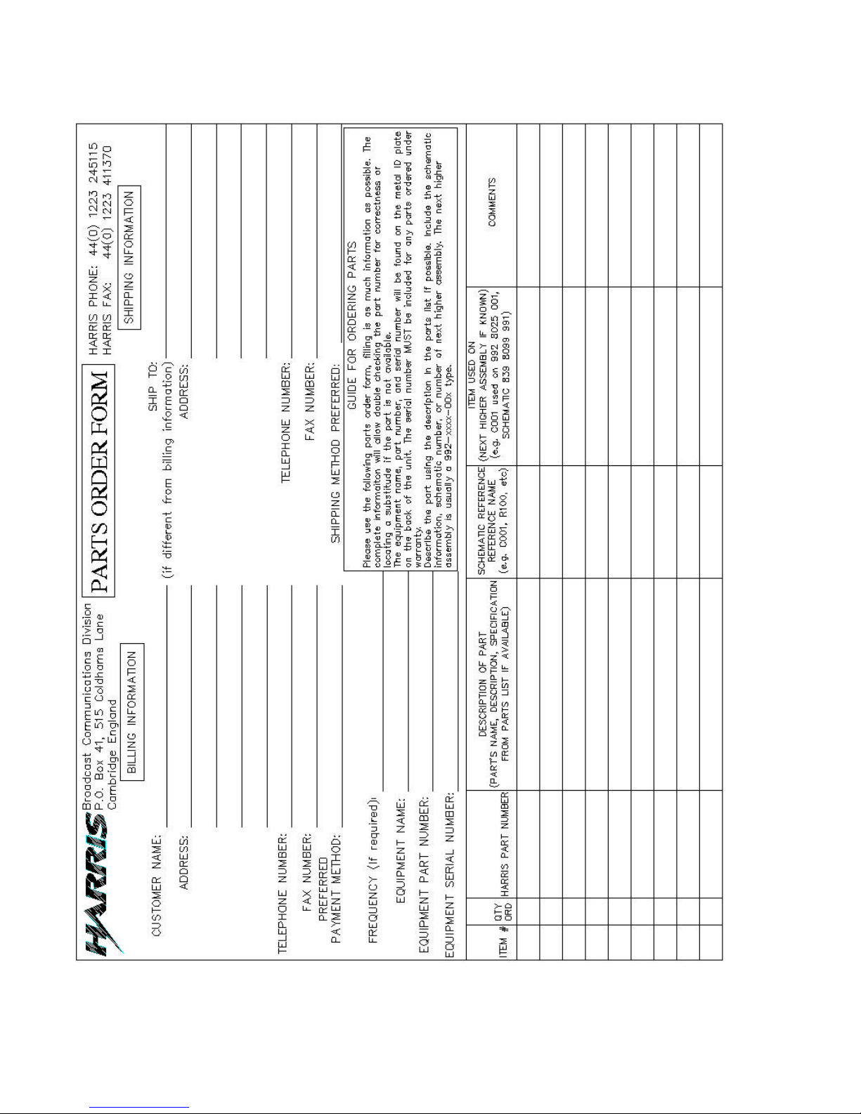
Technical Assistance and/or Replaceable Parts Service
Replacement parts are available from the HARRIS Service Parts Department.
Telephone 44 (0) 1223 245115 to contact the service parts department or address
correspondence to Service Parts Department, Broadcast Communications Division,
P.O. Box 41, 515 Coldhams Lane, Cambridge England. The HARRIS factory may
also be contacted through a FAX facility 44 (0) 1223 411370
NOTE:
The # symbol used in the parts list means used with (e.g. #C001 =
used with C001).
Page 3
Manual Revision History
Atlas Series™
REV. DATE ECN Pages Affected
Rev 0 March 04, 2002 All
Rev A May16, 2002 Released. Added installation info for cabinet combiner
reject load flow switch, page 2-7.
Rev B Sept 12, 2002 Add two pages to front pages as stated in ECO 48448:
RTTE Compliance Statement & ATLAS Declaration.
Rev C Feb 25, 2003 14045 Add parts list as seperate Acrobat file to section 7.
Add Note to section 2.13.1 to check rotation of Pump
and Fan motors.
Add paragraph 5.9 Main Controller Battery Check.
888-2473-001
WARNING: Disconnect primary power prior to servicing.
MRH-1
Page 4

888-2473-001
WARNING: Disconnect primary power prior to servicing.
MRH-2
Page 5
Guide to Using Harris Parts List Information
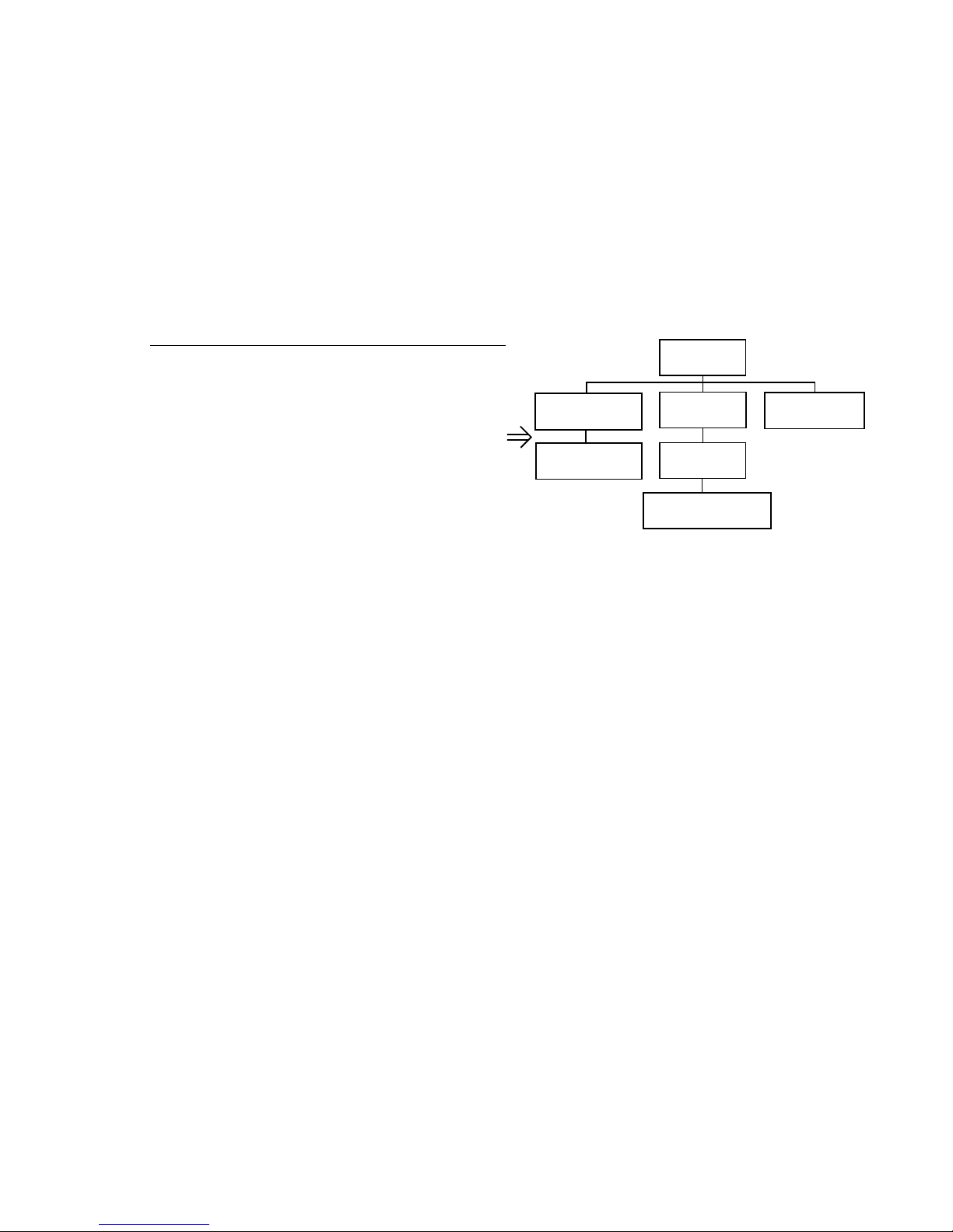
The Harris Replaceable Parts List Index portrays a tree structure with the major items being leftmost in the index. The
example below shows the Transmitter as the highest item in the tree structure. If you were to look at the bill of
materials table for the Transmitter you would find the Control Cabinet, the PA Cabinet, and the Output Cabinet. In the
Replaceable Parts List Index the Control Cabinet, PA Cabinet, and Output Cabinet show up one indentation level
below the Transmitter and implies that they are used in the Transmitter. The Controller Board is indented one level
below the Control Cabinet so it will show up in the bill of material for the Control Cabinet. The tree structure of this
same index is shown to the right of the table and shows indentation level versus tree structure level.
Example of Replaceable Parts List Index and equivalent tree structure:
Replaceable Parts List Index Part Number Page
Table 7-1. Transmitter 994 9283 001 7-2
Table 7-2. Control Cabinet 992 9244 002 7-3
Table 7-3. Controller Board 992 8344 002 7-6
Table 7-4. PA Cabinet 992 9400 002 7-7
Table 7-5. PA Amplifier 994 7894 002 7-9
Table 7-6. PA Amplifier Board 992 7904 002 7-10
Table 7-7. Output Cabinet 992 9450 001 7-12
The part number of the item is shown to the right of the description as is the page in the manual where the bill for that
part number starts. Inside the actual tables, four main headings are used:
• Table #-#. ITEM NAME - HARRIS PART NUMBER - this line gives the information that corresponds to the
• Replaceable Parts List Index entry;
• HARRIS P/N column gives the ten digit Harris part number (usually in ascending order);
• DESCRIPTION column gives a 25 character or less description of the part number;
• REF. SYMBOLS/EXPLANATIONS column 1) gives the reference designators for the item (i.e., C001, R102, etc.)
that corresponds to the number found in the schematics (C001 in a bill of material is equivalent to C1 on the schematic) or 2) gives added information or further explanation (i.e., “Used for 208V operation only,” or “Used for HT
10LS only,” etc.).
Inside the individual tables some standard conventions are used:
• A # symbol in front of a component such as #C001 under the REF. SYMBOLS/EXPLANATIONS column means
that this item is used on or with C001 and is not the actual part number for C001.
• In the ten digit part numbers, if the last three numbers are 000, the item is a part that Harris has purchased and has
not manufactured or modified. If the last three numbers are other than 000, the item is either manufactured by Harris
or is purchased from a vendor and modified for use in the Harris product.
• The first three digits of the ten digit part number tell which family the part number belongs to - for example, all elec-
trolytic (can) capacitors will be in the same family (524 xxxx 000). If an electrolytic (can) capacitor is found to have
a 9xx xxxx xxx part number (a number outside of the normal family of numbers), it has probably been modified in
some manner at the Harris factory and will therefore show up farther down into the individual parts list (because
each table is normally sorted in ascending order). Most Harris made or modified assemblies will have 9xx xxxx xxx
numbers associated with them.
The term “SEE HIGHER LEVEL BILL” in the description column implies that the reference designated part number
will show up in a bill that is higher in the tree structure. This is often the case for components that may be frequency
determinant or voltage determinant and are called out in a higher level bill structure that is more customer dependent
than the bill at a lower level.
Transmitter
994 9283 001
Control Cabinet
992 9244 002
Controller Board
992 8344 002
PA Cabinet
992 9400 002
PA Amplifier
992 7894 002
PA Amplifier Board
992 7904 002
Output Cabinet
992 9450 001
Page 6
Page 7

!
WARNING:
THE CURRENTS AND VOLTAGES IN THIS EQUIPMENT ARE DANGEROUS.
PERSONNEL MUST AT ALL TIMES OBSERVE SAFETY WARNINGS, INSTRUCTIONS AND REGULATIONS.
This manual is intended as a general guide for trained and qualified personnel who
are aware of the dangers inherent in handling potentially hazardous electrical/
electronic circuits. It is not intended to contain a complete statement of all safety
precautions which should be observed by personnel in using this or other electronic
equipment.
The installation, operation, maintenance and service of this equipment involves
risks both to personnel and equipment, and must be performed only by qualified
personnel exercising due care. HARRIS CORPORATION shall not be responsible
for injury or damage resulting from improper procedures or from the use of
improperly trained or inexperienced personnel performing such tasks. During
installation and operation of this equipment, National and local building codes and
fire protection standards must be observed.
!
WARNING:
ALWAYS DISCONNECT POWER BEFORE OPENING COVERS, DOORS, ENCLOSURES, GATES, PANELS OR SHIELDS. ALWAYS USE GROUNDING STICKS
AND SHORT OUT HIGH VOLTAGE POINTS BEFORE SERVICING. NEVER MAKE
INTERNAL ADJUSTMENTS, PERFORM MAINTENANCE OR SERVICE WHEN
ALONE OR WHEN FATIGUED.
Do not remove, short-circuit or tamper with interlock switches on access covers,
doors, enclosures, gates, panels or shields. Keep away from live circuits, know your
equipment and don’t take chances.
!
WARNING:
IN CASE OF EMERGENCY ENSURE THAT POWER HAS BEEN DISCONNECTED.
!
WARNING:
IF OIL FILLED OR ELECTROLYTIC CAPACITORS ARE UTILISED IN YOUR
EQUIPMENT, AND IF A LEAK OR BULGE IS APPARENT ON THE CAPACITOR
CASE WHEN THE UNIT IS OPENED FOR SERVICE OR MAINTENANCE, ALLOW
THE UNIT TO COOL DOWN BEFORE ATTEMPTING TO REMOVE THE DEFECTIVE CAPACITOR. DO NOT ATTEMPT TO SERVICE A DEFECTIVE CAPACITOR
WHILE IT IS HOT DUE TO THE POSSIBILITY OF A CASE RUPTURE AND SUBSEQUENT INJURY.
Page 8
Page 9

English Hereby, HARRIS Broadcast Communications declares that this
ATLAS SERIES DVB-T Transmitter is in compliance with the
essential requirements and other relevant provisions of Directive
1999/5/EC.
Finnish HARRIS Broadcast Communications vakuuttaa täten että ATLAS
SERIES DVB-T Transmitter tyyppinen laite on direktiivin 1999/5/EY
oleellisten vaatimusten ja sitä koskevien direktiivin muiden ehtojen
mukainen.
Dutch Hierbij verklaart HARRIS Broadcast Communications dat het toestel
ATLAS SERIES DVB-T Transmitter in overeenstemming is met de
essentiële eisen en de andere relevante bepalingen van richtlijn
1999/5/EG
Bij deze verklaart HARRIS Broadcast Communications dat deze
ATLAS SERIES DVB-T Transmitter voldoet aan de essentiële eisen
en aan de overige relevante bepalingen van Richtlijn 1999/5/EC.
French Par la présente HARRIS Broadcast Communications déclare que
l'appareil ATLAS SERIES DVB-T Transmitter est conforme aux
exigences essentielles et aux autres dispositions pertinentes de la
directive 1999/5/CE
Par la présente, HARRIS Broadcast Communications déclare que ce
ATLAS SERIES DVB-T Transmitter est conforme aux exigences
essentielles et aux autres dispositions de la directive 1999/5/CE qui
lui sont applicables
Swedish Härmed intygar HARRIS Broadcast Communications att denna
ATLAS SERIES DVB-T Transmitter står I överensstämmelse med
de väsentliga egenskapskrav och övriga relevanta bestämmelser
som framgår av direktiv 1999/5/EG.
Danish Undertegnede HARRIS Broadcast Communications erklærer herved,
at følgende udstyr ATLAS SERIES DVB-T Transmitter overholder
de væsentlige krav og øvrige relevante krav i direktiv 1999/5/EF
German Hiermit erklärt HARRIS Broadcast Communications, dass sich dieser/
diese/dieses ATLAS SERIES DVB-T Transmitter in
Übereinstimmung mit den grundlegenden Anforderungen und den
anderen relevanten Vorschriften der Richtlinie 1999/5/EG befindet".
(BMWi)
Hiermit erklärt HARRIS Broadcast Communications die
Übereinstimmung des Gerätes ATLAS SERIES DVB-T Transmitter
mit den grundlegenden Anforderungen und den anderen relevanten
Festlegungen der Richtlinie 1999/5/EG. (Wien)
Greek
ΜΕ ΤΗΝ ΠΑΡΟΥ_ HARRIS Broadcast Communications ∆ΗΛ_ΝΕΙ
ΟΤΙ ATLAS SERIES DVB-T Transmitter _ΥΜΜΟΡ__ΝΕΤΑΙ ΠΡΟ ΤΙ
ΟΥ_Ι_∆ΕΙ ΑΠΑΙΤΗ_ΕΙ ΚΑΙ ΤΙ ΛΟΙΠΕ _ΧΕΤΙΚΕ ∆ΙΑΤΑΞΕΙ ΤΗ
Ο∆Η_ΙΑ 1999/5/ΕΚ
Page 10

Italian Con la presente HARRIS Broadcast Communications dichiara che
questo ATLAS SERIES DVB-T Transmitter è conforme ai requisiti
essenziali ed alle altre disposizioni pertinenti stabilite dalla direttiva
1999/5/CE.
Spanish Por medio de la presente HARRIS Broadcast Communications
declara que el ATLAS SERIES DVB-T Transmitter cumple con los
requisitos esenciales y cualesquiera otras disposiciones aplicables o
exigibles de la Directiva 1999/5/CE
PortugueseHARRIS Broadcast Communications declara que este ATLAS
SERIES DVB-T Transmitter está conforme com os requisitos
essenciais e outras disposições da Directiva 1999/5/CE.
Page 11
Page 12

Page 13

Table of Contents
Section 1
Introduction
Purpose of This Manual . . . . . . . . . . . . . . . . . . . 1-1
General Description. . . . . . . . . . . . . . . . . . . . . . . 1-2
Atlas Series™ Transmitter Models . . . . . . . . . 1-3
System Block Diagrams . . . . . . . . . . . . . . . . . . 1-4
Transmitter Control System . . . . . . . . . . . . . . . 1-6
Graphical User Interface . . . . . . . . . . . . . . . . 1-6
Control System Communications . . . . . . . . . 1-7
In-System Programming or ISP. . . . . . . . . . . 1-7
Remote Control . . . . . . . . . . . . . . . . . . . . . . . 1-7
PA Module . . . . . . . . . . . . . . . . . . . . . . . . . . . . 1-8
Module Control . . . . . . . . . . . . . . . . . . . . . . . 1-9
Power Supplies. . . . . . . . . . . . . . . . . . . . . . . . . 1-9
Cooling System. . . . . . . . . . . . . . . . . . . . . . . . 1-10
Cooling System Control Panel. . . . . . . . . . . 1-10
Pump Module. . . . . . . . . . . . . . . . . . . . . . . . 1-11
Heat Exchanger . . . . . . . . . . . . . . . . . . . . . . 1-12
Transmitter Cold Plates . . . . . . . . . . . . . . . . 1-12
V-XCAST™ Exciter . . . . . . . . . . . . . . . . . . . 1-13
General Specifications. . . . . . . . . . . . . . . . . . . . 1-14
Section 2
Installation / Initial Turn-On
Introduction. . . . . . . . . . . . . . . . . . . . . . . . . . . . . 2-1
Documentation . . . . . . . . . . . . . . . . . . . . . . . . . . 2-1
Installation Drawings . . . . . . . . . . . . . . . . . . . . 2-2
Installation Checkboxes . . . . . . . . . . . . . . . . . . . 2-3
Transmitter Cabinet Placement. . . . . . . . . . . . . . 2-3
Cooling System Installation . . . . . . . . . . . . . . . . 2-4
Transmitter AC Connection . . . . . . . . . . . . . . . . 2-7
Second PA Cabinet Interconnections . . . . . . . . 2-10
Signal and Ground Connections . . . . . . . . . . . . 2-11
External Interlock Connections. . . . . . . . . . . . . 2-11
Cabinet Combiner Connections
(DVL 4300 and 5700 only) . . . . . . . . . . . . . . . 2-12
RF Sample Connections . . . . . . . . . . . . . . . . . 2-12
3 Port U-Link Panel Connections . . . . . . . . . . . 2-13
Install PA and PS Modules . . . . . . . . . . . . . . . . 2-14
Initial Turn-On . . . . . . . . . . . . . . . . . . . . . . . . . 2-15
Cooling System Turn ON. . . . . . . . . . . . . . . . 2-17
Setting the Transmitter Flow Rate. . . . . . . . 2-18
Setting the Test Load Flow Switch Trip
Level. . . . . . . . . . . . . . . . . . . . . . . . . . . . . . 2-18
Setting the Heat Exchanger Fan Turn ON
Temperatures . . . . . . . . . . . . . . . . . . . . . . . 2-19
Verifying Pump Switching . . . . . . . . . . . . . 2-19
Local Pump Operation. . . . . . . . . . . . . . . . . 2-20
Setting Exciter Parameters . . . . . . . . . . . . . . . 2-20
RF Initial Turn ON . . . . . . . . . . . . . . . . . . . . .2-22
Cabinet Phasing. . . . . . . . . . . . . . . . . . . . . . . .2-23
Parallel Remote Control Connections . . . . . . . .2-24
Transmitter Control Functions, J13 and J14 . .2-25
Remote Status Outputs, J15 & J16. . . . . . . . . . .2-26
Remote Power Metering, J17 . . . . . . . . . . . . . 2-27
Section 3
Operation
Introduction . . . . . . . . . . . . . . . . . . . . . . . . . . . . . 3-1
Transmitter Control Panel . . . . . . . . . . . . . . . . . .3-1
Main Menu "Quick" Buttons. . . . . . . . . . . . . . .3-2
Graphical User Interface (GUI) . . . . . . . . . . . . . . 3-2
Global Status and Navigation . . . . . . . . . . . . . .3-3
GUI Home Page. . . . . . . . . . . . . . . . . . . . . . . . . .3-4
Drive Chain Main Menu . . . . . . . . . . . . . . . . . . .3-6
Drive Chain Faults . . . . . . . . . . . . . . . . . . . . . . .3-7
Drive Meters . . . . . . . . . . . . . . . . . . . . . . . . . . . 3-8
Drive Service. . . . . . . . . . . . . . . . . . . . . . . . . . .3-8
Exciter Setup. . . . . . . . . . . . . . . . . . . . . . . . . .3-9
DCU Setup . . . . . . . . . . . . . . . . . . . . . . . . . . 3-12
Power Amp Main Menu . . . . . . . . . . . . . . . . . . .3-13
PA Faults . . . . . . . . . . . . . . . . . . . . . . . . . . . . .3-14
PA Meters . . . . . . . . . . . . . . . . . . . . . . . . . . . .3-15
PA Service. . . . . . . . . . . . . . . . . . . . . . . . . . . .3-16
PA Module Removal. . . . . . . . . . . . . . . . . . .3-16
PA Module Alignment . . . . . . . . . . . . . . . . .3-17
Output Main Menu. . . . . . . . . . . . . . . . . . . . . . .3-18
Output Faults . . . . . . . . . . . . . . . . . . . . . . . . . . 3-19
Output Meters . . . . . . . . . . . . . . . . . . . . . . . . .3-20
Output Service. . . . . . . . . . . . . . . . . . . . . . . . .3-20
PA Reject Service. . . . . . . . . . . . . . . . . . . . .3-21
Output Setup . . . . . . . . . . . . . . . . . . . . . . . . .3-22
Power Supply Main Menu . . . . . . . . . . . . . . . . .3-23
PS Faults . . . . . . . . . . . . . . . . . . . . . . . . . . . . .3-24
PS Meters. . . . . . . . . . . . . . . . . . . . . . . . . . . . .3-24
PS Service . . . . . . . . . . . . . . . . . . . . . . . . . . . .3-25
System Main Menu . . . . . . . . . . . . . . . . . . . . . .3-26
System Control . . . . . . . . . . . . . . . . . . . . . . . .3-27
System Cooling . . . . . . . . . . . . . . . . . . . . . . . . 3-28
Cooling System Control Panel . . . . . . . . . . .3-28
Cooling Faults. . . . . . . . . . . . . . . . . . . . . . . . 3-29
Cooling Meters . . . . . . . . . . . . . . . . . . . . . . .3-29
Cooling Service. . . . . . . . . . . . . . . . . . . . . . . 3-30
System Log . . . . . . . . . . . . . . . . . . . . . . . . . . .3-31
System Service . . . . . . . . . . . . . . . . . . . . . . . . 3-32
System Setup. . . . . . . . . . . . . . . . . . . . . . . . .3-33
Software Revisions (SW REVs). . . . . . . . . .3-36
GUI Menu Structures. . . . . . . . . . . . . . . . . . . . .3-37
Page 14

Table of Contents (continued)
Section 4
Theory of Operation
Introduction. . . . . . . . . . . . . . . . . . . . . . . . . . . . . 4-1
Active Logic Symbols . . . . . . . . . . . . . . . . . . . 4-2
Block Diagram Descriptions. . . . . . . . . . . . . . . . 4-2
Transmitter Control System . . . . . . . . . . . . . . . . 4-3
Micro Module. . . . . . . . . . . . . . . . . . . . . . . . . . 4-4
CPLD, Complex Programmable Logic Device 4-5
I/O Expansion . . . . . . . . . . . . . . . . . . . . . . . . 4-5
Life Support Backup . . . . . . . . . . . . . . . . . . . 4-5
Controller Area Network (CAN) Bus. . . . . . . . 4-6
System Control Bus . . . . . . . . . . . . . . . . . . . . . 4-7
CAN Bus . . . . . . . . . . . . . . . . . . . . . . . . . . . . 4-7
Parallel Control Lines . . . . . . . . . . . . . . . . . . 4-7
Main Controller . . . . . . . . . . . . . . . . . . . . . . . . 4-9
Transmitter Control . . . . . . . . . . . . . . . . . . . . 4-9
RS-232 Serial Connections . . . . . . . . . . . . . 4-10
Life Support Mode, Main Controller. . . . . . 4-10
Manual RF MUTE. . . . . . . . . . . . . . . . . . . . 4-11
External I/O Board . . . . . . . . . . . . . . . . . . . . . 4-11
External Interlocks. . . . . . . . . . . . . . . . . . . . 4-13
RF Mute Interlock . . . . . . . . . . . . . . . . . . . . 4-14
Transmitter RF System . . . . . . . . . . . . . . . . . . . 4-15
V-XCAST Exciter(s) . . . . . . . . . . . . . . . . . . . 4-15
Drive Control Unit (DCU) . . . . . . . . . . . . . . . 4-15
Backplane Interface Board. . . . . . . . . . . . . . . 4-16
RF Splitter . . . . . . . . . . . . . . . . . . . . . . . . . . 4-16
Control Distribution. . . . . . . . . . . . . . . . . . . 4-16
Low Voltage Power Supply Distribution. . . 4-17
PA Module . . . . . . . . . . . . . . . . . . . . . . . . . . . 4-17
Phase and Gain Board . . . . . . . . . . . . . . . . . 4-18
Automatic Level Control (ALC) . . . . . . . . . 4-19
RF Pallets. . . . . . . . . . . . . . . . . . . . . . . . . . . 4-20
Auto Bias Circuit . . . . . . . . . . . . . . . . . . . . . 4-20
Pallet Splitters and Combiner . . . . . . . . . . . 4-21
DC Distribution Board . . . . . . . . . . . . . . . . . 4-21
Module Controller . . . . . . . . . . . . . . . . . . . . 4-21
PA Module Combiner . . . . . . . . . . . . . . . . . . . 4-22
Combiner Isolation Loads . . . . . . . . . . . . . . 4-25
RF Monitor Board . . . . . . . . . . . . . . . . . . . . . 4-26
RF Detectors . . . . . . . . . . . . . . . . . . . . . . . . 4-27
Reject Load RF Detector (Relative) . . . . . . 4-28
Precision RF Power Detectors . . . . . . . . . . . 4-30
Normal Mode / Life Support Mode . . . . . . . 4-30
Power Supplies . . . . . . . . . . . . . . . . . . . . . . . . . 4-31
AC Input. . . . . . . . . . . . . . . . . . . . . . . . . . . . . 4-31
PA Power Supply Modules. . . . . . . . . . . . . . . 4-31
Low Voltage Power Supplies (LVPS) . . . . . . 4-32
Power Supply Monitor Board . . . . . . . . . . . . .4-32
S1, PS Monitor Board Config Switches . . . .4-33
LVPS Interface and Cabinet ID . . . . . . . . . .4-34
PA Power Supply Monitoring and Control. .4-34
AC Line Monitoring . . . . . . . . . . . . . . . . . . .4-35
Cabinet Cooling System Sensors . . . . . . . . . 4-35
Cooling System . . . . . . . . . . . . . . . . . . . . . . . . .4-39
Pump Module . . . . . . . . . . . . . . . . . . . . . . . . .4-39
Heat Exchanger . . . . . . . . . . . . . . . . . . . . . . . .4-40
Transmitter Cold Plates. . . . . . . . . . . . . . . . . .4-40
Pump Control Panel. . . . . . . . . . . . . . . . . . . . .4-40
Transmitter Interconnect. . . . . . . . . . . . . . . .4-41
Front Panel Controls. . . . . . . . . . . . . . . . . . .4-41
Control Voltage Power Supply. . . . . . . . . . .4-42
Control Description. . . . . . . . . . . . . . . . . . . .4-42
Section 5
Maintenance and Alignments
Introduction . . . . . . . . . . . . . . . . . . . . . . . . . . . . . 5-1
PA Module Removal and Replacement. . . . . . . .5-1
PA Module Removal. . . . . . . . . . . . . . . . . . . . . 5-2
Installing a PA Module . . . . . . . . . . . . . . . . . . .5-3
PA Module Auto Bias Procedure. . . . . . . . . . . . .5-4
PA Module Phasing . . . . . . . . . . . . . . . . . . . . . . .5-5
Phase Control Voltage. . . . . . . . . . . . . . . . . . . .5-5
Module Phasing Procedure . . . . . . . . . . . . . . . .5-6
Power Calibrations. . . . . . . . . . . . . . . . . . . . . . . . 5-7
Forward Power Calibration . . . . . . . . . . . . . . . .5-8
Reflected Power Calibration . . . . . . . . . . . . . . .5-8
DCU Calibration . . . . . . . . . . . . . . . . . . . . . . . .5-9
LCD Contrast Adjustment . . . . . . . . . . . . . . . . .5-10
Touch Screen Calibration. . . . . . . . . . . . . . . . . .5-11
V-XCAST Exciter adjustments . . . . . . . . . . . . .5-12
Main Controller Battery Check . . . . . . . . . . . . .5-12
Section 6
Diagnostics
Introduction . . . . . . . . . . . . . . . . . . . . . . . . . . . . . 6-1
GUI System Log . . . . . . . . . . . . . . . . . . . . . . . . .6-2
Fault Tables . . . . . . . . . . . . . . . . . . . . . . . . . . . . .6-3
Parts List
Parts List Index . . . . . . . . . . . . . . . . . . . . . . . . . .7-1
Page 15

2/25/03 888-2473-001 1-1
WARNING: Disconnect primary power prior to servicing.
ATLAS Series™
Section 1
Introduction
1
1.1 Purpose of This Manual
This technical manual contains the information pertaining to the Atlas™ Series
UHF solid-state DTV transmitter. The various sections of this technical manual
provide the following types of information.
• Section 1, Introduction, provides general manual layout, frontispiece, equipment
description, block diagram and general specifications.
• Section 2, Installation/Initial Turn-On, provides physical and electrical installa-
tion procedures for the transmitter, cooling and RF systems and basic remote
control connections.
• Section 3, Operation, provides operation and navigation information for the
Graphical User Interface or GUI as well as identification and functions of all
external panel controls and indicators.
• Section 4, Theory of Operation, provides detailed theory of operation for the
transmitter and sub-assemblies.
• Section 5, Maintenance and Alignments, provides preventative and corrective
maintenance information and all field alignment procedures.
• Section 6, Diagnostics, provides detailed fault information and diagnostic proce-
dures to the board level.
• Section 7, Parts List, provides a parts list for the overall transmitter as well as
individual modules.
Page 16
1-2 888-2473-001 2/25/03
WARNING: Disconnect primary power prior to servicing.
Section 1 Introduction ATLAS Series™
1.2 General Description
This section contains a general description of the Atlas Series™ series television
transmitters. Included in this section will be descriptions of the Control System,
Power Amplifier, block diagrams of the different models and system specifications.
The Atlas Series™ DTV transmitter consists of one or two cabinets depending on
power level. See Table 1-1 for a listing of the available models and power levels.
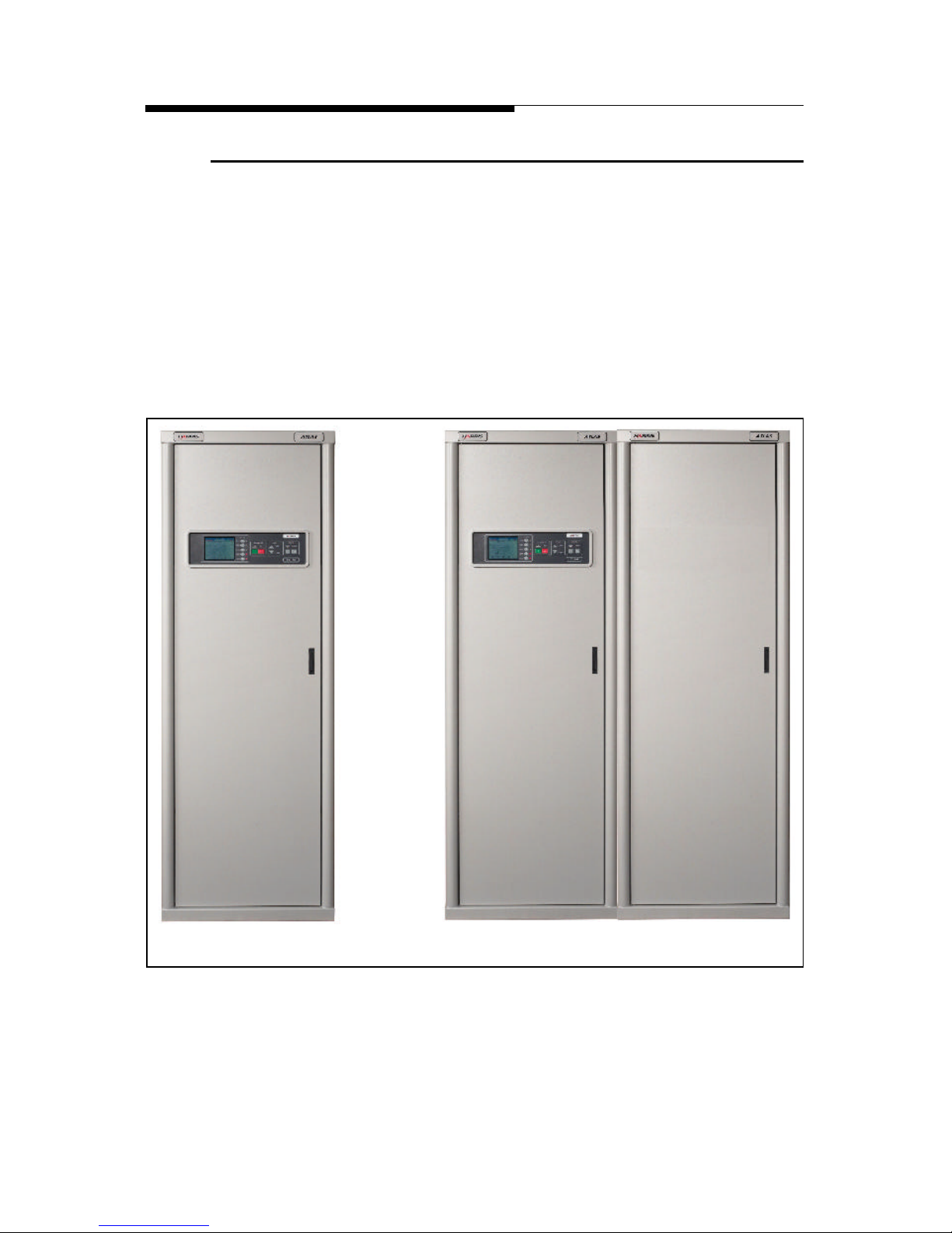
Figure 1-1 shows the 2 possible cabinet configurations. The cabinet on the left is for
power levels up to 3kW, with the dual cabinet configuration on the right allowing
for 4.3kW and 5.7kW versions.
Figure 1-1 Transmitter Front View
All Models up to 3kW
DVL 4300 and DVL 5700
(4.3kW and 5.7kW Models)
DVL 400 - DVL 3000
Page 17

2/25/03 888-2473-001 1-3
WARNING: Disconnect primary power prior to servicing.
Section 1 Introduction
ATLAS Series™
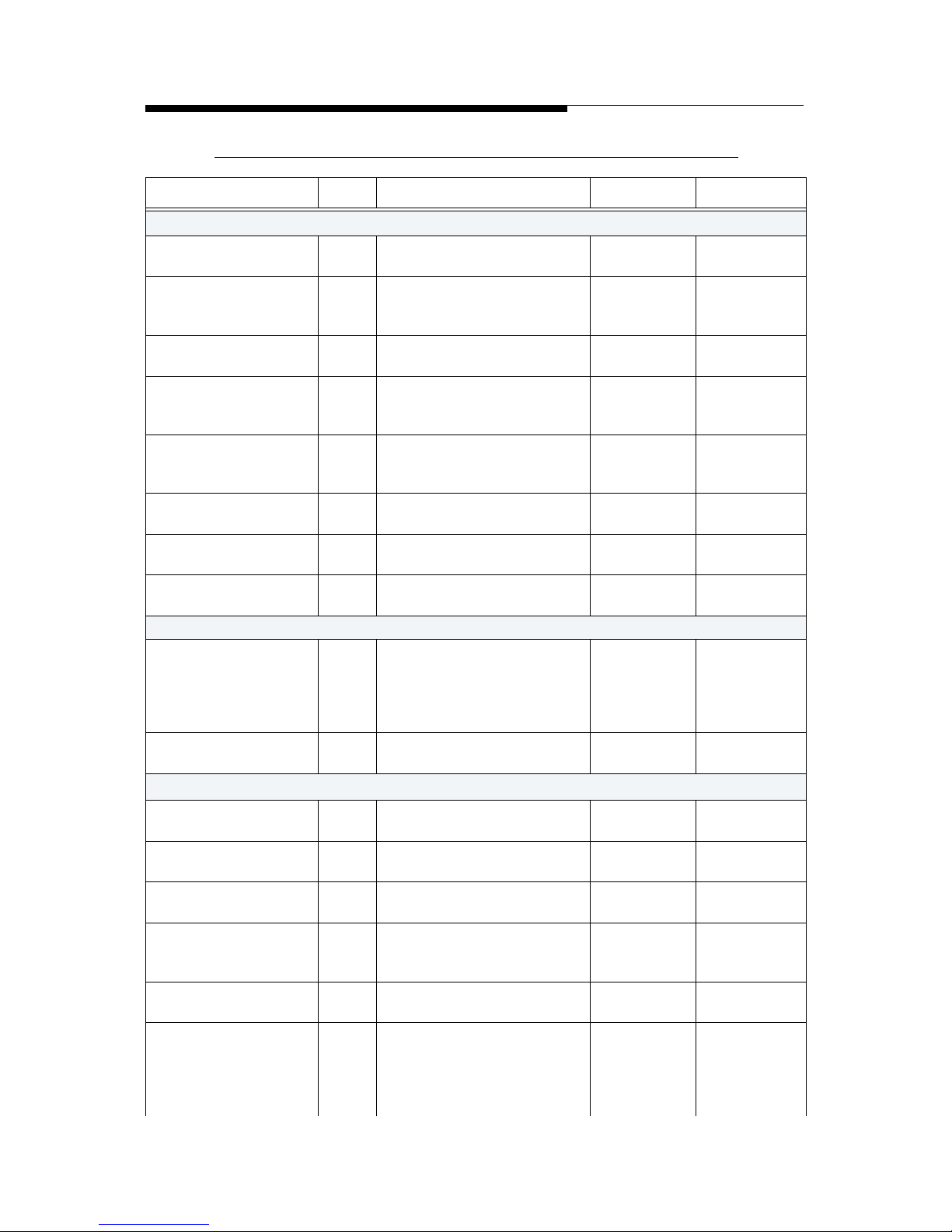
1.2.1 Atlas Series™ Transmitter Models
The Atlas Series™ UHF transmitter is available in 8 liquid cooled power levels, not
including dual transmitter configurations. The available models are listed below in
Table 1-1.
Table 1-1 Atlas Series™ Transmitter Models
Tx Models Cabinets PA Modules Output Power Primary Cooling
DVL 400 1 1 400W LIQUID
DVL 800 1 2 800W LIQUID
DVL 1100 1 3 1.1kW LIQUID
DVL 1500 1 4 1.5kW LIQUID
DVL 2200 1 6 2.2kW LIQUID
DVL 3000 1 8 3.0kW LIQUID
DVL 4300 2 12 (6 per cabinet) 4.3kW LIQUID
DVL 5700 2 16 (8 per cabinet) 5.7kW LIQUID
NOTE: All power levels given in Average power.
Page 18
1-4 888-2473-001 2/25/03
WARNING: Disconnect primary power prior to servicing.
Section 1 Introduction ATLAS Series™
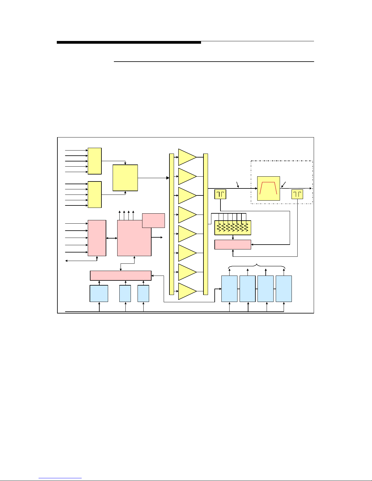
1.2.2 System Block Diagrams
The following figures contain System block diagrams showing the basic signal flow
and configuration for each Atlas Series™ Transmitter Model. Figure 1-2 shows the
Medium Power single cabinet system with up to 8 PA modules. Note that a driver is
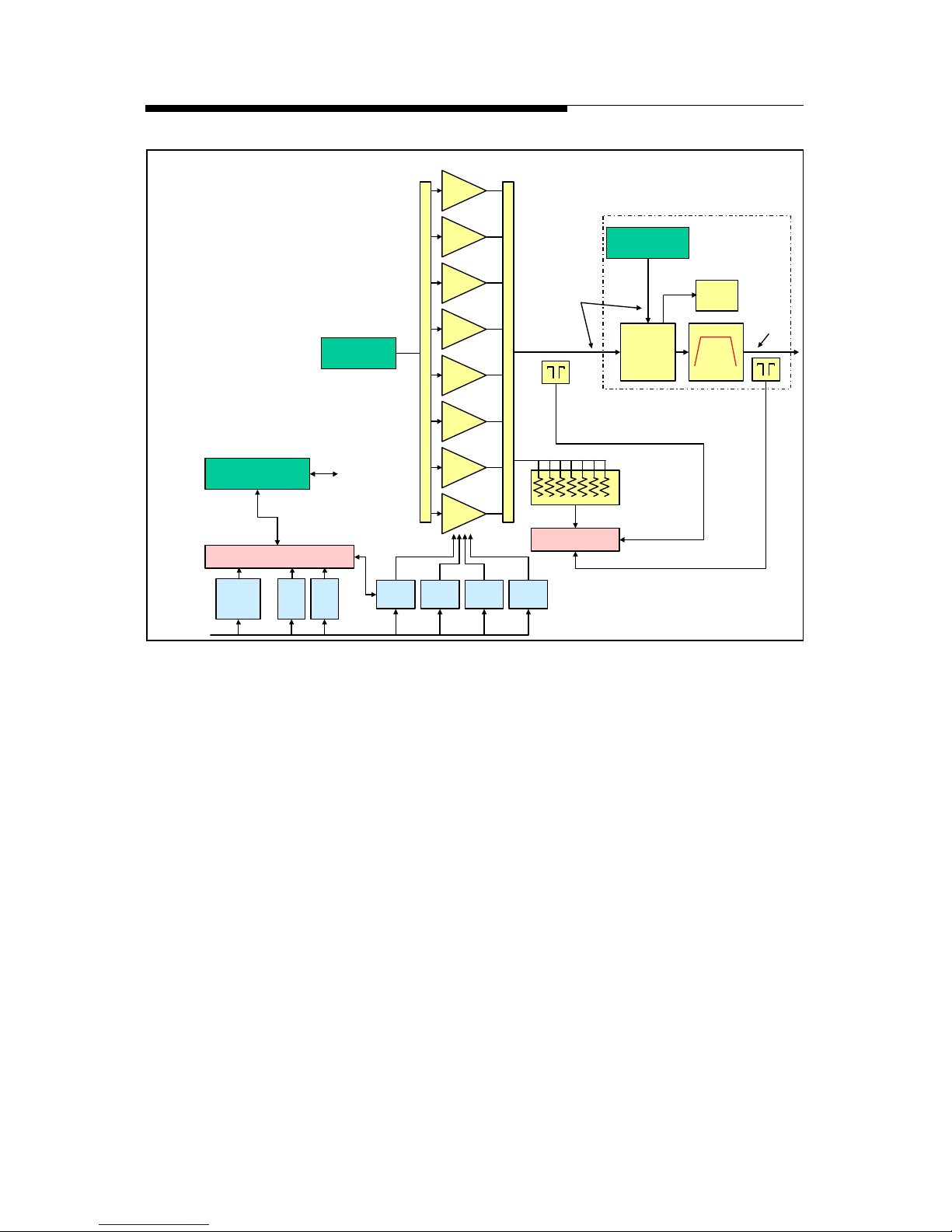
not needed, as the exciter power is sufficient to drive up to 8 PA modules. Figure 13 shows the High Power configuration which is simply the addition of a second
cabinet and a cabinet combiner for outputs of 4.3Kw and 5.7kW.
Figure 1-2 Atlas Series™ Medium Power System Block Diagram
400W up to 3kW (DVL 3000 shown)
Exciter AExciter B
Drive
Control
Unit
RF Monitor
DVB
Filter
Reject
Loads
PA 1
PA 2
PA 3
PA 4
PA 5
PA 6
PA 7
PA 8
PS 1
32V
PS 2
32V
PS 3
32V
PS 4
32V
Ext
I/O
Board
Main
Controller
&
Life Support
MOV
Board
LVPS
LVPS
AC Power
380/400/415
VAC 3-Phase
or
220/240
Single Phase
To PA Modules
Bus to 2nd PA
TCP/IP
RS-232
Parallel
Ext Interlocks
Pump Control
ASI-1
ASI-2
10MHz
GPS
1 PPS
ASI-1
ASI-2
10MHz
GPS
1 PPS
1-5/8” Line
Model: DVL 3000
3.4kW 3.0kW
460W
460W
460W
460W
460W
460W
460W
460W
Power Supply Monitor
PS Control and Monitoring
Graphical
User
Interface
RF Samples
Note: This represents Cabinet #1
for the DVL 4300 and 5700
RF Splitter
RF Combiner
PA Cabinet FWD and RFLD
Total System FWD and RFLD
These Components are outside
the Transmitter Cabinet
Page 19
2/25/03 888-2473-001 1-5
WARNING: Disconnect primary power prior to servicing.
Section 1 Introduction
ATLAS Series™
Figure 1-3 Atlas Series™ High Power System Block Diagram
DVL 4300 or DVL 5700 (shown)
RF Monitor
Cabinet
Combiner
Reject
Loads
PS 1
32V
PS 2
32V
PS 3
32V
PS 4
32V
MOV
Board
LVPS
LVPS
AC Power
380/400/415
VAC 3-Phase
5.7kW
RF Samples
Power Supply Monitor
Model: DVL 5700
Cabinet #2
RF Drive from
Cabinet #1
RF Output from
Cabinet #1
3.4kW
DVB
Filter
Control PS Bus from
Cabinet #1
Note: For DVL 4300
Omit PAs 7 & 8 and PS #4
To PA Modules
and RF Monitor
These
Components are
outside the
transmitter cabinet
PA Cabinet FWD and RFLD
Total System FWD and RFLD
PA 1
PA 2
PA 3
PA 4
PA 5
PA 6
PA 7
PA 8
460W
460W
460W
460W
460W
460W
460W
460W
RF Splitter
RF Combiner
Reject
Load
Page 20

1-6 888-2473-001 2/25/03
WARNING: Disconnect primary power prior to servicing.
Section 1 Introduction ATLAS Series™
1.2.3 Transmitter Control System
The transmitter uses a distributed architecture control system. This means that each
transmitter sub-system is responsible for its own monitoring and protection and
simply reports back to the Main Controller for display on the GUI (Graphical User
Interface) or to a remote interface. The heart of the system is the 376 Micro Module
which is used in all of the transmitter systems for control, monitoring and
protection. The Micro Module is used on each of the following controllers and subsystems:
a. Main Controller Board - This board is responsible for transmitter control and
monitoring. However, with the distributed control architecture, it is not
directly responsible for protection of the individual transmitter components. It
merely gathers all status and fault data from the individual sub-systems and
reports that information to the operator. The Main Controller is responsible
for system level control (issues which effect multiple systems) since it is the
only part of the control system which can monitor the entire transmitter.
b. Module Controllers (1 in each module) - Responsible for protection and con-
trol of the PA Module. Report directly to the Main Controller Board.
c. RF Monitor Board - Responsible for cabinet VSWR protection and monitor-
ing of combiner reject loads. Reports directly to the Main Controller.
d. Power Supply Monitor Board - Responsible for control and monitoring of the
PA power supplies and distribution of the low voltage. Also responsible for
monitoring the cooling system including temperature, flow and leaks. Reports
directly to the Main Controller.
e. External I/O Board - Provides all customer interface connections including
parallel remote control and serial remote control. Reports directly to the Main
Controller.
1.2.3.1 Graphical User Interface
The front panel user interface is a 1/4 VGA, LCD touchscreen display. The
touchscreen display uses software buttons to monitor the transmitter. Hardware
buttons for the primary transmitter functions such as ON, OFF, RAISE and
LOWER are provided on the overlay panel next to the display.
Page 21

2/25/03 888-2473-001 1-7
WARNING: Disconnect primary power prior to servicing.
Section 1 Introduction
ATLAS Series™
1.2.3.2 Control System Communications
The control system uses a serial communications system called a CAN bus. CAN
stands for Controller Area Network. The CAN bus is a closed loop serial network
operated by the Main Controller Board. Each circuit board and module connected to
the CAN bus is considered a node and therefore has a specific address. This allows
the Main Controller to gather information from all parts of the transmitter and
display it on the GUI. One big advantage of the CAN bus is that it requires only 2
wires of the system control ribbon cable, eliminating a large amount of discrete
wiring which would otherwise be required.
For redundancy, the CAN bus is backed up by parallel, hardwired, control lines that
allow the transmitter to stay on the air even if the CAN bus fails. The parallel
control lines also provide the instantaneous OFF and RF MUTE commands
necessary for transmitter protection.
1.2.3.3 In-System Programming or ISP
The use of the CAN bus for communication between the various Micro Modules in
the transmitter also allows for easy updating of the software used in each transmitter
sub-system via a serial port connection to an external computer. This is referred to
as In-System Programming or ISP.
The real benefit of In-System Programming is that it allows any or all of the
transmitter software to be updated without removing or replacing any firmware ICs.
The Harris ISP program is provided on the CD-ROM accompanying this manual
along with all of the transmitter software as it shipped from the factory. The Harris
ISP program is easy to use and it only takes a few minutes to load or update
software.
NOTE:
Software does not need to be loaded into the transmitter unless new components are installed or an update is sent from Harris. The transmitter, as
shipped from the factory, is preloaded and ready to run.
1.2.3.4 Remote Control
The Atlas Series™ transmitter has the basic Discrete wired parallel remote control
with the standard connections for control, status and analogue monitoring. A
network interface will be available by mid year 2002, but this will be an optional
add-on deivce.
Page 22

1-8 888-2473-001 2/25/03
WARNING: Disconnect primary power prior to servicing.
Section 1 Introduction ATLAS Series™
1.2.4 PA Module
The Atlas Series™ PA Module utilises LDMOS amplifiers to produce up to 460W
average power output. Each module weighs approximately 20.5kg and can be unplugged while the transmitter is running. A single cabinet Atlas Series™ transmitter
can have 1, 2, 3, 4, 6 or 8 PA modules to achieve the various power levels shown in
Table 1-1. The 2 cabinet version will have either 6 or 8 modules per cabinet. A
block diagram of the PA module is shown in Figure 1-4.
Each PA module consists of the following components:
a. PA Module Controller Board - Responsible for all monitoring and protection
of the module. Reports to the transmitter Main Controller via the CAN bus
but is also connected to the parallel control lines in case the CAN bus is not
operational.
b. Phase and Gain Board - Provides for module phase and gain adjustments to
minimise module combiner reject power. Also provides for cabinet phasing
for the 2 cabinet transmitters to minimise cabinet combiner reject power.
c. DC Distribution Board - Provides FET switching of the +32Vdc and sensing
of driver and pallet currents.
d. Pre-driver Pallet - Provides enough power to drive the 2 way splitter and the 2
driver pallets.
e. Two (2) LDMOS Driver Pallets - Provide enough power to drive the 4 way
splitters and the inputs to the power amplifier pallets.
f. Pallet Splitter and Combiner - Actually two 4-way splitters and one 8-way
combiner.
g. Eight (8) LDMOS Amplifier Pallets - When combined, they provide up to
460 watts of average power at the output of the module.
h. Liquid Cooled Cold Plate - Mounted directly to the 8 LDMOS power ampli-
fier pallets for cooling.
i. RF Output Directional Coupler - Samples both Forward and Reflected power
for metering, module ALC and module VSWR protection.
Each Atlas Series™ PA Module is a self-contained 460W transmitter (except for the
power supply) with its own internal control, monitoring and protection. The
modules only receive basic On/Off, Mute, Restart, Phase and Gain commands from
the transmitter control system. This means that each module will protect itself
without relying on the system controller.
Page 23
2/25/03 888-2473-001 1-9
WARNING: Disconnect primary power prior to servicing.
Section 1 Introduction
ATLAS Series™
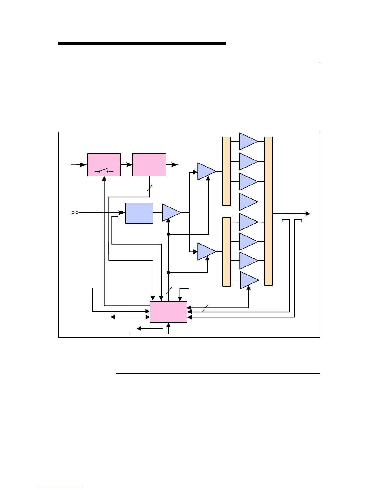
1.2.4.1 Module Control
The primary method for control and monitoring of the PA Modules is by the serial
CAN (Controller Area Network) Bus. It is used for control, status and monitoring of
all PA Module parameters and for the reporting of Module faults. As a backup to
this serial control network, each PA Module has dedicated hardware control lines
for functions such as On, Off, Restart and RF Mute.
Figure 1-4 PA Module Block Diagram
1.2.5 Power Supplies
Up to four +32 Vdc power supplies are used to provide the DC voltage to the PA
modules within each PA cabinet. Each power supply provides power to two PA
modules. Module power supplies are designed to allow removal and insertion of one
unit while the remaining power supplies are operating. The control system in the PA
Cabinet is powered by a single low voltage power. A second (redundant) low
voltage power supply is optional.
AB
PHASE
&
GAIN
CONTROL
BOARD
SS RELAY
AB
AB
AB
AB
AB
AB
A
FWD
TEMP
Pin
+32V
BIAS
RF IN
TO MAIN CONTROLLER
SWITCHED
+32V
ON/OFF
MODULE ENABLE/DISABLE
32V
MON
RF
OUT
AB
AB
AB
Auto Biasing
Pre-driver
Driver A
Driver B
8
CURRENT
SENSING
Pallets
Pallet Combiner
SplitterSplitter
BIAS
BIAS
3
12
RFL
CAN Bus
Page 24
1-10 888-2473-001 2/25/03
WARNING: Disconnect primary power prior to servicing.
Section 1 Introduction ATLAS Series™
1.2.6 Cooling System
The Atlas Series™ transmitter uses a 50/50 glycol liquid cooling system to remove
the majority of the heat away from the transmitter but also has cabinet flushing fans
to remove residual cabinet heat. A simplified block diagram of the liquid cooling
system is shown in Figure 1-6. A simplified diagram of the liquid cooling system
inside the transmitter cabinet is shown in Figure 1-7. The cooling system basically
consists of:
a. Cooling System Control Panel
b. Pump Module
c. Heat Exchanger
d. Transmitter Cold Plates
1.2.6.1 Cooling System Control Panel
The cooling system control panel controls the pump module and the heat exchanger
and is the interface to the transmitter control system. It uses very basic relay logic
for reliable operation. The cooling system control panel is connected to the External
I/O board in the Atlas Transmitter for monitoring and control. It also supplies ac
power to the pump module and the heat exchanger and interfaces the fault and status
information from these units to the transmitter.
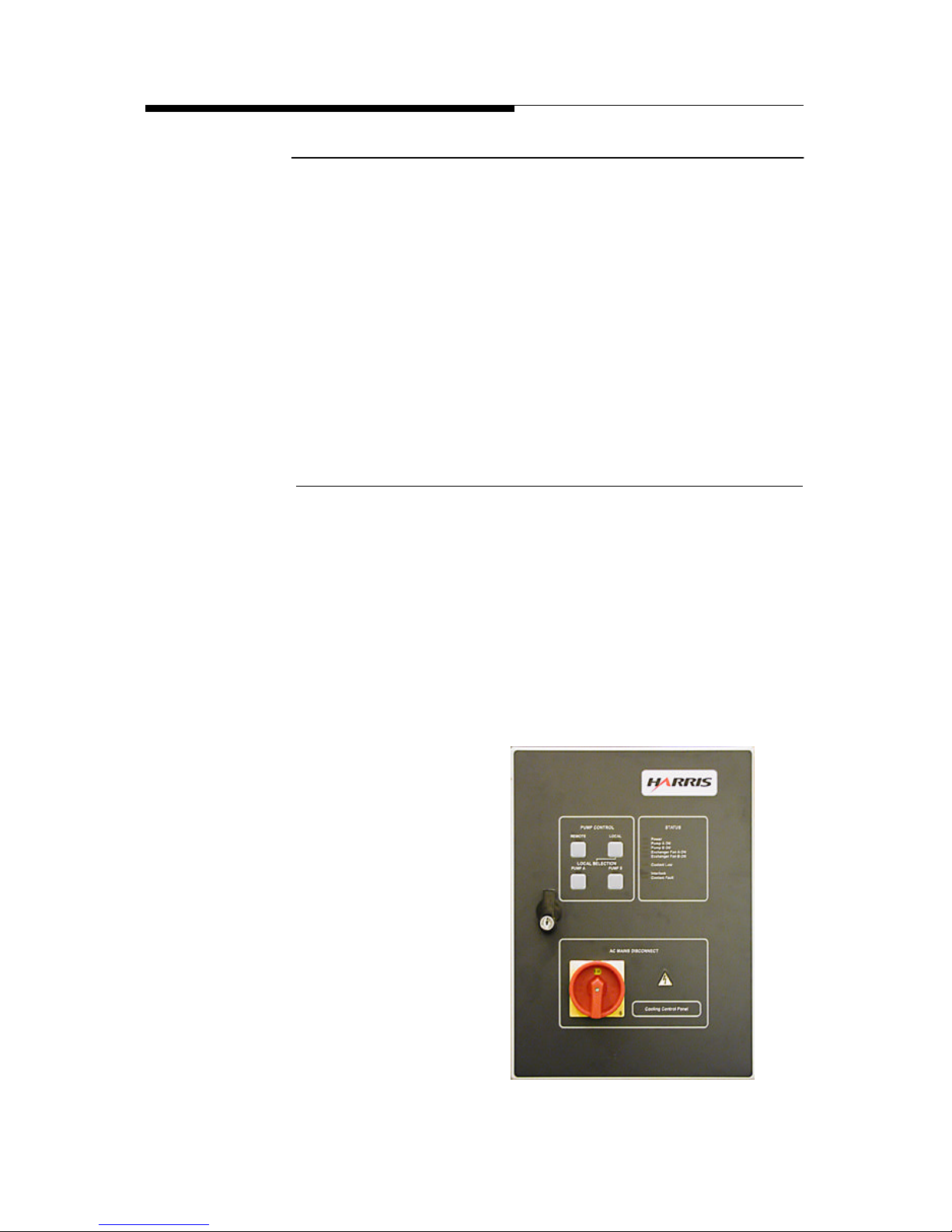
The cooling system control panel, shown in Figure 1-5 below, has local controls on
the front which allow manual selection of pump A or optional pump B and selection
of Remote/Local control. It also has the following status indicators:
• Remote
• Local
• Interlock
• Fan A ON
• Fan B ON
• *Pump A ON
• *Pump B ON
• Pump A Preset
• Pump B Preset
• *Coolant Fault
• *Coolant Low
• Power
Figure 1-5 Cooling System Control Panel
Page 25
2/25/03 888-2473-001 1-11
WARNING: Disconnect primary power prior to servicing.
Section 1 Introduction
ATLAS Series™
* Each of these status indications is also sent to the transmitter for display on the
GUI and via remote control.
When in Remote mode, the transmitter is responsible for control of the cooling
system, including ON/OFF, manual pump selection and automatic pump switching
in the case of a failure. Placing the control panel in Local mode allows manual
switching of the pumps using the pump select buttons on the cooling control panel.
The lower half of the control panel contains the ac isolation switch which
disconnects ac power from the pump module and heat exchanger as well as the
control circuitry in the control panel itself.
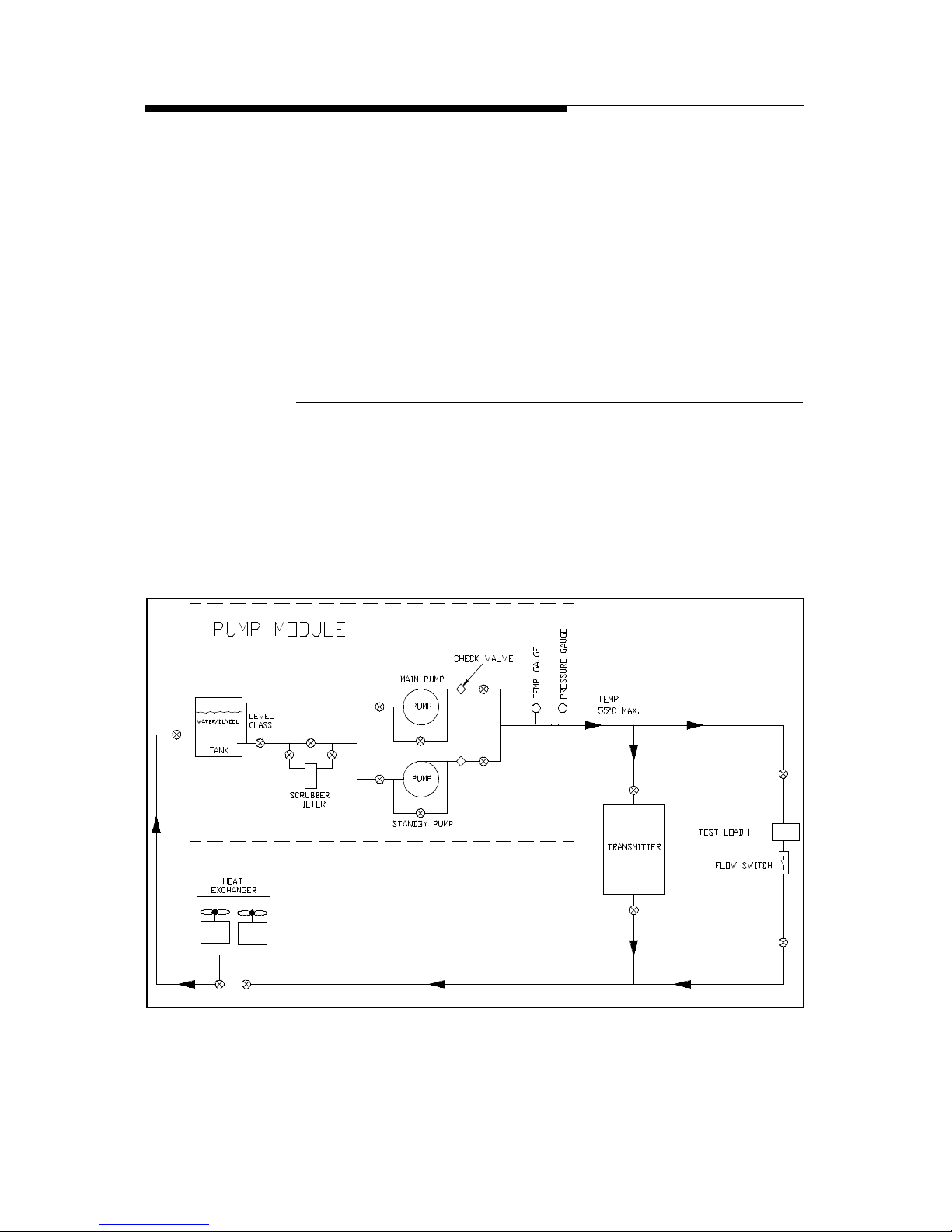
1.2.6.2 Pump Module
The pump module is a self-contained unit with a storage tank, pressure and
temperature gauges, a strainer filter and one pump or the optional dual pumps
operating in main/standby mode. The pump module is an open frame unit and is
meant to be installed inside the building (with a special option for outside
mounting). The control panel is separate from the pump module and should be
mounted near the transmitter (usually next to the transmitter disconnect panel).
Figure 1-6 Simplified Liquid Cooling System Block Diagram
Medium Power (up to DVL 3000)
Page 26
1-12 888-2473-001 2/25/03
WARNING: Disconnect primary power prior to servicing.
Section 1 Introduction ATLAS Series™
1.2.6.3 Heat Exchanger
The heat exchanger, which is usually installed outside, has 2 fans. The fans are
enabled whenever the pump module is activated, but temperature sensors determine
when the fans will actually start. The first one turns on when the coolant
temperature reaches 32oC with the second one turning on at 38oC.
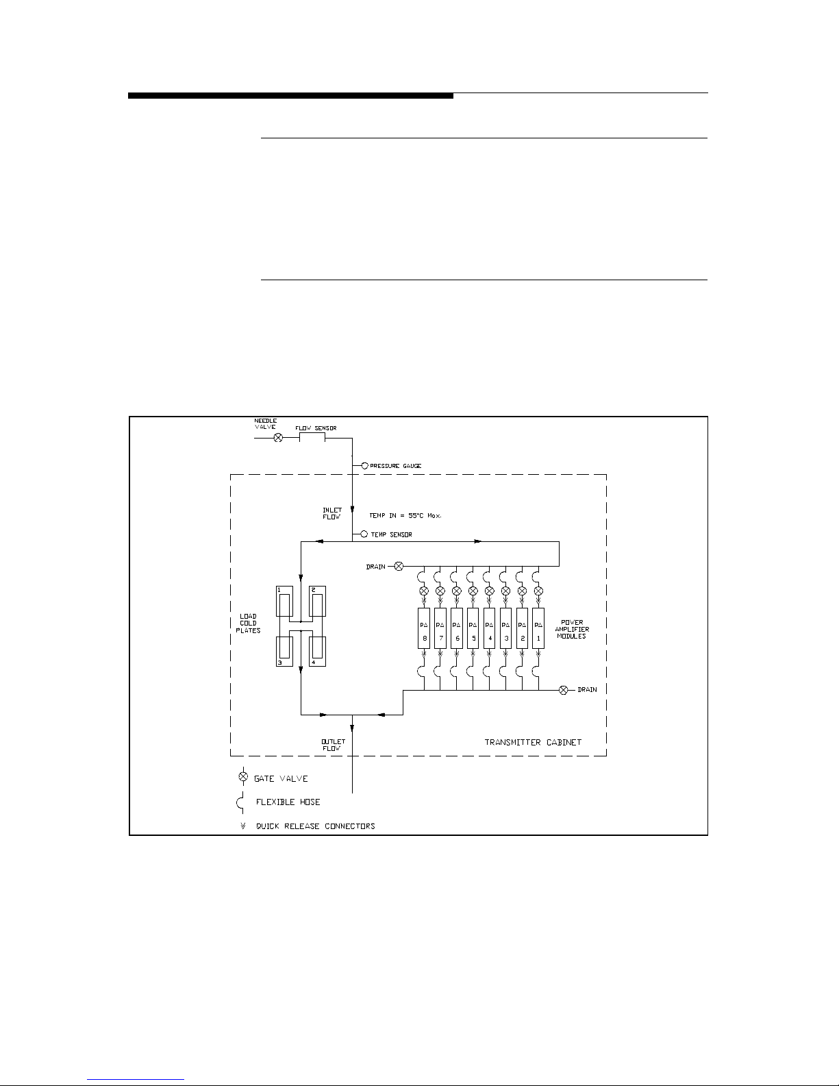
1.2.6.4 Transmitter Cold Plates
Each PA Module has an attached liquid cooled cold plate which connects to the
cooling system with flexible hoses and quick release connectors. There is also a
separate cold plate mounted inside the transmitter cabinet to which all of the
combiner reject loads are attached. See Figure 1-7.
Figure 1-7 Internal Transmitter Liquid Cooling System
Page 27

2/25/03 888-2473-001 1-13
WARNING: Disconnect primary power prior to servicing.
Section 1 Introduction
ATLAS Series™
1.2.7 V-XCAST™ Exciter
The ITIS V-XCAST™ COFDM (Coded Orthogonal Frequency Division Multiplex)
exciter is used with the Atlas Series™ transmitter. This exciter is described in a
separate instruction book. A second hot standby exciter/driver and drive chain
switcher is available as an option. The exciter is controlled and configured using an
RS-232 serial connection. Software is provided with the exciter. A serial diagnostic
and monitoring port is also provided.
The COFDM exciter V-XCAST is a fully compliant DVB-T (Digital Video
Broadcast - Terrestrial) exciter and up-converter supporting both 2K and 8K
operations, specifically designed for commercial networks. This device performs
channel coding and OFDM modulation of a MPEG2 transport stream. One single
unit drives the Atlas Series™ transmitter with a fully modulated RF DVB-T
channel. The excellent quality and stability of analogue UHF signal output
maximises the TV transmitter efficiency, decreasing global cost. Thanks to its ASI
(Asynchronous Serial Interface) standardised interface, the V-XCAST exciter can
be used with any DVB compliant source equipment.
A flexible Bit Rate Adaptation mechanism, with PCR (Program Clock Reference)
restamping, is provided, giving an independence between the multiplexer rate and
the DVB-T rate.
Test generators are included, which allow easier BER (Bit Error Rate) measurement
with the optional V-TER, professional test receiver.
The V-XCAST COFDM exciter accepts a SFN (Single Frequency Network) option
which allows to set up single frequency networks with use of a SFN adapter at the
DVB multiplexer site. In SFN mode, the COFDM modulation and RF up-converter
are locked on a stable 10 MHz external reference coming from GPS (Global
Positioning System). With the optional internal GPS receiver, the V-XCAST offers
a compact and reliable SFN modulation solution.
The full device remote control can be performed via the MIP channel (remote
control from network head-end), or via an RS232 port and the PC software (local
control or remote control via modem) or via a standard SNMP (Simple Network
Management Protocol) manager, allowing a very fast integration with most Control
Systems.
The same PC software can be used for easy logging and maintenance, thanks to an
accessible rear panel RS-232 connector. It will be used to adjust digital
precorrection curves.
Alarms are monitored on front panel leds and on a rear side connector as relay
contacts. Alarms are optionally controlled and monitored by standard SNMP
managers.
Page 28

1-14 888-2473-001 2/25/03
WARNING: Disconnect primary power prior to servicing.
Section 1 Introduction ATLAS Series™
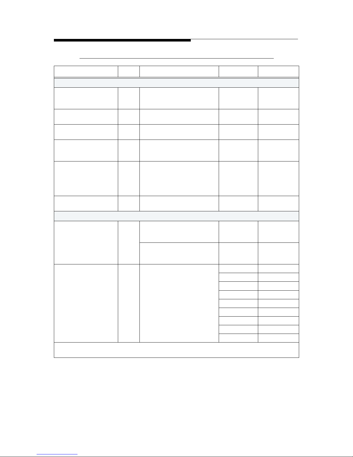
1.3 General Specifications
The following table lists the specifications the Atlas Series™ UHF transmitter.
NOTE:
Specifications subject to change without notice.
Table 1-2 Atlas Performance Specifications
Item Units Conditions Notes Value
General
Frequency Range Mhz Any UHF TV
Channel
470-860
DTV Channel
Bandwidth
Mhz "8, 7 or 6
Mhz"
Cabinet Output Power
(before mask filter)
kW At 37 dB shoulders (measured
+/-4.2 MHz from center of
channel for a 8 Mhz DTV
channel)
Model Power
DVL400 450W
DVL800 850W
DVL1100 1.25kW
DVL1500 1.7kW
DVL2200 2.5kW
DVL3000 3.4kW
DVL4300 4.7kW
DVL5700 6.2kW
System Output Power
(after mask filter)
kW At 37 dB shoulders (measured
+/-4.2 MHz from center of
channel for a 8 Mhz DTV
channel)
Model Power
DVL400 410W
DVL800 800W
DVL1100 1.1kW
DVL1500 1.5kW
DVL2200 2.2kW
DVL3000 3.0kW
DVL4300 4.3kW
DVL5700 5.7kW
Variation in Output
Power
% At rated Power (RMS) within
AC mains variation spec and
+/- 5 Degree C from Nominal
Operating Temperature
+/-2
RF Load Impedance Ohms 50
RF Load VSWR Measured on any 8 Mhz
channel
1.1:1
Output Connector
Medium Power
"1-5/8"" EIA
Flanged"
Output Connector High
Power
"3-1/8"" EIA
Flanged"
Page 29
2/25/03 888-2473-001 1-15
WARNING: Disconnect primary power prior to servicing.
Section 1 Introduction
ATLAS Series™
Performance
Equivalent Noise
Degradation (END)
dB Measured per ETR 290 < 0.5
Modulation Error Ratio
(MER)
dB At rated Power and -37 dB
shoulders (using HP89440)
Within the
performance
temp window
> 33 dB
Phase Noise dBc/HzAfter warm up time -95@10Khz
Frequency stability
(without external
reference)
+/- HzStand alone transmitter < 17
Frequency stability
(with external
reference)
+/- HzRequires external 10 Mhz < 0.1
Coarse Frequency
Offset Range
+/Mhz
In steps of 166 KHz 4
Fine Frequency Offset
Range
+/KHz
In steps of 1Hz 166
Transmitter Processing
Delay
msec From TS input to RF output Used in SFN
operation
programmabl
e to 1 sec max
Spurious Radiation
Harmonics and
spurious emissions
dBc "After Mask Filter,
referenced to average
transmitter power"
Depends on
DTV Mask
requirement
of individual
countries
< -60
Harmonics before
Mask Filter
dBc Transmitter output before
mask filter
< -40
AC Line
AC Line Voltage (3phase models)
VAC 3-phase 50/60 Hz select one "380, 400,
415"
AC Line Voltage (1phase models)
VAC 1-phase 50/60 Hz "220,230,240
"
AC Line Voltage
Variation
% "+10, -15"
Power Factor (3-phase
models)
"DVL1500, DVL2200,
DVL3000, DVL4300,
DVL5700"
> 0.94
Power Factor (1-phase
models)
"DVL
400,DVL800,DVL1100"
> 0.97
Overall Efficiency
(typical)
% AC power to RF average
power
18% Typical
Table 1-2 Atlas Performance Specifications
Item Units Conditions Notes Value
Page 30
1-16 888-2473-001 2/25/03
WARNING: Disconnect primary power prior to servicing.
Section 1 Introduction ATLAS Series™
Environmental
Operational
Temperature Range
°C Derate 2
degree C per
300m AMSL
0-45
Operational Relative
Humidity
% non-condensing 0 - 90
Altitude metersAMSL 0-4000
Cooling Method
(primary)
% Liquid cooling Propylene
Glycol/
Water
50/50
Acoustic Noise dBA Measured 1m from front of
cabinet and 1m up from the
floor (does not include
cooling pump module and
heat exchanger)
<65
Residual Heat
transferred to room
kW Maximum per transmitter
cabinet with 8PAs
< 3.9
Physical
Dimensions mm Single Cabinet Transmitter DVL400 thru
DVL3000
700W x
1980H x
1040D
Dual Cabinet Transmitter DVL4300 &
DVL5700
1400W x
1980H x
1040D
Weight Kg Weight includes all options Model Weight
DVL400 303
DVL800 330
DVL1100 365
DVL1500 399
DVL2200 463
DVL3000 526
DVL4300 894
DVL5700 1020
"Note: Unless otherwise noted, these specifications apply at the output of a Harris supplied mask
filter."
Table 1-2 Atlas Performance Specifications
Item Units Conditions Notes Value
Page 31

2/25/03 888-2473-001 2-1
WARNING: Disconnect primary power prior to servicing.
ATLAS Series™
Section 2
Installation /
Initial Turn-On
2
2.1 Introduction
This section includes the information necessary for installation and initial turn on of
an Atlas Series DVB-T, solid state, UHF transmitter. Information is included for
single and multiple cabinet configurations. Due to the modular nature of the Atlas,
all models have the same basic cabinet level installation and testing procedures,
with additional information given for multiple cabinet connections and testing.
2.2 Documentation
The following is a list of documentation that ships with the transmitter (in addition
to this manual):
a. Drawing Package with a complete set of prints for the transmitter. This
should have your transmitter model number printed on the front.
b. CD-ROM - There should be a CD-ROM accompanying this manual. It
contains:
1. An Acrobat (pdf) version of this manual. This is convenient as it allows
full search capability, color pictures and allows extra copies to be made
at any time.
2. An Acrobat (pdf) version of the Drawing Package with a linked index
for quick access. This also allows printing of extra copies or
replacements.
3. A copy of the transmitter control software of the same revision as
loaded into the transmitter at the factory.
4. Harris ISP (In-System Programming) software which is used to install
software upgrades into the transmitter controllers.
Page 32

2-2 888-2473-001 2/25/03
WARNING: Disconnect primary power prior to servicing.
Section 2 Installation / Initial Turn-On ATLAS Series™
2.2.1 Installation Drawings
It is recommended that you look through the drawing package to familiarize
yourself with the information available. Although drawings are provided for all
assemblies in the transmitter, most of the installation and planning information is
given in the following drawings (in the supplied drawing package):
a. Transmitter Outline Drawing - 843-5550-136 (843-5550-173 for DVL 4300
and 5700) Shows connections points for AC, control, coolant lines and rf output. Also gives cabinet dimensions, required cabinet clearances and a table of
basic requirements for all models.
b. AC Power Flow Diagram - Shows overall ac wiring and has information on
proper wire, fuse and breaker sizes as well as location of disconnects.
1. 843-5550-188 (sht 1) - DVL400 - DVL1100, 220/240Vac single phase
2. 843-5550-188 (sht 2) - DVL1500 - DVL3000, 380 - 415Vac 3 phase.
3. 843-5550-217 for DVL 4300 and 5700
c. RF Equipment Layout - Shows one possible placement of the transmitter RF
components based on minimum required clearances.
1. 843-5550-169, DVL400 - DVL2200 - Sheet 1 gives dimensions using
the Teracom filter while sheet 2 shows the Spinner filter.
2. 843-5550-171, DVL3000 - Sheet 1 gives dimensions using the
Teracom filter while sheet 2 shows the Spinner filter.
3. 843-5550-172 for DVL 4300 and 5700
d. Cooling System Layout - 843-5550-170 (843-5550-217 for DVL 4300 and
5700) Shows basic plumbing component locations and connections, flow rate
and pressure information as well as simplified cooling diagrams.
e. Electrical Installation Diagram - 843-5550-189 (843-5550-218 for DVL 4300
and 5700) Shows interconnect wiring between transmitter and all external
systems, including AC connections.
f. Cooling System Electrical Diagram - 843-5396-865 (3phase) and 843-5396-
880 (single phase) - Shows the internal workings of the Cooling Control
Panel and all interconnects with transmitter, pump module and heat
exchanger, including AC connections.
g. Transmitter Wiring Diagram - Interconnection wiring diagram for all
assemblies inside the transmitter cabinet. The wiring diagrams are model
dependent:
• 843-5550-102, DVL 400 up to DVL 1100 - Single Cabinet with 1 to 3 PA
Modules.
• 843-5550-154, DVL 1500, single cabinet with 4 PA modules
• 843-5550-004, DVL 2200 and DVL 3000 - Single Cabinet with 6 or 8 PA
Modules.
Page 33

2/25/03 888-2473-001 2-3
WARNING: Disconnect primary power prior to servicing.
Section 2 Installation / Initial Turn-On
ATLAS Series™
• 843-5550-100, DVL 4300 and DVL 5700 - Additional PA Cabinet
Wiring Diagram. Only used with dual cabinet transmitters, this
schematic is used in addition to the 843-5550-004.
h. Pump Module Outline Drawing - 843-5550-175
i. Heat Exchanger Outline Drawing- 843-5550-176
2.3 Installation Checkboxes
Located to the left of each important step in the installation procedure is a checkbox
like the one to the left of this paragraph. As each step in the procedure is completed,
the box should be checked. This provides a quick confidence check at the end of the
procedure that no steps were skipped. The primary goal of each step is also in
bold letters, with the rest of the paragraph being support information toward that
goal.
NOTE:
In case of discrepancy between the connections listed in the schematics versus the information given in this installation section, the wiring information in
the schematics should be considered the most accurate. All connections listed
in this section should be verified with the schematics before initial turn on.
2.4 Transmitter Cabinet Placement
The transmitter cabinet should be placed where it will have approximately 1 meter
clearance on each side and in the back. The front of the transmitter should have a
clearance of at least 1.5 meters to allow access for removal and installation of the
PA and power supply modules. There are several equipment layout drawings
included in the drawing package to help plan the cabinet placement:
• 843-5550-136 (843-5550-173 for DVL 4300 and 5700) Transmitter
Outline Drawing
• 843-5550-169 171 (843-5550-172 for DVL 4300 and 5700) Rf
Equipment Layouts
• 843-5550-170 (843-5550-213 for DVL 4300 and 5700) - Cooling System
Layout
Remove the bolts holding the transmitter to the wooden pallet and carefully
slide the cabinet off the pallet.
Remove the front door from each cabinet and set it aside in a safe place for the
rest of the installation process.
Use shims or flat washers to make sure the transmitter is level and solid (not
rocking). For 2 cabinet systems, PA Cabinet 2 (the one without the control panel)
Page 34

2-4 888-2473-001 2/25/03
WARNING: Disconnect primary power prior to servicing.
Section 2 Installation / Initial Turn-On ATLAS Series™
should be placed on the right side of Cabinet 1 (looking from the front of the
transmitter). There are holes in the sides of the cabinets which should line up to
allow for interconnect wiring between the cabinets. One hole is approximately in
the middle and the other near the bottom (rear) of the cabinets.
NOTE:
Do not install the PA modules or the power supplies at this time. These will
be installed just before the initial turn on procedure.
2.5 Cooling System Installation
The major components of the Atlas cooling system include the pump module,
cooling control panel and heat exchanger. The following procedure will rely heavily
on the following schematics.
DVL 400 - DVL 3000:
a. Electrical Installation Diagram - 843-5550-189.
b. AC Power Flow Diagram- 843-5550-188.
c. Cooling System Electrical Diagram- 843-5396-865.
d. Cooling System Layout - 843-5550-170.
DVL 4300 &DVL 5700:
a. Electrical Installation Diagram - 843-5550-218.
b. AC Power Flow Diagram - 843-5550-217.
c. Cooling System Electrical Diagram - 843-5396-865.
d. Cooling System Layout - 843-5550-213.
When planning the installation, keep the following restrictions in mind:
a. The pump module cannot be placed more than 8 meters away from the trans-
mitter cabinet.
b. The pump module must be less than 8 meters away from the heat exchanger.
c. The cooling control panel should also be mounted relatively close to the
pump module, and no more than 3 meters away.
d. It would also be a good idea to have the front of the cooling control panel
visible while standing in front of the transmitter (this is not a requirement).
!
WARNING:
DISABLE AND LOCK OUT STATION PRIMARY POWER BEFORE PRIMARY
POWER CABLES ARE CONNECTED TO THE EQUIPMENT.
Page 35

2/25/03 888-2473-001 2-5
WARNING: Disconnect primary power prior to servicing.
Section 2 Installation / Initial Turn-On
ATLAS Series™
Set the pump module in place and mount the cooling control panel. Use shims
or flat washers to make sure the pump module is level and solid (not rocking). The
cooling control panel should be mounted to a solid surface, or structure, able to
withstand the minor vibration of the contactors without coming loose.
Connect one conduit from the control panel to the pump module and one to the
heat exchanger for AC wiring. Depending on local wiring codes and personal
preference, another set of conduit runs may be installed for the control and status
wires to the pump module and the heat exchanger. The small signal wires and the
AC wiring should never be run in the same conduit.
Open the Isolator switches on the cooling control panel, pump module and heat
exchanger. This will allow them to be closed one at a time later to check for wiring
problems.
Connect the AC wiring between the cooling control panel and the pump
module and heat exchanger. Follow the AC Power Flow Diagrams and Electrical
Installation Diagrams mentioned at the beginning of this section. All AC
connections are connected to terminals labeled X1.
Connect the control and status wires between the cooling control panel and the
pump module with the supplied 16-2-12C (screened) multi-conductor cable.
These connections are on Electrical Installation Drawing, 843-5550-189 or 8435550-218. These low level signals connect from terminals X1-8 thru X1-15 in the
pump module to X2-21 thru X2-28 in the cooling control panel. Table 2-1 is a
connection reference chart.
Connect the control and status wires between the cooling control panel and the
heat exchanger with the supplied 16-2-12C (screened) multi-conductor cable.
These connections are on the Electrical Installation Drawing. These low level
Table 2-1 Pump Module Control and Status Connections
Cooling Control Panel Pump Module
X2-21 X1-8
X2-22 X1-9
X2-23 X1-10
X2-24 X1-11
X2-25 X1-12
X2-26 X1-13
X2-27 X1-14
X2-28 X1-15
These connections should be verified using Schematic
#843-5550-189 or 843-5550-218
Page 36

2-6 888-2473-001 2/25/03
WARNING: Disconnect primary power prior to servicing.
Section 2 Installation / Initial Turn-On ATLAS Series™
signals connect from terminals X1-8 thru X1-15 in the heat exchanger to X2-13 thru
X2-20 in the cooling control panel. Table 2-2 is a connection reference chart.
NOTE:
Condensation can occur in the conduit leading to the outside heat exchanger
from the control panel. This conduit should be caulked or sealed after the system is tested and operational.
Connect the control and status wires between the cooling control panel and the
transmitter with the supplied 16-2-12C (screened) multi-conductor cable.
These low level signals connect from terminals X2-1 thru X2-12 in the cooling
control panel to J12-1 thru J12-12 on the External I/O board in the transmitter (pin
for pin connection).
Connect the test load flow switch to J18-9 and J18-10 on the External I/O
board in the transmitter. This will mute the transmitter rf output if there is no
coolant flow through the test load (provided the U-Link is in position 2, transmitter
to test load). Specified wire is 7-2-4C, 4 conductor cable. A closed contact is
required to operate the transmitter. Some switches may also use +15V and ground.
The connections are as follows:
• J18-9 to flow switch terminal 1 (common)
• J18-10 to flow switch terminal 3 (N.O.)
Depending on the switch the following may also be required:
• J11-1 (+15Vdc) to flow switch terminal 2 (+DC)
• J11-6 (ground) to flow switch terminal 4 (-DC)
Table 2-2 Heat Exchanger Control and Status Connections
Cooling Control Panel Heat Exchanger
X2-13 X1-8
X2-14 X1-9
X2-15 X1-10
X2-16 X1-11
X2-17 (2 conductors) X1-13 (2 conductors)
X2-18 (2 conductors) X1-14 (2 conductors)
X2-19 (2 conductors) X1-15 (2 conductors)
X2-20 X1-12(GND)
These connections should be verified using Schematic
#843-5550-189 or 843-5550-218
The Gray rows require
2 conductors be used
on each terminal for
current capacity.
NOTE:
Page 37

2/25/03 888-2473-001 2-7
WARNING: Disconnect primary power prior to servicing.
Section 2 Installation / Initial Turn-On
ATLAS Series™
If there is a temperature overload switch on the test load, (as would be the case
for an air cooled load) it should be connected to J18-11 and J18-12. This will
mute the transmitter rf output if the test load temperature threshold is exceeded. A
closed contact is required to operate the transmitter. A jumper is installed at the
factory which must be removed to use this input.
For the DVL 4300 and DVL 5700only, connect the cabinet combiner reject
load coolant flow switch. The DVL 4300 and DVL 5700 use a liquid cooled reject
load for the cabinet combiner. The flow switch connection, as shown on drawing
#843-5550-218, will mute the transmitter rf output if there is no coolant flow
through the reject load. Specified wire is 7-2-4C, 4 conductor cable. A closed
contact is required to operate the transmitter. Some switches may also use +15V and
ground. The connections are as follows:
• J18-11 to flow switch terminal 1 (common)
• J18-12 to flow switch terminal 3 (N.O.)
Depending on the switch the following may also be required:
• J11-1 (+15Vdc) to flow switch terminal 2 (+DC)
• J11-6 (ground) to flow switch terminal 4 (-DC)
2.6 Transmitter AC Connection
For Conduit connections to the transmitter refer to Figure 2-1 or the Transmitter
Outline Drawing 843-5550-136 (or 843-5550-173 for DVL 4300 & DVL 5700),
Top View.
!
WARNING:
DISABLE AND LOCK OUT STATION PRIMARY POWER BEFORE PRIMARY
POWER CABLES ARE CONNECTED TO THE EQUIPMENT.
NOTE:
The 3 phase version of the Atlas transmitter uses a stepdown transformer for
all single phase loads in the transmitter, therefore no neutral connection is
required in the cabinet. DO NOT run a neutral connection to the transmit-
ter as there is no connection point and the neutral should not be connected to the cabinet ground. A safety ground wire is required and connects
to E10 which is shown in Figure 2-2 on page 2-9.
Page 38

2-8 888-2473-001 2/25/03
WARNING: Disconnect primary power prior to servicing.
Section 2 Installation / Initial Turn-On ATLAS Series™
The DVL1500 -DVL5700 models are 3 phase 380/400/415Vac at 50/60Hz delta or
wye. The DVL400 - DVL1100 models are equipped for single phase 220/240Vac at
50/60Hz. If voltage variations in excess of +10/-15% are anticipated, the transmitter
power input must be equipped with automatic voltage regulators (optional
equipment) capable of correcting the mains voltage.
NOTE:
It is important that the correct voltage be specified as the MOV protection
components are different for delta, wye or single phase configurations.
Connect the Primary AC conduit to the top of the transmitter cabinet.
The top of the transmitter cabinet has pre-cut holes for conduit connections as
shown in the outline drawing. The AC input is routed down through the hollow
space on the left side of the transmitter cabinet and out through a hole near the base
of the cabinet and up to the front of the cabinet behind the breaker panel.
Figure 2-1 Conduit Connections and AC Wiring
Connect the AC wires to the primary AC disconnect switch S3.
For 3 phase or single phase, the AC input wires will connect to the AC disconnect
switch S3, located on the front of the transmitter in the lower left-hand corner. It
will be necessary to unscrew the breaker panel to make the connection to AC
disconnect switch S3 as shown in Figure 2-2.
Connect the safety ground wire to terminal E10, shown in Figure 2-2. Replace
the breaker panel when finished.
Coolant Supply
Coolant Return
Ext I/O
AC IN
1 5/8 EIA RF Output
Exhaust
Air
Page 39

2/25/03 888-2473-001 2-9
WARNING: Disconnect primary power prior to servicing.
Section 2 Installation / Initial Turn-On
ATLAS Series™
Figure 2-2 AC Connection to AC Disconnect Switch, S3
Verify that the Primary AC line voltage is correct for the installed MOV
board. Measure the primary AC line voltage from phase to phase and write it in the
blank below. The transmitter was setup in the factory with a 380/400/415Vac Delta
or WYE 3 phase, or 220/240Vac single phase configured MOV board. Make sure
that the transmitter is setup for the same power configuration used at the site by
checking the factory test data sheet.
VAC
NOTE:
There must be less than a 5% imbalance between the phases to allow the
transmitter to operate.
Verify that the single phase step-down transformer is tapped correctly. This
step is not required on single phase transmitters. Step-down transformer T1
reduces the 380/400/415Vac down to 220Vac for the transmitter low voltage power
supplies, fans and exciters. Using the voltage measured above, check the primary
tapping of T1. TB4 is used to re-tap the transformer if necessary, by moving wire
#58. Figure 2-3 shows a chart of the 3 possible tap positions. The transformer is
located in the bottom rear section of the PA cabinet.
Figure 2-3 Tapping Stepdown Transformer, T1, using TB4
Safety Ground Connection
E10
Primary Line
Voltage
380Vac
400Vac
415Vac
Wire #58 TAP
on TB4
Terminal 5
Terminal 4
Terminal 3
Also shown on
843-5550-004
Wiring Diagram
Page 40

2-10 888-2473-001 2/25/03
WARNING: Disconnect primary power prior to servicing.
Section 2 Installation / Initial Turn-On ATLAS Series™
2.7 Second PA Cabinet Interconnections
NOTE:
The following only applies to the DVL 4300 and the DVL 5700 transmitters
which have an additional PA Cabinet (Cabinet 2).
The following interconnects will have to be made between from the Main PA/
Control cabinet (called Cabinet 1) to the Additional PA Cabinet (called Cabinet 2).
This information is found on schematics 843-5550-004 and 843-5550-100. The
following cables are labeled and already have one end connected to Cabinet 1 where
they were bundled for shipping. The cables should be routed through the
appropriate hole between the cabinets for connection to Cabinet 2.
Connect the 220VAC from the stepdown transformer in Cabinet 1, to TB2 in
Cabinet 2 for the low voltage supplies. The connections are as follows:
• Wire W61 connects from TB2 terminal #3 in Cabinet 1 to TB2 terminal #1 in
Cabinet 2.
• Wire W62 connects from TB2 terminal #6 in Cabinet 1 to TB2 terminal #4 in
Cabinet 2.
Connect the 3 phase ac wiring from TB1 in Cabinet 1 to TB1 in Cabinet 2. The
connections are as follows:
• Wire #21 connects from TB1-3 in Cabinet 1 to TB1-3 in Cabinet 2.
• Wire #22 connects from TB1-7 in Cabinet 1 to TB1-8 in Cabinet 2.
• Wire #23 connects from TB1-11 in Cabinet 1 to TB1-13 in Cabinet 2.
Route the ground strap between the 2 cabinets and secure under the brass
blocks provided.
Connect coaxial cable W57 from DCU connector J8 in Cabinet 1, to J1 on the
Backplane Interface board in Cabinet 2.
Connect the Control Bus (ribbon cable) W56 from Backplane Interface J17 in
Cabinet 1 to the Backplane Interface J17 in Cabinet 2. This connects the CAN
bus and parallel control lines to the PA Modules, RF Monitor and PS Monitor
boards.
Page 41

2/25/03 888-2473-001 2-11
WARNING: Disconnect primary power prior to servicing.
Section 2 Installation / Initial Turn-On
ATLAS Series™
2.8 Signal and Ground Connections
NOTE:
Control and signal wires should never be run in the same conduit with any
AC wiring. A separate conduit should be used for control and signal cables.
Connect an MPEG Transport Stream DVB ASI input to each exciter.
Depending on purchased options, each exciter also has inputs for a GPS Aerial, 1
PPS input, 10MHz Reference and Demodulator A. For more information refer to
the V-XCAST exciter manual.
Connect the sample cables from the Forward and
Reflected directional couplers at the system output
(after the filter). These samples connect to a small
Customer I/O panel, with 2 "N" style connectors,
mounted to the ceiling of the cabinet. J1 is for Total
Forward and J2 is for Total Reflected. If necessary, these
samples will be calibrated using the GUI after initial
turn-on. These cables are not supplied since the required
length is determined at each site. For 2 cabinet systems
see 2.10.1 RF Sample Connections.
Connect a ground strap from the transmitter cabinet
E7 to the station ground. There is a brass ground block
located in the center of the cabinet. Remove the block,
punch holes in the copper ground strap and then mount
the strap under the block. The copper strap must be at
least 5cm wide and 0.5mm thick.
2.9 External Interlock Connections
The transmitter has inputs for up to four external interlocks on the External I/O
Board. More may be used by placing 2 or more interlocks in series. The transmitter
is shipped from the factory with jumpers in the External Interlock positions which
will allow the transmitter to operate with no external interlock connections. The
electrical installation drawing (843-5550-189 or 843-5550-218) shows that
Interlock #1, J18-1 to J18-2, is used by the 3 Port U-Link Panel or possibly a
motorized switch. The other three are to be used at the customers discretion. The
External Interlock circuit requires a closed connection between all of the following
terminals on the External I/O Board to turn the transmitter on:
• J18 pins 1-2 (connected to 3 Port U-Link Panel or switch)
• J18 pins 3-4
• J18 pins 5-6
• J18 pins 7-8
Page 42

2-12 888-2473-001 2/25/03
WARNING: Disconnect primary power prior to servicing.
Section 2 Installation / Initial Turn-On ATLAS Series™
2.10 Cabinet Combiner Connections
(DVL 4300 and 5700 only)
Drawing #843-5550-172 shows one possible layout of the rf equipment for the high
power systems. This includes the connections and locations of the hybrid combiner,
reject load, filter and patch panel.
Each PA cabinet has a 1 5/8" rf output line which connects to the hybrid combiner.
The hybrid is marked for Cabinet1, Cabinet 2, Output and Reject Load connections.
NOTE:
It is very important that the cabinets be connected to the correct hybrid port.
If they are reversed then all of the power will end up in the reject load port. If
this happens, the drive cables (W57 and 73) at the output of the DCU should
be reversed as well.
Precision directional couplers for measuring forward and reflected power should be
installed both before the filter and at the system output for measuring and
calibrating power. If the precision couplers are supplied by Harris, they will come
with a coupling chart which can be used for calbration purposes.
2.10.1 RF Sample Connections
Connect the RF Sample from the cabinet combiner reject load to J17 of the RF
monitor board in Cabinet 1. The hybrid combiner reject load is a water cooled
load which should also have an rf sample port between it and the hybrid. This
sample coupler is labeled DC4 on the 843-5550-100 Additional Cabinet Wiring
Diagram. This sample is used for Cabinet Phasing. This cable is not included since
the required length is determined at each site.
Connect the System Forward and Reflected directional coupler to the
transmitter. These samples connect to a small Customer I/O panel, with 2 "N" style
connectors, mounted to the ceiling of the cabinet. J1 is for Total Forward and J2 is
for Total Reflected. If necessary, these samples will be calibrated using the GUI
after initial turn-on. These cables are not supplied since the required length is
determined at each site.
NOTE:
For 2 cabinet systems these samples can be taken at DC3 (directional coupler
3) which is after the cabinet combiner but before the filter or can be connected to the directional coupler after the filter. The choice of which sample
to use is to be decided by the customer or by site requirements.
Page 43

2/25/03 888-2473-001 2-13
WARNING: Disconnect primary power prior to servicing.
Section 2 Installation / Initial Turn-On
ATLAS Series™
2.11 3 Port U-Link Panel Connections
Refer to the Electrical Installation drawing 843-5550-189 or 843-5550-218 for the
following connections:
Connect X1-1 and X1-2 on the U-Link panel to J18-1 and J18-2 (respectively)
on the External I/O Board in the transmitter. This is the transmitter external
interlock input and will shut the transmitter off if the U-Link is removed during
operation. A closed contact between J18-1 and J18-2 is required for the transmitter
to operate. Specified wire is 16-2-2C (screened) 2 conductor cable.
!
CAUTION:
ALWAYS SHUT THE TRANSMITTER OFF BEFORE REMOVING THE U-LINK TO
PREVENT POSSIBLE DAMAGE TO THE CONTACTS.
Connect one jumper between X1-3 and X1-4 and another between X1-5 and
X1-6 on the patch panel. This places the U-Link microswitches in series with the
interlock line to the transmitter. These may already be installed. This will only
allow the transmitter to be turned on if the U-Link is installed.
Connect the U-Link status switches S1B and S2B to the RF switch status inputs
on J14 of the External I/O Board in the transmitter. This allows the GUI to
display the position of the U-link panel and will cause a transmitter mute if neither
of these connections are pulled low. Specified wire is 7-2-4C (screened) 4
conductor cable. These four connections include:
• X1-7 to J14-3
• X1-9 to J14-4
• X1-8 and X1-10 both connect to J14-6 (ground)
*Verify these connections with the Electrical Installation drawing 843-5550-189 or
843-5550-218.
NOTE:
If an RF switch is used in place of the 3 port patch panel then an additional connection of the RF_SW_SEL_OUT at J15-9 on the External I/O board will have
to be connected to the select input on the switch. This output is a TTL open collector, active low, momentary signal meant to cause a switch to the opposite
position. The rf switch should then latch in that position until pulsed again.
IMPORTANT: This note only applies to systems without a patch panel or rf switch.
If no patch panel or switch is to be installed in the transmitter RF output line, then a
jumper must be placed on the External I/O board from J14-3 (RF_SW_A_STAT) to J14-1
(ground).
Page 44

2-14 888-2473-001 2/25/03
WARNING: Disconnect primary power prior to servicing.
Section 2 Installation / Initial Turn-On ATLAS Series™
2.12 Install PA and PS Modules
Plug the power supply modules into the slots at the bottom of the cabinet. The
breakers on the front of each power supply should be set to OFF.
!
WARNING:
THE PA MODULES ARE LARGE AND RELATIVELY HEAVY AT SLIGHTLY LESS
THAN 21KG. CARE SHOULD BE TAKEN TO AVOID PERSONAL INJURY AND/OR
DAMAGE TO THE MODULES.
Install the PA modules into the front of the
transmitter cabinet. Be sure to rotate the module
fasteners fully CCW before inserting. The hose
connections should be near the bottom. Rotate the
front fasteners CW to lock the module in place.
NOTE:
The PA Modules should be placed into the same slot in which they were
tested at the factory. Each module has a serial number tag. This serial number
is recorded on the factory test data sheet along with the appropriate slot number. Placing the module in a different slot will not cause any harm to the
transmitter but will require more time for module phasing.
Connect the Coolant hoses to the rear of the PA
Modules. Green hoses on the bottom and blue hoses
on the top. Push the hose coupling on to the module
nipple until it locks into place. Make sure the coolant
valves on the couplers are in the open position as
shown here. Turning the valve at a right angle to the
hose shuts off flow to the module.
!
CAUTION:
FAILURE TO CONNECT THE COOLANT HOSES TO THE MODULE COULD
RESULT IN A POSSIBLE MODULE FAILURE SHOULD POWER BE APPLIED.
!
WARNING:
THE ATLAS PA MODULES ARE DESIGNED TO HANDLE VERY HIGH TEMPERATURES AND MAY BE EXTREMELY HOT, UP TO 90O F (50O C) ABOVE ROOM
TEMPERATURE. DO NOT TOUCH THE MODULES WITH BARE HANDS AFTER
THE TRANSMITTER HAS BEEN RUNNING. SPECIAL GLOVES HAVE BEEN PROVIDED IN THE REAR OF THE CABINET OR CAN BE OBTAINED FROM HARRIS,
PART #0990006483 OR GRAINGER ITEM #4JF36.
Open all coolant system gate valves and make sure all drain valves are closed
before proceeding with the initial turn on.
Module
Fastener
Coolant
Valve
Page 45

2/25/03 888-2473-001 2-15
WARNING: Disconnect primary power prior to servicing.
Section 2 Installation / Initial Turn-On
ATLAS Series™
2.13 Initial Turn-On
Read and understand the entire initial turn-on procedure before starting. Detailed
use of all GUI screens is given in Section 3 Operation.
Shut off all of the front panel breakers.
Apply 3 phase primary power to the transmitter. Be ready to quickly disconnect
the power if necessary.
Engage the primary AC disconnect switch, S3 on the front breaker panel of the
transmitter cabinet.
Turn on the Control circuit breaker, CB1 and turn on the ac mains switch on
the rear of the exciter(s). This should apply power to the exciter(s). If the optional
exciter UPS (Un-interruptible Power Supply) is installed it should be active at this
time. Some UPS units have an on/off switch which must be pressed.
Turn on the fan circuit breaker, CB4. This will start the cabinet flushing fans in
the back door. If the fans do not start, disconnect the primary power and check the
ac wiring, including the T1 tap on TB4.
Turn on the LVPS1 and optional LVPS2 (Low Voltage Power Supply) circuit
breakers, CB2 and CB3. This will activate LVPS1 and optional LVPS2 and power
up the transmitter control system. The GUI display should show the Home (default)
screen shown in Figure 2-4. Try using the touchscreen buttons on the right side of
the GUI display (not the hardware buttons to the right of the GUI). If they do not
seem to be working or only work when pressed outside the button graphic, then go
to "5.7 Touch Screen Calibration" on page 5-11 before continuing. If the buttons
are working then proceed on to the next step.
Figure 2-4 Home Page
Page 46

2-16 888-2473-001 2/25/03
WARNING: Disconnect primary power prior to servicing.
Section 2 Installation / Initial Turn-On ATLAS Series™
Check the Low Voltage power supplies and AC Mains voltage. Press the
POWER SUPPLY button then PS METERS to access the PS metering screen.
Check for +15, -15 and +7.5 volts on LV PSU 1 and optional LV PSU 2, with the
BUS voltage slightly lower. The AC Mains should read close to your measured ac
voltage. Press BACK to return to the Power Supply screen.
Figure 2-5 Power Supply Metering
NOTE:
The PA PS readings should be zero and will be
shown as OFF on the main Power Supply screen.
They are only active after the transmitter ON button
is pressed. Do not press the transmitter ON button at
this time.
Press the PS FAULTS button to check for power supply faults. There should be
NO red indications or faults present. If a fault is present, see Section 6, Diagnostics
for more information.This screen is shown in Figure 3-27 on page 3-24.
NOTE:
A common fault is a 3 phase sequence fault, indicating the 3 phases have
been connected in the wrong sequence. If this is present, remove all power
from the transmitter and switch any 2 wires on transmitter disconnect switch
S3 or at the wall disconnect.
Customise the transmitter System Setup. Press the SYSTEM button then enter
the default password - 1895. Then press SYSTEM SERVICE and SYSTEM
SETUP. The System Setup screen displays the settings for station name, model
number, nominal output power, etc. Touch the screen at each field to enter the data
pertinent to the site. Once all the correct information in this screen has been entered,
press the CONFIG button. This screen is shown in Figure 3-38 on page 3-33.
PA PS: Readings
will be zero at
this time.
Any Power Supply
faults would cause
this icon to turn red
Page 47

2/25/03 888-2473-001 2-17
WARNING: Disconnect primary power prior to servicing.
Section 2 Installation / Initial Turn-On
ATLAS Series™
Check and set the transmitter configuration. Here, it is possible to set the
number of exciters, as well as the number of cooling pumps. Fully redundant
transmitters will have two exciters, two cooling pumps and two low voltage power
supply units (LV PSU). The second exciter, cooling pump and LV PSU are
optional. Press the BACK button to return to the System Setup screen.
NOTE:
The number of low voltage power supplies, number of PA power supplies
and 3-phase or single-phase operation is set via DIP switch, S1, located on the
PS Monitor Board. For more information see "Table 4-2 S1, Switch Settings,
PS Monitor Board" on page 4-33.
Set the Date, Time and LCD screen contrast. Press the CONTROL SET UP
button. Touch the screen at each field to enter the correct data for Date, time and
contrast. There is also a time entry for the LCD screen saver feature. For more
information on this screen see "3.9.4.1 System Setup" on page 3-33.
2.13.1 Cooling System Turn ON
The coolant recovery tank at the pump module must be filled to half capacity
with the recommended 50/50 glycol and water mixture.
NOTE:
If water is readily available at the site, it is recommended that the system is
filled with water, tested for leaks and then drained before filling with the
required 50/50 glycol/water mixture.
Preset the output valve at the pump module outlet for a reading of 68.
Turn ON the AC mains switch on the Cooling Control Panel. This will supply
AC power to the Pump Module and the Heat Exchanger.
Press the Remote button on the Cooling Control Panel (green LED should
illuminate). There are two modes of operation of the cooling pumps: Local and
Remote. The selection is made on the Cooling Control Panel. In the Remote mode,
the pumps will not start until they are commanded to do so by the transmitter. This
is the normal operating mode.
Turn ON the AC mains (Isolator) switches at the Pump Module. Depending on
the option ordered there will be one or two pumps (main and standby).
Turn ON the AC mains (Isolator) switches at the Heat Exchanger.
With the PA power supply breakers (on the front of the PS Modules) still OFF
and all quick connect hoses properly connected to each PA module, press the
transmitter ON button. The pump module should turn ON and start coolant flow
through the transmitter.
Page 48

2-18 888-2473-001 2/25/03
WARNING: Disconnect primary power prior to servicing.
Section 2 Installation / Initial Turn-On ATLAS Series™
Check immediately for any leaks at any of the cooling system points
• Transmitter inlet and outlet pipe connections
• Pump module inlet and outlet pipe connections
• Heat exchanger inlet and outlet pipe connections
• Test Load inlet and outlet pipe connections
• Test Load Flow Switch inlet and outlet pipe connections
NOTE:
Check pumps for correct direction of rotation. The pump casing is marked
with an arrow indicating correct direction of rotation. If rotation is incorrect,
interchange any two of the three phase input wires and recheck the orientation.
NOTE:
The fans on the cooling coils of the Heat Exchanger should blow upwards. If
a fan motor is rotating in the wrong direction, interchange any two of the
three phases and recheck the orientation.
!
WARNING:
DISCONNECT THE PRIMARY POWER AT SOURCE BEFORE INTERCHANGING
WIRES.
Check the Cooling Control Panel status lights. Depending on the coolant level in
the tank, there are indicators for Coolant Low and Coolant Fault. These yellow and
red LEDs should not be lit. If they are, there is insufficient coolant in the system.
Add coolant to the tank until no alarms are shown on the cooling control panel.
2.13.1.1 Setting the Transmitter Flow Rate
Check the transmitter flow rate. Press SYSTEM, SYSTEM COOLING and
COOLING METERS. The first line shows the transmitter flow rate.
Adjust the Flow Rate if necessary. Adjust the output valve at the pump module
until the flow rate indicated in the GUI matches the nominal flow rate of the
transmitter model as indicated in drawing 843-5550-170 (or 843-5550-213 for DVL
4300 and DVL 5700).
NOTE:
For 3 phase models, if the pump is unable to deliver the required flow rate,
check for correct wiring of the 3 AC phases. Incorrect wiring of the 3-phase
sequence would cause the pumps to operate but with much degraded perfor-
Page 49

2/25/03 888-2473-001 2-19
WARNING: Disconnect primary power prior to servicing.
Section 2 Installation / Initial Turn-On
ATLAS Series™
mance. Power down and rewire for correct sequence of the AC phases if
required.
2.13.1.2 Setting the Test Load Flow Switch Trip Level
To set the trip level, an external flow meter needs to be attached in series with the
load coolant supply.
Adjust the load coolant supply valve until the meter reads the correct flow
indicated in the table in drawing 843-5550-170 (843-5550-213 for DVL 4300
and DVL 5700).
!
CAUTION:
IN ORDER TO PROTECT THE TEST LOAD, THE LOAD FLOW SWITCH SHOULD
BE SET TO OPEN IF ADEQUATE FLOW IS NOT PROVIDED TO THE LOAD.
Check the Load interlock. Once the flow rate is correct, press OUPUT to go to the
RF Output screen. This screen displays status of the load interlock (open or closed).
Adjust the flow switch trip level until the GUI displays Load Interlock: Closed.
Verify that the flow switch operates correctly by decreasing the amount of flow
through the load. The interlock should OPEN.
Go back to the nominal flow rate recommended for the test load. The interlock
should close.
2.13.1.3 Setting the Heat Exchanger Fan Turn ON Temperatures
The two stage thermostat that controls the heat exchanger fan turn on temperatures
were factory set for 32o C and 38o C. The adjustment dial inside the thermostat,
marked in deg C, controls fan A and is set at 32o C, which will switch fan A on
when the coolant temperature reaches 32o C. The +/- adjustment knob, next to the
dial, controls the differential when fan B will switch on, which is factory set to
+6o C. This will switch fan B on when the coolant temperature reaches 38o C.
2.13.1.4 Verifying Pump Switching
In modules with dual pumps, verify that both pumps operate properly by
switching pumps back and forth from the GUI screen. Also verify that correct
flow rate is achieved with either pump active.
Page 50

2-20 888-2473-001 2/25/03
WARNING: Disconnect primary power prior to servicing.
Section 2 Installation / Initial Turn-On ATLAS Series™
• Press SYSTEM then SYSTEM COOLING. This screen is shown in
Figure 3-32 on page 3-28.
• Select manual pump switching. Button should display MANUAL
ENABLED.
• Press pump select button for PUMP A ON then PUMP B ON. The pumps
should switch. This is indicated in the transmitter GUI screen, as well as
in the Cooling Control Panel status LED indicators.
Page 51

2/25/03 888-2473-001 2-21
WARNING: Disconnect primary power prior to servicing.
Section 2 Installation / Initial Turn-On
ATLAS Series™
2.13.1.5 Local Pump Operation
In normal operation (Cooling Control Panel set for Remote), the transmitter
commands the pump selection. If there is a need for operating the pump module
independently from the transmitter, the Local button on the Cooling Control Panel
should be activated.
Press the Local button in the Cooling Control Panel (yellow LED will
illuminate). Verify that pump switching is possible in the local mode by pressing the
Local PUMP A and PUMP B buttons.
Go back to Remote operation.
2.13.2 Setting Exciter Parameters
Set transmitter to OFF.
Set the Exciter Configuration. Press DRIVE CHAIN, DRIVE SERVICE, and
EXCITER CONFIG. The Exciter Configuration screen is shown in Figure 2-6.
Touch the screen at each field to enter the data. If you do not have an ASI program
source yet, then set the ASI Input to one of the PSRB (Pseudo Random Bit Stream)
options. See the exciter manual for more information on these choices.
Figure 2-6 Exciter Configuration Screen
NOTE:
The V-XCAST software is required for initial setup of the transmitter. The
Exciter modulation parameters and the curves required for the precorrection
of Linear and Non-linear distortions can only be set up with the aid of the
V-XCAST Exciter Software. This software runs on any Windows PC. Refer
to the exciter manual.
Page 52

2-22 888-2473-001 2/25/03
WARNING: Disconnect primary power prior to servicing.
Section 2 Installation / Initial Turn-On ATLAS Series™
The exciter has two DB9 serial communication ports on the rear panel. The Atlas
transmitter uses the port labeled Atlas Main Controller. The other port, labeled
RS232 is used to connect to the external PC running the V-XCAST software. The
ports are referred to as DCE port for the PC communications link and DTE port for
the Atlas Main Controller communications link.
The communications screen page from the V-XCAST software should be as
shown in Figure 2-7. Once the COFDM modulation and ASI input parameters have
been set up with the V-XCAST software, it is possible to view the settings from the
transmitter GUI.
Press the MOD. STATUS button to view the current modulation settings.
Press the INPUT STATUS button to view the exciter ASI input settings.
Figure 2-7 V-XCAST Communications Settings
NOTE:
Make sure that the DTE port is set up for ASCII protocol. Otherwise, the
Atlas Main Controller will not communicate with the exciter.
Page 53

2/25/03 888-2473-001 2-23
WARNING: Disconnect primary power prior to servicing.
Section 2 Installation / Initial Turn-On
ATLAS Series™
2.13.3 RF Initial Turn ON
Shut the transmitter OFF. The transmitter should be initially powered into the test
load.
Check and Set the ALC (Automatic Level Control). Press POWER AMP, then
PA METERS. The ALC number that controls the power output level of the
transmitter is seen at the upper right corner. Press the transmitter Power up/down
buttons (arrow-shaped buttons) until the ALC number reads 80 (70 for a 2 cabinet
system).
Figure 2-8 PA Meters Screen
Switch ON the AC breakers on the front of the PA power supply modules.
Press the transmitter ON button.
Verify that the reflected power is under 10 watts. The PA Meters screen shows
the forward and reflected power for each PA Module. Press the BACK button.
All PAs should show a green (OK) status on the GUI (Power Amp screen).
Press POWER SUPPLY and verify that all PA power supplies show OK status
(green).
Press OUPUT then OUTPUT METERS. This page shows the forward and
reflected powers for the Cabinet and Total System power (This could be before or
after the filter in a 2 cabinet system - site dependant). The VSWR is also indicated.
NOTE:
For DVL 4300 and DVL 5700 skip the following steps and go directly to
2.13.4 Cabinet Phasing.
Page 54

2-24 888-2473-001 2/25/03
WARNING: Disconnect primary power prior to servicing.
Section 2 Installation / Initial Turn-On ATLAS Series™
For single cabinet systems (up to DVL 3000) slowly bring up the transmitter
power to the nominal value, as indicated by the bar graph. Monitor the cabinet
forward and reflected powers, as well as the VSWR reading. A large VSWR (above
1.1) is indicative of a bad RF connection to the test load.
Check PA Module Phasing. For Single Cabinet systems, check the PA Module
phasing. If any of the PA Module reject load sample levels are above 0030, proceed
to "5.4 PA Module Phasing" on page 5-5.
Verify that the transmitter meter readings are close to the factory test data
meter readings, mainly all of the current and voltage readings.
2.13.4 Cabinet Phasing
NOTE:
This section only applies to DVL 4300 and DVL 5700, 2 cabinet transmitters.
As long as the PA modules have been placed back into their factory tested postions,
neither cabinet should require any PA Module phasing. However, since the output
system will probably have changed on-site, phasing of the 2 cabinets will most
likely be required. At full nominal power output all of the detected rf sample
readings shown in Figure 2-9 should read below 0030 with the Gain button set to
LOW or below 0100 with the gain button set to HIGH. To access the PA Reject
Service screen press OUTPUT, OUTPUT SERVICE and then PA REJECT
SERVICE.
STEP 1 To adjust the cabinet phasing, slowly raise the
transmitter power until you reach the nominal
operating power or the cabinet combiner reject load
sample reading goes above 300, whichever comes
first.
STEP 2 Next, press the Cab1 or Cab2 button (it does not
matter which) and tap the Phase Adjust +/- buttons
to minimize the reading above the buttons.
Alternately adjust the phase of the 2 cabinets to
reduce the reject sample level below 0030.
STEP 3 If full output power was not reached in step 1, raise the transmitter
power to 100%. Repeat Step 2 if the cabinet combiner reject sample
gets above 0030.
STEP 4 If any of the PA Module reject readings are above 0030 proceed to
"5.4 PA Module Phasing" on page 5-5, and then readjust the cabinet
phasing if necessary.
Verify that the transmitter meter readings are close to the factory test data
meter readings, mainly all of the current and voltage readings.
Page 55

2/25/03 888-2473-001 2-25
WARNING: Disconnect primary power prior to servicing.
Section 2 Installation / Initial Turn-On
ATLAS Series™
Figure 2-9 Module and Cabinet Phasing screen
2.14 Parallel Remote Control Connections
External Parallel remote control units can interface at the External I/O Board in the
rear of the cabinet. J13 through J17 are for remote Control, Status and Analogue
readings. The connectors are organised as follows:
• J13 and J14 - Remote Transmitter Control Functions
• J15 and J16 - Remote Status Outputs
• J17 - Remote Analogue Metering Outputs
NOTE:
The forward slash ( / ) in front of a signal name means active low. The signal
/INPUT 1 for example is activated by momentarily bringing that input low.
Signal names without the forward slash are considered active high. This convention is used throughout the schematics.
Detected rf sample
level, 0000 - 1023
PA Module Phase
Control Voltage
0000 - 1023
GOAL: To get the
detected rf sample
level readings
below 0030 (with
Gain set to LOW)
Press one of these
buttons
Module Group
select buttons
Reject Loads
Page 56

2-26 888-2473-001 2/25/03
WARNING: Disconnect primary power prior to servicing.
Section 2 Installation / Initial Turn-On ATLAS Series™
2.14.1 Transmitter Control Functions, J13 and J14
All control inputs use opto-isolators for surge protection. The opto-isolators are
powered by an internal +5Vdc from an isolation protection circuit, U54.
All transmitter control functions (except Remote RF Mute) are momentary ground
switching and require the remote control equipment to sink at least 15mA to
activate the function. The Pinouts of J13 and J14 are listed in Table 2-3.
Table 2-3 J13 & J14, External I/O Board, Remote Control Connectors
Connector Schematic
Label
Function
J13-1 GND Ground
J13-2 /INPUT 1 REMOTE_ON
J13-3 /INPUT 2 REMOTE_OFF
J13-4 /INPUT 3 REMOTE_RAISE
J13-5 /INPUT 4 REMOTE LOWER
J13-6 GND Ground
J13-7 GND Ground
J13-8 /INPUT 5 * REMOTE_DRA/B_SEL - Remote Drive Chain A/B Select (Toggle)
J13-9 /INPUT 6 * REMOTE_ASI_1/2_SELECT - ASI Input 1/2 Toggle
J13-10 /INPUT 7 REMOTE_RF MUTE_ON- Transmitter RF output is muted as long
as this input is held low. (High = Un-mute)
J13-11 /INPUT 8 REMOTE_Pump A/B Select
J13-12 GND Ground
J14-1 GND Ground
J14-2 /INPUT 9 REMOTE_RF_SW A/B_SELECT
J14-3 /INPUT 10 RF_SW_A_STAT (from 3 port U-Link panel or motorised rf
switch, Antenna position status) Input held low while in antenna
position
J14-4 /INPUT 11 RF_SW_B_STAT (from 3 port U-Link panel or motorised rf
switch, Load Position status) Input held low while in test load
position
J14-5 /INPUT 12 SPARE
J14-6 GND Ground
J14-7 GND Ground
J14-8 /INPUT 13 SPARE
J14-9 /INPUT 14 SPARE
J14-10 /INPUT 15 SPARE
J14-11 /INPUT 16 SPARE
J14-12 GND Ground
Page 57

2/25/03 888-2473-001 2-27
WARNING: Disconnect primary power prior to servicing.
Section 2 Installation / Initial Turn-On
ATLAS Series™
* Requires optional equipment
2.15 Remote Status Outputs, J15 & J16
All of the remote status outputs are open collector and will sink 100mA at up to
+24Vdc to provide an indication status is active. The pull up supply voltage for the
status indications can be supplied via J15 & J16 or can be supplied by an external
voltage source. The status output connections are listed in Table 2-4.
Table 2-4 J15 & J16, External I/O Board, Remote Status Outputs
Connector Schematic Label Status Output
J16-1 GNDB Isolated Ground
J16-2 +5VDC_ISOLATED Output - install jumper to J16-11 to use internal supply for
status pull ups. Otherwise an external supply will have to
be connected to J16-11.
J16-3 /OUTPUT 1 Off/On Status
J16-4 /OUTPUT 2 Life Support Status
J16-5 /OUTPUT 3 RF Mute Status
J16-6 /OUTPUT 4 Ext. Intlk Status - External Interlock Status
J16-7 /OUTPUT 5 Drive Chain Fault Status
J16-8 /OUTPUT 6 Power Amp Fault Status
J16-9 /OUTPUT 7 Output Fault Status
J16-10 /OUTPUT 8 Power Supply Fault Status
J16-11 +VDC_EXT_SUPPLY Input For External Pull Up Supply Voltage
J16-12 GNDB Isolated Ground
J15-1 GNDB Isolated Ground
J15-2 +5VDC_ISOLATED Output - install jumper to J15-11 to use internal supply for
status pull ups. Otherwise an external supply will have to
be connected to J15-11.
J15-3 /OUTPUT 9 Control Fault Status
J15-4 /OUTPUT 10 Cooling Fault Status
J15-5 /OUTPUT 11 Summary Fault Status
J15-6 /OUTPUT 12 Drive Chain A/B Select Status
J15-7 /OUTPUT 13 Pump A/B Select Status
J15-8 /OUTPUT 14 RF Switch A/B Status
J15-9 /OUTPUT 15 RF_SW_SEL_OUT (to motorised rf switch)
Page 58

2-28 888-2473-001 2/25/03
WARNING: Disconnect primary power prior to servicing.
Section 2 Installation / Initial Turn-On ATLAS Series™
J15-10 /OUTPUT 16 ASI 1 / 2 SEL Status
J15-11 +VDC_EXT_SUPPLY Input For External Pull Up Supply Voltage
J15-12 GNDB Isolated Ground
Table 2-4 J15 & J16, External I/O Board, Remote Status Outputs
Connector Schematic Label Status Output
Page 59

2/25/03 888-2473-001 2-29
WARNING: Disconnect primary power prior to servicing.
Section 2 Installation / Initial Turn-On
ATLAS Series™
2.15.1 Remote Power Metering, J17
Each analogue metering output will provide 0 - 4.096Vdc output into a 400 ohm
load (where 3Vdc = Full Scale). The connections for J17 are listed in Table 2-5.
Table 2-5 J17, External I/O Board, Remote Power Metering
Connection Schematic Label Metered Parameter
J17-1 GND Ground
J17-2 VOUTA Total Forward Power (After Filter)
J17-3 VOUTB Total Reflected Power (After Filter)
J17-4 VOUTC Forward Power Cabinet #1 (Before Filter)
J17-5 VOUTD Reflected Power Cabinet #1 (Before Filter)
J17-6 GND Ground
J17-7 GND Ground
J17-8 VOUTE Forward Power Cabinet #2 (Or Spare)
J17-9 VOUTF Reflected Power Cabinet #2 (Or Spare)
J17-10 VOUTG Spare
J17-11 VOUTH Spare
J17-12 GND Ground
Page 60

2-30 888-2473-001 2/25/03
WARNING: Disconnect primary power prior to servicing.
Section 2 Installation / Initial Turn-On ATLAS Series™
Page 61

2/25/03 888-2473-001 3-1
WARNING: Disconnect primary power prior to servicing.
ATLAS Series™
Section 3
Operation
3
3.1 Introduction
This section gives detailed operational information for the Atlas™ Series SolidState UHF DVB-T transmitter. Information will pertain mostly to the operation and
navigation of the Graphical User interface (GUI) Touchscreen display.
NOTE:
Operation of the V-XCAST exciter is covered in a separate manual which
came with the transmitter.
3.2 Transmitter Control Panel
The front panel user interface is a 1/4 VGA, LCD touchscreen display. The
touchscreen display uses software buttons to monitor the transmitter. Hardware
buttons for the primary transmitter functions such as ON/OFF, RAISE/LOWER and
Remote Enable/Disable are provided on the overlay panel next to the display as
shown in Figure 3-1.
Figure 3-1 Transmitter Control Panel
Page 62

3-2 888-2473-001 2/25/03
WARNING: Disconnect primary power prior to servicing.
Section 3 Operation ATLAS Series™
NOTE:
A similar set of GUI screens is available via web browser with an ethernet
network connection and the optional network interface box.
3.2.1 Main Menu "Quick" Buttons
Just to the right of the touchscreen, there are 5
hardware buttons which are part of the front panel
overlay. Located next to each button is a Status
LED which illuminates green under normal, no
fault conditions. These buttons provide quick
access to each of the 5 main transmitter groups,
namely:
a. Drive Chain
b. Power Amp
c. Output
d. Power Supply
e. System
The Status LED next to the button will turn red if
there is a warning or fault condition in that section
of the transmitter. It will be green if the sub-system
is normal. This provides quick access to the
required and relevant diagnostics information,
without having to be familiar with a menu structure.
NOTE:
To differentiate these buttons from the ones which show up on the LCD display, these will be referred to as "Quick" buttons in the manual text.
3.3 Graphical User Interface (GUI)
The GUI ("Gooey") was designed to provide an intuitive interface into the
transmitter control system. Once you know what information is available, finding
the information you want is simply a matter of following the screens to the desired
section of the transmitter. Menu Trees of all available screens is given at the end of
this section, see "3.10 GUI Menu Structures" on page 3-37.
For the most part, all navigation through the GUI screens is done via the
touchscreen and softkeys (software buttons). The exceptions are the 5 hardware
buttons mentioned above. The touchscreen display is also divided into an active
display area, which will change with each screen, and the global areas which are
present on all screens.
SYSTEM
Page 63

2/25/03 888-2473-001 3-3
WARNING: Disconnect primary power prior to servicing.
Section 3 Operation
ATLAS Series™
3.3.1 Global Status and Navigation
The top 2 sections of the touchscreen display are considered global because they
show up on all screens. The top line gives the transmitter model number and the
station name and/or location which is entered by the customer in the configuration
screen with a maximum of 24 characters including spaces.
Figure 3-2 Global Touchscreen Display Sections
The second line of the display has operational and status information including:
a. ON, Standby, OFF or Fault OFF as well as status information.
b. Transmitter Forward power output reading in numerical format (for multiple
cabinet transmitters this would be a system power reading and not for a single
cabinet). It is important to note that this is the power output after the filter.
c. Transmitter Forward power output reading in a Bargraph format (for multiple
cabinet transmitters this would be a system power reading and not for a single
cabinet). The 100% mark is based on the nominal power level or TPO (Transmitter Power Output) entered into the configuration screen. The bargraph will
also turn yellow if the power level is more than 20% higher or lower than the
nominal 100% level.
d. Main Menu Symbols which are basically status for the 5 main transmitter sec-
tions. If illuminated red, that section of the transmitter has one or more faults.
These status indicators correspond to the 5 hardware buttons to the right of
the display.
This top bar in Figure 3-2 should be all green under normal (no fault) operating
conditions. A yellow or red symbol or status indication should be investigated by
the station engineer.
Station Name and/or Location
Transmitter Model Number
Operation and Fault
Status
Transmitter System
Power Output
Power Bargraph
Main Menu Symbols
with Color Status
100% Mark - Based on TPO
setting in Configuration Menu
Page 64

3-4 888-2473-001 2/25/03
WARNING: Disconnect primary power prior to servicing.
Section 3 Operation ATLAS Series™
3.4 GUI Home Page
The HOME screen shown in Figure 3-3 is the primary operator screen and the
default screen after boot up. The HOME screen contains the most important general
operator information such as:
a. System and Cabinet Forward and Reflected power
b. Drive chain selection and status
c. ASI input selection and status
d. Individual Power Amplifier (PA) Cabinet status
e. AC line voltage. For 3 phase models, this is an average of all 3 phases. To see
the individual 3 phase line voltages press the Power Supply button.
f. Transmitter Channel
Figure 3-3 Home Screen
It also has the global status and operation information at the top of the screen which
shows the transmitter status and if there are any faults present.
The HOME button is a software button located in the lower right-hand
corner of all 5 main menu screens for quick navigation to the HOME
screen in Figure 3-3. This screen can only be accessed using the
software buttons on the touchscreen (there is no hardware HOME button). The
quickest way to access the HOME screen is to press any of the 5 hardware buttons
to the right of the display as there is a HOME button on each of those main menu
screens.
To Figure 3-4 on page 3-6
To Figure 3-12 on page 3-13
To Figure 3-20 on page 3-18
To Figure 3-26 on page 3-23
To Figure 3-30 on page 3-26
Page 65

2/25/03 888-2473-001 3-5
WARNING: Disconnect primary power prior to servicing.
Section 3 Operation
ATLAS Series™
There are always five touchscreen navigation buttons on the right side of the
display. These are different on almost every screen and, with the exception of the
HOME screen, do not relate to the hardware buttons on the front panel just to the
right of the display. These can also act as status indicators and turn red if a fault
condition is detected.
For multiple cabinet transmitters, there is also a navigation button
(shown to the right) for the second PA cabinet to allow access to
information specific to that cabinet. Pressing either of these buttons
will take you to the Power Amp screen shown in Figure 3-12 on page
3-13 for the desired cabinet.
This button is also a metering and status indicator for each PA cabinet
as it shows forward power (before the filter) and will change from OK
to Fault, if a problem is detected in that cabinet as shown to the right.
NOTE:
To simplify the discussion of GUI navigation, the following will navigate and
describe all of the screens under each of the 5 main menu buttons located to
the right of the touchscreen display (and on the right side of the GUI Home
page).
Page 66

3-6 888-2473-001 2/25/03
WARNING: Disconnect primary power prior to servicing.
Section 3 Operation ATLAS Series™
3.5 Drive Chain Main Menu
If you press the Drive Chain button on the control
panel overlay, or the Drive Chain button on the
HOME screen, it will take you to the screen shown in
Figure 3-4. The Drive Chain Menu structure is
shown in Figure 3-44 on page 3-37.
Figure 3-4 Drive Chain Screen
The Drive Chain screen is basically an exciter control and monitoring screen. It has
a power reading for each exciter output and allows the operator to select AUTO or
MANUAL switching mode for the drive chain when the optional dual drive system
is installed. Specifically it includes:
a. The operational and on-air status of 1 or 2 exciters (the second exciter is
optional) as well as the status of the ASI input to each exciter.
NOTE:
The standard V-XCAST exciter comes with only 1 ASI input. A second ASI
input with switching capability is optional.
b. The DCU or Drive Control Unit status and power output to the PA modules.
The DCU is an exciter switcher and a directional coupler to monitor exciter
power. For multiple cabinet system, the DCU also contains a splitter to drive
the second cabinet.
c. A Dual Drive Chain Control box (located at the bottom of the screen). This
section will be grayed out for single exciter systems. For dual exciter systems
this box has 3 switches:
To Figure 3-5
To Figure 3-6
To Figure 3-7
To Figure 3-3
Page 67

2/25/03 888-2473-001 3-7
WARNING: Disconnect primary power prior to servicing.
Section 3 Operation
ATLAS Series™
1. Auto/Manual - This toggle button should always be in the Auto posi-
tion for normal operation. Placing it in Manual mode prevents an
autoswitch to the alternate drive chain or ASI input. In AUTO mode, if
the on-air drive chain drops below 50% of nominal power the controller
will automatically switch to the backup drive chain (if available). Also,
if the ASI input is lost it will automatically switch to the optional second ASI input. Manual mode could be used if an exciter or driver has
been removed for service or for any application where an automatic
switch to the alternate drive chain is not desired.
2. Drive Chain A/B - This is the manual drive chain switch. To use this
button, place the Auto/Manual button to Manual, then press this button
to change the on-air drive chain.
3. ASI 1/2 - This is the manual ASI stream select button. Pressing this
button will change to the optional second ASI input.
3.5.1 Drive Chain Faults
When the "Drive Faults" button in Figure 3-4 is pressed, it will bring up the screen
shown in Figure 3-5. This screen is basically a fault display for 1 or 2 exciters. For
more information on these faults and what to do if one should occur, refer to the VXCAST exciter manual.
Figure 3-5 Drive Chain Faults Screen
Page 68

3-8 888-2473-001 2/25/03
WARNING: Disconnect primary power prior to servicing.
Section 3 Operation ATLAS Series™
3.5.2 Drive Meters
When the "Drive Meters" button in Figure 3-4 is pressed, it will bring up the screen
shown in Figure 3-6. This screen monitors the exciter power as reported by the
exciter and via a directional coupler in the Drive Control Unit or DCU.
Figure 3-6 Drive Chain Meters Screen
3.5.3 Drive Service
When the "Drive Service" button in Figure 3-4 is pressed, it will bring up the screen
shown in Figure 3-7. Press the Exciter Setup button to access the Exciter Setup
screen shown in Figure 3-8 or the DCU Setup button to access the DCU Setup
screen in Figure 3-11.
Figure 3-7 Drive Service Screen
Exciter power as
reported to controller
by V-XCAST exciter
Power reading
from DCU
directional
coupler (before switch)
To Figure 3-8
To Figure 3-11
Page 69

2/25/03 888-2473-001 3-9
WARNING: Disconnect primary power prior to servicing.
Section 3 Operation
ATLAS Series™
3.5.3.1 Exciter Setup
The Exciter Setup screen in Figure 3-8 is accessed from the Exciter Setup button on
the Drive Service screen. This screen provides access to some of the primary exciter
configuration parameters without having to connect an external computer to the
exciter serial port.
NOTE:
All parameters changed in this screen will be applied to both exciters simultaneously in a dual exciter system.
Figure 3-8 Exciter Setup Screen
[Drive Chain / Drive Service / Exciter Setup]
To change an exciter parameter simply tap the text window that contains the
parameter you wish to change. This will bring up the appropriate Pop-up window
which can then be used to edit the parameter. Two examples of these pop-up
windows are shown in Figure 3-9. Once the change is made, press DONE to
implement the change or CANCEL to exit the pop-up window without making any
changes.
• Channel - will accept any number from 14 - 69
• Channel Bandwidth - 6, 7 or 8 MHz
• Coarse Offset - changes carrier frequency in +/-125kHz steps
• Fine Offset - adds or subtracts from Coarse Offset to get desired carrier
frequency
• Frequency - this is calculated from the channel number and the offsets
To Figure 3-10
To Figure 3-10
To Figure 3-7
NOTE:
Exciter Status
shows optional
second exciter.
Page 70

3-10 888-2473-001 2/25/03
WARNING: Disconnect primary power prior to servicing.
Section 3 Operation ATLAS Series™
• Amp Correction Table and Filter Compensation Table - this provides a
way for the transmitter control system to call up different correction and
compensation tables stored in the exciters. Once set, this would only
need to be changed if the transmitter frequency is changed or for an N+1
system where one transmitter is backing up 2 or more transmitters at
different frequencies. The exciters can store up to 15 tables. For more
information on these tables refer to the V-XCAST exciter manual.
NOTE:
Setup of the Amp Correction and Filter Compensation tables
must be done using the ITIS V-XCAST software running on
an external PC and connected directly to the exciters via a
serial connection.
• ASI Input - Can be used to select program inputs, ASI 1 (or optional ASI
2) or PRBS (Pseudo Random Bit Streams). Note that each exciter input
can be configured separately. See V-XCAST exciter manual for more
information.
Figure 3-9 Editing the Exciter Setup Screen
NOTE:
The exciter status on the right side of the screen for each exciter is active status being read from the exciters. If the exciter has been configured using an
external computer (via serial port and the V-XCAST software) the readings
for both exciters may not be the same or match the data in the text boxes.
However, a change to any parameter will affect both exciters.
Page 71

2/25/03 888-2473-001 3-11
WARNING: Disconnect primary power prior to servicing.
Section 3 Operation
ATLAS Series™
3.5.3.1.1 Modulation Status and Input Status
Pressing the Modulation Status or Input Status button on the Exciter Setup screen
will take you to one of the screens in Figure 3-10. These screens read the
modulation and input settings from the exciters(s), allowing the settings to be
checked without connecting directly to the exciters with an external serial
connection. To change the settings will require a serial connection to the exciter and
use of the V-XCAST software. For more information on these settings refer to the
exciter manual. Note that optional Exciter B is not installed in this configuration and
is shown grayed out.
Figure 3-10 Modulation Status and Input Status Screens
Page 72

3-12 888-2473-001 2/25/03
WARNING: Disconnect primary power prior to servicing.
Section 3 Operation ATLAS Series™
3.5.3.2 DCU Setup
The DCU has a directional coupler for each exciter to measure exciter power
external to the exciter. This power reading shows up on the Drive Meters screen in
Figure 3-6. This screen is used to calibrate the display readings. A digital power
meter is required to measure the DCU output. Then by pressing the CHANGE
button next to the reading to be calibrated, the + and - buttons can be used to change
the reading to that measured on the digital power meter. Once this is done press
SAVE to store the changes or CANCEL to ignore all changes made.
NOTE:
This procedure should only be done by qualified service personnel. For more
information on transmitter calibration refer to Section 5 Maintenance and
Alignments.
Figure 3-11 DCU Setup Screen
To Figure 3-7
Page 73

2/25/03 888-2473-001 3-13
WARNING: Disconnect primary power prior to servicing.
Section 3 Operation
ATLAS Series™
3.6 Power Amp Main Menu
If you press the Power Amp button on the control
panel overlay, or the Power Amp button on the
HOME screen, it will take you to the screen shown in
Figure 3-12. The Power Amp Menu structure is
shown in Figure 3-45 on page 3-38.
Figure 3-12 Power Amplifier Screen
This screen shows the Forward and Reflected power for a particular PA cabinet. For
multiple PA cabinet transmitters, there are PA cabinet select buttons at the bottom
of the screen. Each of the amplifier select buttons in the middle of the screen are for
navigation to Module Status screens which have detailed fault status information on
each module. These buttons are also status indicators with 3 different modes:
a. OK - The icon is green as shown here for modules 2-7.
b. Fault - The icon turns red as shown here for module 1.
c. Disconnected - When a module is unplugged its icon turns gray as shown here
for module 8.
To get detailed information on a particular PA Module, press the desired amplifier
button in the middle of the screen. Any of these buttons will take you to the PA
Faults screen shown in Figure 3-13.
To Figure 3-13
To Figure 3-15
To PA Faults screen, Figure 3-13
To Figure 3-17
To Figure 3-3
Page 74

3-14 888-2473-001 2/25/03
WARNING: Disconnect primary power prior to servicing.
Section 3 Operation ATLAS Series™
3.6.1 PA Faults
This screen is basically a list of all of the faults monitored in each PA Module.
• An active fault will be highlighted in RED
• A warning condition will be highlighted in YELLOW.
The PA Faults screen in Figure 3-13, shows that PA Module #1, in PA Cabinet #1
has no faults. The NEXT and PREVIOUS buttons are used to access fault
information on each module. Since all of the possible fault status will not fit on the
one screen, pressing MORE will take you to the screen in Figure 3-14.
NOTE:
For a detailed explanation of all PA Faults in Figure 3-13 and Figure 3-14,
refer to Section 6, Diagnostics.
Figure 3-13 PA Faults Screen (PA Module 1 Selected)
Figure 3-14 More PA Faults Screen
To Figure 3-14
Page 75

2/25/03 888-2473-001 3-15
WARNING: Disconnect primary power prior to servicing.
Section 3 Operation
ATLAS Series™
3.6.2 PA Meters
This screen is accessed by pressing the "PA Meters" button in Figure 3-12. This
screen gives detailed PA metering by PA Cabinet. For a single cabinet transmitter
the PA Cabinet 2 button will be disabled and grayed out.
A complete set of PA Meter readings is given in the Factory Test Data. The Factory
Test Data readings are taken at nameplate power unless otherwise specified by the
customer. A full set of readings should also have been taken when the transmitter
was installed if the nominal operating power does not match the factory tested
power level.
NOTE:
For more information on PA Meter Readings see Section 6, Diagnostics.
Figure 3-15 PA Metering Screen
Figure 3-16 More PA Meters Screen
When taking readings
be sure to note the
PA Module number and
PA Cabinet number.
Page 76

3-16 888-2473-001 2/25/03
WARNING: Disconnect primary power prior to servicing.
Section 3 Operation ATLAS Series™
3.6.3 PA Service
This screen is accessed by pressing the "PA Service" button in Figure 3-12. This
screen allows individual PA modules to be turned on or off. The primary purpose of
this screen is to turn off a PA module for removal. It will also allow only a single
module to be turned on for troubleshooting purposes. The 8 PA Module buttons in
the middle of the screen are toggle switches. Press it once and the PA module shuts
off. Press it again and the module turns on. The front panel ON button can also be
used to reactivate a module, but should only be used when you want all modules on.
Figure 3-17 PA Service Screen
3.6.3.1 PA Module Removal
This screen is simply intended as a quick reference of the proper way to remove and
install a PA module. This procedure is also covered in Section 5, Maintenance.
Figure 3-18 PA Module Removal Screen
To Figure 3-18
To Figure 3-19
To Figure 3-12
Page 77

2/25/03 888-2473-001 3-17
WARNING: Disconnect primary power prior to servicing.
Section 3 Operation
ATLAS Series™
3.6.3.2 PA Module Alignment
This screen is accessed by pressing the "PA Align" button in Figure 3-17. This
screen allows the bias on the individual PA module pallets to be optimised. This
procedure should only be done after the transmitter has been operating at nominal
power output, in an average ambient temperature, for at least 20 minutes.
NOTE:
Transmitter carrier power will be removed for about 5 seconds. However,
lock up times on receivers may be as much as 3-5 seconds after that. Therefore, it is not recommended that this procedure be done during regular broadcast hours.
This procedure should be done once a month for the first 6 months of
operation and then once every 6 months after that.
Figure 3-19 PA Module Alignment Screen
Page 78

3-18 888-2473-001 2/25/03
WARNING: Disconnect primary power prior to servicing.
Section 3 Operation ATLAS Series™
3.7 Output Main Menu
If you press the Output button on the control panel
overlay, or the Output button on the HOME screen,
it will take you to the screen shown in Figure 3-20.
The Output Menu structure is shown in Figure 3-46
on page 3-38.
Figure 3-20 Output System Screen
This screen is broken into 3 main areas:
• RF Output System - This panel gives the total system Forward and
Reflected power, measured after the filter. It also has a status indication
which will say OK or Fault.
• Power Amplifier Cabinet - This panel has a button for each PA Cabinet.
For a 1 cabinet transmitter the second cabinet button will be grayed out.
Notice that each button gives a status indication of OK or Fault along
with cabinet Forward and Reflected power (before the filter).
• Output Control - The control area at the bottom of the screen is used to
control an external rf switch so that the transmitter can be switched from
Antenna to the Test Load. It also reads out the position of the rf switch
based on micro-switches located on the switch. Lastly, it shows the
condition of the Test Load interlock.
NOTE:
If the load interlock is open and the transmitter is switched to the "Test Load"
position, the transmitter output will be muted. If a test load interlock is not
used the appropriate connection on the External I/O board must be jumpered.
For more information see "2.9 External Interlock Connections" on page 2-11.
To Figure 3-21
To Figure 3-22
To Figure 3-23
To Figure 3-3
External RF Switch
Control
To Output Faults
Screen, Figure 3-21
Page 79

2/25/03 888-2473-001 3-19
WARNING: Disconnect primary power prior to servicing.
Section 3 Operation
ATLAS Series™
3.7.1 Output Faults
This screen shows faults which are considered Cabinet or System level such as
VSWR, Power High, foldback etc...
• An active fault will be highlighted in RED
• A warning condition will be highlighted in YELLOW
A detailed explanation of each of these faults is given in Section 6, Diagnostics.
Figure 3-21 Output Faults Screen
To Figure 3-20
Page 80

3-20 888-2473-001 2/25/03
WARNING: Disconnect primary power prior to servicing.
Section 3 Operation ATLAS Series™
3.7.2 Output Meters
This screen is dedicated for metering of:
• Total System Forward and Reflected Power and also gives the VSWR.
• PA Cabinet Forward, Reflected and VSWR for each cabinet.
Figure 3-22 Output Metering Screen
3.7.3 Output Service
This screen is accessed from the Output System screen in Figure 3-20. It is an
intermediate menu screen which explains the purpose of the PA Reject Service and
Output Setup screens.
Figure 3-23 Output Service Screen
To Figure 3-20
To Figure 3-24
To Figure 3-25
To Figure 3-20
Page 81

2/25/03 888-2473-001 3-21
WARNING: Disconnect primary power prior to servicing.
Section 3 Operation
ATLAS Series™
3.7.3.1 PA Reject Service
This screen shows the relative power at each of the PA module combiner reject
loads. For a 2 cabinet system it also shows the relative power at the Cabinet
combiner reject load.
This screen should only be accessed by engineering personnel. For the proper
phasing sequence refer to "5.4 PA Module Phasing" on page 5-5.
Figure 3-24 PA Reject Service Screen
Page 82

3-22 888-2473-001 2/25/03
WARNING: Disconnect primary power prior to servicing.
Section 3 Operation ATLAS Series™
3.7.3.2 Output Setup
This screen is accessed by pressing the Output Setup button on the Output Service
screen in Figure 3-23. It is used to calibrate PA Cabinet and Total System Forward
and Reflected power. For a detailed calibration procedure refer to "5.5 Power
Calibrations" on page 5-7.
It also calculates the VWSR protection thresholds of Foldback power and Fault
threshold and displays them at the bottom of the screen. These values are based on
the "Nominal Power Output" value entered into the System Setup screen in Figure
3-38 on page 3-33.
• The foldback level is calculated using a VSWR = 1.4:1. Therefore the
actual foldback power can be calculated as:
Foldback Power = Nominal Power Output x 0.0278
• The fault threshold is calculated using a VSWR = 1.9:1. Therefore the
actual fault threshold can be calculated as:
VSWR Fault Threshold = Nominal Power Output x 0.0963
Figure 3-25 Output Setup Screen
Page 83

2/25/03 888-2473-001 3-23
WARNING: Disconnect primary power prior to servicing.
Section 3 Operation
ATLAS Series™
3.8 Power Supply Main Menu
If you press the Power Supply button on the control
panel overlay, it will take you to the screen shown in
Figure 3-26. The Power Supply Menu structure is
shown inFigure 3-47 on page 3-39.
This is the overall Power Supply metering screen for both the PA Power Supplies
and the Low Voltage Power Supply Units or LV PSU and the AC Mains. It also
allows access to all other Power Supply screens:
• PS Faults - Fault list and status
• PS Meters - Detailed metering
• PS Service - Help screen
Notice that this screen is also showing that PS4 has a fault and has basically shut off
at 0.1V. This also causes the power supply icon at the top right to turn red. This icon
would show up red on all screens until the fault is cleared.
This screen also shows that the transmitter is equipped with only 1 LV
PSU. The optional second LV PSU is grayed out. The Icon to the right is
an example of a Dual LV PSU transmitter where the second unit has a
fault. Pressing this button will take you to the PS Faults screen in Figure
3-27, as will the AC Mains button.
Figure 3-26 Power Supply Screen
To Figure 3-27
To Figure 3-28
To Figure 3-29
To Figure 3-3
Page 84

3-24 888-2473-001 2/25/03
WARNING: Disconnect primary power prior to servicing.
Section 3 Operation ATLAS Series™
3.8.1 PS Faults
This screen is Power Supply status screen which lists of all of the monitored power
supply faults for the AC Mains and Low Voltage Power Supplies. An active fault
will be highlighted in RED, while a warning condition will be highlighted in
YELLOW. For a detailed explanation of these faults, refer to Section 6,
Diagnostics.
Figure 3-27 PS Faults Screen
3.8.2 PS Meters
This is the detailed metering screen for the AC Mains, PA PS and LV PSU. For
multiple cabinet transmitters, be sure to note which cabinet is being monitored.
NOTE:
The PA PS voltages can vary several volts (approximately 27 to 33Vdc)
depending on the selected frequency. This is done to optimise the PA Module
efficiency. This is an automatic function and cannot be changed by the user.
Figure 3-28 PS Metering Screen
To Figure 3-26
To Figure 3-20
Cabinet Being
Monitored
See Note Above
Page 85

2/25/03 888-2473-001 3-25
WARNING: Disconnect primary power prior to servicing.
Section 3 Operation
ATLAS Series™
3.8.3 PS Service
This is an on-line help screen telling how to remove a power supply.
Figure 3-29 PS Service Screen
To Figure 3-20
Page 86

3-26 888-2473-001 2/25/03
WARNING: Disconnect primary power prior to servicing.
Section 3 Operation ATLAS Series™
3.9 System Main Menu
If you press the System button on the control panel
overlay, it will take you to the screen shown in
Figure 3-30. The System Menu structure is shown in
Figure 3-48 on page 3-39.
Figure 3-30 System Main Menu
This screen is basically a System Main Menu which gives overall status information
about the screens which can be accessed from here. This includes:
a. System Control - For more in-depth information press "System Control"
1. External Interlocks - Can read Open (as shown) or OK
2. Communications - Can read OK or Fault. This could be a problem with
any of the serial communication links inside the transmitter.
b. System Cooling - For more in-depth information press "System Cooling"
1. Cooling Pump - Can read A or B for dual pump systems
2. Coolant - Monitors coolant level, temperature and flow
3. Air - Monitors cabinet air temperature
c. System Log - For more in-depth information press "System Log"
1. Gives the current date and time (DD/MM/YYYY and HH/MM/SS)
2. Faults Logged - Total of fault list including Active and Inactive Faults
3. Active - Shows how many Active faults are present
d. Service - Gives frequency and selected channel number. Pressing "System
Service" gives access to configuration, touchscreen calibration, software and
hardware revisions, time and date setting, screen saver timeout and LCD display contrast.
SYSTEM
To Figure 3-31
To Figure 3-32
To Figure 3-36
To Figure 3-35
To Figure 3-3
Page 87

2/25/03 888-2473-001 3-27
WARNING: Disconnect primary power prior to servicing.
Section 3 Operation
ATLAS Series™
3.9.1 System Control
The System Control screen is a fault and status screen for the transmitter
communication and control system. System control is divided into:
a. Parallel Bus - These indicators give the status of each of the 5 hard-wired par-
allel control lines which are distributed to all transmitter controllers.
b. Serial Communications - This section is monitoring the CAN (Controller
Area Network) which is distributed to all transmitter controllers. As an example, Figure 3-31 shows that there is a communication error with the External
I/O board and PA Module #6.
For more information on System Control and Communication faults refer to Section
6, Diagnostics.
Figure 3-31 System Control Screen
To Figure 3-30
Page 88

3-28 888-2473-001 2/25/03
WARNING: Disconnect primary power prior to servicing.
Section 3 Operation ATLAS Series™
3.9.2 System Cooling
This screen is the System Cooling Main Menu. It shows status, metering and faults
for the cooling system. It also provides for automatic or manual control of pump
switching and tells which pump is active. A Cabinet 2 button will be present for
dual cabinet transmitters, DVL 4300 and DVL 5700.
3.9.2.1 Cooling System Control Panel
At the bottom of the screen is the Pump Control Panel. This panel would be grayed
out (inactive) for single pump systems. For dual pump systems there are only 2
choices to be made:
1. Auto/Manual - This button should always be pressed as shown placing
the pump control in auto-switch mode. In this mode a pump failure will
automatically cause a switch to the redundant pump. Manual mode disables the automatic pump switching.
2. Pump A/B - This is the manual pump switch control. It can be used
only when in the Manual switch mode.
NOTE:
Pump switching from this control screen will only work if the Pump Control
Panel is in the REMOTE control mode. Placing the Pump Control Panel in
LOCAL mode disables the transmitter pump switching commands. To switch
pumps with the Pump Control Panel in LOCAL mode, press the Pump A or
Pump B switches which are physically located on the Pump Control Panel.
For more information on the Pump Control Panel see "4.6.4 Pump Control
Panel" on page 4-40.
Figure 3-32 System Cooling Screen
To Figure 3-33
To Figure 3-34
To Figure 3-35
To Figure 3-3
Press button to access
Cooling Faults screen
Page 89

2/25/03 888-2473-001 3-29
WARNING: Disconnect primary power prior to servicing.
Section 3 Operation
ATLAS Series™
3.9.2.2 Cooling Faults
This screen is accessed by pressing either of the Cooling Faults buttons on the
System Cooling screen. An active fault condition is highlighted in RED while a
warning condition is highlighted in YELLOW.
For more information on these faults refer to Section 6, Diagnostics.
Figure 3-33 Cooling Faults Screen
3.9.2.3 Cooling Meters
This screen is accessed by pressing the Cooling Meters button on the System
Cooling screen. It reads out Coolant Flow, Coolant Temperature, Cabinet Air
Temperature and Cabinet Air pressure. Units given are typical for a DVL 3000.
Figure 3-34 Cooling Meters Screen
To Figure 3-32
To Figure 3-32
Page 90

3-30 888-2473-001 2/25/03
WARNING: Disconnect primary power prior to servicing.
Section 3 Operation ATLAS Series™
3.9.2.4 Cooling Service
This screen is accessed by pressing the Cooling Service button on the System
Cooling screen. It is a cooling system maintenance checklist and reminder. The
screen has no other functionality.
Figure 3-35 Cooling Service Screen
To Figure 3-32
Page 91

2/25/03 888-2473-001 3-31
WARNING: Disconnect primary power prior to servicing.
Section 3 Operation
ATLAS Series™
3.9.3 System Log
This screen is accessed by pressing the System Log button on the System screen in
Figure 3-30 on page 3-26. It is a complete listing of all transmitter and system faults
in the order in which they occurred. It can hold up to 99 faults and then becomes a
FIFO (First IN - First Out) memory buffer. Active Faults will be highlighted and
cannot be reset. All other faults will be cleared when the RESET button is pressed.
Figure 3-36 shows that only faults #31 and #36 are active, all other faults are
inactive. Use the Next and Previous buttons to view the entire list.
A complete listing of all faults which can show up in this log, along with a brief
explanation of each fault, is given in the following tables in Section 6, Diagnostics.
• Table6-1, “Atlas Transmitter Fault List,” on page6-3
• Table6-2, “Atlas PA Module Fault List,” on page6-6.
These tables are a quick reference list and in most cases is all that is required for
advanced user to diagnose the problem. However, detailed information on each of
these faults is also given in context with the fault page where it originated, also in
Section 6.
Figure 3-36 System Log Screen
To Figure 3-30
Note:
Date format is
DD/MM/YY
Page 92

3-32 888-2473-001 2/25/03
WARNING: Disconnect primary power prior to servicing.
Section 3 Operation ATLAS Series™
3.9.4 System Service
This screen is accessed by pressing the System Service button in Figure 3-30 on
page 3-26. This screen simply provides information concerning the use of the submenus accessed from this point. These are:
a. System Setup
1. Control Setup
a. Touchscreen Calibration
2. Config (Configuration)
b. SW REVS (Software Revisions)
1. HW REVS (Hardware Revisions)
Figure 3-37 System Service Screen
To Figure 3-38
To Figure 3-42
To Figure 3-30
Page 93

2/25/03 888-2473-001 3-33
WARNING: Disconnect primary power prior to servicing.
Section 3 Operation
ATLAS Series™
3.9.4.1 System Setup
This screen provides a way to change 3 important pieces of information which are
then used throughout the GUI.
a. Station Name - This can be up to 24 characters and will appear at the top of
Every GUI screen.
b. Model Number - This value is selected from a pull down list by touching the
white box. The model number chosen must match the transmitter name plate.
It is used to gray out portions of the GUI screens which are not used by some
models.
c. Nominal Power Output (after all system filters) - This number is used for a
couple of things:
1. It is used to set the 100% mark on the power bargraph at the top of
every GUI screen.
2. It is used to calculate the VSWR foldback and fault thresholds, see
"3.7.3.2 Output Setup" on page 3-22.
The rest of the information on this page was set during factory test and cannot be
changed by the user. These include:
a. Serial Number - Please note this for reference before calling for support.
b. AC Line (VAC) Nominal - This number should reflect your nominal AC line
voltage as measured at the disconnect.
c. AC Line Frequency (Hz) - 50 or 60Hz. Should reflect your line frequency.
d. AC Phases - 1 or 3 depending on the model. Up to DVL 1100 will be single
phase or 1, while the DVL 1500 and up will be 3 phase. The number of ac
phases is set by a dipswitch setting on the PS Monitor board.
Figure 3-38 System Setup Screen
To Figure 3-39
To Figure 3-37
Page 94

3-34 888-2473-001 2/25/03
WARNING: Disconnect primary power prior to servicing.
Section 3 Operation ATLAS Series™
3.9.4.1.1 Control Setup
This screen allows the user to set the Date and time which will be used for reporting
and for the fault log.
It also allows for adjustment of the contrast of the GUI LCD display. The display
contrast will adjust dynamically as the number is changed to allow for room
lighting.
The last box here is the Screen Saver setting. It allows the user to select how long it
will take for the screen to blank out due to inactivity.
The only function button is the Touch Cal or Touchscreen Calibration. This should
not require routine adjustment.
Figure 3-39 Control Setup Screen
3.9.4.1.2 Touch Screen Calibration
If the touch screen soft buttons on the GUI are working and seem to be accurate,
then this procedure is not required. If the soft buttons on the touch screen do not
seem to work or can only be activated by pressing outside the button graphic, then a
simple touch screen calibration will have to be done as follows:
STEP 1 Go to the touch screen calibration setup screen by pressing the Touch
Cal button in Figure 3-39. If you are not able to get to the screen,
open the control panel and press and hold the Remote Enable and
Disable buttons at the same time and momentarily reset the main
controller. Keep the Enable and Disable buttons pressed until the
display is up and running. After the micro resets, the Main
Controller will prompt the operator to calibrate the touch screen.
To Figure 3-40 &
Figure 3-41
To Figure 3-38
Page 95

2/25/03 888-2473-001 3-35
WARNING: Disconnect primary power prior to servicing.
Section 3 Operation
ATLAS Series™
STEP 2 Once you see the screen in Figure 3-40, simply touch the X in the
first 2 screens. This will get you to the first screen in Figure 3-41.
STEP 3 To test the calibration simply touch the screen in several places to
make sure an X shows up where you touched.
STEP 4 If the calibration is good, then press ACCEPT. If not, press
CANCEL and the cal procedure will be started over.
NOTE:
The procedure can be aborted by pressing any of the 5 hardware Quick keys
on the control panel.
Figure 3-40 Touchscreen Calibration Screens
Figure 3-41 Touchscreen Calibration Test Screen
(b)
(a)
(b)
(a)
Page 96

3-36 888-2473-001 2/25/03
WARNING: Disconnect primary power prior to servicing.
Section 3 Operation ATLAS Series™
3.9.4.2 Software Revisions (SW REVs)
This screen shows the software revision for all transmitter controllers and PA
module controllers. This information should be known before calling for technical
support.
Figure 3-42 Software Revisions Screen
3.9.4.2.1 Hardware Revisions
This screen shows the hardware revisions for all of the transmitter control boards
and PA Module controllers. This information is read from each board and is set
using jumpers at the factory. This information should be known before calling for
technical support.
Figure 3-43 Hardware Revisions Screen
To Figure 3-30
To Figure 3-37
To Figure 3-30
Page 97

2/25/03 888-2473-001 3-37
WARNING: Disconnect primary power prior to servicing.
Section 3 Operation
ATLAS Series™
3.10 GUI Menu Structures
The following figures are simply showing all of the possible screens which can be
accessed on the GUI. This is mainly helpful when learning to navigate. The shaded
block at the top of each menu tree represents the Main Menu which is accessed
using the Quick navigation hardware button on the Control Panel or one of the 5
software buttons on the right side of the HOME Page. Each successive level
represents the software buttons which will show up on the right side of the GUI.
Figure 3-44 Drive Chain Menu Structure
DRIVE
CHAIN
Drive
Faults
Drive
Meters
Drive
Service
Exciter
Configuration
Main Menu
DCU
Setup
Modulation
Status
Input
Status
Page 98

3-38 888-2473-001 2/25/03
WARNING: Disconnect primary power prior to servicing.
Section 3 Operation ATLAS Series™
Figure 3-45 Power Amp Menu Structure
Figure 3-46 Output Menu Structure
POWER
AMP
PA
Faults
PA
Meters
PA
Service
More PA
Faults
More PA
Meters
PA Module
Removal
PA Module
Alignment
Main Menu
(Auto-Bias)
OUTPUT
Output
Faults
Output
Meters
Output
Service
Reject
Meters
PA Reject
Service
Output
Setup
Main Menu
Page 99

2/25/03 888-2473-001 3-39
WARNING: Disconnect primary power prior to servicing.
Section 3 Operation
ATLAS Series™
Figure 3-47 Power Supply Menu Structure
Figure 3-48 System Menu Structure
POWER
SUPPLY
PS
Faults
PS
Meters
PS
Service
Main Menu
SYSTEM
System
Control
System
Cooling
System
Log
System
Service
System
Setup
Software
Revision
Configuration
Control
Setup
Hardware
Revision
Cooling
Faults
Cooling
Meters
Cooling
Service
Touch Screen
Calibration
Main Menu
Page 100

3-40 888-2473-001 2/25/03
WARNING: Disconnect primary power prior to servicing.
Section 3 Operation ATLAS Series™
 Loading...