

Page 1

ASI-STAR
Portable Transport Stream Monitor
Installation and Operation Handbook
Printed September 2008
Item #061792 Rev. C
Copyright © 2008 by Harris Corporation
All rights reserved.
Contents of this publication may not be reproduc ed in any form without permission of Harris Corporation
This instrument, in whole or in part, may be protected by one or more US (US Patent 6,069,607) or foreign patents or patent
applications.
Specific ations subject to change without notic e.
Videotek and the Vide otek logo are trademarks of Harris Corporation.
Windows is a registered trademark of Microsoft, Inc.
Page 2

Page 3

Operator’s Safety Summary
WARNING: These instructions are for use by qualified personnel only. To reduce the risk of
electric shock, do not perform this installation or any servicing unless you are qualified to do so.
Refer all servicing to qualified service personnel.
Ensuring Safety
• The unit should not be exposed to dripping or splashing, and no objects filled with liquids,
such as vases, shall be placed on the unit.
• When the unit is to be permanently cabled, connect the protective ground conductor before
making any other connections.
• Operate built-in units only when they are properly fitted into the system.
• For permanently cabled units without built-in fuses, automatic switches, or similar protective
facilities, the AC supply line must be fitted with fuses rated to the units.
• Before switching on the unit, ensure that the operating voltage set at the unit matches the line
voltage, if appropriate. If a different operating voltage is to be set, use a fuse with the
appropriate rating. Refer to the Installation Instructions.
• Units of Protection Class I with an AC supply cable and plug that can be disconnected must
be operated only from a power socket with protective ground contact:
− Do not use an extension cable—it can render the protective ground connection
ineffective.
− Do not intentionally interrupt the protective ground conductor.
− Do not break the protective ground conductor inside or outside the unit or loosen the
protective ground connection; such actions can cause the unit to become electrically
hazardous.
• Before opening the unit, isolate it from the AC supply; then, ensure that
− Adjustments, part replacements, maintenance, and repairs are carried out by qualified
personnel only.
− Safety regulations and rules are observed to prevent accidents.
− Only original parts are used to replace parts relevant to safety (for example, the power
on/off switches, power transformers, and fuses).
• Replaceable fuses can be hazardous when live. Before replacing a fuse, disconnect the AC
power source.
• Use caution when cleaning the equipment; isopropyl alcohol or similar solvents can damage
or remove the labels.
• Observe any additional safety instructions specified in this manual.
ASI-STAR Installation and Operation Handbook iii
Page 4
Operator’s Safety Summary
Explanation of Symbols
These symbols may appear on Harris equipment:
iv ASI-STAR Installation and Operation Handbook
Page 5

Directives and Compliances
This section provides information concerning Harris Corporation’s compliance with EU
Directive 2002/95/EC and EU Directive 2002/96/EC.
Restriction on Hazardous Substances (RoHS) Directive
Directive 2002/95/EC—commonly known as the European Union (EU) Restriction on
Hazardous Substances (RoHS)—sets limits on the use of certain substances found in electrical
and electronic equipment. The intent of this legislation is to reduce the amount of hazardous
chemicals that may leach out of landfill sites or otherwise contaminate the environment during
end-of-life recycling. The Directive, which took effect on July 1, 2006, refers to the following
hazardous substances:
• Lead (Pb)
• Mercury (Hg)
• Cadmium (Cd)
• Hexavalent Chromium (Cr-V1)
• Polybrominated Biphenyls (PBB)
• Polybrominated Diphenyl Ethers (PBDE)
In accordance with this EU Directive, all Harris Technology products sold in the European
Union will be fully RoHS-compliant and “lead-free.” (See the Harris website, www.harris.com,
for more information on dates and deadlines for compliance.) Spare parts supplied for the repair
and upgrade of equipment sold before July 1, 2006 are exempt from the legislation. Harris
equipment that complies with the EU directive will be marked with a RoHS-compliant symbol,
as shown in Figure 1.
Figure 1. RoHS Compliance Symbol
Waste from Electrical and Electronic Equipment (WEEE)
Directive
The European Union (EU) Directive 2002/96/EC on Waste from Electrical and Electronic
Equipment (WEEE) deals with the collection, treatment, recovery, and recycling of electrical and
electronic waste products. The objective of the WEEE Directive is to assign the responsibility for
the disposal of associated hazardous waste to either the producers or users of these products. As
of August 13, 2005, producers or users are required to recycle electrical and electronic
equipment at end of its useful life, and must not dispose of the equipment in landfills or by using
other unapproved methods. (Some EU member states may have different deadlines.)
ASI-STAR Installation and Operation Handbook v
Page 6

Directives and Compliances
In accordance with this EU Directive, Harris Corporation and other companies selling electric or
electronic devices in the EU will affix labels indicating that such products must properly
recycled.
(See the Harris Premier website for more information on dates and deadlines for compliance.)
Contact your local Harris sales representative for information on returning these products for
recycling. Harris equipment that complies with the EU directive will be marked with a WEEEcompliant symbol, as shown in Figure 2.
Figure 2. WEEE Compliance Symbol
Standard of the Electronics Industry of the People’s Republic
of China (SJ/T11363-2006)
This product contains no hazardous substances or elements above the specified limits stated in
the Standard of the Electronics Industry of the People’s Republic of China, SJ/T11363-2006.
This product meets the criteria to be labeled with “Logo 1” (shown in Figure 3) as specified in
the People’s Republic of China Electronic Industry Standard SJ/T11364-2006. This product can
be recycled at the end of its useful life and should not be casually discarded.
Figure 3. RoHS Logo
vi ASI-STAR Installation and Operation Handbook
Page 7

Contents
Operator’s Safety Summary .......................................................................................iii
Ensuring Safety..................................................................................................................................iii
Explanation of Symbols..................................................................................................................... iv
Directives and Compliances .......................................................................................v
Restriction on Hazardous Substances (RoHS) Directive ..................................................................... v
Waste from Electrical and Electronic Equipment (WEEE) Directive..................................................... v
Standard of the Electronics Industry of the People’s Republic of China (SJ/T11363-2006)................. vi
Section 1 ♦ Introduction.......................................................................................... 1-1
Main Features................................................................................................................................. 1-1
Service and Support........................................................................................................................ 1-3
Section 2 ♦ Installation............................................................................................ 2-1
Inspecting the Shipment.................................................................................................................. 2-1
Connecting the ASI-STAR............................................................................................................... 2-2
Battery Pack and Powering Up the ASI-STAR ................................................................................. 2-3
Recharging the Unit.................................................................................................................... 2-3
Replacing the Battery Pack ........................................................................................................2-4
Configuring the ASI-STAR............................................................................................................... 2-4
Section 3 ♦ General Operation ............................................................................... 3-1
Information Display ......................................................................................................................... 3-1
System Setup ................................................................................................................................. 3-2
Status/Info Display.......................................................................................................................... 3-6
Table Selection............................................................................................................................... 3-7
ATSC Tables ......................................................................................................................... 3-8
DVB Tables.......................................................................................................................... 3-14
Alarms .......................................................................................................................................... 3-16
Record & Playout.......................................................................................................................... 3-20
File Manager ............................................................................................................................ 3-23
Section 4 ♦ Troubleshooting .................................................................................. 4-1
Problems, Causes, and Solutions.................................................................................................... 4-1
Care and Maintenance .................................................................................................................... 4-2
Impairment Clause.......................................................................................................................... 4-2
VFlash Installation and Update........................................................................................................ 4-2
Appendix A ♦ Specifications ..................................................................................A-1
Appendix B ♦ Pinouts .............................................................................................B-1
Appendix C ♦ Glossary ...........................................................................................C-1
Index..........................................................................................................................C-1
ASI-STAR Installation and Operation Handbook vii
Page 8

Contents
List of Figures
Figure 1. RoHS Compliance Symbol........................................................................................................ v
Figure 2. WEEE Compliance Symbol...................................................................................................... vi
Figure 3. RoHS Logo .............................................................................................................................. vi
Figure 1-1. ASI-STAR Views.................................................................................................................1-2
Figure 2-1. ASI-STAR Panel................................................................................................................. 2-2
Figure 2-2. Low Battery Warning...........................................................................................................2-3
Figure 3-1. Information Display............................................................................................................. 3-1
Figure 3-2. Alternate Screen Display..................................................................................................... 3-1
Figure 3-3. System Setup .....................................................................................................................3-2
Figure 3-4. About Display .....................................................................................................................3-3
Figure 3-5. System Reset .....................................................................................................................3-3
Figure 3-6. Battery Saver......................................................................................................................3-4
Figure 3-7. Time Zone..........................................................................................................................3-4
Figure 3-8. Data Format .......................................................................................................................3-5
Figure 3-9. Program Association Table (PAT) Data Format Configurations ...........................................3-5
Figure 3-10. Status/Info Display............................................................................................................ 3-6
Figure 3-11. Transport Stream Format..................................................................................................3-7
Figure 3-12. Table Selection Menu .......................................................................................................3-7
Figure 3-13. PAT Selection...................................................................................................................3-8
Figure 3-14. PMT Selection ..................................................................................................................3-9
Figure 3-15. MGT Selection................................................................................................................ 3-10
Figure 3-16. VCT Selection, Pages 1 and 2 ........................................................................................3-10
Figure 3-17. RRT Selection ................................................................................................................ 3-11
Figure 3-18. STT Selection.................................................................................................................3-11
Figure 3-19. EIT Selection for ATSC................................................................................................... 3-12
Figure 3-20. EPG Display for ATSC.................................................................................................... 3-13
Figure 3-21. ETT Display....................................................................................................................3-13
Figure 3-22. CAT Display....................................................................................................................3-14
Figure 3-23. NIT Display.....................................................................................................................3-14
Figure 3-24. SDT Display....................................................................................................................3-15
Figure 3-25. EIT Selection for DVB.....................................................................................................3-15
Figure 3-26. EPG Selection for DVB................................................................................................... 3-16
Figure 3-27. Initial Alarm Display (Default State) ................................................................................. 3-16
Figure 3-28. Configuring the Alarm ..................................................................................................... 3-17
Figure 3-29. Resetting the Alarm Counts ............................................................................................3-17
Figure 3-30. Error Count..................................................................................................................... 3-18
Figure 3-31. Error Free Time .............................................................................................................. 3-18
Figure 3-32. Time Since Error.............................................................................................................3-19
Figure 3-33. Errors Not Available........................................................................................................ 3-19
Figure 3-34. Record & Playout Menu.................................................................................................. 3-20
Figure 3-35. Record/Playout with Compact Flash Card Installed ......................................................... 3-20
Figure 3-36. Record/Playout with No Compact Flash Card Installed.................................................... 3-21
viii ASI-STAR Installation and Operation Handbook
Page 9

Contents
Figure 3-37. Playback Mode Menu .....................................................................................................3-21
Figure 3-38. Recording Mode Menu....................................................................................................3-22
Figure 3-39. File Manager Menu ......................................................................................................... 3-23
Figure 4-1. Flash Update Status Screen ...............................................................................................4-3
Figure 4-2. Communications Error ........................................................................................................4-3
Figure 4-3. Flash Update Successful ....................................................................................................4-4
Figure B-1. Power Connector............................................................................................................... B-1
Figure B-2. Phone Jack Connector ...................................................................................................... B-1
List of Tables
Table 2-1. Description of ASI-STAR......................................................................................................2-2
Table 4-1. ASI-STAR: Problems, Causes, and Solutions....................................................................... 4-1
Table A-1. Transport Stream Input Specifications ................................................................................ A-1
Table A-2. Transport Stream Output Specifications.............................................................................. A-1
Table A-3. Compact Flash Specifications............................................................................................. A-1
Table A-4. Display Specifications......................................................................................................... A-2
Table A-5. Power Requirements Specifications.................................................................................... A-2
Table A-6. Mechanical Specifications................................................................................................... A-2
Table A-7. Environmental Specifications.............................................................................................. A-2
Table B-1. VFlash Connector Pinouts .................................................................................................. B-1
ASI-STAR Installation and Operation Handbook ix
Page 10

Contents
This page is intentionally blank.
x ASI-STAR Installation and Operation Handbook
Page 11

Section 1 ♦ Introduction
The ASI-STAR is a portable MPEG2 transport stream monitor. It is a multipurpose device that
includes data analyzer (PSIP or SI tables), bandwidth measurement (per program, total and null
packet), ETR-290 priority one alarms for MPEG-2 encoded SMPTE-310M and DVB-ASI
transport stream, and DVB-ASI transport stream capture and play out. All operations are menu
driven via a high resolution touch screen utilizing a stylus.
The ASI-STAR has one input with one active looping output. It automatically detects the input
data format and extracts the corresponding table information to display on a 320×240 color
monitor in an easy-to-read format. To further help in troubleshooting, the ASI-STAR also has
DVB-ASI transport stream capture and play out feature. It captures the input MPEG transport
stream and saves it on a removable compact flash card. The captured file can be uploaded to PC
for offline analysis and transport stream file can be downloaded to card for play out. There is one
dedicated BNC connector for play out.
The hand-held test and measurement instrument offers the convenience of portability without
sacrificing function and performance. The ASI-STAR features an integrated 320× 240 color
LCD, utilizing touch-screen technology and the provided stylus to control and configure each
operation. A lithium ion battery is used to maintain power in the field.
Main Features
• ETSI TI-101-290 first priority alarms
• DVB-ASI and SMPTE-310M transport stream support
• ATSC-PSIP and DVB-SI table displays
• Record and play-out ASI transport stream using compact flash
• Bit-rate per program
− Transport stream bandwidth used and NULL packet bit rate
− Portable, handheld
• Weighs under one pound
− Integrated 320×240 color LCD display
− Touch Screen Operation
ASI-STAR Installation and Operation Handbook 1-1
Page 12
Introduction
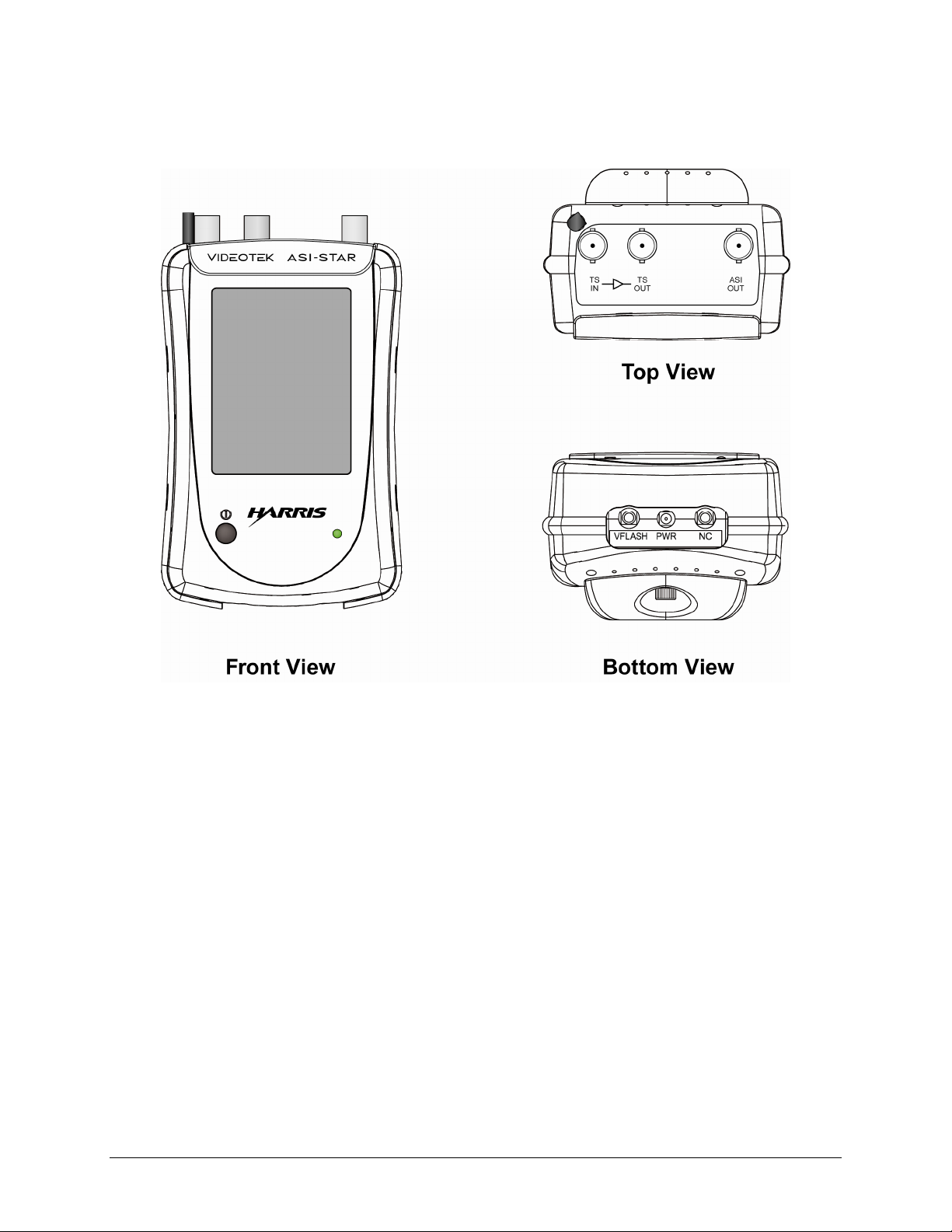
The ASI-STAR views are illustrated in Figure 1-1.
Figure 1-1. ASI-STAR Views
1-2 ASI-STAR Installation and Operation Handbook
Page 13

Introduction
Service and Support
For service support, telephone the Customer Service Department at 888-534-8246. If the
problem cannot be resolved over the telephone and the instrument must be shipped to Harris for
service or repair:
• Obtain a Return Authorization (RA) number from the Harris Customer Service Department.
• Attach a tag to the unit with:
− Your company name, address, and telephone number
− The name of the contact person at your company
− The RA number
− The unit serial number
− An explanation of the problem
• To prevent shipping damage, pack the unit the in the manner that it was packed when
received when returning for service. If possible, use the original packing materials in the
original shipping container.
• Ship the unit to:
Harris Corporation
Videotek Test and Measurement
243 Shoemaker Road
Pottstown, PA 19464-6433
Attn: RA xxx (where x is the RA number)
Email: BCDService@harris.com
ASI-STAR Installation and Operation Handbook 1-3
Page 14

Introduction
This page is intentionally blank.
1-4 ASI-STAR Installation and Operation Handbook
Page 15

Section 2 ♦ Installation
This section provides information about inspecting, installing, and configuring the ASI-STAR.
Inspecting the Shipment
Before using the ASI-STAR, inspect the box and the contents. Report any damage to the shipper
and telephone the Harris Customer Service Department for service and support (see Section 1,
“Service and Support“).
NOTE: Refer to the enclosed packing sheet for the latest list of items that are supplied with the unit.
The box contains the following:
• One ASI-STAR
• One Star Series CD containing the ASI-STAR Installation and Operation Handbook
• One power adapter and cord
• One stylus
• One sunshield
• One belt-style pouch
• USB to RS-232 adaptor with cable
• One 6-in. long 9-pin D-sub to 3.5 mm connector cable
• One lithium ion battery pack installed
• One compact flash card 2GB 266x
Save the box and packing material for any future shipping requirements.
ASI-STAR Installation and Operation Handbook 2-1
Page 16
Installation
Connecting the ASI-STAR
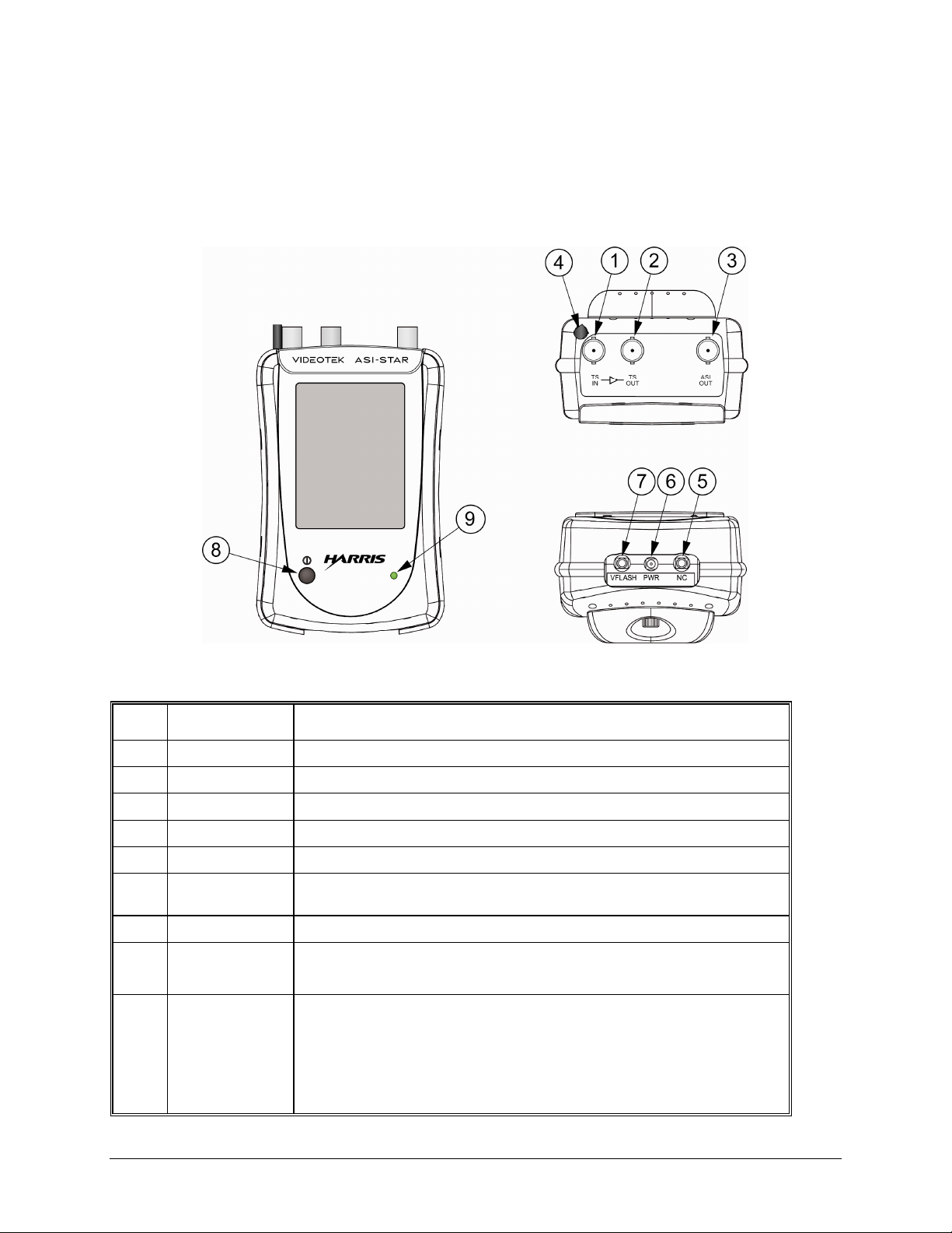
The ASI-STAR connectors and features are illustrated in Figure 2-1, and the function of each is
described in Table 2-1.
Figure 2-1. ASI-STAR Panel
Table 2-1. Description of ASI-STAR
Key Label Description
1 TS IN DVB-ASI or SMPTE-310M active-looping input
2 TS OUT DVB-ASI or SMPTE-310M active-looping output
3 ASI OUT Play-out of DVB-ASI transport stream from the compact storage device
4 Stylus Container Stylus storage for when the stylus is not in use.
5 NC No Connection
6 PWR Micro-miniature, female, Power connector to receive the 5.0V DC to charge
the lithium battery and/or power the ASI-STAR.
7 VFLASH Used for updating firmware via computer
Θ
8
9 LED Multi-colored LED to indicate battery charge status:
Power
Button
Press and release to turn the ASI-STAR ON.
Press and release to turn the ASI-STAR OFF.
Yellow – low battery charge. When the Lithium Battery is installed, the
LED will only turn yellow when the battery is extremely low.
Red – battery is charging
Green – battery charging cycle is complete
2-2 ASI-STAR Installation and Operation Handbook
Page 17
Installation
Battery Pack and Powering Up the ASI-STAR
The ASI-STAR is powered by a lithium ion battery pack that is charged with a power adapter.
When the power adapter is applied, the device can still be in use without affecting charge time.
The front panel LED will turn green when the battery charging cycle is complete. The unit
should be charged for 8 hours before using the unit for the first time on battery power.
Battery Saver mode in the System Setup menu is used to darken the display in order to save
battery power. The LCD backlight is disabled when Battery Saver mode is activated. This greatly
extends the battery life. The Battery Saver mode selections are Off, 1 minute, 5 minutes
(default), 10 minutes, or 20 minutes. The test signal outputs continue to function when in Battery
Saver mode. To exit Battery Saver mode, touch anywhere on the screen with the stylus.
Recharging the Unit
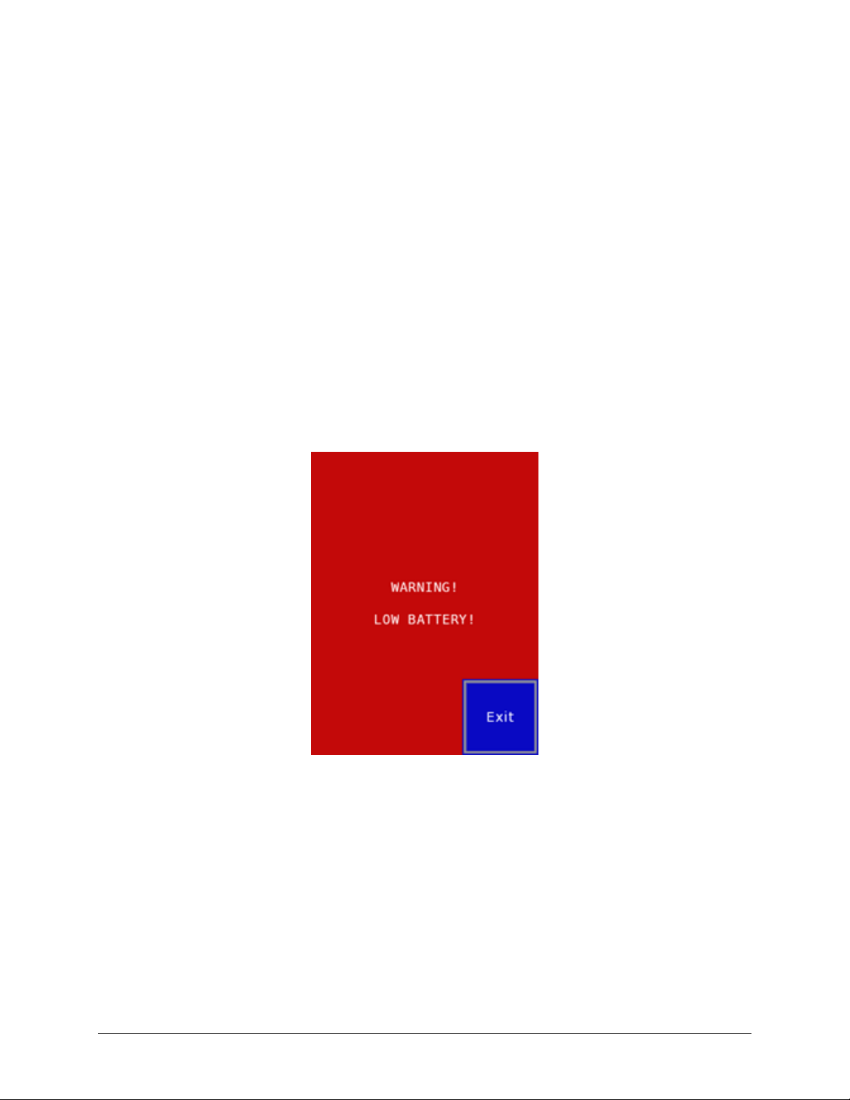
A warning dialog pops up when the battery reaches 10% capacity. At 5% capacity, it pops up
again. See Figure 2-2.
Figure 2-2. Low Battery Warning
When this warning appears, either plug the power adapter into the ASI-STAR to recharge the
unit or replace the lithium ion battery pack.
Shortly after WARNING BATTERY LOW is displayed, the batteries reach a critical level. If
you attempt to power on the unit at this point, it will turn on briefly and then shut off within a
few seconds.
When the battery pack is completely discharged, the unit shuts down automatically.
The battery charging circuit has a built-in timer to protect against damaging the batteries from
overcharging. A battery pack that is very low may take longer to charge to full than the timer
allows. The charge time can be reset during the charge cycle (approximately four to seven hours
into the charge) by removing the external power plug from the unit for a few seconds, and then
reconnecting it.
ASI-STAR Installation and Operation Handbook 2-3
Page 18

Installation
When the EXPECTED TIME TO BATTERY EMPTY displays 3 MINUTES (next to the battery
symbol), the unit briefly displays BATTERY EXHAUSTED prior to powering down. Recharge
the battery pack installed in the device using the power adapter. (Connect the power adapter to
the AC outlet and the PWR connector of the GEN STAR.) The front panel LED will turn green
when the battery charging cycle is complete.
Replacing the Battery Pack
WARNING: Do not puncture, damage, or discard batteries in fire. The batteries can explode,
releasing hazardous chemicals. Dispose of the batteries according to the instructions of the
battery manufacturer and in accordance with local laws.
The lithium ion battery pack is installed at the Harris manufacturing facility. A new battery pack
can be ordered from the Harris Customer Service department
If the lithium ion battery pack needs to be replaced, perform the following:
1. Unscrew the thumbscrew on the battery compartment lid on the back of the ASI-STAR.
2. Remove the old lithium ion battery pack from the CN9 connection inside the battery
compartment.
3. Plug the new lithium ion battery pack into the CN9 connection inside the battery
compartment.
4. Insert the new lithium ion battery pack into the battery compartment.
5. Place the battery compartment lid back onto the ASI-STAR, and then secure the lid using the
thumb screw.
6. Connect the power adapter to the AC outlet and the PWR connector of the ASI-STAR.
7. The unit should be charged for eight hours before using the unit for the first time on battery
power.
Press and hold the power button until the LCD backlight illuminates to activate the unit. Allow a
few seconds for the unit to initialize.
Configuring the ASI-STAR
The ASI-STAR does not have any specialized configuration procedures. Use of ASI-STAR
menus and buttons are described in Section 3, “General Operation.”
2-4 ASI-STAR Installation and Operation Handbook
Page 19

Section 3 ♦ General Operation
Information Display
The Information Display is shown in Figure 3-1.
Figure 3-1. Information Display
The ASI-STAR information display is the first screen to appear after the unit is powered on. The
battery icon indicates the remaining time of the charge. If the unit is operating off of an external
power supply, the icon appears as shown in Figure 3-2 along with “External Power”.
Figure 3-2. Alternate Screen Display
All menus are accessed by touching or lightly tapping the appropriate icon with the supplied
stylus. Using the stylus avoids build-up of oil on the screen, which can occur when using your
fingers to move through the menus. It is also not recommended to use a pen or pencil to tap on
the icons.
• The MAIN MENU icon is used to return to the main menu by tapping the stylus on the Main
Menu icon.
ASI-STAR Installation and Operation Handbook 3-1
Page 20

General Operation
• The SYSTEM SETUP icon is used to access the System Setup display. The System Setup
display is used to change the configurations of the ASI-STAR. For more information on the
System Setup display, see Figure 3-3 and the paragraphs that follow.
• The STATUS icon is used to access the bandwidth display. See Figure 3-10 and the
paragraphs that follow.
• The TABLE SELECT icon is used to access the ATSC-PSIP or DVB-SI tables, transport
stream format and data format selections. See Figure 3-12 and the paragraphs that follow.
• The ALARMS icon is used to access the Alarm Setup and Status display. For more
information, see the Alarms section. See Figure 3-27 and the paragraphs that follow.
• The RECORD & PLAYOUT icon is used to access the record and playout selections. See
Figure 3-34 and the paragraphs that follow.
System Setup
The System Setup is shown in Figure 3-3.
Figure 3-3. System Setup
The System Setup screen consists of the settings to utilize various functions of the ASI–STAR.
The icons include the following:
• MAIN MENU: The MAIN MENU icon is used to return to the Main Menu
• ABOUT: Displays revision information for the unit as shown in Figure 3-4. The first line
below the product name displays “Default firmware” if the unit is operating with the original
factory loaded code. If the unit has been upgraded, it displays “Updated firmware.”
The information below displays the Firmware versions. Letters A through F show versions of
various hardware and software installed on the ASI-STAR. The letter “A” indicates the .flu file
version; this information may be requested when calling Harris Corporation for servicing of the
unit.
3-2 ASI-STAR Installation and Operation Handbook
Page 21

General Operation
Figure 3-4. About Display
SYSTEM RESET: Tap the System Reset icon to reset all configurations to default values and
return to the main menu.
Tap Cancel to abort system reset.
Figure 3-5. System Reset
ASI-STAR Installation and Operation Handbook 3-3
Page 22

General Operation
BATTERY SAVER: Configures the time delay after the last touch screen activity before the
backlight is turned off to conserve battery power.
Figure 3-6. Battery Saver
TIME ZONE: Configures the local time zone, which affects table data display. Use the stylus
and tap on the arrows to adjust the time zone selection. This feature modifies the time displayed
in the STT, EIT, EPG for the ATSC tables and EIT and EPG for the DVB tables.
Figure 3-7. Time Zone
3-4 ASI-STAR Installation and Operation Handbook
Page 23

General Operation
DATA FORMAT: Data Format affects all table displays and configures table data displays in
hexadecimal (base 16) number format or decimal (base 10) number format, as shown in Figure
3-9.
Figure 3-8. Data Format
Figure 3-9. Program Association Table (PAT) Data Format Configurations
PAT in Hexadecimal Number Format (Base 16)
PAT in Decimal Number Format (Base 10)
ASI-STAR Installation and Operation Handbook 3-5
Page 24

General Operation
Status/Info Display
Tap the STATUS icon on the MAIN MENU. At the top of the display is PROGRAM, indicating
the number of the current program. Below that is TOTAL, indicating the number of programs
available on the transport stream input, as shown in Figure 3-10.
Figure 3-10. Status/Info Display
Tap the arrow to select a previous or a next program when multiple programs are available.
The table is comprised of four columns.
• Column 1 is the assigned index of the program data stream in the order received.
• Column 2 is the PID of the stream.
• Column 3 is the data type, which could be video, or audio, or raw data.
• Column 4 shows the data rate of the data stream.
The program total indicates the bandwidth for the selected program.
If more than 2 streams are present on the program, scroll bars will appear on the right side of the
screen for use in selecting additional streams.
TS Total represents the active data bandwidth in the transport stream.
NULL Bandwidth (B/W) represents the NULL packet bandwidth in the transport stream.
Total Bandwidth (B/W) represents the total bandwidth of the transport stream and is the sum of
TS Total and NULL B/W.
The center icon is separated into three sections to indicate the current display, input format
(ASI/SMPTE 310), and alarm status (refer to Figure 3-10). The word ALARM is shaded in gray
if all alarms are disabled; shaded with green if one or more alarms are enabled, and none are
triggered; and shaded with red if one or more alarms are enabled, and one or more are triggered.
Tap the ALARM icon to activate the Alarms screen.
3-6 ASI-STAR Installation and Operation Handbook
Page 25

General Operation
Table Selection
The Table Selection menu is used to access the different tables available in the transport stream.
Select TS Format (DVB or ATSC) to change the Transport Stream format, as shown in Figure
3-11.
Figure 3-11. Transport Stream Format
The ATSC and DVB format table selections are shown in Figure 3-12.
Figure 3-12. Table Selection Menu
ATSC Format
Table Selections
DVB Format
Table Selections
ASI-STAR Installation and Operation Handbook 3-7
Page 26

General Operation
ATSC Tables
The following table information is from reference standard ATSC A/65.
PAT (Program Association Table)
There is one PAT for each program as shown in Figure 3-13. This display also appears in the
DVB Transport Stream format.
Figure 3-13. PAT Selection
PMT (Program Map Table)
There is one PMT for each program, as shown in Figure 3-14. This display also appears in the
DVB Transport Stream format.
Each stream in the program is displayed in two rows, with the first row broken into three
columns:
• Column 1 indicates the received order of the program streams.
• Column 2 is the PID value of the stream.
• Column 3 is the stream type displayed as a number.
The second row displays the stream type as text.
If more than two streams are present on the program, scroll bars on the right side of the screen
will allow stream selection.
3-8 ASI-STAR Installation and Operation Handbook
Page 27

General Operation
Figure 3-14. PMT Selection
MGT (Master Guide Table)
All entries are sorted by type, and each entry is displayed in two rows, with the first row broken
into three columns.
• Column 1 is the MGT entry index.
• Column 2 is the data type displayed as a number.
• Column 3 is the type, displayed as text
The second row is broken into two columns:
• Column 1 displays the PID containing the data.
• Column 2 displays the data version.
The MGT is not specific to a program, so the program selector does not appear. When more than
three entries are present in the MGT, scroll bars appear on the right side of the screen as shown
in Figure 3-15.
ASI-STAR Installation and Operation Handbook 3-9
Page 28

General Operation
Figure 3-15. MGT Selection
VCT (Virtual Channel Table)
The VCT spans two pages; there is one VCT for each program. On the right side of the screen is
an up or down arrow for selecting page 1 or page 2, as shown in Figure 3-16.
Figure 3-16. VCT Selection, Pages 1 and 2
Page 1 of VCT Selection Page 2 of VCT Selection
3-10 ASI-STAR Installation and Operation Handbook
Page 29

RRT (Regional Rating Table)
The RRT is not specific to a program.
Figure 3-17. RRT Selection
General Operation
STT (System Time Table)
The STT is not specific to a program. The Local time displayed is set using the Time Zone menu
in the main System Setup menu.
Figure 3-18. STT Selection
EIT (Event Information Table) ATSC version
NOTE: See Figure 3-25 for an illustration of the EIT selection for DVB.
There is one EIT for each program as shown in Figure 3-19. EIT entries are sorted by Event ID.
To select one, use the stylus on the scroll bars on the right of the screen. The events are color
coded using information from the STT.
ASI-STAR Installation and Operation Handbook 3-11
Page 30

General Operation
• Events that occurred in the past are displayed in brown.
• Events occurring now are displayed in white.
• Events that will occur in the future are displayed in green.
• If the STT is not present on the transport stream, all events are displayed in white.
Figure 3-19. EIT Selection for ATSC
EPG (Electronic Program Guide) ATSC version
NOTE: See Figure 3-26 for an illustration of the EPG selection for DVB.
There is one EPG for each program as shown in Figure 3-20. EPG entries are sorted by Starting
Time. To select one, use the stylus on the scroll bars on the right of the screen. The events are
color coded using information from the STT.
• Events that occurred in the past are displayed in brown.
• Events occurring now are displayed in white.
• Events that will occur in the future are displayed in green.
• If the STT is not present on the transport stream, all events are displayed in white.
3-12 ASI-STAR Installation and Operation Handbook
Page 31

General Operation
Figure 3-20. EPG Display for ATSC
Shown here are three available programs. The highlighted text with the box surrounding it
indicates that this program is selected. Tap this highlighted text with the stylus to see the
complete text information (see Figure 3-21) from the ETT (Extended Text Table) associated
with this program event.
Figure 3-21. ETT Display
ASI-STAR Installation and Operation Handbook 3-13
Page 32

General Operation
DVB Tables
The following table information is from DVB reference standard ETSI EN 300 468.
CAT (Conditional Access Table)
This is not associated with any specific program, but is global to the entire transport stream. See
Figure 3-22.
Figure 3-22. CAT Display
NIT (Network Information Table)
This is not associated with any specific program. If multiple transport streams are described in
the NIT, scroll bars appear for selecting various transport streams.
The Transport Stream Identification (TSID) and Original ID are displayed for each transport
stream described in the NIT. See Figure 3-23.
Figure 3-23. NIT Display
3-14 ASI-STAR Installation and Operation Handbook
Page 33

General Operation
SDT (Service Description Table)
The information displayed is specific to this program. A sample display is shown in Figure 3-24.
Figure 3-24. SDT Display
EIT (Event Information Table) DVB version
NOTE: See Figure 3-19 for an illustration of the EIT selection for ATSC.
There is one EIT for each program as shown in Figure 3-25. EIT entries are sorted by Event ID.
To select one, use the stylus on the scroll bars on the right of the screen. The events are color
coded using information from the TDT.
• Events that occurred in the past are displayed in brown.
• Events occurring now are displayed in white.
• Events that will occur in the future are displayed in green.
• If the TDT is not present on the transport stream, all events are displayed in white.
Figure 3-25. EIT Selection for DVB
ASI-STAR Installation and Operation Handbook 3-15
Page 34

General Operation
EPG (Electronic Program Guide) DVB version
NOTE: See Figure 3-20 for an illustration of the EPG selection for ATSC.
There is one EPG for each program as shown in Figure 3-26. EPG entries are sorted by Starting
Time. To select one, use the stylus on the scroll bars on the right of the screen. The events are
color coded using information from the TDT.
• Events that occurred in the past are displayed in brown.
• Events occurring now are displayed in white.
• Events that will occur in the future are displayed in green.
• If the TDT is not present on the transport stream, all events are displayed in white.
Figure 3-26. EPG Selection for DVB
Alarms
Figure 3-27. Initial Alarm Display (Default State)
3-16 ASI-STAR Installation and Operation Handbook
Page 35

General Operation
Different background colors indicate the status of each alarm. Gray indicates the alarm is not
enabled. Green indicates the alarm is enabled but not triggered (no error condition), and red
indicates the alarm is enabled and triggered (error condition).
Each alarm acts as a pushbutton. When the icon is tapped, a pop-up menu appears that can be
used to configure the alarm. The Enable Alarm icon toggles alarm enable on/off. The arrows are
used to change the duration setting if the alarm has that capability as shown in Figure 3-28.
Figure 3-28. Configuring the Alarm
ALARM COUNT TYPE: There are three types of alarm counts: Error Count, Time Since Error,
and Error Free Time. Tap the icon in lower right corner of screen to access the alarm count type
menu to change the alarm status display between error count, time since error, and error free
time, shown in Figure 3-29. The Clear Counts icon resets the counts for all alarms. Use it to
reset Error Count to zero, Time Since Error to --:--:--, and Error Free Time to 100%.
Figure 3-29. Resetting the Alarm Counts
ERROR COUNT: At the far right in each row is the error count. The number indicates how
many times the alarm occurred that was not previously occurring (rising edge of alarm) as shown
ASI-STAR Installation and Operation Handbook 3-17
Page 36

General Operation
in Figure 3-30. In this example, Sync Loss alarm is enabled and the 1 indicates that there had
been one alarm occurrence. The green indicates that Sync was lost but has been re-established.
Figure 3-30. Error Count
ERROR FREE TIME: At the far right in each row is the Error Free Time. This is the ratio of
time with no error, vs. total elapsed time as shown in Figure 3-31. In this example, PID Error
alarm is enabled and is triggered as indicated by the red background.
Figure 3-31. Error Free Time
TIME SINCE ERROR: The amount of time that has elapsed since the error last occurred is
shown at the far right in each row (see Figure 3-32). If no alarm occurs, or if no alarm is
enabled, or if error count is cleared, then - - : - - : - - is displayed at the far right of each row (see
Figure 3-33).
The maximum time that can be displayed after the last error is 24:00:00+.
3-18 ASI-STAR Installation and Operation Handbook
Page 37

General Operation
Figure 3-32. Time Since Error
In the example shown in Figure 3-33, the Sync Loss error is occurring, resulting in Time Since
Error displaying zero. The Sync Byte error ended and last occurred 2 minutes, 36 seconds ago.
The other alarms never occurred, resulting in an error display of - - : - - : - - .
Figure 3-33. Errors Not Available
ASI-STAR Installation and Operation Handbook 3-19
Page 38

General Operation
Record & Playout
Figure 3-34. Record & Playout Menu
Volume Name is the volume name of the Compact Flash card. The capacity of the card and
amount of remaining free space of the card is shown under the name. The Current File lists the
name of the file that will be played. The Mode shows the status of the transport stream recorder /
player.
Figure 3-35 shows the record/playout menu if a Compact Flash card is inserted in the slot, but it
is not formatted for the FAT32 or FAT16 file system.
Figure 3-35. Record/Playout with Compact Flash Card Installed
3-20 ASI-STAR Installation and Operation Handbook
Page 39

General Operation
Figure 3-36 shows the record/playout menu if no Compact Flash card is inserted in the slot.
Figure 3-36. Record/Playout with No Compact Flash Card Installed
• Tap the File Manager icon to open a file browser menu to select, play, and delete files. See
Figure 3-39.
• Tap the Play icon to play the current file as listed in the display. The file plays until it is
finished, then playout ends. In PLAYBACK mode, only Main Menu and Stop are available.
Figure 3-37. Playback Mode Menu
• Tap the Loop icon for the file playout to repeat continuously.
• Tap the Record icon to record the transport stream into a new file. The ASI-Star generates
the file name “CAPTxxxx.ts”, whereas “xxxx” is a sequential number from 0000 to 9999. In
the RECORDING Mode, only Main Menu and Stop are available.
ASI-STAR Installation and Operation Handbook 3-21
Page 40

General Operation
Figure 3-38. Recording Mode Menu
• Tap the Stop icon to end the record or playout in progress. After tapping stops, a short pause
occurs to allow the system to close the file properly. Do not remove the flash card or power
cycle during this pause. After the file closes, the Mode displays STOPPED.
3-22 ASI-STAR Installation and Operation Handbook
Page 41

File Manager
Figure 3-39. File Manager Menu
General Operation
File Manager displays the list of files in the root directory of the flash card. Only files with the .ts
extension will display. Each file displays the file name and file size (the file name supports a
maximum of eight characters). Scroll arrows appear as necessary.
• To select a file, tap on the file name to highlight it and designate it as the current file.
• Tap the Delete icon to delete the current file.
• Tap the Play icon to play the current file and output to ASI OUT connector.
• Tap the Exit icon to return to the Record & Playout Menu screen (see Figure 3-34).
NOTE: During playout, the ASI-STAR uses PCR information contained in the recorded str eam to generate an ASI output. PCR
errors or disc ontinuities in the recorded stream may compromis e the ability of the ASI-STAR to playout the file correctly. Constant bit
rate transport streams are supported f or ASI playout.
ASI-STAR Installation and Operation Handbook 3-23
Page 42

General Operation
This page is intentionally blank.
3-24 ASI-STAR Installation and Operation Handbook
Page 43

Section 4 ♦ Troubleshooting
CAUTION: These instructions are for use by qualified personnel only. To reduce the risk of
electric shock, do not perform this installation or any servicing unless you are qualified to do so.
Refer all servicing to qualified service personnel.
If the ASI-STAR is not functioning properly, first verify the following:
• The ASI-STAR is connected to a power source (batteries functioning, power plugged into the
unit).
• All cables are correctly connected (see Section 2, “Installation“).
Initial difficulties with operation or display can be due to improper setup. Review Section 3 titled
“Operation” to ensure that the proper adjustments have been made for the signal requirements.
Problems, Causes, and Solutions
Table 4-1. ASI-STAR: Problems, Causes, and Solutions
Problem/Symptom Possible Cause Solution or Explanation
Input is connected but no signal is
detected
WARNING BATTERY LOW
appears on the display
Display goes dark or flashes
between light and dark
Unit does not record
not displayed in the File Manager
The wrong signal format is
applied
Batteries are low Connect the power adapter; the lithium ion
Battery Saver Mode is turned on Change BATTERY SAVER to OFF in the
Compact Flash card is not
installed
Compact Flash card is not
formatted
Compact Flash speed is too low Ensure the Compact Flash speed is 266x
Compact Flash card is full Record/Playback display shows available
File does not have proper
extension file name of “.ts”
File is not in the root directory Move file to the root directory
Check if a valid DVB-ASI or SMPTE-310M
signal is applied
battery pack will recharge while the unit is
operational.
SYSTEM SETUP menu
Ensure the Compact Flash card is installed
Ensure the Com pact Flash card is
formatted as FAT32 or FAT16
space. If card is full, delete unnecessary
files or install new Compact Flash card
Rename file extension to “.ts” File on the Compact Flash card is
Unit does not playout Selected file does not contain a
valid transport stream
Select a file that contains a valid transport
stream
If the problem still exists after troubleshooting the ASI-STAR, see Section 1, “Service and
Support,” for further instructions.
4-1 ASI-STAR Installation and Operation Handbook
Page 44

Troubleshooting
Care and Maintenance
• Do not scratch the screen. Use only the stylus to operate the ASI-STAR. Avoid using sharp
objects to operate the ASI-STAR like pens and pencils.
• Do not use your fingers to operate the ASI-STAR. Oils from fingers will soil the screen.
• If the screen needs to be cleaned, use a soft lint-free cloth moistened with a diluted window-
cleaning solution to clean the ASI-STAR. If the ASI-STAR is utilizing the power adapter,
unplug the adapter before cleaning. Do not use alcohol, aerosol sprays, or abrasives.
• Do not use in rain or areas with heavy moisture.
• Do not charge batteries that are rusty, leaking, or corroded.
• Do not drop the ASI–STAR. A strong impact or it being crushed in any way could damage it.
• Store the unit in a cool, dry area. Avoid dirty, dusty, damp, or wet areas for storage. Also,
avoid areas of extreme hot or cold temperature.
Impairment Clause
Do not use the product in any way beyond its intended use. Using the product beyond the scope
of its design may impair the safety of the device and the user.
VFlash Installation and Update
The ASI-STAR is updated using the VFlash program. Obtain the latest .flu file from the
Support/Software library on the Harris website. Downloads and technical documentation are
located in the Premier Customer Support Site, which is linked to the Harris Support and Training
> Broadcast Communications Division web page.
Follow the instructions in the VFlash User Guide located on the VFlash CD to update the device.
To perform a VFlash update:
1. Connect the ASI-STAR to the PC using the supplied adaptor cable. Insert the 3.5 mm plug
into the VFLASH connector, and the 9-pin D-Sub connector into the PC, optionally using the
supplied USB to RS-232 adaptor.
NOTE: The supplied USB-to-serial adaptor may be used. The USB adaptor will require installation of certain
drivers from the manufacturer-supplied CD. See the manufacturer’s instructions for more information.
2. Run the VFlash program on a PC. In the VFlash Config menu, set the communications to
115200 baud, no parity, 8 data bits, 1 stop bit.
3. Set the Unit ID to 1, and the interface to Serial. At the start of the flash update procedure, the
ASI-STAR will display the flash update status screen (see Figure 4-1). During a
communications error, the display will appear as in Figure 4-2.
4-2 ASI-STAR Installation and Operation Handbook
Page 45

Figure 4-1. Flash Update Status Screen
Figure 4-2. Communications Error
Troubleshooting
4. If a communications timeout occurs, the flash update will fail. The unit must be turned off
and then powered on again, which will result in the ASI STAR reverting back to the default
software.
5. If the flash update is successful, the display will appear as shown in Figure 4-3.
ASI-STAR Installation and Operation Handbook 4-3
Page 46

Troubleshooting
Figure 4-3. Flash Update Successful
6. Cycle power on the ASI-Star.
7. The update can be verified by the About display (see Figure 3-4) under the heading
“Updated Firmware.”
4-4 ASI-STAR Installation and Operation Handbook
Page 47

Appendix A ♦ Specifications
Specifications are subject to change without notice.
Table A-1. Transport Stream Input Specifications
Item Specification
Number One Transport Stream input: DVB-ASI or SMPTE-310M active looping
Connector Two Female BNC connectors
Impedance
Return Loss ≥ 15 dB
Frequency Range 5 MHz to 270 MHz
Level 0.8 volt p-p nominal
Standards Auto detects DVB-ASI or SMPTE-310M
Table A-2. Transport Stream Output Specifications
Item Specification
Connector 1 female BNC connector
Impedance
Standard DVB-ASI
Return loss ≥ 15 dB
Frequency range 5 MHz to 270 MHz
Table A-3. Compact Flash Specifications
75Ω
75Ω
Item Specification
Speed 266x, UDMA Mode 4 (Sustained read/write speed must be at
least 30 MB/sec for optimal performance)
Power 3.3V, 75 mA (Power Level 0)
ASI-STAR Installation and Operation Handbook A-1
Page 48

Specifications
Table A-4. Display Specifications
Item Specification
Display Type Color Monitor Touch Screen
Resolution 320×240 RGB pixels (picture)
Display Area 2.1 in.×2.8 in. (54 mm×72 mm)
Backlight White LED
Table A-5. Power Requirements Specifications
Item Specification
Power adapter Input: 100 – 240 VAC, 50/60 Hz, 0.7A Minimum
Output: 5.0V VDC at 3A Minimum
Battery 1 lithium ion battery pack
Power management Auto shutdown of display
Installation Category Category I
Note: See page C-5 for Installation Category descriptions.
Table A-6. Mechanical Specifications
Item Specification
Dimensions Height: 5.9 in. (15 cm)
Width: 3.7 in. (9.4 cm)
Depth: 2.5 in. (6.35 cm)
Weight 15.8 oz (448 grams)
Table A-7. Environmental Specifications
Item Specification
Operating temperature
Storage Temperature
Transportation 24 in. (60.96 cm) impact-drop survivable in original factory packaging
0° to +40°C
-30° to +85°C
Pollution Degree Pollution Degree 2
Note: See page C-7 for Pollution Degree descriptions.
A-2 ASI-STAR Installation and Operation Handbook
Page 49

Appendix B ♦ Pinouts
Figure B-1. Power Connector
Figure B-2. Phone Jack Connector
Table B-1. VFlash Connector Pinouts
Pinout VFLASH
SLEEVE GND
TIP Receive
RING Transmit
ASI-STAR Installation and Operation Handbook B-1
Page 50

Pinouts
This page is intentionally blank.
B-2 ASI-STAR Installation and Operation Handbook
Page 51

Appendix C ♦ Glossary
601 An international standard (ITU-R BT.601) for component digital television. It defines the
sampling systems, matrix values, and filter characteristics for digital television.
8 VSB Vest igial sideband modulation with 8 discrete amplitude levels.
16 VSB Vestigial sideband modulation with 16 discrete amplitude levels.
Advanced Television Systems Committee (ATSC) The parent organization that
developed, tested and described the form and function of the US digital television formats.
AES/EBU A digital audio standard established jointly by the Audio Engineering Society (AES)
and the European Broadcasting Union (EBU).
Artifacts Unwanted visible effects in the picture created by disturbances in the transmission or
image processing, such as edge crawl or ‘hanging dots’ in analog pictures or ‘pixilation’ in
digital pictures.
Aspect Ratio The ratio of horizontal to vertical dimensions. A square has an aspect of 1:1 since
the horizontal and vertical measurements are always equal. Current television screen aspect
ratios are 4:3 and 16:9.
Asynchronous Serial Interface (ASI) A transmission method adopted by the DVB, and
called DVB-ASI. The transmission method allows for the transport of varying data payloads in a
constant data stream. The DVB-ASI transport stream rate is 270 Mb/s.
Audio Breakaway Routing video and accompanying audio in separate signal paths.
Audio-Follow Routing video and accompanying audio together in the same signal path.
Auto Trans Automatic transition. The execution of a single wipe or fade from current picture to
another picture by way of an automatic device.
Bandwidth The range of frequencies used to transmit information such as picture and sound.
Baseband Video An unmodulated video signal.
Black Also color black, black burst. A composite color video signal that has the composite sync,
reference burst, and a black video signal.
Blanking Processor A circuit which removes sync, burst and blanking from the program
video and then replaces it with sync, burst and blanking from the reference input. The process
ensures constant sync and burst levels on program video.
Border An electronically-generated picture member which is used in wipes to separate the two
video sources used in the wipe. It is of even thickness and has color produced by the matte
generator.
Broadcast Legal Encoding video signal parameters to conform to prescribed limits for
broadcast. Encoding rules vary by NTSC, PAL, country and broadcast facility.
BTSC Broadcast Television Standards Committee. A US standard for stereo audio encoding in
NTSC broadcast television.
CAV Component Analog Video
ASI-STAR Installation and Operation Handbook C-1
Page 52

Glossary
CES Consecutive Errored Samples
Composite Video A single video signal that includes all color video and timing information. A
composite signal includes luminance, chrominance, blanking pulses, sync pulses and color burst
information.
Chrominance The color portion of a video signal that represents the saturation and hue. Black,
gray and white have no chrominance; color signals have both chrominance and luminance.
CH Chroma
Chrominance/Luminance Delay (C/L Delay) A measurement that indicates the amount to
which chrominance and luminance are aligned with respect to each other. A low C/L delay figure
can minimize the effects of ghosts or color offset on the received picture.
Clipping The electronic process of shearing off the peaks of either the white or black excursions
of a video signal for limiting purposes. Clipping is often performed prior to modulation to limit
the signal.
CMRR Common Mode Rejection Ratio
Color Burst The portion of a color video signal which contains a short sample of the color
subcarrier. It is used as a color synchronization signal to establish a reference for the color
information following it and is used by a color monitor to decode the color portion of a video
signal. The color burst acts as both amplitude and phase reference for color hue and intensity.
The color oscillator of a color television receiver is phase locked to the color burst.
Composite Sync A signal consisting of horizontal sync pulses, vertical sync pulses and
equalizing pulses only.
CRC Cyclical Redundancy Check
Crosspoint An electronic switch, usually controlled by a button on the panel. Control logic will
allow for only one crosspoint, for each bus, to be switched “ON” on at a time.
D/A Conversion of digital to analog signals.
DA Distribution Amplifier
Data Element An item of data as represented before encoding and after decoding.
Decoded Stream The decoded reconstruction of a compressed bit stream.
Decibel (dB) A logarithmic measure of the ratio between two powers, voltages, currents, sound
intensities, etc. Signal-to-noise ratios are expressed in decibels.
Default A factory preset value or condition.
Demodulator A receiver, such as for television broadcast, cable, and closed circuit
applications. A TV demodulator receives and processes off-air or cable RF signals and provides
baseband video and audio outputs.
DHCP Dynamic Host Configuration Protocol
Differential Gain A measurement that specifies how much the chrominance gain is affected by
the luminance level. Expressed as a percentage showing the largest amplitude change between
any two levels, it indicates how much color saturation variance occurs when the luminance level
changes.
C-2 ASI-STAR Installation and Operation Handbook
Page 53

Glossary
Differential Phase A peak-to-peak measurement that specifies the extent to which the
chrominance phase is affected by the luminance level. Expressed in degrees of subcarrier phase,
it indicates how much hue shift occurs with luminance level changes.
Digital Video Broadcasting (DVB) A specific project office of the European Broadcast
Union. This group has produced a set of digital broadcasting standards.
DSK Down Stream Key, a keyer which is electronically located after (or down stream from) all
other functions of a switcher. The key resulting will appear to be on top of all other pictures from
the switcher.
D-VITC Digital Vertical Interval Time Code. Timecode information stored on specific lines in
the vertical blanking interval of a television signal.
EAV End of Active Video in component digital systems.
EBU European Broadcasting Union
Editor A device or system which controls video tape recorders, video switchers, and other
related devices in order to electronically splice segments of recorded video into a finished
production.
EDH Error Detection and Handling. A recommended practice defined in SMPTE RP 165. A
system to generate and then detect video data errors in serial digital video systems.
Effects Keyer A keyer which is electronically located in the mix/wipe generator portion of a
switcher. The resulting key would appear under the down stream key.
EIA Rack Space or Unit A specific size as designated by the Electronics Industry
Association. The rack unit is 19 inches wide, and is 1.75 inches tall. A device which requires 3
EIA rack units is 19 inches wide and 5.25 inches (3x1.75 = 5.25) tall.
Elementary Stream (ES) A generic term for one of the coded video, audio or other variable
length bit streams which are packetized to form MPEG-2 transport streams. Consists of
compressed data from a single source (audio, video, data, etc.). One elementary stream is carried
in a sequence of PES packets with one and only one stream ID.
Embedded Audio Digital audio information multiplexed onto a serial digital data stream. Up
to sixteen channels can be multiplexed on a single stream of 601 video, minimizing cabling and
routing requirement.
ENG Electronic News Gathering
Encoded Clip Softness In the encoded legalization process, “softness,” as applied to encoded
clips, refers to the processing of the video at the point of the clip. The clips are applied in YCBC
R
color space. The clip point is either an immediate limit (no softness) or will have a range of
values leading to the clip point, all reduced to smooth the clip point to a less immediate limit
(softness).
Encoded Legalization Limiting of the luminance and color difference signals such that, once
encoded into a composite video signal, the resultant encoded video does not violate the
maximum or minimum signal levels as defined by the specific encoding rules. NTSC and PAL
video plus various users of these types of video have many varied rules for maximum and
minimum encoding limits. Encoded legalization usually calculates first the encoded luminance
value and then the corresponding chroma value to make legalization judgments.
ASI-STAR Installation and Operation Handbook C-3
Page 54

Glossary
Encoded Video A combined single video signal that is constructed from either separate GRB
or luminance and two color difference video signals. NTSC, PAL, and SECAM are all examples
of encoded video.
Envelope Detection An RF signal detection technique that does not respond to phase
variations in the carrier signal, enabling measurement of a transmitter’s incidental phase. When
used together with synchronous detection, envelope detection helps isolate either video and/or
RF as the causes of phase distortion.
External Key Input This is an alternate source for key cut. This is usually a separate external
input to a switcher
Fade-thru-Black A production technique which is a two step process. The first step will fade
the program video to black. The second step will fade from black to the video selected on the
preview bus. This is usually used in major scene transitions.
Fade-to-Black A production technique which simply fades the program video to black and
program audio to silent. This is used to end programs and to escape from embarrassing pictures
or sounds.
Field A picture or picture portion which is produced within one cycle of vertical
synchronization. In interlaced systems, a full picture or frame requires two consecutive fields.
FM Trap A circuit designed to minimize potential interference from strong FM signals in
receiving equipment, such as a TV demodulator. For example, an FM trap can attenuate signals
between 88-108 MHz to reduce interference on NTSC television channel 6.
Frame A single full resolution picture as viewed in either a video or film system. In the case of
interlaced video, two consecutive fields provide all of the information of one frame. In noninterlaced systems, one cycle of vertical synchronization produces a frame. A 60 Hz interlaced
system, produces 30 frames of video in one second. A 60 Hz progressive (or non-interlaced)
system, produces 60 frames of video in one second. Common frame rates are 24 (film) 25, 29.97,
30, 50, 59.94 and 60.
Frame Synchronizer An electronic device that synchronizes two or more video signals. Using
one input as a reference, it locks a second signal to the reference.
Frame Store An electronic method of capturing and storing a single frame of video.
Gamma This term applies to the linearity of the change from black to white. Gamma controls
adjust the gray or 50% point of the video either up or down, with the effect of changing the gray
level of the video.
Gamut The whole or total of whatever is being addressed. In color space, gamut refers to all
colors which are included in a particularly defined color group, such as 601 gamut.
Genlock (Generator Lock) A method of synchronization involving the generation of a video
signal that is time and phase locked with another signal.
GPI General Purpose Interface
Headend In a cable TV system, the facilities where program sources (satellite, terrestrial, VTR,
local) are received and remodulated for distribution through a cable plant.
C-4 ASI-STAR Installation and Operation Handbook
Page 55

Glossary
High Definition Television (HDTV) High definition television has a resolution of
approximately twice that of conventional television in both the horizontal (H) and vertical (V)
dimensions and a picture aspect ratio (H to V) of 16:9.
High Level A range of allowed picture parameters defined by the MPEG-2 video coding
specification which corresponds to high definition television.
HRC Harmonically-Related Carrier
Hue Color tint
ICPM Incidental Carrier Phase Modulation. A measurement of picture carrier phase distortion
(affected by the video signal level) that occurs in the transmitter.
Installation Categories Categories of measurements that occur on circuits attached or not
attached to a live electrical supply outlet. Installation Categories are as follows:
• Category I is for measurements that occur on circuits not attached to a live electrical
supply outlet (115/230 VAC). The voltages come from secondary power sources. The
secondary power source includes circuits energized by low-voltage sources and
electronics such as batteries.
• Category II is for measurements that occur on circuits attached to a live electrical
supply outlet (115/230 VAC).
• Category III is for measurements that occur on equipment permanently connected to the
building. The distribution level equipment are usually fixed installations and circuit
breakers.
• Category IV is for measurements that occur at the main electrical power supply.
IP Internet Protocol
IRC Incrementally-Related Carrier
I.R.E. Refers to the Institute of Radio Engineers, and is used as a unit of measurement. In NTSC
television, 1 volt of signal equals 140 IRE units.
ISP Internet Service Provider
Jitter A deformation of a signal affected by poor synchronization.
Key An effect in television where a selected portion of background video is removed and
replaced with another video.
Key Cut In a key effect, this is the video which designates the portion of background video
which is removed.
Key Fill In a key effect, this is the video which is used to replace the portion of background
video which was removed. This may be the same video as the Key Cut video.
Key Invert In a key effect, this is an electronic action which reverses the polarity of the key cut
signal. It makes black appear as white, and white appear as black.
Key Mask In a key effect, it uses a wipe pattern from the wipe pattern generator to restrict the
key cut from removing video in a portion of the screen. This requires the use of the wipe pattern
generator and the Mask/Preset Size controls.
Key Source Another term which is the same as key cut.
ASI-STAR Installation and Operation Handbook C-5
Page 56

Glossary
Legalization The modification of serial digital video to conform to analog color space rules, as
required by users.
LCD Liquid Crystal Display
LED Light-Emitting Diode
LFE Low Frequency Effects
Lissajous A display of the amplitude and phase relationships between two input signals.
LS Left Surround
LTC Longitudinal Time Code, A SMPTE timecode standard usually recorded onto the linear
audio track of a VTR.
Luminance The degree of brightness (black and white portion of the video signal) at any given
point in the video image. A video signal is comprised of luminance, chrominance and sync. If
luminance is high, the picture is bright and if low the picture is dark. Changing the chrominance
does not affect the brightness of the picture.
Main Level A range of allowed picture parameters defined by the MPEG-2 video coding
specification with maximum resolution equivalent to standard definition television.
Main Profile A subset of the syntax of the MPEG-2 video coding specification that is supported
over a large range of applications. Applications include, MP@HL (Main profile at high level)
and MP@ML (Main profile at main level).
Mask/Preset Size Uses the wipe pattern generator in the keyer portion of the effects generator.
This is used to adjust the size of a preset pattern or for adjusting the size of a mask to block a
portion of the key cut (source) from use in the keyer.
Matte Generator An internal generator which can make any color, is used for border color and
may be used for key fill. It is identical to the Color Background Generator, but simply used in
other areas of the switcher.
Mbps Megabits Per Second
mV Millivolts
M/E Mix/Effects System
MP@HL Main profile at high level
MP@ML Main profile at main level
MPEG Refers to standards developed by the ISO/IEC JTC1/SC29 WG11, Moving Picture
Experts Group.
MPEG-2 Refers to ISO/IEC standards 13818-1 (Systems), 13818-2 (Video), 13818-3 (Audio),
and 13818-4 (Compliance).
Multi-Level Effects Applies to any effects generator which can do more than one effect at a
time. Typically, a multi level switcher can produce a Key and a Background transition in the
same effects generator at one time.
NTSC National Television Systems Committee, the color television system used in the United
States, Canada, Mexico and Japan.
C-6 ASI-STAR Installation and Operation Handbook
Page 57

Glossary
NVRAM Nonvolatile RAM
Packet Identifier (PID) A unique integer value used to associate elementary streams of a
program in a single or multi-program transport stream.
Packet A packet consists of a header followed by a number of contiguous bytes from an
elementary data stream. It is a layer in the system coding syntax.
Packetized Elementary Stream (PES) The data structure used to carry elementary stream
data. The packets consist of a header followed by payload data, and a stream is a series of
packets which form an elementary stream and have a single stream identification.
PAL Phase Alternation Line; the standard color television system in many European and other
countries.
Passive Looping Video and audio signals routed through components, even if power is
removed. Signals are not amplified or processed, maintaining transparency.
Pedestal Level An offset used in a video system to separate the active video from the blanking
level by maintaining the black level above the blanking level by a small amount.
Pixel A Picture cell or Picture element representing one sample of picture information, such as
an individual sample of R, G, B, luminance or chrominance.
Pollution Degree A measurement of the foreign materials such as conductive dust, gas, and
moisture between the internal areas of the product and the outside environment. Pollution
Degrees are:
• Pollution Degree 1 describes conditions where no pollution occurs or only dry,
nonconductive pollution occurs. This is normal for equipment located in clean rooms.
The pollution classified under Pollution Degree 1 has no environmental influence.
• Pollution Degree 2 describes conditions where dry, nonconductive pollution occurs.
This is normal in an office environment. Temporary conductivity caused by condensation
may occur when the unit is not in service.
• Pollution Degree 3 describes conditions where conductive pollution occurs, or dry,
nonconductive pollution occurs due to condensation. Rooms that cannot maintain the
moisture or temperature fall into this category. The location can only protect from outside
weather conditions such as direct sunlight, rain, snow, and wind. Industrial areas can fall
under Pollution Degree 3.
• Pollution Degree 4 describes pollution that generates persistent conductivity through
conductive dust, rain, or snow. Pollution Degree 4 is for outdoor locations.
Preset Refers to establishing any condition prior to use on the Program output. This term is
used in reference to wipe patterns and is often interchanged with Preview.
Preview The video output channel used to view the intended Program results prior to the
execution of the next transition.
PRO Audio A transmitted audio channel for talent cueing via Interrupt Foldback (IFB) to ENG
vans and remote applications. Some demodulators support PRO audio monitoring.
Program A transport stream combination of a video stream and one or more audio and data
streams associated with that video stream. In analog terms, “Program” refers to the Base Band
video and audio produced by the final output of a switcher.
ASI-STAR Installation and Operation Handbook C-7
Page 58

Glossary
Program Association Table (PAT) A list of all programs that are in the ATSC data stream.
Program Map Table (PMT) A listing of all elementary streams that comprise a complete
(television) program.
Program Clock Reference (PCR) This is a time reference signal that is placed in MPEG
streams for the purpose of time coordinating various data streams.
Program and System Information Protocol (PSIP) Information sent out as part of an
ATSC transport stream which lists all of the video, audio, data and program information
contained in the stream. This is the “TV guide” for a given stream.
Progressive Scanning Also non-interlaced. A system of video scanning where lines of a
picture are transmitted consecutively, such as with VGA monitor displays.
Push-push Toggle Switch An electro-mechanical device which, when pushed, alternates the
condit ion of the switch. Push once, it's off, push again, it's on.
Quadrature Output An output in a television demodulator used for measuring Incidental
Carrier Phase Modulation (ICPM) in a transmitter.
QPSK Quadrature Phase Shift Keying, typically used by satellite downlinks.
QAM Quadrature Amplitude Modulation, the technique used by cable TV systems (64-QAM
and 256-QAM) to remodulate signals for distribution in a cable plant.
GRB Legalization Limiting of luminance and color difference video signals such that, once
transcoded into GRB component video signals, the resultant video does not violate the maximum
or minimum signal levels as defined by component video level rules. Typically, the maximum
value for R, G, or B is 700 mV, and the absolute minimum value for any of these signals is
0 mV.
Reclocking The process of regenerating digital data with a clock recovered from the input data.
Resolution A measure of the finest detail that can be seen, or resolved, in a reproduced image.
RS Right Surround
RS-422 Recommended Standard number 422, an E.I.A. standard which describes a type of data
interchange. Television products use this standard as its communication format between the
electronics frame and editors, control panel and computers. An RS-422 line may be extended up
to 1,000 feet (304m).
Sampling Process by which an analog signal is sampled to convert the analog signal to digital.
SAP Secondary Audio Program, used in television broadcast for second language broadcasting,
simulcasting, and separate audio programming.
Saturation Color intensity
SAW Filter Surface Acoustic Wave filter
Segment Error Rate (SER) A calculated average of uncorrected transport stream packets vs.
total packets as accumulated over a designated period of time.
C-8 ASI-STAR Installation and Operation Handbook
Page 59

Glossary
Signal to Noise Ratio -Analog (SNR) A measurement of the noise level in a signal
expressed in dB (decibels) as a ratio of between the audio or video signal’s maximum peak-topeak signal voltage and the measured voltage of noise present when the signal is removed.
Higher SNR figures indicate that any noise introduced by system components will not be
perceived in the picture and sound output signals.
Signal to Noise Ratio-8VSB (SNR) As applies to 8VSB transmissions, this is a calculated
average power of the ideal signal divided by the actual demodulated signal power.
SMPTE Society of Motion Picture and Television Engineers
Standard Definition Television (SDTV) This term is used to signify a digital television
system in which the quality is approximately equivalent to that of NTSC. This equivalent quality
may be achieved from pictures originated at the 4:2:2 level of ITU-R BT.601 and subjected to
processing as part of the bit rate compression. The results should be such that when judged
across a representative sample of program material, subjective equivalence with NTSC is
achieved. The displayed picture may be either the traditional 4:3 or the wide-screen 16:9 aspect
ratio.
STL Studio Transmitter Link
Synchronous Detection A common detection technique used in television demodulators that
removes quadrature distortion, enabling comparison of transmitter output with video input
signal.
S-Video Also Y/C. Transmits luminance and co lor portions separately via multiple wires, thus
avoiding the color encoding process and resulting loss of picture quality.
Tally A system used to light lamps and indicate usage. Most production switchers have an
internal tally system to indicate selected functions, and which selected functions are currently
involved with Program.
TCP Transmission Control Protocol
Telecine A device used to convert film to video; movie film is digitally sampled and converted
to video frame by frame in real-time.
TCXO Temperature Compensated Crystal Oscillator
THD Total Harmonic Distortion
Transport Stream-ATSC (TS) Consists of the following: (1) Packets: 188 bytes - fixed length
with descriptive data, (2) Carries several programs, (3) has a PID which identifies the type of TS
packet (video, audio, other), and (4) carries descriptive information about the program.
UHF Ultra High Frequency
Unity Gain An electronic term indicating that a signal will be neither amplified nor attenuated.
One volt of signal level in results in one volt of signal level out.
Vector A measure that has two individual properties: magnitude and direction.
ASI-STAR Installation and Operation Handbook C-9
Page 60

Glossary
Vector Clip A special encoded clip version that limits only the CB and CR input video signals
and does not affect (nor is it affected by) the luminance component. This color-only clip limits
the maximum vector excursions as viewed in an encoded state and is intended for users who
wish to prevent encoded vectors from ever exceeding the perimeter circle of an encoded vector
display.
VHF Very High Frequency
VITC Vertical Interval Time Code, a method for recording on to video tape the timecode address
for each video frame inserted in the vertical interval.
Waveform A visual representation of a signal in the shape of a wave that plots amplitude versus
time.
White Level The brightest part of a video signal, corresponding to approximately 1.0 Volt.
White Balance An electronic process used to calibrate the picture for accurate color display in
different lighting conditions.
Wipe A special effect in which two pictures from different video sources are displayed on one
screen. Production switchers and special effects generators provide numerous wipe patterns
var ying from simple horizontal and vertical wipes to mult i-shaped, multi-colored arrangements.
XGA High resolution 1024x768 non-interlaced (progressive) display monitor
XVGA Extended Video Graphics Adapter
YPBP
CAV format composed of luminance (Y) and two color difference signals (PB and PR)
R:
Y/C Also S-video. Describes the separation of video signal luminance and chrominance
components.
Zero Carrier Pulse (chopper) In a TV demodulator, removes the carrier in the vertical
interval for a short period, enabling depth of field measurement.
C-10 ASI-STAR Installation and Operation Handbook
Page 61

Index
A
About Icon, 3-2
Alarms, 3-17
Configuring, 3-17
Error Count, 3-18
Error Free Time, 3-18
Errors Not Available, 3-19
Icon, 3-2
Resetting, 3-17
Time Since Error, 3-19
ASI-STAR Views, 1-2
ATSC Tables
Electronic Program Guide, 3-12
Event Information Table, 3-11
Extended Text Table, 3-13
Master Guide Table, 3-9
Program Association Table, 3-8
Program Map Table, 3-8
Regional Rating Table, 3-11
System Time Table, 3-11
Virtual Channel Table, 3-10
B
Battery Pack, 2-4
Battery Saver Icon, 3-4
C
CAT. See Conditional Access Table
Compact Flash Specifications, A-1
Conditional Access Table, 3-14
Configuration, 2-4
Connectors, 2-2
ASI OUT, 2-2
LED, 2-2
Phone Jack, B-1
Power, 2-2, B-1
Power Button, 2-2
Stylus Container, 2-2
TS IN, 2-2
TS OUT, 2-2
Customer Service, 1-3
D
Data Format Icon, 3-5
Directives
Restriction on Hazardous Substances (RoHS), v
Restriction on Hazardous Substances(RoHS), vi
Waste from Electrical and Electronic Equipment
(WEEE), v
Display Specifications, A-2
DVB Tables
Conditional Access Table, 3-14
Electronic Program Guide, 3-16
Event Information Table, 3-15
Network Information Table, 3-14
Service Description Table, 3-15
E
EIT. See Event Information Table
Electronic Program Guide
ATSC, 3-12
DVB, 3-16
Environmental Specifications, A-2
EPG. See Electronic Program Guide
ETT. See Extended Text Table
Event Information Table
ATSC, 3-11
DVB, 3-15
Extended Text Table, 3-13
F
Features, 1-1
File Manager Menu, 3-23
I
Icon, 3-2
IconMain Menu, 3-1, 3-2
Impairment Clause, 4-2
Information Display, 3-1
ASI-STAR Installation and Operation Handbook Index-1
Page 62

Index
Installation
Check Contents, 2-1
Configuring the ASI-STAR, 2-4
Powering Up, 2-3
Recharging the Unit, 2-3
Replacing Battery Pack, 2-4
L
Lithium Ion Battery Pack, 2-4
M
Main Menu Icon, 3-1, 3-2
Maintenance, 4-2
Master Guide Table, 3-9
Mechanical Specifications, A-2
Menus
File Manager, 3-23
Playback Mode, 3-21
Record & Playout, 3-20
Recording Mode, 3-22
Status/Info Display, 3-6
System Setup, 3-2
Table Selection, 3-7
MGT. See Master Guide Table
N
Network Information Table, 3-14
NIT. See Network Information Table
O
Operation, 3-1
P
PAT. See Program Association Table
Pinouts
Phone Jack Connector, B-1
Power Connector, B-1
VFlash Connector, B-1
Playback Mode Menu, 3-21
PMT. See Progr am Map Table
Power Requirements, A-2
Program Association Table, 3-8
Program Map Table, 3-8
R
RA. See Return Authorization
Recharging the Unit, 2-3
Record & Playout Icon, 3-2
Record & Playout Menu, 3-20
Recording Mode Menu, 3-22
Regional Rating Table, 3-11
Restriction on Hazardous Substances, v, vi
Return Authorization, 1-3
RoHS. See Restriction on Hazardous Substances
RRT. See Regional Rating Table
S
Safety, iii
SDT. See Service Description Table
Service, 1-3
Service Description Table, 3-15
Shipments, Returning to Harris Corporation, 1-3
Specifications
Compact Flash, A-1
Display, A-2
Environmental, A-2
Mechanical, A-2
Power Requirements, A-2
Transport Stream
Input, A-1
Output, A-1
Status Icon, 3-2
Status/Info Display Menu, 3-6
STT. See System Time Table
System Reset Icon, 3-3
System Setup Icon, 3-2
System Setup Menu, 3-2
System Time Table, 3-11
T
Table Select Icon, 3-2
Table Selection Menu, 3-7
Tables
Conditional Access Table, 3-14
Electronic Program Guide, 3-12, 3-16
Event Information Table, 3-11, 3-15
Index-2 ASI-STAR Installation and Operation Handbook
Page 63

Index
Extended Text Table, 3-13
Master Guide Table, 3-9
Network Information Table, 3-14
Program Association Table, 3-8
Program Map Table, 3-8
Regional Rating Table, 3-11
Service Description Table, 3-15
System Time Table, 3-11
Virtual Channel Table, 3-10
Time Zone Icon, 3-4
Transport Stream
Input Specifications, A-1
Output Specifications, A-1
Transport Stream Format Selection, 3-7
Troubleshooting, 4-1
V
VCT. See Virtual Channel Table
VFlash, 2-2, 4-2
VFlash Connector Pinouts, B-1
Virtual Channel Table, 3-10
W
Waste from Electrical and Electronic Equipment, v
WEEE. See Waste from Electrical and Electronic
Equipment
ASI-STAR Installation and Operation Handbook Index-3
Page 64

Index
This page is intentionally blank.
Index-4 ASI-STAR Installation and Operation Handbook
Page 65

Page 66

Item Number 061792 R ev. C
Printed 09/08
 Loading...