

Page 1

OPERATIONAL CONCEPT AND
PROCEDURES FOR HF RADIO IN
THE BRIGADE COMBAT TEAMS
PREPARED BY DAVID M
FIEDLER 732-532-3760
ELECTRONICS ENGINEER
OPM -TRCS
FORT MONMOUTH NJ 07703
Page 2

TRANSFORMATION HIGH FREQUENCY (HF) RADIO SYSTEM (THFRS) -
AN/PRC-150 FAMILY STANDARD OPERATING PROCEDURE (SOP) AND
OPERATIONS CONCEPT (OC) FOR THE BRIGADE COMBAT TEAMS
PURPOSE: This SOP/OC is intended to describe the planning factors and operational procedures
required to successfully use THFRS radios in the Brigade Combat Team (BCT).
WHY HF RADIO FOR THE BCT: HF radio (radio signals in the 1.6-3OMhz frequency spectrum)
have the following characteristics that makes it an ideal communications system to support the fast
moving wide area operations that the Brigade Combat Team will participate in:
I - HF signals travel longer distances over the ground than the higher frequency VHF
(SINCGARS) or UHF (EPLRS/NTDR) signals do because they are less affected by factors such as
terrain or vegetation.
2 - HF signals can be reflected off the ionosphere (a layer of charged gases surrounding the earth
at high altitudes) in a way that will cover beyond line of sight (BLOS) areas at distances out to 400 miles
without gaps in communications coverage.
3 - HF signals can be reflected off the ionosphere to cover distances of many thousands of miles
for "reach back" communications.
4 - HF signals do NOT require the use of either SATCOM or retransmission (RETRANS) assets.
5 - HF equipment provided to the Brigade can be used either fixed station or on the move (OTM).
6 - HF systems can be engineered to operate independent of intervening terrain or mamnade
obstructions.
HF (2-3OMhz) RADIO WAVE PROPAGATION: Radio propagation is the process by which
electromagnetic energy (signal) moves from one point to another. Since radio waves propagate (move)
the same way light waves do for this SOP/OC we can think of radio waves in terms of light. As with
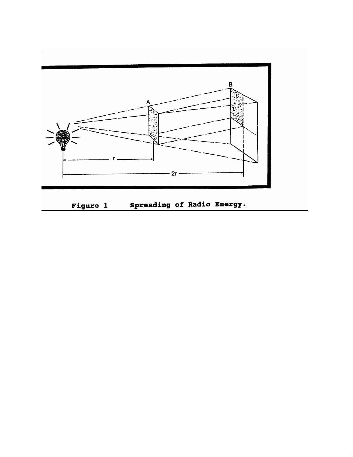
light rays, radio energy (signal) can travel from a point source outward in all directions just as a light
spreads from a light bulb. For radio waves this is called an omni-directional signal. Figure 1 shows
how radio energy (signal) decreases as distance from the source increases. Note that as the distance
(range) doubles the signal strength is reduced to one quarter of what it was (proportional to I/d
squared). Also as with light, radio signals can be focused to travel in a single direction similar to a
flashlight beam. This is called a directional signal. The shaping of the radio signal is a function of the
radios antenna system. Just as with light, radio signals can also be blocked by obstructions and bent
(diffracted) over solid obstructions. This is similar to seeing the small amount of light that can be
detected from a source behind a wall. All of these effects will be used to provide gap free tactical HF
radio communications throughout the Brigades area of operations and back to its sustaining base. It is
important to recognize that how the radio antenna shapes the signal pattern and the system operating
radio frequency(s) are the two most critical factors in assuring HF communications for the Brigade.
Page 3
Page 4

POSSIBLE TRANSMISSION PATHS WITHIN THE BRIGADE OPERATIONAL AREA: Fig
2 shows possible radio paths between two stations located in the Brigade area of operations. It is
assumed that most combat units in the Brigade will be located within a maximum distance of 400 miles
from each other for purposes of this SOP/OC. Circuits of greater distances (reach back) will be covered
under other sections of this SOP/OC. Fig 2 shows three possible low angle radio paths located along or
near the surface of the earth. These paths are called ground-wave paths because they are close to the
earth's surface or in contact with it. They consist of the (1) direct wave path. The direct wave consists
of radio frequency energy that travels through the atmosphere and near the earth directly from one
antenna to another. This is called the line of sight (LOS) mode of propagation. Maximum LOS distance
depends upon the height of the antenna above the ground and whether or not the path is obstructed by
terrain that will block radio signals. On flat ground, direct wave paths suitable for THFRS communications
can be expected out to 6-8 miles before the curve of the earth blocks the sig nals. Direct wave
communications can go much further if stations are located high on hilltops with no intervening
obstructions so control of high ground and antenna height is important when using direct wave
communications. (2) The ground reflected path like the direct path travels through the atmosphere but due
to the lower "take off' angles from the transmitting antenna, the signal energy is reflected off the earth
while traveling from the transmitting antenna to the receiving antenna. Depending upon the composition of
the ground at the reflecting point the reflected energy can be considerably reduced when it arrives at the
receiving antenna. Signals reflected off seawater lose almost no energy while signals reflected off a
sandy desert become quite weak. When summed together the direct wave and the reflected wave are
referred to as the space wave. As the two combine, they can result in either a stronger or weaker total
signal depending upon the timing difference of the two signals as they arrive. The difference in signal
phasing is caused by the longer distance traveled by reflected wave. Space wave signals will usually not
be the predominate mode of communications in the BCT. The (3) surface wave path is the transmitted
radio energy that travels along the boundary between the atmosphere and the earth's surface and is in
actual contact with the earth's surface. The surface wave is greatly affected by the electrical conductivity
of the earth in the path of propagation. With a good conductor such as seawater surface wave
communications out to 1 00+ miles are possible. With a poor surface such as sand or frozen ground
surface wave communications are greatly reduced. Surface wave signals are also greatly reduced by
heavy vegetation or mountainous terrain. Surface wave signals can be made stronger over poor ground by
using techniques that improve the conductivity of the earth near the antenna. Most HF ground-wave
communications within the BCT will utilize surface wave signals. Space wave communicatio ns will
predominate only when communicating from high ground to other high ground locations along the line of
sight (LOS). Vertical monopole (whip) man-pack and vehicle antennas of various lengths are the
antennas provided to produce the low take off angle energy needed to generate ground wave signals.
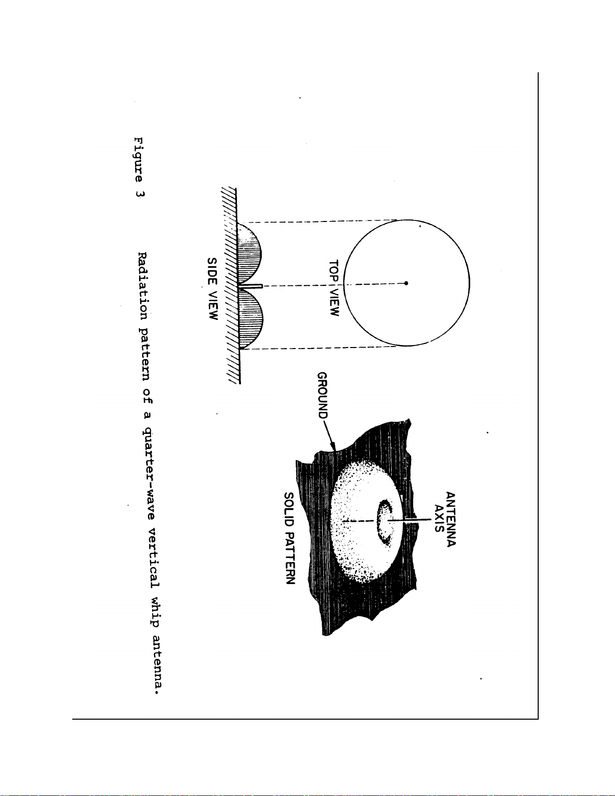
Figure 3 shows the antenna energy pattern of the vertical monopole (whip) antenna. Note that the signal
is along the surface of the earth and on the lower angles. There is much less energy on the higher angles
and none directly overhead (vertical angles). The pattern resembles a doughnut so operationally, it can be
very difficult to communicate with aircraft that are directly overhead while you can talk to aircraft many
miles away that are receiving low angle energy from a vertical antenna.
Page 5

Page 6
Page 7

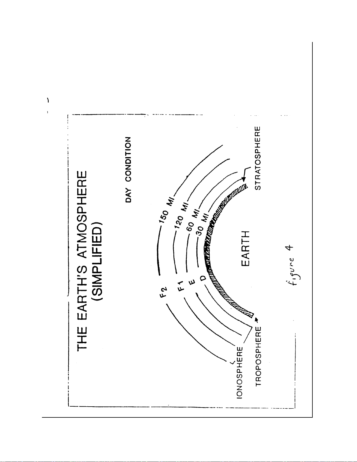
THE IONOSPHERE: The ionosphere is an electrically charged region of atmospheric gases that
surround the Earth. Ionization (electric charge) happens when solar radiation bombards atmospheric gas
molecules and for ces them to detach electrons leaving the gas molecule with a positive electrical charge
called an ion and leaving free electrons in the atmosphere. Since positive electrical charges repel each
other the gas ions tend to "bunch" in distinct "layers" of ions at heights of between 30 and 300 miles shown
in fig 4. These charged areas will reflect radio signals back to earth if they strike the ionosphere at
particular angles using particular frequency bands. Radio engineers have labeled these layers the D, E, F I
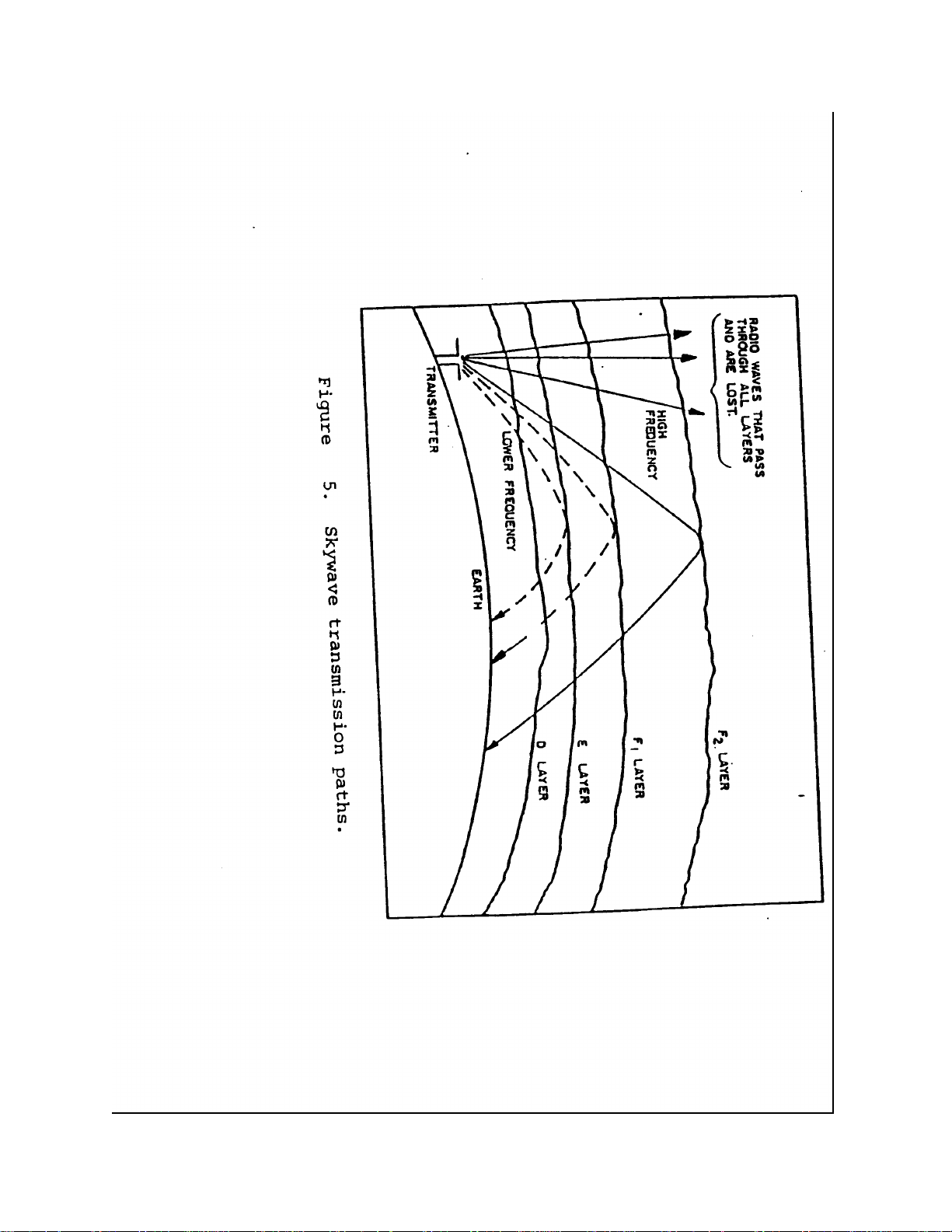
and F2 layers (see fig 4). 3 factors determine whether a radio signal will be reflected back to earth and
can be used by Brigade THFRS communications systems. They are (1) the higher the radio frequency
the more likely the signal will penetrate the io nosphere rather than be reflected by it, (2) the current ion
density determined by the amount of sun light (time of day, season, solar activity) at the time
communications is desired, and (3) the angle at which the radio wave contacts the ionosphere. See figure
5 for details. Note - that at any time of the day, year, or solar activity (sunspot) cycle there is always
available a band of radio frequencies that can be reflected off the ionosphere and will support HF
communications. The Automatic Link Establishment (ALE) feature of THFRS will find these frequencies
for the operator from the list of authorized frequencies in the radio database. Signals on these frequencies
can be used for Brigade tactical HF communications over distances of hundreds of miles unless very
unusual and rare solar activity is occurring. Also note that the angle at which the wave front contacts the
reflecting layer is determined by the radios antenna system. Low angles of radiation are produced by the
OE-5 05 and AT- IO 1 1 vertical whips and high angle radiation is produced by bending the whips into the
horizontal position with the whip tilt adaptor or by using the RF- 1 912 or RF- 1 941 wire dipole antennas
30 feet OR LESS above ground.
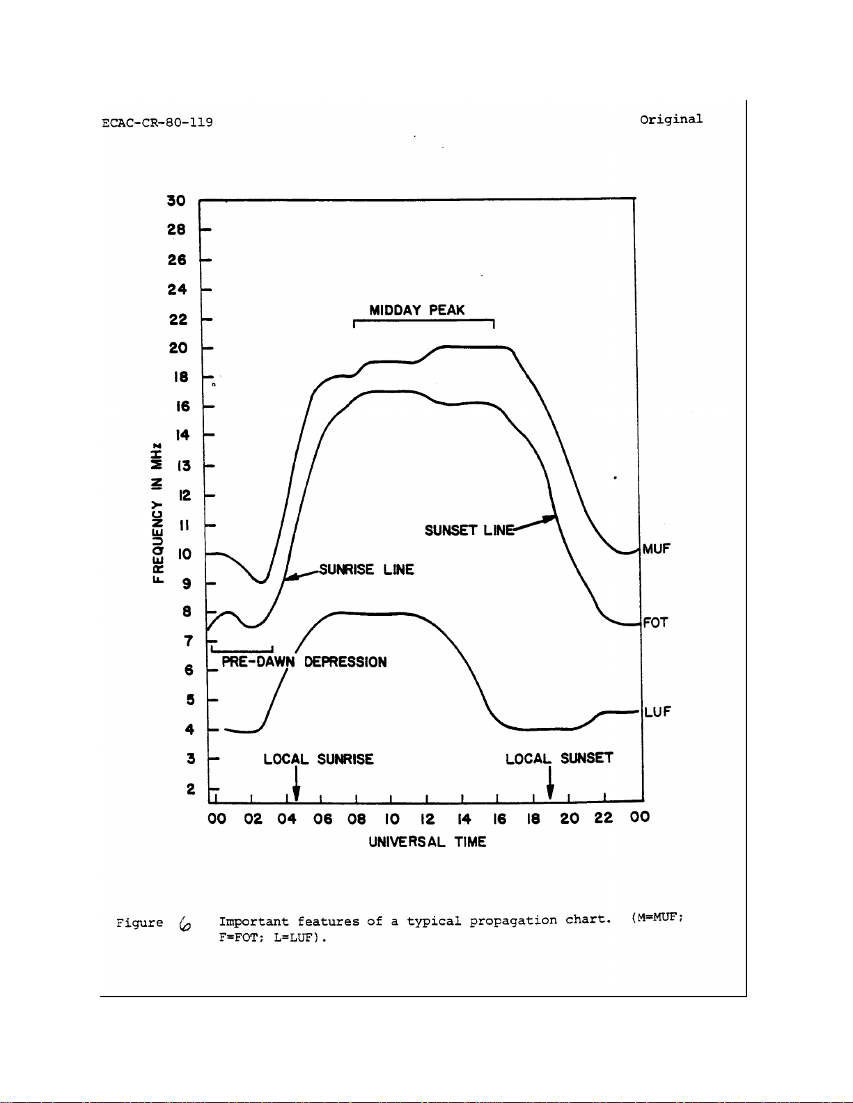
MAXIMUM USEABLE FREOUENCY (MUF)- LOWEST USEABLE FREOUENCY (LUF). '
Each layer of the ionosphere has a frequency that is the highest that the layer will reflect. The
exact frequency is determined by the amount of ions in the layer. As seen in fig 5. the lower
frequencies are reflected by the lower layers while the higher frequencies penetrate the lower
layers and are reflected back by the higher layers. To cover the largest tactical area of
operations possible the highest frequency that will reflect should be used since the higher the reflecting
layer the wider the area covered by the reflection (see fig 5.). Since the ionosphere is always changing a
general rule when in manual operation is to select a frequency 15% lower than the actual MUF to avoid
problems. This frequency is called the frequency of optimum traffic (FOT). Signals on frequencies that
exceed the MUF go through the ionosphere and are lost in outer space. The MUF is also different for
different angles of reflection. Signals on lower takeoff angles can utilize higher frequencies for
communications because they will be reflected. The ALE mode of THFRS will automatically prevent
signals with a frequency above the @ from being selected for operations. A-LE will select the best radio
frequency for communications on a continuous basis if used. A limitation of HF radio is the high radio
noise (static) level on HF frequencies. Radio noise comes from sources in outer space, lightning in the
earth's atmosphere, and man-made sources. Noise on a particular system depends mainly on locatio n and
season. For each situation there is a frequency (LUF) below which there is to
Page 8
Page 9
Page 10
Page 11

high a noise level for communications. LUF is affected by transmitter power, antenna gain and
directivity and absorption of signal by the lower layers of the ionosphere. LLTF is defined for this SOP as
the lowest frequency at which a 90% probability of communications exists. The ALE, MODEMS, and VOCODER
features of the THFRS are designed to make the LUF as low as possible by being able to operate in a high noise
environment. This widens the range of operational frequencies available for communications. A typical plot of
MUF/FOT/LUF is shown in fig.7. Note the range of frequencies between the @ and the LUF over the entire day.
Under almost every circumstance there is a range of HF radio frequencies that will be suitable for Brigade
communications. It is the responsibility of the operator and the system manager to obtain frequency assignments in
this range for operations. To aid in frequency selection sky wave and ground wave predictions and prediction
software are available through frequency management channels. It is the responsibility of the Brigade S-6 frequency
manager to predict HF radio frequency requirements, obtain authorized frequencies between the predicted @ and
LUF, and provide them to the THFRS operators and system managers. When using ALE the radio itself will test the
propagation conditions and select the best operational frequency. ALE in the BCT will be set to accomplish this
every half hour under normal operating conditions.
ANTENNAS: THE SINGLE MOST IMPORTANT FACTOR IN RELIABLE TACTICAL HF COMMUNICATIONS
IS THE ANTENNA. At HF frequencies this is especially true. In order to select the best antenna for a particular
Brigade operation, the following concepts must be understood by the THFRS operator and system manager.
Wavelength and frequency - For best radio perfon-nance, there is a specific relationship between antenna length and
operational frequency. All radio signals travel at the speed of light. The wavelength at a particular frequency is the
distance traveled by light as it completes I cycle of its motion. In order to calculate this distance (in meters) the
speed of light (in meters) has to be divided by the operational frequency in cycles per second (cps). After
simplifying the math wavelength (in meters) is equal to 300 divided by the frequency in Mega-hertz (millions of cycles
per second) As an example, the wavelength of a 3 Mhz HF signal is 300 divided by 3 (300/3) or 100 meters. This
means that in the time it takes to complete I cycle at 3 Mhz the signal has traveled I 00 meters. Knowing how to
calculate wavelength is important because signal strength depends upon the length of the antenna and the amount
of current flowing through it. For maximum current (signal) at a given frequency, the antenna needs to be !/2
wavelength or, multiples of V2 wavelength long.
Resonance - The strength of a signal radiated from an electrical conductor that has a radio frequency (RF) current
flowing depends on the length of the conductor and the amount of the current. For a given frequency, maximum
current flows and maximum signal is produced when the conductor (antenna) is !/2 wavelength long or multiples of
that length. An antenna that radiates most of the energy flowing in it is said to be resonant. At the frequencies most
used by the Brigade for fixed communications the wire antennas (AT1912, RF-1941) provided are constructed using
lengths that are close to resonance and are therefore very efficient. Mobile antenna lengths can range from less than
10 feet to as much as 32 feet. These antennas are physically to short to be resonant. In order to make the short
Page 12
Page 13

antennas radiate as strong signal as possible, antenna couplers such as the RF-382 or RF5830 are
provided. Couplers allow RF current to flow to the short antenna and dissipate energy that is not radiated
as signal but is instead, reflected back from the antenna towards the radio. The ratio of radiated power to
reflected power is called the voltage standing wave ratio (VSWR). It is important to keep this ratio low
(less than 2: 1) for highest efficiency. High VSWR will not physically damage the THFRS equipment.
Antennas whose length is close to resonance do not require couplers to function since the antenna radiates
all energy. When a coupler is needed to match an antenna it should be located as close to the antenna as
possible for best efficiency. When configured for mobile operation the coupler may be located near the
transmitter reducing the power at the antenna. This is acceptable for mobile operations or when at the
brief halt. It is Brigade policy that whenever possible more efficient ground mounted (resonant) wire
antennas will be used. Antenna couplers may also be dismounted and located at the antenna feed point to
reduce signal loss when practical. When not practical, due to operational constraints antenna couplers will
remain on the vehicle and the coupler output connected to the antenna via the cables provided even though
efficiency is reduced slightly.
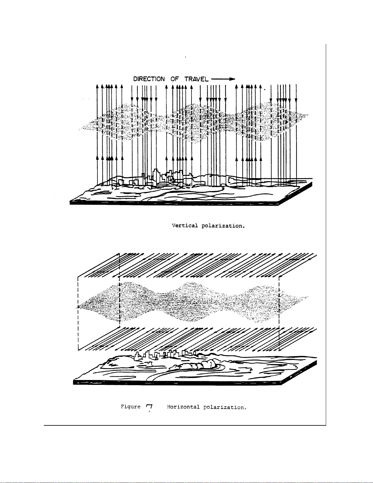
Polarization - polarization is the directional relationship of radio energy coming from an antenna to the
surface of the earth. As a rule antenna fields are vertical if the antenna is physically vertical and
horizontal if the antenna is physically horizontal. The intensity of a horizontal signal traveling in contact
with the ground (ground-wave/surface-wave) drops rapidly because in effect the electric field is shortcircuited by the earth. A vertically polarized signal does not lose strength nearly as quickly because it does
not contact the earth as much. In the Brigade, ground-wave communications will be the primary mode of
short distance (0-20miles) communications. Man-pack, ground mounted, and vehicular vertical antennas
are provided for this purpose. Horizontal antennas and adaptors that "tilt" vertical antennas into a
horizontal position are provided for long distance (0-400 miles) sky-wave communications. These
antennas provide the high take off angles necessary for beyond line of sight HF communications. All
antennas in a brigade radio net must have the same polarization. Mixing polarization of antennas in a net
as a rule will result in significant loss of signal strength due to cross polarization. S-6's will therefore
assure that all stations in a net will have the same (horizontal or vertical) antenna polarization when
possible. Surface wave communications over seawater should always use vertical polarization because
the electrical properties of seawater will greatly reduce the signal strength of a horizontally polarized
surface wave signal. Figure 7 shows the concept of vertical and horizontal polarization.
Vertical (whip) antennas. - Ground wave HF communications are most effective when using vertical
polarization over a good conductive ground. BCT man pack radios are provided the I 0-foot long OE-5 05
antenna and vehicular radios are provided the 32-foot long AT- IO 1 1 antenna. Whip antennas are most
efficient when they are between ¼ and 5/8 wavelength long at the lowest operating frequency. At HF
frequencies normally used in the Brigade the whips are far to short for efficient operation. Tuning devices
(such as the RF382 antenna coupler) are provided to electrically match a physically short or long antenna
to the radio and the transmission line. The Brigade will use the physically longest antenna possible under
the operational conditions in order to achieve best performance. For
Page 14

Example, the 10-foot OE-505 man-pack antenna can be replaced by a vertical wire tied to a support
such as a high tree branch under many conditions to improve antenna efficiency. Any good heavy wire
conductor can be used including field telephone wire or the wire from the RF- 1 941 wire dipole
antenna kit provided with the radios. The end of the vertical wire must be insulated from the support.
The feed end of the wire antenna is connected to the radio via the wire adaptor provided with the radio.
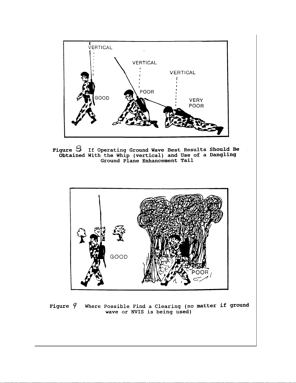
In order to further improve antenna efficiency and increase signal strength on the lower (surface wave)
radiation angles, radios in man-pack operation should be given a "tail" wire connected to the radio
ground post. The "tail" will provide a low resistance return path for antenna currents. "Tail" wires are
not provided but can be locally fabricated from computer ribbon cable, communications wire, or ground
strap braid. "Tails" should be as long as possible but not interfere with the carrying of the radio. The
man -pack "tail" concept is shown in fig 8. Along with height orientation is also very important when
operating in the man-pack configuration. The antenna must be kept as vertical as possible to produce
the best surface wave signal and also to avoid losses due to cross polarization (see Fig 8). It is also
important to operate from areas that do not have energy robbing obstructions such as trees and
buildings when possible (see fig 9). When ever possible man-packed radios should be removed from
the operators back and operated from the ground. This will reduce the capacitive coupling to ground
effects of the operators body that reduces signal strength. In addition, when the man-pack radio
(AN/PRC-150) is operated from the ground the ground stake kit should be connected to the radio
ground terminal and driven into the earth. This kit is provided with every radio and is designed to
provide a low resistance return path for ground currents. This dramatically improves signal strength and
communications efficiency. Signal strength can be improved even more by connecting "radial" wires to
the ground. Radials need to be constructed from insulated wire and connected on one end to the radio
ground terminal. Ideally, radials should be 1/4wavelength long and secured to the earth on the ends by
means of nails, stakes etc. Distribution of the radials should be symmetrical. In operational terms for
the brigade, 4 wires (more if possible) of a practical length should be crossed in the center (X) and the
center connected to radio ground. The wires should be spread by 90 degrees and secured (see fig 10).
Using ground radials improves vertical antenna performance (gain) by allowing more current to flow in
the antenna circuit and by lowering the takeoff angle of the antenna pattern. This produces an increase
in ground-wave signal strength on the low angles where it is the most useful for tactical communications
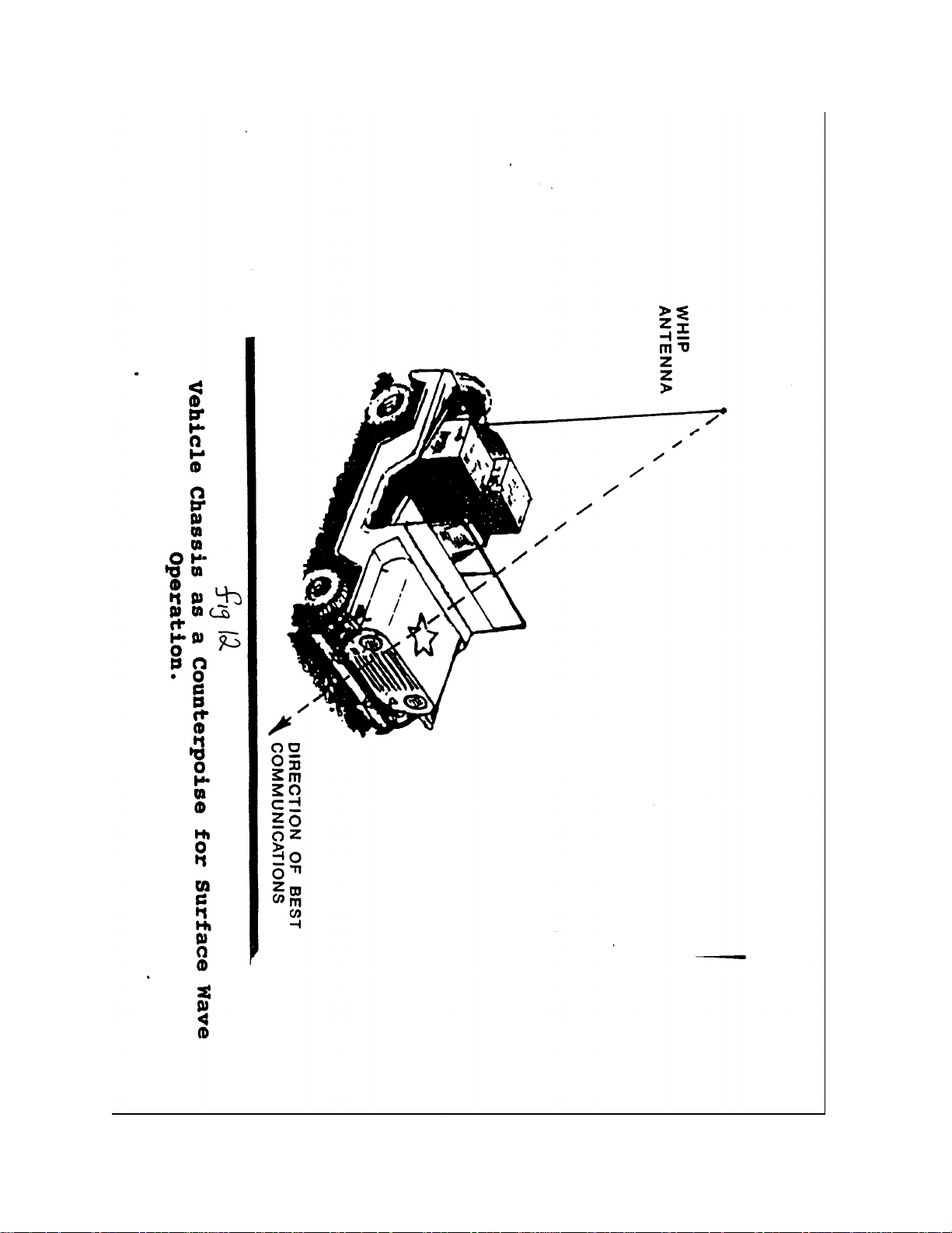
(see fig I 1). For vehicular operation both fixed and on the move the 32-foot AT-101 1 antenna is
provided. Under operational conditions it will not always be possible to use all 32 feet of this antenna
and keep it in the vertical position for best ground wave performance. The antenna should always be
kept as vertical as possible and as long as possible under the operational circumstances. The radiation
pattern for a vehicular mounted vertical whip is essentially onmi-directional however the mass of the
prime mover under the antenna will distort the antenna pattern in the direction of the vehicle mass and
provide signal gain in that direction. This can be exploited by pointing the mass of the vehicle in the
direction of the weakest station in a net or in the direction of the highest priority station in a net to
improve system operations (see fig 12).
Half-wave Doublet or Wire Dipole antenna - The THFRS provides two types of wire horizontal dipole
antennas for fixed location operations at beyond ground wave distances.
Page 15
Page 16

Page 17

Page 18
Page 19

These antennas will overcome the problems encountered when using vertical antennas in unsuitable
situations (see fig 13). The antennas provided are the RF- 1 941 light weight wire dipole and the AT- 1
912 dipole with 30 foot mast kit. The AT- 1 912 is provided only with the 400watt base station
configuration. A horizontal dipole consists of two 1/4wavelengths of wire supported at the ends and
connected to the radio in the center (see fig 14). If the antenna is kept physically 1/4wavelength or less
off the ground at the operating frequency, or laid on the ground, or at even buried under the ground the
antenna pattern produced is that of an "inverted teardrop" (see fig. 14). The bulk of the energy radiated
is on angles between 30 and 90 degrees. Since much of the radio signal is directed upward, where it
can be reflected back to earth by the ionosphere this mode of propagation was named Near Vertical
Incidence Sky wave (NVIS) mode. The relationship between antenna height above real electrical
conducting ground and signal gain is shown in fig 15. As a rule Brigade stations will try to elevate dipole
antennas to 30 feet and leave them there since the best average high angle gain is attained in the N'VIS
frequency band at this height. The NVIS frequency band is as a rule 2-4Mhz at night, and 4-8Mhz in
the day. Exception, in desert and artic areas the ground is not very conductive. This means that the
antenna may perform better if it is physically lower or even on the ground since real conducting ground
could be many feet below the surface in these areas. Dipole heights will have to be adjusted to match
actual operating conditions. The basic NVIS inverted teardrop antenna pattern remains the same for all
dipole heights 1/4wavelength or less. Only the signal strength (gain) will change. Once a radio signal on
a frequency that will be reflected is selected and the dipole is at a correct height the signal will return to
earth in an omni-directional pattern with a radius of hundreds of miles. Note dipoles can be made
directional off their broad sides by putting them close to V2wave above ground. The Brigade will NOT
normally erect dipoles this high and omni-directional communications will be used for most operations.
The NVIS signal after reflection has no holes and no "dead spots" or "skip zones" since all the energy is
coming down from above. This makes NVIS an ideal mode for Brigade size operations over wide
areas and at extended distances. Fig 16 shows the distance that can be expected by radiating signals on
all angles. Figure 14 shows strong high angle NVIS signal generated by dipoles on all angles above 45
degrees. Figure 16 shows that energy on all angles above 45 degrees will when reflected give a strong
radio signal at distances from 0 to 300 miles. This is a good match for Brigade communications needs
such as TOC to TOC and "reach-back" communications. Communications in urban areas (MOUT)
will also be made easy by using NVIS since all energy comes from above and will not be as readily
absorbed by urban structures. NVIS using ground mounted wire dipole antennas will be the most
efficient means of HF communications when stations are located at beyond line of sight (beyond
ground-wave) distances from each other.
On the move (OTM) NVIS operations - As previously described each THFRS vehicular radio is
equipped with an AT- 1011 32 foot (whip) antenna. When in the vertical position this antenna does a
good job radiating vertically polarized surface wave HF signals when on the move. The length the AT1011 (32 feet) is often too long to be practical under operational conditions. In this case, the AT-1011
should be shortened by removing antenna sections until a practical length for the operational conditions
are found. Shortening the antenna will make it less efficient for both transmitting and receiving so
operators should not make the antenna less than IO feet long under most conditions. The RF-382
antenna
Page 20

Page 21

Page 22

Page 23

Page 24

Page 25

coupler will tune a short antenna without a problem and the omni-directional antenna pattern will remain
for short antennas however signal strength will be greatly reduced when using very short vertical
antennas. This same antenna when "tipped" horizontally either forward or backward will also produce
an NVIS (dipole) antenna pattern. In order to facilitate whip antenna "tipping" the antennas are located
in a rear comer of either the IAV or shelter that they are mounted on. The antenna base is also
provided with a 7 position 6 4 whip tilt adaptor" that will allow any length of AT-1011 antenna to be
"tipped" into either the forward facing or rear facing horizontal position. When at the brief halt, the
antenna can be tipped backwards to form a classic dipole, the AT-1011 whip being one half and the
vehicle/shelter/IAV forming the other half of the dipole antenna (see fig 17). When tipped backward, a
classic "inverted teardrop" low height dipole antenna pattern is produced. If possible at the longer halts
the antenna should extended past 32 feet to by replacing it with the wire from the RF-1941 antenna kit
to make an even more efficient antenna. Ideal wire length will be V4-wave-length at the operational
frequency. When communicating on the move, the AT-1011 must be "tipped forward" over the vehicle
for operational reasons. Again, the antenna should be as long as possible for best efficiency but
practically cannot be much longer than the length of the vehicle, (usually less than 20 feet). Shortening
the antenna again makes it less efficient but in this configuration, the antenna and the vehicle form what
engineers call a transmission line antenna (see fig 18). While this antenna does not have the ideal
inverted teardrop NVIS shape that the wire dipole or rear tipped whip has, it does produce enough
energy on the near vertical angles for NVIS communications. For missions such as motorized
reconnaissance, movement to contact, convoy control, etc the bent forward whip will be the antenna of
choice for Brigade operations.
Antenna location considerations - The Brigade is a tactical fighting organization and when engaged in
combat operations will never be able to always locate its fixed and mobile radio assets at technically
ideal positions for communications operations. Brigade HF communications planners should however
attempt to comply with as many of the following citing criteria as possible in order to gain the best
technical advantage for the tactical situation.
I - Use ground radials and ground stakes under vertical antennas to improve antenna efficiency and
lower take-off angles for better ground-wave communications.
2 - Place vertical antennas on higher spots if possible to enhance ground-wave communications.
3 - Place all antennas above reasonably smooth earth if possible to reduce antenna pattern
discontinuities and distortion due to ground reflections.
4 - Avoid placing vertical antennas behind metal fencing that will shield ground-wave signals.
5 - Avoid placing vertical antennas near vertical conducting structures such as masts, light poles, trees,
and metal buildings. Antennas need to be at distances of at least one
Page 26

Page 27

wavelength or more to eliminate major pattern distortions and antenna impedance changes caused by
induced currents and reflections.
6 - Separate antennas as far as practical to reduce interference effects between radio and antenna
systems.
Remember, that wire dipoles and tipped whips on vehicles can be placed in defilade since they radiate
signals on high angles while vertical whips will have their signals greatly reduced if they are in covered
positions.
Brigade HF radio equipment - The THFRS hardware is a family of HF radio equipment based upon the
AN/PRC- 1 5 O(C) man-pack radio. By adding various power amplifiers, couplers, antennas,
software, and ancillaries to the man-pack radio various vehicular and base-station configurations can be
built. The configurations used by the Brigade are:
1 - AN/PRC- 150(C) 20-watt man-pack radio
2 – AN/PRC-104(V)1 20 watt vehicular radio using internal coupler
3 – AN/PRC-104(V)2 20 watt vehicular radio using external RF-5830 Power
Amplifier/Antenna Coupler
4 – AN/PRC-104(V)3 150-watt vehicular radio with RF-382 external Antenna Coupler.
5 - AN/TRC-210(V)2 400 watt base-station radio set.
The heart of THFRS is the 10 pound 10.5 x 3.5 x 13.2inch AN/PRC-150(C) man-pack radio (see fig
5). This radio and all ancillaries needed for man-pack operations are provided to all configurations
being built. This was done so that each THFRS user will have a "jerk and run" HF radio capability to
use in the event that they must separate from their wheeled, armored, or base-station platform. 2 BB5590, BB-590 or BB-390 standard batteries power the software controlled manpack radio. This
provides an output power level of 1, 5, or 20 watts of AM single sideband (SSB) power across the 1.6
- 30 MHz spectrum. The radio is also capable of providing 1, 5, or 10 watts of FM signal on
frequencies between 30 and 60 MHz. The waveform in this frequency range is either 16kbs wideband
FSK for data transmission or 16kbs digital voice that makes the radio interoperable with SINCGARS
in the non-hopping, encrypted or plain text digital voice mode. This mode is a very useful feature when
tactical necessity dictates the need for communications with units who have no HF communications.
Standard analog voice FM mode with VINSON COMSEC is also provided which will allow
interoperability with organizations still equipped with pre-SINCGARS tactical FM radios. This includes
many of our worldwide potential allies and our own reserve components that still have large quantities of
this type of equipment.
Page 28

The AN/PRC-150(C) is a fully software defined radio, so new features or new revis ions of existing
standards, can be added to the radio through software not hardware upgrades Integrated into the THFRS
receiver/transmitter (R/T) also known as the RT1964D(P)(C) are modes of operation and other features
that in the past required many separate hardware ancillaries and system interfaces to achieve. Embedded
THFRS operating features include:
a) automatic link establishment (ALE) - Mil-Std- 1 88-144B ALE is provided in THFRS.
ALE is capable of dealing with HF radio propagation variables in real time in order to
establish the best communications link for the current conditions. THFRS assigns each
member of an HF radio net a unique address. It also assigns each net a list of authorized
frequencies. A sounding signal is sent on each frequency authorized to a net at a
predetermined time as the radios scan the frequencies. If a sounding signal is detected
during the scanning process, a link quality analysis (LQA) is performed on the received
signal. The signal also contains the address of the transmitting station. This data is stored by
the radio. Based upon the data the radio automatically selects the best frequency for
communications at that time and the net is opened for traffic. The ALE process is repeated
periodically Individual calls (point to point), group calls (point to multipoint), and broadcasts
are all accommodated by the ALE system. ALE greatly improves the probability of
successfully establishing a useable communications system on the first try. This saves net
time and reduces channel loading. More importantly, ALE removes the guesswork from the
frequency selection process and eliminates the need for many of the hard to train frequency
management and engineering skills that past generations of HF equipment required. ALE is
a major factor in the resurgence of tactical HF radio because it eliminates the basis of many
past circuit reliability problems that were rooted in poor radio frequency selection techniques.
For more information on ALE see An-ny Communicator Spring 1994.
b) Modulators/Demodulators (MODEMS) - Radios cannot transmit or receive digital data or
digital voice information directly. Digital signals must be converted into data formats that are suitable
for transmission over narrow band (3Khz bandwidth) voice radio channels found in all tactical HF
radios including THFRS. Received signals must reverse this process. In the RT- 1 964D this is the
function of the built in MODEM(s). The RT- I 964D provides 3 basic kinds of MODEMS. They are
1) slow speed audio frequency shift keying (AFSK), 2) high-speed parallel tone, and 3) high-speed
serial (single) tone MODEMS. The high speed MODEMS are suitable for both digital voice and data
communications. Low speed MODEMS are used for data (message text) communications. A
standard low speed AFSK MODEM capable of operation at rates of 75, 150, 300, and 600 bits per
second (bps) is provided. This type of signaling is standard in virtually every HF data system built
worldwide over the last 40 years. At this time THFRS will use this mode when communicating
with older radios still in use in the US forces (e.g. the AN/GRC- 1 93) or with older HF radioteletype sets used by our allies. FSK signaling along with analog voice signaling is the "common
denominator" present in almost every HF radio in the world so it remains useful particularly in
coalition warfare. A high-speed parallel tone type MODEM is also embedded in the THFRS.
This MODEM produces 39 sub-carrier audio tones that fit within the 3 kHz wide radio audio
channels. A process called Quadrature Differential Phase Shift Keying (QDPSK), which simply
means that the data is represented as a shift in the phasing of an audio tone that can take 4
(quadrature) possible states, modulates each of these tones. These phase shifts are then
Page 29

distributed, interleaved, and synchronized over 39 sub-carrier tones contained in the narrow band
(voice) channel. This type modulation is excellent for recovering signals that have been sent over a
radio path that is subject to multi-path and signal fading effects because all tones will not fade at the
same time. If the data is coded and spread over all the sub-carrier tones the signal processing
techniques produce performance that is many times better than the same radio circuit using older
FSK modulation. The THFRS 39-tone MODEM provides data rates between 75 and 2400 bps.
In recent years the third type MODEM provided by THFRS called the serial or single tone
MODEM has eclipsed the use of the 39-tone MODEM. Serial tone MODEMS are easier to
build and perform better than parallel tone MODEMS under most conditions. Serial tone will be
the most widely used data mode in THFRS. THFRS will normally use the 39-tone waveform only
when communicating with other systems that have only a 3 9-tone capability. The Mil-Std-188110B serial tone MODEM embedded in THFRS uses phase shift keying (PSK) on a single carrier
frequency to represent data. Many small shifts in phase can be created to represent various binary
states. The addition of amplitude shifts to the phase shift information can also be used to increase
the amount of information contained during any time interval. The serial tone MODEM in THFRS
can be used at data rates of 75 to 9600 bps depending upon path conditions. In addition to US
standard serial tone MODEM capabilities NATO STANAG 4285 (75-2400bps) serial data mode
and STANAG 4415 (75bps) robust serial data mode used when severely degraded circuit
conditions exist are provided to enhance operations with equipment built to NATO standards.
c) Electronic Counter-Counter Measures (ECCM) - THFRS provides a robust frequency
hopping waveform for use with serial tone data (75-2400bps) and digital voice (600 or 2400 bps) to
reduce the effects of interfering signals or intentional jamming by an enemy. This capability also
lowers the probability of intercept and detection (LPI/LPD) by hostile forces.
d) Voice communications - Both analog and digital voice modes of communications are provided.
In digital mode voice signals are converted into digital representations and coded to correct errors
(VOCODER). The digital voice representations are then transmitted by the serial tone MODEM
at rates of 2400 bps for clear channel operation or at a slower rate of 600 bps for better
performance over degraded channels. 600 bps digital voice can provide effective voice
communications in environments where signal strength and noise are actually equal.
e) Cipher modes - THFRS has embedded NSA certified US Type -1 encryption capability.
Standard KY-99, KY- I 00, KG-84C, and KY-57 modes are provided for interoperability with
compatible systems. Also embedded in the AN/PRC- I 50(C) is the internationally used
CITADEL encryption system useful for coalition operations.
f) COMSEC key management and fill - THFRS will accept COMSEC keys from a variety of
COMSEC load devices such as the KYK- 1 3, KOI- 1 8, KYX- 1 5, and AN/CYZ- I 0 via the
standard fill connector located on the front panel. Unique to THFRS is the COMSEC ignition key
(CIK) which is contained in the radios removable Keypad/Display Unit (KDU). By removing the
KDU the COMSEC is rendered inert. The KDU can be easily removed, safely stored, and
Page 30

reinstalled. This removes the need to remove and reload COMSEC every time the radio is left
unattended.
g) Transparent Internet Protocols (IP) - In anticipation of the Army's transformation to an IP
based architecture for the Army Battle Command System (ABCS), THFRS has provided internally
the necessary connectors and Internet protocols. This will allow seamless integration and direct
connections with devices such as commercial and military PC
workstations, laptops, routers, servers, etc without the need for additional external hardware and
software "gateways".
h) System management - THFRS includes not only the radio hardware but
also the means to manage/select the various features and modes of radio operation without
having to enter data via the radio KDU. Every S-6 section in organizations deploying
THFRS will also receive an army Common Hardware System (CHS) laptop computer with
radio programming application (RPA) software. The RPA software has a user friendly
Microsoft Windows "look and feel" and will allow the Operators to define and configure
radio nets, assign ALE addresses, select presets for MODEMS, store communications plans
etc. Information can then be transferred to individual radios via a data transfer cable to the
front panel radio data connector. This capability greatly reduces operator stress and errors
in data entry when compared to using the KDU as the means of setting up the radio. KDU
data entry remains available if needed.
Radio Programming Application - Two methods of entering system required data into the THFRS
radio are provided. They are data entry through the Keyboard Display Unit KDU on the radio front
panel or through the use of a laptop computer and Radio Programming Application (RPA) software.
The RPA software will run on any laptop computer platform that provides a speed of 200 Mhz, a
minimum 64Mb of memory (Ram), and the Windows 98, Windows 2000, or Windows NT operating
system. RPA will install itself on any hardware with this capability. Once installed operators need
only enter planning information such as authorized radio frequencies, radio configuration data, ALE
information, radio presets, frequency hopping information etc into the RPA and the RPA will configure
the radio hardware through the radio data port. RPA can be used to reprogram the radios with
modified parameters as required. Multiple sets of system information can be stored as separate plans
for contingency operations. The Brigade S-6 will select the number of plans to be stored in the RPA
at each echelon based upon the Brigades operational planning. Once created, plans can be
transported by floppy disk media, transmitted over the air, or printed. RPA generated information will
be used as the HF input data to the Brigade SOI.
The basic programming procedures for the THFRS hardware and radio programming application
(RPA) are shown below. Operators will note that since the THFRS is a software based/software
programmable radio there are many operator-selected options. Please refer to the proper equipment
manuals for a more detailed explanation of what these options are and when to use them. Items in
BOLD print indicate a default value. Default values have been selected that will achieve a high level
of system operation and reliability under the most common conditions that the Brigade will encounter.
Page 31

Under unusual circumstances, the operator may be required to change a particular value from the
default value in order to improve system perfon-nance under a particular operational condition.
Changes from default values should only be made by direction of the unit S-6. Operators will also be
required to enter standard information such as frequency and address data into the radio in order to
operate. Operators need to pay careful attention when entering data and to double-check themselves
frequently to avoid errors. Since this equipment is digital and software controlled errors in data entry
may result in the failure of the system to operate properly.
IT CANNOT BE STRESSED TOO OFTEN THAT ANTENNA AND FREOUENCY ARE
THE TWO MOST CRITICAL FACTORS IN MAKING HF COMMUNICATIONS
WORK FOR THE BRIGADE. PROPER SELECTION OF ANTENNAS FOR LOS OR
BLOS MODES COUPLED WITH SELECTION OF FREOUENCIES THAT WILL
EXTEND GROUNDWAVE DISTANCE OR BE REFLECTED OFF THE IONISPHERE
AS APPROPRIATE ARE ESSENTIAL.
Page 32

AN/PRC-150(C) HF Manpack Radio
Includes:
*ON672486-010 Radio Chassis Assy., RT-1694D(P)(C)/U
*10075-1399 Handset
*10303-1008-01 Ground Stake Kit
*10372-0240-01 OE-505 Whip Antenna
*10372-1230 Y-Adapter Cable Assy.
*10511-0704-012 Cable Assy., KDU
*10513-4800-02 Battery Box
*l05l5-0103-4100 Operator Manual
*10535-0775-AOO6 Cable, Assy., Remote, PPP (Data)
*RF-3016-03 CW Key
Page 33

BASIC PROGRAMMING PROCEDURES
PURPOSE. This is a sequential guide and items should be programmed in the order presented as they apply to the
operational scenario. While navigating through the radio menu structure, the Left/Right arrow keys on the KDU
keypad are used to select the item to be programmed, and the Up/Down arrow keys are used to scroll through the
available parameters for each item. Default settings on a zeroized radio for each item are shown in bold where
applicable.
NOTE: Press ENT (Enter) after each step or change to save programmed features.
GENERAL RADIO PROGRAMMING
COMSEC PROGRAMMING (CITADELKEYS PROGRAMMING) I . ENTERING A NEW KEY
a. Press PGM
b. Select COMSEC
c. Select CITADEL
d. Select KEYS
e. Select ENTER
f Key Type (R-F-5800, RF-5022/PRC-138)
g. Enter Key Name (Can be up to 4 alphanumeric characters long) or leave as default.
h. Use alphanumeric keys to enter 32 character key
i. Load AVS Key (NO, YES) If yes enter 12 number key.
2. UPDATE EXISTING KEY
a. Press PGM
b. Select COMSEC
c. Select KEYS
d. Select UPDATE
e. Use Up/Down arrows to select correct key to be updated f Select YES to update
3. ERASE EXISTING KEY
a. Press PGM
b. Select COMSEC
c. Select KEYS
d. Select ERASE
e. Use Up/Down arrows to select correct key to be erased
f. Select YES to erase
4. CRYPTO MESSAGE INDICATOR
a. Press PGM
b. Select COMSEC
c. Select MI (Used to lengthen the crypto sync time manually. Default setting the length is selected
automatically by the radio - recommended)
d. Crypto MI (DEFAULT, I X, 3X)
NOTE: U.S. ARMY UNITS WILL NOT NORMALLY USE CITADEL CRYPTO UNLESS
OPERATING WITH ALLIED FORCES ONLY EOUIPPED WITH THIS SYSTEM. CITADEL IS NOT APPROVED
BY THE NSA AS A COMSEC SYSTEM. CITADEL WILL NEVER BE USED WITHIN THE BRIGADE FOR
OPERATIONS.
Page 34

COMSEC PROGRAMMING (TYPE I KEYS PROGRAMMIN@
! NOTE: Unlike CITADEL, Type I Encryption keys are loaded with a U.S. COMSEC loader (e.g. KYK-13, KOI -18,
CYZ-10A). The loaded keys are assigned to selected channels during the System Presets. Refer to the END of this
guide for brief instructions on COMSEC loading.
1 . ERASE EXISTING KEY
a. Press PGM
b. Select COMSEC
c. Select TYPE I
d. Select KEYS
e. Select ENTER
f. Use Up/Down arrows to select correct Crypto type to erase.
g. Use Right/Left arrows to tab to Crypto key then use Up/Down arrows to select key to erase.
h. Select YES to erase
2. VIEW SPECIAL KEYS
a. Press PGM
b. Select COMSEC
c. Select TYPE I
d. Select KEYS
e. Select SPECIAL
f. Use Up/Down arrows to view status of SPECIAL keys
COMSEC CONFIG PROGRAMMING (TYPE I)
1 . CONFIGURE TYPE I KEY PARAMETERS
a. Press PGM
b. Select COMSEC
c. Select TYPE I
d. Select CONFIG
e. Select ENTER
f Select ALL.
g. Select ENTER
h. PT Beeps (ENABLED, DISABLED)
2. CONFIGURE TYPE I ANDVT-BD PARAMETERS
a. Press PGM
b. Select COMSEC
c. Select TYPE I
d. Select CONFIG
Page 35

e. Select ENTER
f Select ANDVT-BD.
g. Select PREAM (STAND, ENHAN)
h. Select TRN SEQ (6,9,12,15,30,60)
PROGRAM RADIO SETTINGS
1. Press PGM
2. Select CONFIG
3. Select RADIO
a. Transmit Power (HIGH, MEDIUM, LOW) use lowest power possible to save battery and
improve EW characteristics
b. BFO (0Hz,-40OOHz to +40OOHz in 10Hz Steps)
Page 36

c. Squelch (OFF, ON) use squelch when signals are strong to cut off audio noise when receivi ng
d. Squelch Level (HIGH, MEDIUM, LOW) adjust as appropriate. Higher levels require strong receive
signal/audio levels. CAUTION: weak signals may be lost if squelch level is to high.
e. FM Squelch Type (NOISE, TONE ) use noise squelch when operating with equipment that has no tone
capability.
Radio Silence (OFF, ON) use radio silence when directed. Will not allow radio to transmit in any mode.
g. Internal Coupler (ENABLED, BYPASSED) use bypass when using RF-382 or RF-5830 external couplers.
h. FM Deviation (8.0kHz, 6.5kHz, 5.OkHz)
i. CW Offset (0Hz, 1000Hz)
j. Rx Noise Blanking (OFF, ON) use only when in a high receive noise envirom-nent.
k. Compression (OFF, ON)
1. 2OW AMP Coupler (MEMORY TUNE , LEARN TUNE, DISABLED)
m. Radio Self ID (001 - 254) obtai n from unit SOI
n. Error Beeps (OFF, ON)
PROGRAM DATA PORT SETTINGS
1. Press PGM
2. Select CONFIG
3. Select PORTS
4. Select DATA
a. Data Rate (19.2 Kbps to 75 bps) 2400 bps Use higher data
rate on clear channels with strong receive signals. Slow data rate to improve operations under poor, high noise,
low signal strength conditions. Rates to change on order of the S-6.
h. Data Bits (8, 7)
c. Stop Bits (1, 2)
d. Parity (NONE , ODD, EVEN, MARK, SPACE)
e. Flow Control (NONE , XON/XOFF, HARDWARE)
f. Echo (ON, OFF)
g. Level (RS232, MIL - 1 88)
h. TX Clock Source (INTERNAL, EXTERNAL, RECOVERED)
i. Key line (RTS.AUX-AUDIO)
MESSAGE (ROUTING INCOMING DATA)
1. Press PGM
2. Select CONFIG
3. Select MESSAGE
a. Route Modem Data To (DTE PORT, RDP, FILE)
h. Route ARQ Data To (DTE PORT, RDP, FILE)
AUXILIARY AUDIO PROGRAMMING
I . Press PGM
2. Select CONFIG
3. Select AUDIO
a. Aux (MUTE, UNMUTE )
h. Sidetone Audio (MUTE, UNMUTE )
SET RADIO TIME OF DAY (TOD) See SOI and OPORD for formats and procedures. Brigade will normally use 24hour clock and ZULU time.
Page 37

1. Press PGM
2. Select CONFIG
Page 38

3. Select TOD
a. LJTC Offset (Use Up/Down keys to select or "-" offset then use numeric keys to select correct offset
value)
b. Time Format (I 2-HR, 24-HR)
c. New TOD (Press numeric keys to enter TOD)
d. Date Format (MM-DD-YY, DD-MM-YY, YYYY-MM-DD, ZULU)
e. New Date (Press numeric keys to enter new date)
LPC (NOISE CANCELLATION) PROGRAMMING
1. Press PGM
2. Select CONFIG
3. Select
4. Select LPC
- Noise Cancellation (ON, OFF) Use LPC noise cancellation when operating in a high noise environment.
OPTIONS (PREPOST CONFIGURATION) External pre/post selectors are provided with the AN/VRC- I 04(V)3 150w
vehicular set and the AN/TRC-2 I O(V)2 400w base -station set to reduce interference. Always select this option.
I . Press PGM
2. Select CONFIG
3. Select -+
4. Select OPTIONS
a. EXT POST SELECTOR (ENABLED, DISABLED)
h. EXT Preselector (ENABLED, DISABLED)
c. EXT RX Filters (ENABLE DURING SCAN, DISABLE DURING SCAN)
d. EXT Scan Rate (FORCE SLOW SCAN , USE ALE SCAN RATE)
e. Prepost Antenna (SINGLE RX/TX, SEPARATE RX/TX)
CHANNEL PROGRAMMING
I . Press PGM
2. Select MODE
3. Select PRESET
4. Select CEIANNEL
a. Enter desired channel number (000- 1 99) see unit SOI
h. Enter desired RX FREQUENCY see unit SOI
c. Enter desired TX FREQUENCY, or press ENTER
d. Modulation (USB, AME, CW, FM, LSB) see unit SOI
e. AGC Speed (SLOW, MED, FAST, DATA, OFF) select for conditions. Use to obtain steady receive signal
level.
f IF Bandwidth NOTE: Options are dependent on modulation type selected.
- USB or LSB (2.0 kHz, 2.4 kHz, 2.7 kHz, 3.0 kHz) Use narrow bandwidth to reduce
noise and interference on order of the S-6.
- AME (3.0 kHz Only)
- CW (0.5 kHz, 0.35 kHz, 1.0 kHz, 1.5 kHz)
g. RX Only (YES, NO)
h. Enable Hail TX NOTE: Not available for channel 000 (YES, NO)
i. Max TX Power (00000 WATTS this is default, for maximum transmit power). Use to limit power and save
battery life.
See SOI or OPLAN for power limits
j. Enable SSB Scan (YES, NO) NOTE: Selecting yes automatically places current channel in scan list.
5. Repeat step 4 for the remaining channels to be programmed.
MODEM PROGRAMMING
1. Press PRGM
Page 39

2. Select MODE
3. Select PRESET
4. Select MODEM (Different modem types have different options available, please consult the radio operations
manual for a detailed explanation of settings):
a. Select the modem preset name you wish to modify. Note: In a zeroized radio, modem presets are given
default names MDML to MDM20.
b. Enter desired name up to 15 characters (e.g. 24SERIAL)
c. Select MODEM TYPE (e.g. SERIAL)
d. Select DATA RATE (e.g. 2400)
e. Select INTERLEAVE: (e.g. SHORT)
f. Select MODE: ASYNC (or SYNCHRONOUS, as required)
g. Select DATA BITS: 8
h. Select STOP BITS: 1
i. Select PARITY: NONE
j. Select ENABLE?: YES
5. To program the next modem preset, press Up arrow, select modem preset name and repeat steps a - j. For
Brigade operations all nets will use the SERIAL MODEM at the highest data rate and shortest interleave
possible for the conditions. Changes will be made on order of the S-6. Use of other MODEMS will only occur
when operating with other forces not equipped with serial tone MODEMS.
AUTOMATIC LINK ESTABLISHMENT PROGRAMMING See SOI/OPLAN for programming data.
1 . CHANNEL GROUP PROGRAMMING
a. Press PGM
b. Select MODE
c. Select ALE
d. Select CHAN GROUP
e. Select ADD CHANNEL GROUP
f Enter desired CHANNEL GROUP NUMBER
g. Select ADD CHANNEL
h. Enter desired CHANNELS for channel group
i. To modify, review, or delete channel groups, at step e select REVIEW or DELETE then use the Up/Down
arrow keys to view options for each selection.
2. SELF ADDRESS PROGRAMMING
a. Press PGM
h. Select MODE
c. Select ALE
d. Select ADDRESS
e. Select SELF
f Select ADD! NOTE: You must enter a 3 character Self Address or ALE will not function. Example: 123
must be entered first then any address containing from 1-15 characters, numbers or a combination can
be entered.
g. Enter your own SELF ADDRESS (e.g. RAD1).
h. Enter CHANNEL GROUP to associate with this address
i. To review or delete Self Addresses, at step f select REVIEW or DELETE. See unit SOI for self-address and
channel group input data.
3. INDIVIDUAL ADDRESS PROGRAMMING
a. Press PGM
b. Select MODE
c. Select ALE
d. Select ADDRESS
e. Select INDIVIDUAL by pressing Up arrow
Page 40

f. Select ADD
g. Enter an INDIVIDUAL ADDRESS (e.g. @2).
h. Enter CHANNEL GROUP to associate with this address
i. Select correct ASSOCIATED SELF (e.g. RT I) by pressing Up cursor.
j. Repeat (e - i) for remaining INDIVIDUAL ADDRESS(es).
k. To review or delete Individual Addresses, at step f, select REVIEW or DELETE.
4. NET ADDRESS PROGRAMMING
a. Press PGM
h. Select MODE
c. Select ALE
d. Select ADDRESS
e. Select NET by pressing Up arrow
f Select ADD
g. Enter an NET ADDRESS (e.g. RTO)
h. Enter CHANNEL GROUP to associate with this address
i. Select appropriate ASSOCIATED SELF (e.g. RAD I)
j. ADD NET MEMBERS (Ensure all net members are programmed in the same order on all radios used)
k. To review or delete Net Addresses, at step f, select REVIEW or DELETE.
5. ALE CONFIGURATION PROGRAMMING
a. Press PGM
b. Select MODE
c. Select ALE
d. Select CONFIG
e. Max Scan Channels Note: This is a critical parameter. It must be set to the number of channels that have
been programmed into the channel group to be scanned
f. Listen Before TX (OFF, ON)
g. Key To Call (OFF, ON)
h. Max System Tune Time Note: This is a critical parameter. It must be set to the worstcase tune time for
any radio in the network. If time is unknown start with 20 seconds as system tune time.
i. Link Timeout (OFF, ON)
j. Link To Any Calls (OFF, ON) when a station transmits the address ANY, any ALEcapable radio that
receives the transmission will stop scanning and automatically respond to the call.
k. Link To All Calls (OFF, ON) when a station transmits the address ALL, any ALE-capable radio will stop
scanning, but will not respond (transmit).
1. AMD Operation (ENABLED, DISABLED)
m. AMD Auto Display (ENABLED, DISABLED)
n. Scan Rate (ASYNC, 2, 5)
6. LQA EXCHANGE PROGRAMMING
a. Press PGM
b. Select MODE
c. Select ALE
d. Select LQA type (EXCHANGE, SOUND)
e. Select ADD
Select INDIVIDUAL or NET as desired
Page 41

g. Select desired addresses)
h. Select the desired START TIME
i. Select the desired REPEAT INTERVAL Under normal operating conditions LQA interval will be every 30
minutes. Changes will be on order of the S-6
Page 42

7. LQA SOUND PROGRAMMING
a. Press PGM
b. Select MODE
c. Select ALE
d. Select LQA
e. Select LQA type (EXCHANGE, SOUND)
f Select ADD
g. Select SELF ADDRESS to be used
j. Select the desired START TIME
k. Select the desired REPEAT INTERVAL
8. AMD CREATE (TX MSG)
a. Press PGM
b. Select MODE
c. Select ALE
d. Select AMD
e. Select TX-MSG
Select TX-MSG (EDIT, REVIEW, DELETE)
g. Press ENTER twice
h. Enter message using KEYPAD
i. Press ENTER to save
j. Press CLR to escape
9. AMD REVIEW/DELETE (RX MSG)
a. Press PGM
b. Select MODE
c. Select ALE
d. Select AMD
e. Select RX-MSG
f Select RX - MSG (REVIEW, DELETE, COPY)
g. Press ENTER
HOP PROGRAMMING NARROW BAND/WIDEBAND/LIST HOPPING
1 NARROWBAND HOP PROGRAMMING
a. Press PGM
b. Select MODE
c. Select HOP
d. Select CHANNEL
e. Select ADD
f Enter channel to be added (must be in the range 00- 1 9)
g. Hop Type, select (NARROW, WIDE, LIST)
h. Enter CENTER FREQ in MHz
i. Press numeric keys to enter a 1 - 8 digit HOP CHANNEL ID
j. Press alphanumeric keys to enter up to 8 character TOD MASK
k. Auto respond (YES, NO)
2. WIDEBAND HOP PROGRAMMING
a. Press PGM
b. Select MODE
c. Select HOP
d. Select CHANNEL
e. Select ADD
f. Enter channel to be added (must be in the range 00-19)
Page 43

g. Hop Type, select WIDE
h. Press numeric keys to enter LOWER FR.EQ'in MHz
i. Press numeric keys to enter UPPER FREQ in MHz
j. Press numeric keys to enter a I - 8 digit HOP CHANNEL ID
k. Press alphanumeric keys to enter up to 8 character TOD MASK
1. Auto respond (YES, NO)
3. LIST HOP PROGRAMMING
a. Press PGM
h. Select MODE
C. Select HOP
d. Select CHANNEL
e. Select ADD
f Enter channel to be added (must be in the range 00- 1 9)
g. Hop Type, select LIST
h. Select ADD List Members
i. Press numeric keys to enter frequencies in MHz. Must enter 5 frequencies minimum,
50 frequencies maximum between 2 and 29.000MHz.
Press CLR to exit Add Freq List menu.
k. Select NO to exit Add List Members menu
1. Press numeric keys for 1 - 8 digit HOP CHANNEL ID
M. Press alphanumeric keys to enter up to 8 character TOD MASK
n. Auto respond (YES, NO)
4. HOP EXCLUSION BAND PROGRAMMING
a. Press PGM
b. Select MODE
c. Select HOP
d. Select EXCLUDE
e. Select ADD Exclude Band
Press numeric keys to enter the Exclude Band Number from 0 - 9
g. Press numeric keys to enter the Lower Freq
h. Press numeric keys to enter the Upper Freq
5. HOP CONFIGURATION PROGRAMMING
a. Press PGM
b. Select MODE
c. Select HOP
d. Select CONFIG Use the Up/Down arrow keys to view available selections (shown in parenthesis with the
default in bold) for each of the following:
Manual Sync (YES, NO)
- Hail RX (YES, NO)
SYSTEM PRESET PROGRAMMING
1 . FIX MODE SYSTEM PRESET
a. Press PGM
h. Select MODE
c. Select PRESET
d. Select SYSTEM
e. System Preset To Change (On a zeroized radio, system presets are given default names of SYSPREI to
SYSPRE75) Use the Up/Down arrow keys to select the preset to chan,--,,@
Preset Name (Press the alphanumeric keys to enter a name up to 9 characters in length)
g. Radio Mode (Select FIX)
Page 44

h. Channel Number (Enter the channel number to associate with the preset)
i. Modem Preset (OFF or use the Up/Down arrow keys to enter a preconfigured Modem preset)
j. Select Encryption TYPE (TYPE I, CITADEL, NONE)
k. Select Crypto MODE (e.g. KG -84R)
1. Select Encryption KEY (e.g. TEKO I)
m. Select PT VOICE MODE (CLR, CVSD, AVS, DV6, DV24)
n. Select CC/CT VOICE MODE (DV24, NONE, DV6)
o. Select ENABLE (YES, NO)
2. HOP MODE SYSTEM PRESET
a. Press PGM
b. Select MODE
c. Select PRESET
d. Select SYSTEM
e. System Preset To Change (On a zeroized radio, system presets are given default names of SYSPREI to
SYSPRE75) Use the Up/Down arrow keys to select the preset to change
f. Preset Name (Press the alphanumeric keys to enter a name up to 9 characters in length)
g. Radio Mode (Select HOP)
h. HOP Channel (Select HOP Channel to associate with this preset)
i. Modem Preset (OFF or use the Up/Down arrow keys to enter a preconfigured Modem preset)
j. Select Encryption TYPE (TYPE I, CITADEL, NONE)
k. Select Crypto MODE (e.g. KG -84R)
1. Select Encryption KEY (e.g. TEKOI)
m. Select PT VOICE MODE (CLR, DV6)
n. Select CC/CT VOICE MODE (DV6)
o. Select ENABLE (YES, NO)
3. ALE MODE SYSTEM PRESET
a. Press PGM
h. Select MODE
c. Select PRESET
d. Select SYSTEM
e. System Preset To Change (On a zeroized radio, system presets are given default names of SYSPRF,L to
SYSPRE75) Use the Up/Down arrow keys to select the preset to change
Preset Name (Press the alphanumeric keys to enter a name up to 9 characters in length)
g. Radio Mode (Select ALE)
h. Associated Self (Select Self Address to associate with this preset)
i. Modem Preset (OFF or use the Up/Down arrow keys to enter a preconfigured Modem preset)
j. Select Encryption TYPE (TYPE I, CITADEL, NONE)
k. Select Crypto MODE (e.g. KG -84R)
1. Select Encryption KEY (e.g. TEK01)
m. Select PT VOICE MODE (CLR, AVS, DV6, DV24)
n. Select CC/CT VOICE MODE (DV24, NONE, DV6)
o. Select ENABLE (YES, NO)
Page 45

RADIO OPERATIONS
SELECTING RADIO MODE
1. FIX MODE Press MODE (#3) button on KDU until FIX is displayed and press ENT or wait and the
radio will automatically enter FIX mode.
2. ALE MODE Press MODE (#3) button on KDU until ALE is displayed and press ENT or wait and
the radio will automatically enter ALE mode.
3. HOP MODE Press MODE (#3) button on KDU until HOP is displayed and press ENT or wait and
the radio will automatically enter HOP mode.
PLAIN/CIPHER TEXT (PT/CC/CT) OPERATION ROTATE fimction switch to desired position.
SETTING RADIO OPTIONS The Option menu is selected by pressing the OPT button on the KDU
while in FIX, A-LE, or HOP mode. The Option menu is mode specific. The following options
are common to all modes of operation.
I . GPS-TOD N/A.
2. RETLTNE when selected will retune currently selected channel. Will not retune while scanning.
3. RADIO OPTIONS Options are global and affect the entire range of channels and presets in
use.
a. Press OPT
b. Select RADIO
c. TX Power (LOW, MED, HIGH)
d. BFO (+/- 4kHz in IO Hz steps)
e. Squelch Level (LOW, MED, HIGH)
f. FM Squelch Type (TONE, NOISE)
g. Radio Silence (ON, OFF)
h. Internal Coupler (ENABLED, BYPASSED)
i. RX Noise Blanking (OFF, ON)
j. Radio Self ID
4. SCAN OPTIONS
a. Press OPT
b. Select SCAN
c. Enable SSB scan (NO, YES)
5. TEST multiple tests can be performed without test equipment by using this feature. Refer to the
operator's manual for a detailed description of each test available.
NOTE: The following options are mode specific and are only available if the feature is
installed in the radio and it is the current operating mode.
6. ALE OPTIONS
a. Press OPT
Page 46

h. Select AJE
c. Select LQA
d. EXCH or SOUND Use EXCHANGE to perform a two -way link analysis between your
radio and another radio or group of radios on all pre-programmed frequencies. Use
SOUND as a passive, one-way transmission, from your radio to another radio or
group of radios.
e. Scores select an individual or net name and scroll through the channels and available scores.
f. TX-MSG Used to transmit pre-entered AMD messages.
9- RX-MSG Used to review received AMD messages.
2. HOP OPTIONS, Same as ALE options
ALE OPERATIONS
1. ALE Scan Operation
a. Radio will begin scanning when ALE mode is selected.
b. To stop scanning press CLR. To resume scanning press CLR again.
2. Placing an ALE call.
a. Press CALL key
b. Select CALL TYPE (MANUAL or AUTOMATIC) Manual call allows you to
select a specific channel to call on and automatic will start calling on the channel with the highest LQA
score.
C. Select ADDRESS TYPE (INDIVIDUAL, NET, ANY, ALL)
3. Terminating an ALE Link. To terminate an ALE link press CLR button. The radio will display
"TERMINATE LINK". Scroll to YES and press ENT.
HOP OPERATIONS
1. HOP Operation
a. Press MODE button to select HOP.
b. Press PRE button to select desired HOP preset.
2. Manual Sync.
C. Press CALL key
d. Manual SYNC type (REQUEST, BROADCAST)
NOTE: The easiest form of sync is broadcast. Only I station in the net should perform the broadcast,
which will sync the entire listening stations. If your st ation does not receive a sync, you must send a Sync
Request by selecting REQUEST and pressing ENT.
COMSEC LOADING CYZ10
1. PRESS ON TO ACTIVATE CYZIO (ANCD)
2. PRESS MAIN MENU KEY UNTIL RADIO IS OBSERVED
3. PRESS LTR LOCK TO OFF AND PRESS ARROW KEY TO SELECT RADIO THEN
ENTER
4. SELECT COMSEC THEN N <ENTER>
5. SELECT LD THEN <ENTER>
6. SELECT TEK THEN <ENTER>
7. USE PG UP TO SELECT KEY AND THEN <ENTER>
8. CHOOSE QUIT THEN <ENTER>
Page 47

9. CONNECT CYZIO TO RADIO (Jl8) THEN PRESS DOWN ARROW KEY
10. TURN MODE SWITC H TO LD ON RADIO
I 1. SELECT FILL DEVICE - KYK-13 THEN <ENTER>
12. SELECT CRYPTO TYPES AND PRESS <ENTER>
13. SELECT KEY TYPE - TEK
14. ENTER KEY NUMBER (1-25)
15. PRESS <ENT> ON RADIO TO INITIATE FILL
16. PRESS CLR TO SELECT NEW CRYPTO TYPE
17. REPEAT STEPS 12 - 15 FOR ADDITIONAL FILLS
18. MOVE SWITCH OUT OF LD POSITION.
19. DISCONNECT CYZ IO
NOTE: YOU CAN LOAD 25 KEYS INTO EACH COMSEC TYPE FILL
POSITION.
Radio Programming Application (RPA). The RPA is a computer program that runs on any PC or laptop machine
using the Windows NT operating system version Win 98/NT or later. Hardware requirements are modest and only
require 64 MB of RAM and a speed of 200 Mhz. The program is used to create radio plan(s) to support operations
and load them into the AN/PRC-150 hardware. Multiple plans can be stored to handle future operations and
contingencies. The RPA will provide the following functions:
1- Define radio channels, frequencies, and ALE addresses
2- Program radios through the serial port
3- Store multiple communications plans
4- Set up hopping nets
5- Generate red keys and programming
6- Generate reports
RPA operation is defined below. Refer to RPA manual for a detailed explanation of the ftmctions shown.
SELECT PLAN INFO TAB
A. ENTER NAME OF AUTHOR
B. ENTER DESCRIPTION
SELECT CHANNELS TAB
A. DEFINE CHANNELS
B. PRESS DOWN ARROW AND SELECT DESIRED CHANNELS
NOTE: DO NOT USE CHANNEL 000 (SCRATCHPAD)
C. SELECT DEFINE BUTTON
D. ENTER RX FRERQ
E. PRESS DOWN ARROW AND SELECT MODULATION TYPE(USB)
F. CHECK ENABLE HAILS AND ENTER A HAIL KEY (00-99) IF THIS WILL BE USED AS A HOPPING HAIL
CHANNEL.
G. REPEAT STEPS A-F FOR ADDITIONAL CHANNELS.
SELECT CHANNEL GROUP TAB
A. PRESS DOWN ARROW AND SELECT DESIRED CHANNEL GROUP
B. SELECT DEFINE BUTTON
C. HIGHLIGHT CHANNEL GROUP MEMBER AND SELCECT ADD BUTTON
D. REPEAT STEPS A-C FOR ALL CHANNEL GROUP MEMBERS
NOTE: CHANNEL GROUP SHOULD BE LIMITED TO A MAXIMUM OF 10 CHANNEL GROUP MEMBERS
SELECT STATIONS TAB
Page 48

A. ENTER STATION MANE (USED FOR CLARIFICATION)
B. SELECT DEFINE BUTTON
C. ENTER RANDOM 3 NUMBER DUMMY SELF ADDRESS
D. PRESS DOWN ARROW AND SELECT DESIRED CHANNEL GROUP
E. SELECT ADD
F. ENTER OPERATIONAL SELF ADDRESS (THIS ADDRESS IS NOT SECURE)
G. SELECT ADD
H. REPEAT STEPS F -G FOR ALL REMAINING STATIONS IN THE COMM PLAN
SELECT ALE NETWORKS TAB
A. ENTER NET ADDRESS
B. SELECT CHANNEL GROUP
C. SELECT DEFINE BUTTON
D. SELECT THE '+'BOX UNDER MEMBER STATIONS
E. SELECT THE OPERATIONAL SELF ADDRESS OF MEMBER STION
F. SELECT ADD TO BUILD NET MEMBERSHIP
G. REPEAT STEPS A-F TO ADD ADDITIONAL NET MEBERS
RADIO CONFIGURATION SETTINGS
A. SELECT RADIO FROM THE TITLE BAR
B. SELECT CONFIGURATION FROM THE DROP DOWN LIST
C. SELECT STATION TAB
1. SELECT DESIRED POWER LEVEL (LOW,MED,HIGH)
2. ENABLE SQUELCH IF DESIRED
3. SELECT FM SQUELCH TYPE (TONE,NOISE)
4. SELECT (SAVE AS DEFAULT) BUTTONR
5. SELECT EACH STATION NAME FORM DROP DOWN LIST AND SELECT RESET
DEFAULTS BUTTON TO SETUP ALL STATIONS WITH IDENTICAL PARAMETERS.
D. SELECT ALE TAB
1 .UNCHECK LINK TO ALL CALLS
2. UNCHECK LINK TO ANY CALLS
3. CHECK LISTEN BEFORE TRANSMIT
4. SELECT SYNC RATE (ASYNC)
5. SELECT MAX TUNE TIME (2)
6. SELECT LINK TIMEOUT (5 MINUTES)
7. CHECK AMD OPERATION (90 CHARACTER NON-SECURE
8. CHECK AMD AUTO DISPLAY
9. SELECT SAVE AS DEFAULT BUTTON
10. SELECT EACH STATION NAME AND SELECT RESET DEFAULTS
11. SELECT OK
RADIO HOP NET SETTINGS
A. SELECT RADIO FROM THE TITLE BAR
B. SELECT HOP NETS FROM THE DROP DOWN LIST
C. 5900H TAB
1 . SELECT NET NUMBER (1-19)
2. SELECT DEFINE
3. ENTER NET NAME
4. SELECT NARROW BAND
5. ENTER CENTER FREQUENCY
6. ENTER TOD MASK (RANDOM 8 ALPHANUMERIC CHARACTERS)
7. ENTER ADDRESS FOR DESIRED STATION TO AUTO RESPOND TO SYNC (NORMALLY
NET CONTROL STATION)
8. REPEAT STEPS FOR ADDITIONAL HOP NETS
9. SELECT OK
Page 49

RADIO PRESETS
A. SELECT MODEM PRESET TAB
1 . ENTER PRESET NUMBER (1-20)
2. SELECT DEFINE BUTTON
3. ENTER MODEM PRESET NAME ((ie. SE24) SERIAL TONE 24OOBPS)
4. SELECT INTERLEAVING (LONG)
5. SELECT MODE (SYNC)
6. SELECT DATA RATE
NOTE: FOR HARRIS TACCHAT APPLICATION, SELECT MODE TYPE OF ARQ. THIS MODEM WILL
AUTO BAUD BASED ON SNR DATA.
B. SELECT SYSTEM PRESET TAB
1 . ENTER PRESET NUMBER (1-75)
2. SELECT DEFINE
3. ENTER PRESET NAME
4. SELECT RADIO MODE (FIX,ALE,HOP)
5. SELECT ENCRYPTION TYPE (TYPE 1)
6. SELECT MODEM PRESET TO BE USED WITH THIS SYSTEM P RESET
NOTE: ONLY ACTIVE WHEN DATA DEVICE IS CONNECTED
7. SELECT DIGITAL VOICE FOR CT (DV6)
8. SELECT DIGITAL VOICE FOR PT (DV6)
9. SELECT CHANNEL NUMBER TO ASSIGN FOR FIX MODE, HOP NET FOR HOP MODE.
10. SELECT CRYPTO MODE (KG84R) FOR APPLICATIONS USING THE ARQ MODEM)
11. SELECT ENCRYPTION KEY TO ASIGN TO PRESET
12. APPLY TO DESIRED NET
RADIO VALIDATION
A. SELECT VALIDATION BUTTON
RADIO PROGRAM
B. CONNECT 10535-0775-AOO6 CABLE TO THE J3 CONNECTOR OF THE RADIO AND TO COMM PORT 1
OF THE PC
C. SELECT RADIO PROGRAM
D. SELECT STATION NAME FROM THE DROP DOWN LIST OF RADIOS TO BE PROGRAMMED
E. CHECK THE BOX TO SET RADIO TOD OF ALL RADIOS FROM THE SAME PC
F. ENSURE RADIO IS ON AND IN PT MODE AND SELECT PROGRAM BUTTON
G. SELECT YES
H. REPEAT STEPS A-F FOR ALL RADIOS IN RADIO NET OR SAVE FILE TO DISK AND SUPPLY TO OTHER STATIONS
WITH RPA VERSION 3.2.2 TO PERFORM PROGRAMMING FUNCTIONS.
I. SELECT SAVE AND FILE CLOSE WHEN PROGRAMMING COMPLETE.
 Loading...