

Page 1
AES-3981
Digital Audio Distribution Amplifiers
Installation and Operation Manual
Edition D
AES-3981 MAN
Page 2

Page 3

Preliminary—Contents are proprietary and confidential. Do not photocopy or distribute.
AES-3981
Digital Audio Distribution Amplifiers
Installation and Operation Manual
.
Editi
on
D
A
ugust 2006
Page 4

Preliminary—Contents are proprietary and confidential. Do not photocopy or distribute.
Trademarks and Copyrights
CCS, CCS CoPilot, CCS Navigator, CCS Pilot, Command Control
System, CineTone, CinePhase, CineSound, DigiBus, DigiPeek, Digital
Glue, DigiWorks, DTV Glue, EventWORKS, EZ HD, Genesis, HDTV
Glue, Image Q, Inca, Inca Station, InfoCaster, Inscriber, Inscriber CG—
FX, Icon, IconLogo, IconMaster, IconMaster Nav, IconSet, IconStation,
Integrator, LeFont, Leitch, LogoMotion, MediaFile, MIX BOX, NEO,
the NEO design, NEOSCOPE, NewsFlash, Nexio, Opus, Panacea,
PanelMAPPER, Platinum, Portal, PROM-Slide, RouterMAPPER,
RouterWORKS, Signal Quality Manager, SpyderWeb, SuiteView,
TitleMotion, UNIFRAME, Velocity, VelocityHD, VideoCarte,
Videotek, and X75 are trademarks of Harris Corporation, which may be
registered in the United States, Canada, and/or other countries. All other
trademarks are the property of their respective owners.
Copyright 2006 Harris Corporation. All rights reserved. This
publication supersedes all previous releases. Printed in Canada.
Warranty Information
The limited warranty policy provides a complete description of your
warranty coverage, limitations, and exclusions, as well as procedures
for obtaining warranty service. To view the complete warranty, visit
www.broadcast.harris.com/leitch>support>warranties
.
Page 5

AES-3981 Installation and Operation Manual v
Preliminary—Contents are proprietary and confidential. Do not photocopy or distribute.
Contents
Preface
Manual Information ............................................................................... vii
Purpose............................................................................................ vii
Audience ......................................................................................... vii
Revision History ............................................................................. vii
Writing Conventions...................................................................... viii
Obtaining Documents ...................................................................... ix
Unpacking the Module............................................................................ ix
Safety Standards and Compliances ...........................................................x
Restriction on Hazardous Substances (RoHS) Directive ..................x
Waste from Electrical and Electronic Equipment
(WEEE) Directive ........................................................................... xi
Safety Terms and Symbols ............................................................. xii
Chapter 1: Introduction
Overview...................................................................................................1
Product Description ..................................................................................2
Main Features ...........................................................................................3
Applications .............................................................................................4
Major Components ...................................................................................5
Front Module ....................................................................................5
Back Connector Module ...................................................................6
Block Diagram .........................................................................................7
Chapter 2: Installation and Removal
Overview...................................................................................................9
Packing List ............................................................................................10
Page 6

vi AES-3981 Installation and Operation Manual
Preliminary—Contents are proprietary and confidential. Do not photocopy or distribute.
Contents
Installing AES-3981 Modules................................................................ 10
Removing AES-3981 Modules .............................................................. 10
Upgrading AES-3981 Firmware ............................................................ 10
Upgrading the Firmware (Discovery Method) ............................... 11
Upgrading the Firmware (Drag-and-Drop Method) ...................... 12
Correcting a Failed Upgrading Procedure ............................................. 15
Setting the Module to Fail-Safe Loader Mode ............................... 15
Upgrading the Firmware in Fail-Safe Mode .................................. 15
Rebooting the Module .................................................................... 17
Chapter 3: Operation
Overview ................................................................................................ 19
Operation Notes ..................................................................................... 20
Navigating the Operator and All Lists .................................................. 21
Operator and All List Parameters .......................................................... 22
Setup Parameters ................................................................................... 24
Alarms ................................................................................................... 25
Alarm Synchronization .................................................................. 25
Identifying the Cause of an Alarm ................................................. 25
Enabling or Disabling an Alarm Parameter ................................... 25
Restoring Default Settings ............................................................. 26
State Recovery Parameter Availability .................................................. 26
LEDs and Module Indicators ................................................................ 27
General Information ....................................................................... 27
Card-Edge Locations ...................................................................... 28
Module Indicator Descriptions ....................................................... 29
Chapter 4: Specifications
Overview ................................................................................................ 31
Input ...................................................................................................... 32
Output .................................................................................................... 33
Miscellaneous ........................................................................................ 34
Appendix A: Tree View Navigation
Overview ................................................................................................ 37
Navigating the Tree View ..................................................................... 38
Tree View Parameters ........................................................................... 39
Index
Keywords .............................................................................................. 41
Page 7
AES-3981 Installation and Operation Manual vii
Preliminary—Contents are proprietary and confidential. Do not photocopy or distribute.
Preface
Manual Information
Purpose
This manual details the features, installation, operation, maintenance,
and specifications of the NEO AES-3981 digital audio distribution
amplifiers.
Audience
This manual is written for technicians and operators responsible for the
installation, setup, maintenance, and operation of the AES-3981 digital
audio distribution amplifiers.
Revision History
Table P-1. Revision History of Manual
Edition Date Revision History
A November 2001 Initial release
B July 2002 Updated parameter lists
C May 2005 Updated parameter lists;
added index
D August 2006 Added RoHS and WEEE
compliance information
Page 8

viii AES-3981 Installation and Operation Manual
Preliminary—Contents are proprietary and confidential. Do not photocopy or distribute.
Preface
Writing Conventions
To enhance your understanding, the authors of this manual have
adhered to the following text conventions:
Table P-2. Writing Conventions
Term or Convention Description
Bold Indicates dialog box, property sheet, field,
button, check box, list box, combo box,
menu, submenu, window, list, and selection
name
Italics Indicates email addresses, names of books
and publications, and first instances of new
terms and specialized words that need
emphasis
CAPS Indicates a specific key on the keyboard,
such as ENTER, TAB, CTRL, ALT,
DELETE
Code Indicates variables or command-line
entries, such as a DOS entry or something
you type into a field
> Indicates the direction of navigation
through a hierarchy of menus and windows
hyperlink Indicates a jump to another location within
the electronic document or elsewhere
Internet address
Indicates a jump to a Web site or URL
Note
Indicates important information that helps
to avoid and troubleshoot problems
Page 9

AES-3981 Installation and Operation Manual ix
Preface
Preliminary—Contents are proprietary and confidential. Do not photocopy or distribute.
Obtaining Documents
Installation, navigation, configuration, and setup information is now
included in the NEO FR-3901, FR-3903, and FR-3923 Mounting
Frames Installation and Operation Manual. If your current NEO frame
manual is Edition A, B, C, or D, you will need to download an updated
version from our Web site to access this information.
Technical documents can be viewed or downloaded from our Web site
at www.broadcast.harris.com/leitch
(go to Support>Documentation).
Alternatively, contact your Customer Service representative to request a
document.
Unpacking the Module
Before you install and configure NEO modules, follow these steps:
1. Check the equipment for any visible damage that may have
occurred during transit.
2. Make sure that you have received all items listed on the packing
list.
3. Remove the anti-static shipping pouch, if present, and all other
packaging material.
4. Save the original packaging materials for possible reuse.
5. Contact your Sales representative if parts are missing or damaged.
Keep at least one set of original packaging in the event that a product
needs to be returned for service. If the original package is not available,
you can supply your own packaging as long as it meets the following
criteria:
• The packaging must be able to withstand the product’s weight.
• The product must be held rigid within the packaging.
• There must be at least two in. (five cm) of space between the
product and the container.
• The corners of the product must be protected.
If the product is still within the warranty period, we will return it to you
by prepaid shipment after servicing.
Page 10

x AES-3981 Installation and Operation Manual
Preliminary—Contents are proprietary and confidential. Do not photocopy or distribute.
Preface
Safety Standards and Compliances
See the NEO Safety Instructions and Standards Manual to find the
safety standards and compliances for this NEO series product. A safety
manual is shipped with every FR-3901, FR-3903, and FR-3923
Mounting Frames Installation and Operation Manual and can be
downloaded from our Web site at www.broadcast.harris.com/leitch
.
Alternatively, contact your Customer Service representative for a copy
of this safety manual.
Restriction on Hazardous Substances (RoHS) Directive
Directive 2002/95/EC—commonly known as the European Union (EU)
Restriction on Hazardous Substances (RoHS)—sets limits on the use of
certain substances found in electrical and electronic equipment. The
intent of this legislation is to reduce the amount of hazardous chemicals
that may leach out of landfill sites or otherwise contaminate the
environment during end-of-life recycling. The Directive takes effect on
July 1, 2006, and it refers to the following hazardous substances:
• Lead (Pb)
• Mercury (Hg)
• Cadmium (Cd)
• Hexavalent Chromium (Cr-V1)
• Polybrominated Biphenyls (PBB)
• Polybrominated Diphenyl Ethers (PBDE)
According to this EU Directive, all products sold in the European Union
will be fully RoHS-compliant and “lead-free.” (See our Web site,
www.broadcast.harris.com/leitch>company>environmental
compliance, for more information on dates and deadlines for
compliance.) Spare parts supplied for the repair and upgrade of
equipment sold before July 1, 2006 are exempt from the legislation.
Equipment that complies with the EU directive will be marked with a
RoHS-compliant emblem, as shown in Figure P-1.
Figure P-1. RoHS Compliance Symbol
Page 11
AES-3981 Installation and Operation Manual xi
Preface
Preliminary—Contents are proprietary and confidential. Do not photocopy or distribute.
Waste from Electrical and Electronic Equipment
(WEEE) Directive
The European Union (EU) Directive 2002/96/EC on Waste from
Electrical and Electronic Equipment (WEEE) deals with the collection,
treatment, recovery, and recycling of electrical and electronic waste
products. The objective of the WEEE Directive is to assign the
responsibility for the disposal of associated hazardous waste to either
the producers or users of these products. Effective August 13, 2005,
producers or users will be required to recycle electrical and electronic
equipment at end of its useful life, and may not dispose of the
equipment in landfills or by using other unapproved methods. (Some
EU member states may have different deadlines.)
In accordance with this EU Directive, companies selling electric or
electronic devices in the EU will affix labels indicating that such
products must be properly recycled. (See our Web site,
www.broadcast.harris.com/leitch>company>environmental
compliance, for more information on dates and deadlines for
compliance.) Contact your local sales representative for information on
returning these products for recycling. Equipment that complies with
the EU directive will be marked with a WEEE-compliant emblem, as
shown in Figure P-2.
Figure P-2. WEEE Compliance Symbol
Page 12
Preliminary—Contents are proprietary and confidential. Do not photocopy or distribute.
Preface
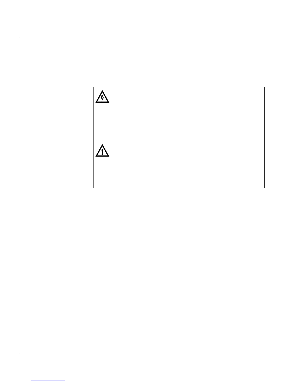
Safety Terms and Symbols
This manual uses the following safety terms and symbols. See your
NEO Safety Instructions and Precautions Guide for more information.
Table P-3. Safety Terms and Symbols Used in Manual
WARNING
Statements identifying conditions or practices
that can result in personal injury or loss of life:
High voltage is present. Uninsulated dangerous
voltage within the product’s enclosure may be
sufficient to constitute a risk of electric shock to
persons.
CAUTION
Statements identifying conditions or practices
that can result in damage to the equipment or
other property: Important operating and
maintenance (servicing) instructions in the
literature accompanying the product.
xii AES-3981 Installation and Operation Manual
Page 13

AES-3981 Installation and Operation Manual 1
Preliminary—Contents are proprietary and confidential. Do not photocopy or distribute.
Chapter 1
Introduction
Overview
AES-3981 modules are digital audio distribution amplifiers designed
for NEO 1RU and 3RU rack-mounted frames.
This chapter covers the following topics:
• “Applications” on page 4
• “Block Diagram” on page 7
• “Main Features” on page 3
• “Major Components” on page 5
• “Product Description” on page 2
See the FR-3901 and FR-3903 Installation and Operation Manual for
information about NEO frames. The frame manual includes information
about these items:
• General information about module unpacking, installation,
removal, navigation, configuration, and setup
• Card-edge screen savers
• State recovery parameters
•Fan modules
• Resource modules
• Alarm interconnect modules
• Power supplies
• Genesis adapters
• Servicing instructions
Note
Installation, navigation,
configuration, and setup
information is now included in
the NEO FR-3901, FR-3903,
and FR-3923 Mounting Frames
Installation and Operation
Manual. If your current NEO
frame manual is Edition A, B,
C, or D, you will need to
download an updated version
from our Web site
(www.broadcast.harris.com/
leitch) to access this
information.
Page 14

2 AES-3981 Installation and Operation Manual
Preliminary—Contents are proprietary and confidential. Do not photocopy or distribute.
Chapter 1: Introduction
Product Description
The NEO AES-3981 is a digital audio distribution amplifier for AES/
EBU audio signals for the NEO range of products. This module, as is
the case with all modules in the NEO family, can be controlled locally
via a front-edge display or from a remote location. Its remote
communications capability allows for control, monitoring, and
diagnostics using hardware control panels and/or a graphical user
interface.
The 1RU NEO control panel is uncluttered and simple to use. It has as
large a display as is practical, and a suitable number of buttons and
knobs to allow easy menu selection and parameter adjustment. The
aesthetic appearance of the panel is similar to that used for the 3RU
NEO Control panel, and matches the global Leitch/Harris styling
requirements.
The AES-3981 is a fully-featured single module product that includes a
front plug-in card module and back modules with balanced or coaxial
digital audio interfaces. Card edge and remote control of reclock mode,
EQ mode, and Alarm classification is provided. Signal presence is
provided locally and remotely.
Page 15

AES-3981 Installation and Operation Manual 3
Chapter 1: Introduction
Preliminary—Contents are proprietary and confidential. Do not photocopy or distribute.
Main Features
These are the main features of the AES-3981:
• AES frame rates up to 96kHz
• Balanced or coaxial interface
• Automatic or manual EQ
• Reclock and non-reclock modes
• Error detection and reporting
• Frame rate detection and reporting
• Looping coaxial inputs
• Looping or terminated balanced inputs
• Eight outputs
• Card edge and remote control/status
• Signal presence detection and reporting
Page 16

4 AES-3981 Installation and Operation Manual
Preliminary—Contents are proprietary and confidential. Do not photocopy or distribute.
Chapter 1: Introduction
Applications
The NEO platform is ideal for space-constrained operations demanding
full local and remote control capabilities in a routing solution. It is
especially useful where professional end-users require a small, flexible,
high quality (on-air quality) routing matrix with the ability to mix and
match signal formats and/or signal processing functions within the
same frame:
• Television production facilities
• Cable operators
• Production and post-production facilities
• Outside broadcast vans/trucks
• DBS satellite operations
Page 17
AES-3981 Installation and Operation Manual 5
Chapter 1: Introduction
Preliminary—Contents are proprietary and confidential. Do not photocopy or distribute.
Major Components
The AES-3981 consists of a front module and a back connector module.
The front module is installed from the front of the frame, and is
hot-swappable. The back connector module is installed from the rear of
the frame.
The front module accepts a single input signal from the back panel, then
equalizes and conditions the signal before driving the signal to eight
separate outputs. The input signal may also be reclocked if desired.
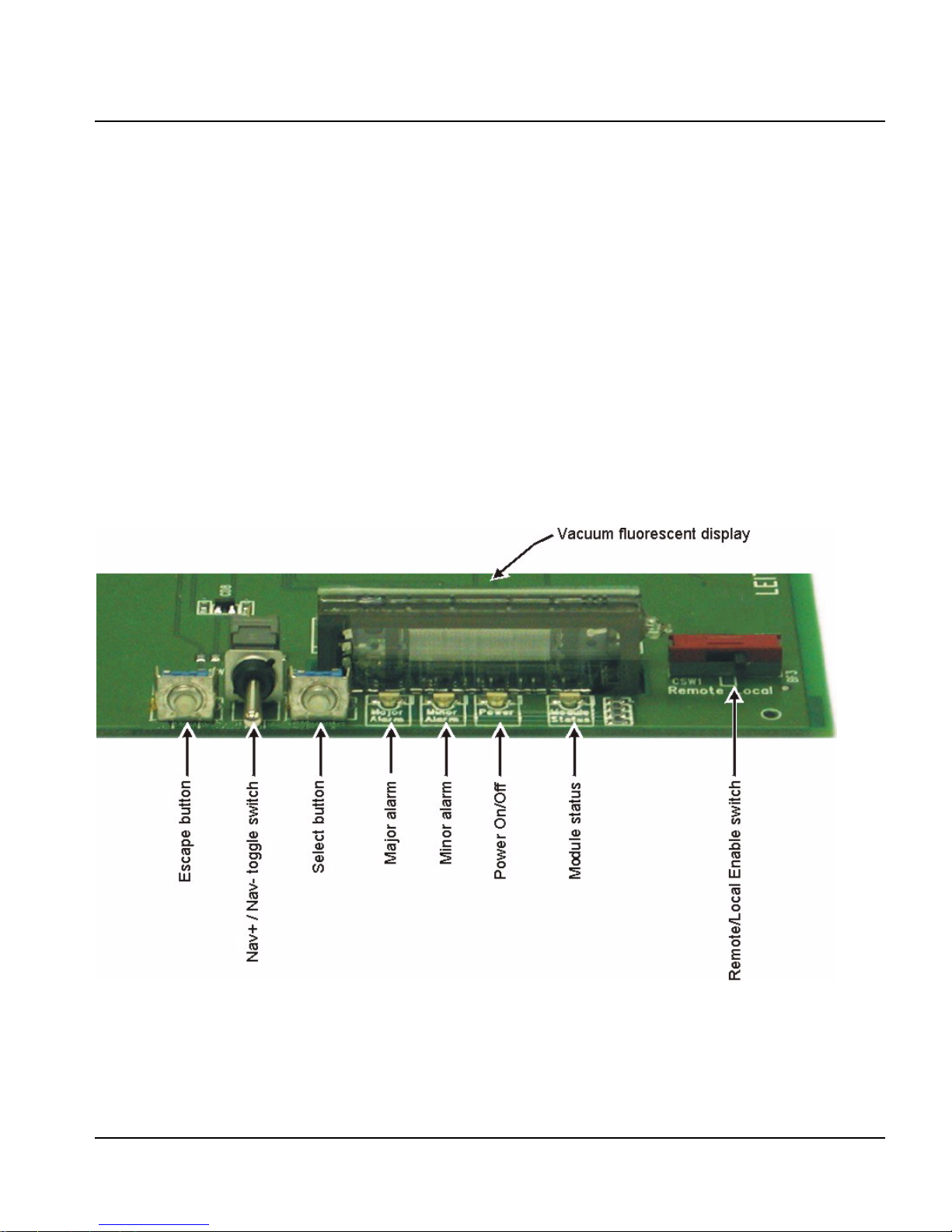
Front Module
Figure 1-1 illustrates the LEDs on the front module of the AES-3981.
Front modules are designated by the suffix “-FM.” For example, the
front module of the AES-3981 is the AES-3981-FM.
Figure 1-1. AES-3981 Front Module
Page 18

6 AES-3981 Installation and Operation Manual
Preliminary—Contents are proprietary and confidential. Do not photocopy or distribute.
Chapter 1: Introduction
Back Connector Module
The back modules provide the interface between the main module and
the signal cables. The coaxial back module contains one looping BNC
input and 8 BNC outputs. The balanced back module provides an input,
which is either terminated or looping, selectable via a back module
jumper. The one input and the eight outputs are transformer coupled,
with connectors being removable terminal strips.
In the NEO frame, the AES-3981 back connector module is placed
directly behind the front module, facing the rear. The AES-3981
supports either a coaxial interface or a balanced interface back module.
The balanced back module features 110Ω output impedance with a
jumper-selectable looping or 110Ω-terminated input. The input on the
AES-3981-B is bridging and may be used as such; however, we
recommend that the input be terminated with the back module
jumper for proper input return loss specification. Figure 1-2
illustrates balanced back module connections.
The coaxial back module features 75Ω output impedance and a looping
input. The input on the AES-3981-C is high impedance (looping)
and may be used as such; however, we recommend that the input be
terminated with a 75Ω termination for proper input return loss
specification. Figure 1-3 illustrates coaxial back module connections.
Figure 1-2. AES-3981-B (Balanced) Back Module
Figure 1-3. AES-3981-C (Coaxial) Back Module
Page 19

AES-3981 Installation and Operation Manual 7
Chapter 1: Introduction
Preliminary—Contents are proprietary and confidential. Do not photocopy or distribute.
Block Diagram
Figure 1-4. Functional Block Diagram of AES-3981
Page 20

8 AES-3981 Installation and Operation Manual
Preliminary—Contents are proprietary and confidential. Do not photocopy or distribute.
Chapter 1: Introduction
Page 21

AES-3981 Installation and Operation Manual 9
Preliminary—Contents are proprietary and confidential. Do not photocopy or distribute.
Chapter 2
Installation and Removal
Overview
Installation, navigation, configuration, and setup information is now
included in the NEO FR-3901, FR-3903, and FR-3923 Mounting
Frames Installation and Operation Manual. If your current NEO frame
manual is Edition A, B, C, or D, you will need to download an updated
version from the Web site (www.broadcast.harris.com/leitch
) to access
this information.
In this chapter, you can find information on the following topics.
• “Installing AES-3981 Modules” on page 10
• “Packing List” on page 10
• “Removing AES-3981 Modules” on page 10
• “Upgrading AES-3981 Firmware” on page 10
• “Correcting a Failed Upgrading Procedure” on page 15
CAUTION
Before installation, please read the NEO Safety and
Compliance Manual. This document contains
important information about the safe installation
and operation of NEO products.
Page 22

10 AES-3981 Installation and Operation Manual
Preliminary—Contents are proprietary and confidential. Do not photocopy or distribute.
Chapter 2: Installation and Removal
Packing List
The NEO AES-3981 module package includes these items:
• One front (main switch) module
• One back connector module
•One Installation and Operation Manual
Installing AES-3981 Modules
This module requires no specialized installation procedures. See the
NEO FR-3901, FR-3903, and FR-3923 Mounting Frames Installation
and Operation Manual for details about installing NEO modules.
Removing AES-3981 Modules
This module requires no specialized removal procedures. See the NEO
FR-3901, FR-3903, and FR-3923 Mounting Frames Installation and
Operation Manual for details about removing NEO modules.
Upgrading AES-3981 Firmware
Firmware upgrading is a routine procedure that you must perform to
install newer versions of software on the AES-3981 module. Pilot,
Co-Pilot, or Navigator software applications are required for this
procedure. You can use either the Discovery or the drag-and-drop
method. When performing the upgrading procedure, check the
appropriate README file to confirm which files are needed. Use care
to ensure that you upload the correct files to the intended module.
If for some reason the upgrade fails, the module may not respond to
controls and will appear to be non-functional. In that event, follow the
procedures described in “Correcting a Failed Upgrading Procedure” on
page 15.
Page 23

AES-3981 Installation and Operation Manual 11
Chapter 2: Installation and Removal
Preliminary—Contents are proprietary and confidential. Do not photocopy or distribute.
Upgrading the Firmware (Discovery Method)
Follow these steps to upgrade the firmware using the Discovery
method:
1. Download the most recent appropriate upgrade package from our
Web site or from your CD-ROM, and then unzip the upgrade
package.
2. If the affected module has not been discovered, perform the
Discovery operation, as described in your CCS software
application manual or online help.
3. Double-click the device icon.
The Configuration... window opens. On the Software Upgrade
tab, the /slotx/boot (where x is the slot number) directory appears
in the Select the device directory to transfer to: field.
4. Click Add, and in the Add Upgrade Files box, browse and select
the boot folder in the module’s upgrade; click OK.
The Add Upgrade Files box appears.
5. Select the file and then click OK.
6. Click Perform Transfer and then click Yes .
This may take several minutes.
7. Wait for the message File transfer to device succeeded in the
status bar.
If an fl0 folder is included in the .zip file, the files within that folder
must now be uploaded as shown below. (In some cases, the README
file may indicate other separate files must be uploaded instead.)
Follow these steps to upload the remaining files:
1. On the Software Upgrade tab, select the /slotx/fl0 (where x is the
slot number) directory in the Select the device directory to
transfer to: field.
2. Click Add, and in the Add Upgrade Files box, browse and select
the fl0 folder in the module’s upgrade package.
3. Click OK.
Page 24

12 AES-3981 Installation and Operation Manual
Preliminary—Contents are proprietary and confidential. Do not photocopy or distribute.
Chapter 2: Installation and Removal
4. Select the files shown in the Add Upgrade Files box, and then
click OK.
5. Select and delete unwanted files (for example: vxWorks.lzs) in the
Add upgrade files for transfer to device: field by clicking
Remove.
6. Click Perform Transfer and then click Yes .
7. Wait for the message File transfer to device succeeded.
This may take a moment.
8. Click Reboot Device and then click Yes.
9. Wait 30 seconds, and then close the Configuration... box.
The module name appears at the card edge.
Upgrading the Firmware (Drag-and-Drop Method)
Follow these steps to upgrade the firmware using the drag-and-drop
method:
1. Download the appropriate most recent upgrade package from our
Web site or from your CD-ROM, and then unzip the upgrade
package.
2. If the affected module has not been discovered by your CCS
software application, enter the Build mode, and then drag or copy
and paste the module’s device icon from the catalog folder into the
Network or Discovery folder.
3. Right-click the device icon and then select Properties.
CAUTION
You must delete unwanted files in the Add upgrade
files for transfer to device: field before transferring
the files. Otherwise, the upgrading procedure will
fail.
Page 25

AES-3981 Installation and Operation Manual 13
Chapter 2: Installation and Removal
Preliminary—Contents are proprietary and confidential. Do not photocopy or distribute.
4. On the NRO or Device tab of the Navigation Properties box, enter
the IP address of the frame that holds the module. (See Figure 2-1.)
Figure 2-1. Navigation Properties Box
5. In the last field, enter the slot number of the module, and then close
the window.
6. Double-click the device icon.
The Configuration... window opens. On the Software Upgrade
tab, the /slotx/boot (where x is the slot number) directory appears
in the Select the device directory to transfer to: field.
7. Click Add, and in the Add Upgrade Files box, browse and select
the boot folder in the module’s upgrade.
8. Click OK.
The Add Upgrade Files box appears.
9. Select the file and then click OK.
10. Click Perform Transfer and then click Ye s.
This may take several minutes.
CAUTION
Do not make changes in the third field (located
above and to the right of the Set Default button.)
Do not make changes in
this field
Enter frame IP number here
Page 26

14 AES-3981 Installation and Operation Manual
Preliminary—Contents are proprietary and confidential. Do not photocopy or distribute.
Chapter 2: Installation and Removal
11. Wait for the message File transfer to device succeeded in the
status bar.
If an fl0 folder is included in the .zip file, the files within that folder
must now be uploaded as shown below. (In some cases, the README
file may indicate other separate files must be uploaded instead.)
Follow these steps to upload the remaining files:
1. On the Software Upgrade tab, select the /slotx/fl0 (where x is the
slot number) directory in the Select the device directory to
transfer to: field.
2. Click Add, and in the Add Upgrade Files box, browse and select
the fl0 folder in the module’s upgrade package.
3. Click OK.
4. Select the files shown in the Add Upgrade Files box, and then
click OK.
5. Select and delete unwanted files (for example: vxWorks.lzs) in the
Add upgrade files for transfer to device: field by clicking
Remove.
6. Click Perform Transfer and then click Yes .
7. Wait for the message File transfer to device succeeded.
This may take a moment.
8. Click Reboot Device and then click Yes.
9. Wait 30 seconds and then close the Configuration... box.
The module name appears at the card edge.
CAUTION
You must delete unwanted files in the Add upgrade
files for transfer to device: field before transferring
the files. Otherwise, the upgrading procedure will
fail.
Page 27

AES-3981 Installation and Operation Manual 15
Chapter 2: Installation and Removal
Preliminary—Contents are proprietary and confidential. Do not photocopy or distribute.
Correcting a Failed Upgrading Procedure
Firmware upgrades may fail in the event of network interruptions,
power failures, or if too much data is uploaded to the NEO module.
Often, uploads of too much data can occur for one of the following
reasons:
• The boot file (typically vxWorks.lzs) was accidentally uploaded
during the fl0 procedure, instead of the boot procedure.
• Files were sent to the wrong NEO module.
• The particular hardware version of the module requires only some
(but not all) of the available fl0 files.
• The upgrade .zip file was mistakenly sent to the module.
All of these problems can be corrected by re-installing the firmware
while in a fail-safe mode, as described in the following pages. When
you are performing this procedure, check the appropriate README file
to confirm which files are needed. Use care to ensure that you upload
the correct files to the intended module.
Setting the Module to Fail-Safe Loader Mode
Follow these steps to set a NEO module to the fail-safe loader mode:
1. Remove the affected module from the NEO frame.
2. Press the Nav switch down while simultaneously pressing both the
Escape and Enter buttons.
3. While still pressing the buttons and the navigation switch, reinsert
the module into the frame and hold for approximately three seconds
until the display on the module reads Offline-H (or Offline-L)
Upload Required.
Upgrading the Firmware in Fail-Safe Mode
Follow these steps to upgrade the firmware in the fail-safe mode:
1. Download the most recent appropriate upgrade package from our
Web site or from your CD-ROM, and then unzip the upgrade
package.
Note
To successfully upgrade the
firmware, you must follow these
steps in the exact sequence
described.
Page 28

16 AES-3981 Installation and Operation Manual
Preliminary—Contents are proprietary and confidential. Do not photocopy or distribute.
Chapter 2: Installation and Removal
2. If the affected module has not been discovered by your CCS
software application, enter the Build mode, and then drag or copy
and paste the module’s device icon from the catalog folder into the
Network or Discovery folder.
3. Right-click the device icon and then select Properties.
4. On the NRO or Device tab of the Navigation Properties box, enter
the IP address of the frame that holds the module. (See Figure 2-2.)
Figure 2-2. Navigation Properties Box
5. In the last field, enter the slot number of the module, and then close
the window.
6. Double-click the device icon.
The Configuration... box opens. On the Software Upgrade tab,
the /slotx/boot (where x is the slot number) directory appears in the
Select the device directory to transfer to: field.
7. Click Add, and in the Add Upgrade Files box, browse and select
the boot folder in the module’s upgrade.
8. Click OK.
9. Select the file and then click OK.
CAUTION
Do not make changes in the third field (located
above and to the right of the Set Default button.)
Do not make changes in
this field
Enter frame IP number here
Page 29

AES-3981 Installation and Operation Manual 17
Chapter 2: Installation and Removal
Preliminary—Contents are proprietary and confidential. Do not photocopy or distribute.
10. Click Perform Transfer and then click Ye s.
This may take several minutes.
11. Wait for the message File transfer to device succeeded in the
status bar.
Rebooting the Module
Follow these steps to reboot the affected NEO module:
1. Click Reboot Device, and then click Ye s.
After the module has rebooted, a message box advises you to wait
until the device has rebooted.
2. Wait 30 seconds.
3. On the Software Upgrade tab, select the /slotx/fl0 (where x is the
slot number) directory in the Select the device directory to
transfer to: field.
4. Click Add, and then browse and select the fl0 folder in the
module’s upgrade package.
5. Click OK.
6. Select the files shown in the Add Upgrade Files box, and then
click OK.
7. Select and delete unwanted files (for example: vxWorks.lzs) in the
Add upgrade files for transfer to device: field by clicking
Remove.
8. Click Perform Transfer and then click Yes .
9. Wait for the message File transfer to device succeeded.
This may take a moment.
10. Click Reboot Device and then click Yes.
11. Wait 30 seconds, and then close the Configuration... box.
The module name appears at the card edge.
Note
Some NEO modules will reboot
automatically. In these cases,
the Reboot button will be
grayed out. During this time, the
module’s card-edge display will
show the word Rebooting
before the name of the module
appears. These modules do not
require the fl0 file.
CAUTION
You must delete unwanted files in the Add upgrade
files for transfer to device: field before transferring
the files. Otherwise, the upgrading procedure will
fail.
Page 30

18 AES-3981 Installation and Operation Manual
Preliminary—Contents are proprietary and confidential. Do not photocopy or distribute.
Chapter 2: Installation and Removal
Page 31

AES-3981 Installation and Operation Manual 19
Preliminary—Contents are proprietary and confidential. Do not photocopy or distribute.
Chapter 3
Operation
Overview
Installation, navigation, configuration, and setup information is now
included in the NEO FR-3901, FR-3903, and FR-3923 Mounting
Frames Installation and Operation Manual. If your current NEO frame
manual is Edition A, B, C, or D, you will need to download an updated
version from our Web site (www.broadcast.harris.com/leitch
) to access
this information.
The following topics are found in this chapter:
• “Alarms” on page 25
• “LEDs and Module Indicators” on page 27
• “Navigating the Operator and All Lists” on page 21
• “Operation Notes” on page 20
• “Operator and All List Parameters” on page 22
• “Setup Parameters” on page 24
• “State Recovery Parameter Availability” on page 26
Page 32

20 AES-3981 Installation and Operation Manual
Preliminary—Contents are proprietary and confidential. Do not photocopy or distribute.
Chapter 3: Operation
Operation Notes
When using the AES-3981 module, observe the following operation
notes:
• If you change parameters within 16 seconds after the AES-3981
banner first appears on the VFD, your changes will not be saved.
Parameter changes that you make after this 16-second delay will be
saved and restored if the module loses power and must be restarted.
• Although the effect of a parameter change may appear to be
immediate, the module requires 20 seconds to save the latest
change. If another change is made during these 20 seconds, the first
parameter change and the second parameter change will not be
saved until 20 seconds after the second parameter change. There is
no limit to the number of changes that can be made within 20
seconds of each other. However, none of these changes will be
saved until 20 seconds after the last parameter change.
• The AES-3981 module automatically sets its parameters to the ones
saved last.
• When adjusting frame delay using the DlyRange parameter, the
range of vertical phase (VPhase) is limited to two lines less than a
full frame when the DlyRange is set to the maximum value. When
DlyRange is less than maximum, the full frame line range is
available for adjustment in the VPhase parameter.
CAUTION
Failure to observe these Operation Notes will result
in accidental changes to the module’s parameter
settings.
Page 33

AES-3981 Installation and Operation Manual 21
Chapter 3: Operation
Preliminary—Contents are proprietary and confidential. Do not photocopy or distribute.
Navigating the Operator and All Lists
To navigate, then view or change a parameter from the Operator or All
List, follow these steps:
1. Open the front panel of the NEO frame.
2. Press any card-edge control to turn on the VFD screen.
The message AES-3981 will appear. If a previous user has left the
display at a different parameter name, repeatedly press the Escape
button until AES-3981 appears.
3. Press the Enter button.
The name of the first parameter option in the list will appear.
4. Push the Enter button again to access the options for the parameter
displayed on the VFD screen.
OR
Press the Nav+/Nav- switch down repeatedly to view other
parameters, and then press Enter to access an item’s parameter
options.
5. Press the Nav+/Nav- switch up or down to scroll through the
different selectable parameter options, and then press Enter to
select the value you want.
OR
Press the Nav+/Nav- switch up or down to adjust the numeric
parameter value, and then press Enter.
6. Close the front panel of the frame to ensure the cooling system will
continue to operate properly.
Note
After several seconds of
inactivity, a scrolling message
will appear, describing the
purpose of the currently selected
parameter.
Page 34

22 AES-3981 Installation and Operation Manual
Preliminary—Contents are proprietary and confidential. Do not photocopy or distribute.
Chapter 3: Operation
Operator and All List Parameters
The All List is a long flat list of all the available parameters, arranged
from the most-used to the least-used. It is intended for a “Supervisor”
security designation. The Operator List is a condensed version of the
All List, and is intended for an “Operator” security designation.
• The AES-3981 parameters listed on page 22 through page 23 are
sorted in the order that they appear in the Operator and/or All List.
• Default values are marked with an asterisk (*).
• Parameters accessed only from within the All List are shaded in
gray.
• Parameters with the symbol [RO] are read-only. Read-only
parameter default values are not highlighted, as they report system
status indicators.
• Information in brackets provides further explanation of a parameter.
This information will not appear on the card edge.
See “Navigating the Operator and All Lists” on page 21 for instructions
on navigating this list using card-edge controls.
Note
You can reset the default values
for all of the parameters
automatically via the FctryRcl
parameter.
Table 3-1. Operator and All List Parameters
Card-Edge ID Parameter Name Description User Range
Reclk Mode Reclock mode Reclocking mode select
• Auto*
• Reclocked
• Bypass
EQ_Mode Input EQ mode Input equalization mode
• Auto EQ*
• Manual EQ
EQ_Adj Input EQ adjustment EQ adjustment for input
cable length
0 to 600 (300*)
BM_Type [RO] Back module type Back module type
detection
• Coax BM
•Bal BM
• Invalid BM
•Absent BM
Frame Rate [RO] AES frame rate AES frame rate detection
• 96 kHz
• 88.2 kHz
• 48 kHz
• 44.1 kHz
• 32 kHz
• Fs unknown
Page 35

AES-3981 Installation and Operation Manual 23
Chapter 3: Operation
Preliminary—Contents are proprietary and confidential. Do not photocopy or distribute.
AES_Error [RO] AES error AES error detect
• No error
•Validity
• Reserved
• Sample
• CRC
• Parity
•Biphase
•No Lock
Sig_Pres [RO] Signal presence Signal presence detect
•No
•Yes
+5V_Alarm [RO] +5V power alarm +5 volts out of range
• No alarm
•Alarm
-5V Alarm [RO] -5V power alarm -5 volts out of range
• No alarm
•Alarm
+3.3V Alrm [RO] +3.3V power alarm +3.3 volts out of range
• No alarm
•Alarm
Setup Setup Parameters Sets the parameters for
display and usability (see
page 39 for a complete
list of Setup parameters
and factory default
settings)
Various
Table 3-1. Operator and All List Parameters (Continued)
Card-Edge ID Parameter Name Description User Range
Page 36

24 AES-3981 Installation and Operation Manual
Preliminary—Contents are proprietary and confidential. Do not photocopy or distribute.
Chapter 3: Operation
Setup Parameters
You can modify the Setup parameters to configure the card-edge
controls for your personal needs. The Setup section appears at the end
of all three navigation lists and consists of these items:
•Alarms
• Navigation modes
• Adjustment modes
• Browse modes
• Scroll modes
• Display intensity
• Parameter descriptions
•Name
• FrameIP
•Sync full
• About mode
See Appendix A: “Tree View Navigation” for the structure of the Setup
menu. See your NEO FR-3901, FR-3903, and FR-3923 Mounting
Frames Installation and Operation Manual for more information on
Setup items, including descriptions and operation notes.
To access the Setup section:
1. Press any card edge control button or the toggle switch to turn on
the VFD display.
The message AES-3981 will appear. (If a previous user has left the
display at a different parameter name, repeatedly press the Escape
button until AES-3981 appears.)
2. Scroll to Setup.
3. Press the Select button.
Note
Setup parameters on a local or
remote control panel may be
different from the card-edge
parameters described here.
Page 37

AES-3981 Installation and Operation Manual 25
Chapter 3: Operation
Preliminary—Contents are proprietary and confidential. Do not photocopy or distribute.
Alarms
The AES-3981 provides a default list of 6 alarms. (Table 3-2 on page 26
lists the major and minor alarms, and their descriptions.) You can
disable any alarm by modifying the Alarms parameters in the Setup
section.
When you select Alarms, all of the active alarms are visible in the
display, below Config (Configurations). If no alarms are active, only
Config appears.
Alarm Synchronization
Alarm synchronization is available for this module if your NEO frame
contains a 3901RES-E resource module that supports the feature. When
active, alarm synchronization ensures that the alarm configuration
settings of card-edge controls and the CCS control software and control
panels are consistent.
If the AES-3981 module is set for local control, the alarm settings will
appear the same at both the card edge and via CCS, but the settings can
only be changed using the card-edge controls. If the module is set for
remote control, the alarm settings can be changed via both the card edge
and CCS control software and control panels. Alarm configuration
settings undergo DejaView (state recovery) automatically. This means
that when a module is hot-swapped, the alarm configuration for the new
module is updated to the settings of the module that was previously in
that slot. See “State Recovery Parameter Availability” on page 26 for
more information.
Identifying the Cause of an Alarm
To identify the reason for an alarm, select Alarm, scroll to an active
alarm, then press Select. A scrolling message that describes the cause of
the fault will appear on the VFD.
Enabling or Disabling an Alarm Parameter
To enable or disable an alarm parameter, follow these steps:
1. Select Alarms, then select Config, then press Select.
2. Select one of the alarm parameters, then press Select.
3. Press Enabled or Disabled.
Page 38

26 AES-3981 Installation and Operation Manual
Preliminary—Contents are proprietary and confidential. Do not photocopy or distribute.
Chapter 3: Operation
4. Press Select to activate the selection.
Restoring Default Settings
To restore the alarms to their default settings, follow these steps:
1. Select Alarms, select Config, then press Select.
2. Scroll down the list of alarms, then select Reset.
3. Press Select to activate the selection.
Table 3-2 lists the default alarm settings for the AES-3981. You can
enable or disable these settings, but you cannot change the level of the
alarm.
State Recovery Parameter Availability
The parameter settings for this module are automatically saved onto the
AES-3981 resource module installed in your NEO frame every five
minutes. If a module should fail and be replaced with a cold spare, the
state parameters can be automatically recovered. For more information
on this feature, see the NEO FR-3901, FR-3903, and FR-3923
Mounting Frames Installation and Operation Manual (Edition E and
above).
Table 3-2. Default AES-3981 Alarms
Card-Edge ID Alarm Name Alarm Level Description
+3.3V Alrm +3.3V power alarm Major +3.3 volts out of
range
+5V_Alarm +5V power alarm Major +5 volts out of range
–5V Alarm -5V power alarm Major –5 volts out of range
AES_Error AES error Minor AES error detect
BM_Type Back module type Minor Back module type
detection
Sig_Pres Signal presence Minor Signal presence
detect
Page 39

AES-3981 Installation and Operation Manual 27
Chapter 3: Operation
Preliminary—Contents are proprietary and confidential. Do not photocopy or distribute.
LEDs and Module Indicators
General Information
The AES-3981 has four standard module indicators:
• Major alarm
•Minor alarm
•Power
• Module status
These indicators are located on the card edge of the front module,
directly in front of the VFD. (See Figure 3-1.)
The AES-3981 also generates alarm signals to alert users of failures or
impending failures within the module. These alarm signals are found in
the following locations:
• As red or yellow LEDs on the 3901AIC Alarm Interconnect
Module or the 3901RES-E Resource Module (visible via light
pipes through the frame’s front panel)
• As part of a list of activated alarms found in the Setup menu
• In external systems connected to the alarm contact closures at
the back of the NEO frames
• On a PC screen where CCS Pilot™ CCS Navigator™, or
another GUI-based software control application
Page 40

28 AES-3981 Installation and Operation Manual
Preliminary—Contents are proprietary and confidential. Do not photocopy or distribute.
Chapter 3: Operation
Card-Edge Locations
Figure 3-1 illustrates the locations of the LEDs and module indicators
on the AES-3981 card edge.
Figure 3-1. Card-Edge LEDs and Module Indicators, Top View
Local/Remote switch
Top view
Nav+/Nav- switch
(up/down)
Extractor handle
Module
Status
Mino
r
Alar
m
Majo
r
Alar
m
Powe
r
SW1
Remote
Local
Nav +
Nav -
Enter
Esc
Major
alarm
Minor
alarm
Power
Module
status
Standard module indicators
Escape pushbutton
Select pushbutton
Page 41

AES-3981 Installation and Operation Manual 29
Chapter 3: Operation
Preliminary—Contents are proprietary and confidential. Do not photocopy or distribute.
Module Indicator Descriptions
Table 3-3. Color Meaning of Module Indicators
LED Name Color Meaning
Major Alarm Red One or more of the following problems in the
AES-3981 module has occurred:
• +3.3 volts out of range
• +5 volts out of range
• –5 volts out of range
Minor Alarm Yellow One or more of the following problems in the
AES-3981 module has occurred:
• AES error detect
• Back module type detection
• Signal presence detect
Power Green Power is being provided to the module.
Module Status Green Module is configured, loaded, and
operational.
Page 42

30 AES-3981 Installation and Operation Manual
Preliminary—Contents are proprietary and confidential. Do not photocopy or distribute.
Chapter 3: Operation
Page 43

AES-3981 Installation and Operation Manual 31
Preliminary—Contents are proprietary and confidential. Do not photocopy or distribute.
Chapter 4
Specifications
Overview
The tables in this chapter list the following specifications for the
AES-3981 module.
• “AES-3981 Digital Input Specifications” on page 32
• “AES-3981 Digital Output Specifications” on page 33
• “Performance Specifications” on page 34
• “Indications” on page 34
• “Power Consumption Specifications” on page 35
• “Temperature Specifications” on page 35
Specifications and designs are subject to change without notice.
All specifications conform to the guidelines set forth in AES3-1992
(r 1997) in the balanced configuration, and conform to AES3id-2001
and SMPTE 276M-1995 in the unbalanced configuration.
Page 44

32 AES-3981 Installation and Operation Manual
Preliminary—Contents are proprietary and confidential. Do not photocopy or distribute.
Chapter 4: Specifications
Input
Table 4-1. AES-3981 Digital Input Specifications
Item
Specification
With Balanced Back
Module
With Coaxial Back
Module
Number of inputs One, looping or
terminated
One, looping
Type Balanced, transformer
coupled
Differential, AC
coupled
Connector Removable terminal
strip
BNC
Impedance High Z or 110Ω, jumper
selectable
High Z
Return loss N/A >30 dB, 0.1 MHz to 6
MHz
Signal amplitude 0.2 Vpp to 7 Vpp 0.1 Vpp to 2 Vpp
Page 45

AES-3981 Installation and Operation Manual 33
Chapter 4: Specifications
Preliminary—Contents are proprietary and confidential. Do not photocopy or distribute.
Output
Table 4-2. AES-3981 Digital Output Specifications
Item
Specification
With Balanced Back
Module
With Coaxial Back
Module
Number of outputs 8 8
Type Balanced, transformer
coupled
Unbalanced
Connector Removable terminal
strip
BNC
Impedance 110Ω 75Ω
Return loss N/A >35 dB, 0.1 MHz to 6
MHz
Signal amplitude 5 Vpp ± 1V into 110Ω
load
1.0 Vpp ± 10% into
75Ω load
DC offset 0.0 V ± 50 mV 0.0 V ± 50 mV
Rise/fall time 5 ns to 30 ns 30 ns to 44 ns
Page 46

34 AES-3981 Installation and Operation Manual
Preliminary—Contents are proprietary and confidential. Do not photocopy or distribute.
Chapter 4: Specifications
Miscellaneous
Table 4-3. Performance Specifications
Item Specification
Equalization modes Automatic or manual
Input cable length
• Up to 984 ft (300 m) Belden 8451
or equivalent (balanced)
• Up to 1,968 ft (600 m) Belden
8281 or equivalent (coaxial)
Reclocking modes Reclocked, non-reclocked, or auto
Propagation delay
• < 600 ns (reclocked)
• < 100 ns (non-reclocked)
Intrinsic jitter < 5 ns
AES frame rates 30 kHz - 100 kHz (reclocked)
Data rates Up to 25 Mb/s, 50% duty cycle
(non-reclocked)
Table 4-4. Indications
Item Specification
Equalization mode
• Automatic
• Manual
Manual EQ cable length
• 0 ft to 984 ft (0 m to 300 m)
twisted pair Belden 8451 or
equivalent
• 0 ft to 1,968 ft (0 m to 600 m)
coaxial Belden 8281 or equivalent
Reclocking mode
• Reclocked
• Non-reclocked
• Auto
Back module type
• Coaxial
• Balanced
• Invalid
• Absent
Page 47

AES-3981 Installation and Operation Manual 35
Chapter 4: Specifications
Preliminary—Contents are proprietary and confidential. Do not photocopy or distribute.
Signal present
•Yes
•No
AES frame rate
• 32 kHz
• 44.1 kHz
• 48 kHz
• 88.2 kHz
• 96 kHz
• Unknown
Error indications
• +5V, -5V, or +3.3V power out of
range
• Back module type invalid or
absent
• Signal not present
• AES not locked
• AES biphase encoding error
• AES parity error
• AES CRC error
• AES slipped sample
• AES validity bit set (non-audio)
Table 4-5. Power Consumption Specifications
Item Specification
Power consumption 3.59 W
Table 4-6. Temperature Specifications
Item Specification
Operating temperature 32°F to 122°F (0°C to 50°C)
Performance temperature 41°F to 104°F (5°C to 40°C)
Table 4-4. Indications (Continued)
Item Specification
Page 48

36 AES-3981 Installation and Operation Manual
Preliminary—Contents are proprietary and confidential. Do not photocopy or distribute.
Chapter 4: Specifications
Page 49

AES-3981 Installation and Operation Manual 37
Preliminary—Contents are proprietary and confidential. Do not photocopy or distribute.
Appendix A
Tree View Navigation
Overview
The Tree View is one of the three navigation modes available on the
AES-3981 modules. Unlike the other navigation modes, the Tree View
is a multilevel list of parameters, arranged in the following main
groups:
• “Input” on page 39
• “Output” on page 39
• “Status” on page 39
• “Setup” on page 39
(See “Setup Parameters” on page 24 for more information on the
Setup parameters that govern the operation of the card-edge
controls.)
This appendix consists of the instructions for navigating the Tree View
list (see page 38) and the Tree View parameter list (see page 39).
Page 50

38 AES-3981 Installation and Operation Manual
Preliminary—Contents are proprietary and confidential. Do not photocopy or distribute.
Appendix A: Tree View Navigation
Navigating the Tree View
To navigate and then view or change a parameter from the Tree View,
follow these steps:
1. Open the front panel of the NEO frame.
2. Press any card edge control button or the toggle switch to turn on
the VFD display.
The message AES-3981 will appear as the banner on the card-edge
display screen.
3. Press the Select button.
The first two items in the Level One list will appear.
4. Click Nav- (down) on the Nav-/Nav+ switch to view more items in
the list.
5. Choose the desired item in the list, then press the Select button.
The Level Two list will appear.
6. Repeat steps 4 and 5 to view more items in Levels Two, Three, and
Four.
7. If the parameter is numeric, slide the bar to the desired parameter
using the Nav+/Nav- switch.
OR
Choose the desired item in the Level Four list, then press the Select
button.
8. Once the Level Four parameter is set or viewed, you can leave the
parameter in its current state, or return to the banner. To return to
the card-edge display banner, repeatedly press the Escape button.
9. Close the front panel again after you have completed the procedure
to prevent the frame from overheating.
Note
If you do not wish to make
changes to your settings, return
to the previously selected item
in the list, then press Escape to
move up a level.
Note
After several seconds of
inactivity, a scrolling message
will appear, describing the
purpose of the currently selected
parameter.
Page 51

AES-3981 Installation and Operation Manual 39
Appendix A: Tree View Navigation
Preliminary—Contents are proprietary and confidential. Do not photocopy or distribute.
Tree View Parameters
Unlike the Operator and All List navigation modes, the Tree View is a
multilevel structure that includes all of the available card-edge
parameters. Parameters with the abbreviation [RO] are “read-only.”
See page 38 for instructions on navigating the Tree View.
Input
Other
EQ_Mode
(Options: Auto, Manual)
EQ_Adj
(Range: 0– 600m)
Output
Other
Reclk Mode
(Options: Auto, Reclocked, Bypass)
Status
Other
BM_Type [RO]
(Options: Coaxial, Balanced, Invalid, Absent)
Frame Rate [RO]
(Options: 96kHz, 88.2kHz, 48kHz, 44.1kHz, 32kHz,
Unknown)
AES Error [RO]
(Options: No AES Error, AES validity bit is set,
Slipped Sample, CRC Error, AES Parity Error,
Biphase Encoding Error, AES Not Locked)
Sig_Pres [RO]
(Options: Yes, No)
+5V Alarm [RO]
(Options: Yes, No)
–5 Alarm [RO]
(Options: Yes, No)
+3.3 Alarm [RO]
(Options: Yes, No)
Setup
Alarms
Config
BM_Type [RO]
(Options: Coaxial, Balanced, Invalid, Absent)
Page 52

40 AES-3981 Installation and Operation Manual
Preliminary—Contents are proprietary and confidential. Do not photocopy or distribute.
Appendix A: Tree View Navigation
AES Error [RO]
(Options: No AES Error, AES validity bit is set,
Slipped Sample, CRC Error, AES Parity Error,
Biphase Encoding Error, AES Not Locked)
Sig_Pres [RO]
(Options: Yes, No)
+5V Alrm
(Options: Enabled, Disabled)
-5V Alrm
(Options: Enabled, Disabled)
+3.3V Alrm
(Options: Enabled, Disabled)
Reset
Nav Mode
(Options: Oper List, All List, Tree View)
SelPar Adj
(Options: Immediate, Delayed)
Brws Mode
(Options: Param List, Param+Val)
Scrl Mode
(Options: Wrap, Don’t Wrap)
Disp Inten
(Options: 100%, 50%, 25%, 12%)
Param Desc
(Options: Disabled, Enabled)
Name
(Options: AES-3981)
Frame IP
(Options: IP Address, Subnet, Gateway)
Sync Full
(Options: No, Yes)
About [RO]
FW_Rev
Page 53

AES-3981 Installation and Operation Manual 41
Index
Keywords
A
Add Upgrade Files box 11–17
Alarms
default settings 26
disabling alarms 25
enabling alarms 25
identifying causes 25
restoring defaults 26
synchronization 25
All list
navigation 21
parameters 22–23
Applications 4
B
Back connector module 6
Block diagram, functional 7
Boot file 11, 13–15
C
Card-edge controls 5
Configuration
configuration... window 11–17
Controls, card-edge 5
Correcting a failed upgrade 15
D
Description, product 2
Discovery method of upgrading 11–12
Documents, obtaining ix
Drag-and-drop method of upgrading 12–14
F
Fail-safe procedure 15
Features 3
Firmware upgrading 10–17
fl0 folder 11, 14, 17
Front module 5
I
Indication specifications 34–35
Input specifications 32
Installation and removal
correcting a failed upgrading procedure 15
installing modules 10
packing list 10
removing modules 10
upgrading firmware 10–17
Installing modules 10
Introduction
applications 4
back connector module 6
block diagram, functional 7
card-edge controls 5
front module 5
main features 3
major components 5–6
product description 2
Page 54

42 AES-3981 Installation and Operation Manual
Index
L
LEDs 27–29
Lists
All list 22–23
Operator list 22–23
packing list 10
tree view list 39–40
M
Main features 3
Main switch module. See Front module
Major components 5–6
Manual information vii–ix
Module indicators 27–29
Modules
back connector module 6
front module 5
installing modules 10
LEDs 27–29
main switch module. See Front module
module indicators 27–29
rebooting modules 17
removing modules 10
unpacking modules ix
N
Navigating lists
All list 21
Operator list 21
tree view list 38
Navigation Properties box 13, 16
O
Obtaining documents ix
Operation
alarms
cause identification 25
default settings 26
disabling alarms 25
enabling alarms 25
restoring defaults 26
synchronization 25
LEDs 27–29
module indicators 27–29
navigating the All list 21
navigating the Operator list 21
operation notes 20
parameters
All list 22–23
Operator list 22–23
setup 24
state recovery parameter availability 26
Operation notes 20
Operator list
navigation 21
parameters 22–23
Output specifications 33
P
Packing list 10
Parameters
All list 22–23
Operator list 22–23
setup 24
tree view list 39–40
Performance specifications 34
Power consumption specifications 35
Product description 2
R
Rebooting modules 12, 17
Removing modules 10
S
Safety
compliances x
standards x
symbols xii
terms xii
Setup parameters 24
Software upgrade 10–17
Software Upgrade tab 11–13
Specifications
indication specifications 34–35
input specifications 32
output specifications 33
performance specifications 34
power consumption specifications 35
Page 55

AES-3981 Installation and Operation Manual 43
Index
temperature specifications 35
T
Temperature specifications 35
Tree view
navigation 38
parameters 39–40
U
Unpacking modules ix
Upgrading firmware 10–17
discovery method 11–12
drag-and-drop method 12–14
V
vxWorks.lzs file 12, 14–15, 17
Page 56

44 AES-3981 Installation and Operation Manual
Index
 Loading...