

Page 1

ADC 100 Device Server
User’s Guide
Page 2

Page 3

HARRIS SOFTWARE LICENSE AGREEMENT
!"#$%#&'%"(%)*'%&"()+,$'%,-.%"/'$,)0"-%1,-#,2%1',-&%3"#%,4$''%)"%5'6"1'%5"#-.%53%)*'%
)'$1&%"(%)*0&%206'-&'%,4$''1'-)7%8(%3"#%."%-")%,4$''%)"%)*'%)'$1&%"(%)*0&%,4$''1'-)9%."%-")%
#&'%)*'%&"()+,$'%,-.%/$"1/)23%$')#$-%)*'%'-)0$'%/,6:,4'9%,2"-4%+0)*%,-3%")*'$%/$".#6)%
1,)'$0,2&9%)"%)*'%/2,6'%+*'$'%3"#%"5),0-'.%0)%("$%,%(#22%$'(#-.7%
%
1. License
;,$$0&%*'$'53%4$,-)&%)"%3"#%)*'%$04*)%)"%#&'%)*'%<"()+,$'%"-23%"-%,%&0-42'%=>?%,)%,%
)01'9%,)%,%&0-42'%2"6,)0"-7%!"#%1,3%1,:'%"-'%6"/3%"(%)*'%<"()+,$'%0-%1,6*0-'%
$',.,52'%("$19%&"2'23%("$%5,6:#/%/#$/"&'&7%@*'%'-62"&'.%<"()+,$'%,-.%,-3%+$0))'-%
1,)'$0,2&%A)*'%BC'('$'-6'%D#0.'EF%($"1%;,$$0&%,$'%206'-&'.9%-")%&"2.9%)"%3"#%("$%#&'%
"-23%#/"-%)*'%)'$1&%"(%)*0&%G4$''1'-)7%;,$$0&%&'$H'&%,-3%$04*)&%-")%'I/$'&&23%4$,-)'.%
)"%3"#%#-.'$%)*0&%G4$''1'-)7%!"#%"+-%)*'%1,4-')06%"$%")*'$%/*3&06,2%1'.0#1%"-%
+*06*%)*'%&"()+,$'%0&%"$040-,223%"$%&'J#'-)23%$'6"$.'.%"$%(0I'.9%5#)%;,$$0&%$'),0-&%
"+-'$&*0/%"(%)*'%<"()+,$'%$'6"$.'.%"-%)*'%"$040-,2%.0&:%,-.%,22%&'J#'-)%6"/0'&%"(%
)*'%<"()+,$'9%$'4,$.2'&&%"(%)*'%("$1%"$%1'.0,%"-%+*06*%)*'%"$040-,2%,-.%")*'$%6"/0'&%
1,3%'I0&)7%
%
2. Proprietary Rights
@*'%<"()+,$'%,-.%)*'%C'('$'-6'%D#0.'%6"-),0-%)$,.'%&'6$')&7%!"#%1,3%-")%.'6"1/02'9%
$'H'$&'%'-40-''$9%.0&,&&'152'%"$%")*'$+0&'%$'.#6'%)*'%<"()+,$'%)"%,%*#1,-%
/'$6'0H,52'%("$17%@*'%<"()+,$'%,-.%)*'%C'('$'-6'%D#0.'%,$'%6"/3$04*)'.7%!"#%1#&)%
$'/$".#6'%"-%',6*%6"/3%;,$$0&K&%6"/3$04*)%-")06'%,-.%,-3%")*'$%/$"/$0'),$3%2'4'-.&%
)*,)%+'$'%"-%)*'%"$040-,2%6"/0'&%&#//20'.%53%;,$$0&7%!"#%1,3%-")%1".0(39%,.,/)9%
)$,-&2,)'9%$'-)9%2',&'9%2",-9%$'&'22%.0&)$05#)'9%-')+"$:9%"$%6$',)'%.'$0H,)0H'%+"$:&%5,&'.%
#/"-%)*'%<"()+,$'%"$%,-3%/,$)%)*'$'"(7%?-,#)*"$0L'.%6"/30-4%"(%)*'%<"()+,$'9%
0-62#.0-4%<"()+,$'%)*,)%*,&%5''-%1".0(0'.9%1'$4'.%"$%0-62#.'.%+0)*%")*'$%<"()+,$'9%
"$%"(%)*'%C'('$'-6'%D#0.'%0&%'I/$'&&23%("$50..'-7%!"#%1,3%5'%*'2.%2'4,223%
$'&/"-&052'%("$%,-3%0-($0-4'1'-)%)*,)%0&%6,#&'.%"$%'-6"#$,4'.%53%3"#$%(,02#$'%)"%,50.'%
53%)*'%)'$1&%"(%)*0&%G4$''1'-)7%
%
3. Transfers
!"#%1,3%-")%'2'6)$"-06,223%)$,-&('$%)*'%<"()+,$'%($"1%"-'%=>?%)"%,-")*'$%"H'$%,%
-')+"$:7%!"#%1,3%-")%.0&)$05#)'%"$%")*'$+0&'%)$,-&('$%6"/0'&%"(%)*'%<"()+,$'%"$%)*'%
C'('$'-6'%D#0.'%)"%")*'$&9%'H'-%0(%3"#%,$'%)$,-&('$$0-4%)*'%*,$.+,$'%"-%"$%+0)*%+*06*%
)*'%<"()+,$'%0&%#&'.7%M")*0-4%0-%)*0&%/,$,4$,/*%N%&*,22%01/,0$%,-3%$04*)&%3"#%1,3%
")*'$+0&'%*,H'%,4,0-&)%;,$$0&%("$%,-3%$04*)&%4$,-)'.%53%;,$$0&%#-.'$%)*0&%G4$''1'-)7%
%
4. Termination
!"#%1,3%#&'%)*'%<"()+,$'%#-)02%)*0&%G4$''1'-)%)'$10-,)'&7%!"#%1,3%)'$10-,)'%)*0&%
G4$''1'-)%,)%,-3%)01'%53%.'&)$"30-4%)*'%<"()+,$'%,-.%,22%6"/0'&%)*'$'"(7%@*0&%
G4$''1'-)%)'$10-,)'&%,#)"1,)06,223%+0)*"#)%-")06'%($"1%;,$$0&%0(%3"#%(,02%)"%6"1/23%
+0)*%,-3%/$"H0&0"-%"(%)*0&%G4$''1'-)7%?/"-%)'$10-,)0"-9%3"#%1#&)%.'&)$"3%)*'%
<"()+,$'%,-.%,-3%6"/0'&%)*'$'"(7%
Page 4

%
Limited Warranty and Disclaimer of Warranty
%%
5.1 Media
;,$$0&%+,$$,-)&%)"%)*'%"$040-,2%O06'-&''%)*,)%)*'%.0&:A&F%"-%+*06*%)*'%<"()+,$'%0&%
$'6"$.'.%0&%($''%($"1%.'('6)&%0-%1,)'$0,2&%,-.%+"$:1,-&*0/%#-.'$%-"$1,2%#&'%,-.%
&'$H06'%("$%,%/'$0".%"(%-0-')3%APQF%.,3&%($"1%)*'%.,)'%"(%.'20H'$3%,&%'H0.'-6'.%53%,%
6"/3%"(%)*'%$'6'0/)7%;,$$0&%'-)0$'%20,5020)3%,-.%3"#$%'I62#&0H'%$'1'.3%,&%)"%)*'%.0&:A&F%
&*,22%5'9%,)%;,$$0&%"/)0"-9%'0)*'$%A,F%$')#$-%"(%)*'%/#$6*,&'%/$06'%"$%A5F%$'/2,6'1'-)%"(%
)*'%.0&:%)*,)%."'&%-")%1'')%)*'%("$'4"0-4%2010)'.%+,$$,-)3%,-.%+*06*%0&%$')#$-'.%)"%
;,$$0&%+0)*%,%6"/3%"(%)*'%$'6'0/)7%G-3%$'/2,6'1'-)%.0&:%+022%5'%+,$$,-)'.%("$%)*'%
$'1,0-.'$%"(%)*'%"$040-,2%+,$$,-)3%/'$0".7%;,$$0&%&*,22%*,H'%-"%$'&/"-&05020)3%)"%
$'/2,6'%)*'%.0&:%"$%*,$.+,$'9%"$%$'(#-.%)*'%/#$6*,&'%/$06'9%0(%)*'%.0&:%(,02'.%.#'%)"%
,660.'-)9%,5#&'9%"$%10&,//206,)0"-7%
%
5.2 Operation
@*'%2010)'.%+,$$,-)3%0&%)*'%"-23%+,$$,-)3%40H'-%53%;,$$0&%0-%6"--'6)0"-%+0)*%)*'%
<"()+,$'%,-.%)*'%C'('$'-6'%D#0.'%.'20H'$'.%/#$&#,-)%)"%)*0&%G4$''1'-)7%RS=R>@%
G<%>CTU8VRV%8M%<R=@8TM<%W7X%GMV%W7Y7%@;R%<TZ@[GCR%GMV%@;R%
?<RCK<%\GM?GO%A8M=O?V8MD%GM!%8M<@C?=@8TM<%ZTC%?<RF%GCR%
>CTU8VRV%BG<%8<E%[8@;T?@%[GCCGM@!%TZ%GM!%]8MV7%;GCC8<%VTR<%
MT@%[GCCGM@9%D?GCGM@RR9%TC%\G]R%GM!%CR>CR<RM@G@8TM%
CRDGCV8MD%@;R%?<R9%TC%@;R%CR<?O@<%TZ%@;R%?<R9%TZ%@;R%<TZ@[GCR%
TC%?<RCK<%\GM?GO%8M%@RC\<%TZ%=TCCR=@MR<<9%G==?CG=!9%
CRO8G^8O8@!9%=?CCRM@MR<<9%TC%T@;RC[8<R7%[8@;%CRDGCV%@T%@;R%
<TZ@[GCR%GMV%@;R%?<RCK<%\GM?GO9%;GCC8<%V8<=OG8\<%GOO%
[GCCGM@8R<%TZ%GM!%]8MV9%R8@;RC%RS>CR<<%TC%8\>O8RV9%8M=O?V8MD%
^?@%MT@%O8\8@RV%@T%@;R%8\>O8RV%[GCCGM@8R<%TZ%
\RC=;GM@G^8O8@!%GMV%Z8@MR<<%ZTC%G%>GC@8=?OGC%>?C>T<R%TC%
GM!%[GCCGM@8R<%GC8<8MD%T?@%TZ%G%=T?C<R%TZ%VRGO8MD7%MT%TCGO%
TC%[C8@@RM%8MZTC\G@8TM%TC%GVU8=R%D8URM%^!%;GCC8<9%8@<%
VRGORC<9%V8<@C8^?@TC<9%GDRM@<9%TC%R\>OT!RR<%<;GOO%=CRG@R%G%
[GCCGM@!%TC%8M%GM!%[G!%8M=CRG<R%@;R%<=T>R%TZ%@;8<%
[GCCGM@!9%GMV%!T?%\G!%MT@%CRO!%TM%GM!%<?=;%8MZTC\G@8TM%
TC%GVU8=R7%RS=R>@%G<%<R@%ZTC@;%8M%<R=@8TM%W7Y7%8Z%@;R%<TZ@[GCR%
TC%?<RCK<%\GM?GO%8<%VRZR=@8UR%!T?9%GMV%MT@%;GCC8<%TC%8@<%
VRGORC<9%V8<@C8^?@TC<9%GDRM@<9%TC%R\>OT!RR<9%G<<?\R%@;R%
RM@8CR%=T<@%TZ%GOO%MR=R<<GC!%<RCU8=8MD9%CR>G8C9%TC%
=TCCR=@8TM7%@;R%>C8=R%=;GCDRV%^!%;GCC8<%ZTC%@;R%<TZ@[GCR%
GMV%?<RCK<%\GM?GO%VTR<%MT@%8M=O?VR%GM!%=TM<8VRCG@8TM%ZTC%
G<<?\>@8TM%^!%;GCC8<%TZ%GM!%C8<]%TZ%GM!%VG\GDR<%8M=?CCRV%
^!%!T?%[8@;%CR<>R=@%@T%@;R%<TZ@[GCR%TC%@;R%?<RCK<%\GM?GO7%
@;R%RM@8CR%C8<]%GC8<8MD%T?@%TZ%!T?C%?<R%TZ%@;R%<TZ@[GCR%8<%
G<<?\RV%^!%!T?7%G==TCV8MDO!9%GMV%MT@[8@;<@GMV8MD%@;R%
Page 5

ZG8O?CR%TZ%@;R%R<<RM@8GO%>?C>T<R%TZ%GM!%CR\RV!9%MR8@;RC%
;GCC8<%MTC%GM!TMR%RO<R%[;T%;G<%^RRM%8MUTOURV%8M%@;R%
=CRG@8TM9%>CTV?=@8TM9%TC%VRO8URC!%TZ%@;R%<TZ@[GCR%TC%?<RCK<%
\GM?GO%<;GOO%^R%O8G^OR%ZTC%GM!%V8CR=@9%8MV8CR=@9%
=TM<R_?RM@8GO9%TC%8M=8VRM@GO%VG\GDR<%A8M=O?V8MD%VG\GDR<%
ZTC%OT<<%TZ%^?<8MR<<%>CTZ8@<9%^?<8MR<<%8M@RCC?>@8TM9%OT<<%
TZ%^?<8MR<<%8MZTC\G@8TM9%GMV%@;R%O8]RF%GC8<8MD%T?@%TZ%@;R%?<R%
TZ%TC%8MG^8O8@!%@T%?<R%<?=;%>CTV?=@%RURM%8Z%;GCC8<%;G<%^RRM%
GVU8<RV%TZ%@;R%>T<<8^8O8@!%TZ%<?=;%VG\GDR<7%
%
6 U.S. Government Restricted Rights
@*'%<"()+,$'%,-.%."6#1'-),)0"-%,$'%/$"H0.'.%+0)*%C'&)$06)'.%C04*)&7%?&'9%
.#/206,)0"-9%"$%.0&62"&#$'%53%)*'%D"H'$-1'-)%0&%`'6)%)"%$'&)$06)0"-&%,&%&')%("$)*%0-%
/,$,4$,/*%A6FAXFA00F%"(%@*'%C04*)&%0-%@'6*-06,2%V,),%,-.%="1/#)'$%<"()+,$'%
62,#&'%,)%VZGC<%YWY7YYabaQXN%"$%/,$,4$,/*&%A6FAYF%,-.%AYF%"(%)*'%="11'$60,2%
="1/#)'$%<"()+,$'%b%C'&)$06)'.%C04*)&%,)%cd%=ZC%WY7YYabXP9%,&%,//206,52'7%
="-)$,6)"$e1,-#(,6)#$'$%0&%;,$$0&%G#)"1,)0"-%<"2#)0"-&9%XXNc%R7%G$J#'&%GH'-#'9%
<#--3H,2'9%=G%PcdQf7%
%
7 Miscellaneous
@*0&%G4$''1'-)%0&%,%6"1/2')'%,-.%'I62#&0H'%&),)'1'-)%"(%)*'%G4$''1'-)%5')+''-%#&%
,-.%&#/'$&'.'&%,-3%/$"/"&,2%"$%/$0"$%G4$''1'-)9%"$,2%"$%+$0))'-%,-.%,-3%")*'$%/$0"$%
"$%&'J#'-)%6"11#-06,)0"-&%5')+''-%#&%$'2,)0-4%)"%)*'%`'6)%1,))'$%"(%)*0&%
G4$''1'-)7%@*0&%G4$''1'-)%&*,22%5'%6"-&)$#'.9%0-)'$/$')'.%,-.%4"H'$-'.%53%)*'%2,+&%
"(%)*'%<),)'%"(%=,20("$-0,9%'I62#.0-4%0)&%6"-(206)%"(%2,+&%/$"H0&0"-&%)"%)*'%'I)'-)%*%
/$"H0&0"-&%+"#2.%,//23%)*'%2,+%"(%,-")*'$%`#$0&.06)0"-7%
%
COPYRIGHT
@*0&%1,-#,2%0&%6"/3$04*)%g%XPPP%53%;,$$0&%="$/"$,)0"-7%GV=bXQQ%&"()+,$'%0&%6"/3$04*)%
g%XPPQbXPPP%53%;,$$0&%="$/"$,)0"-7%G22%$04*)&%$'&'$H'.7%
%
TRADEMARKS
G22%5$,-.%-,1'&%,-.%/$".#6)%-,1'&%#&'.%0-%)*0&%5"":%,$'%)$,.'1,$:&9%$'40&)'$'.%
)$,.'1,$:&9%"$%)$,.'%-,1'&%"(%)*'0$%$'&/'6)0H'%*"2.'$&7%
%
@*'%0-("$1,)0"-%6"-),0-'.%0-%)*0&%."6#1'-)%*,&%5''-%6*'6:'.%,-.%0&%5'20'H'.%)"%5'%
$'20,52'7%;"+'H'$9%;,$$0&%,&'&%-"%$'&/"-&05020)3%("$%'$$"$&%"$%"10&&0"-&9%,-.%$'&'$H'&%
)*'%$04*)%)"%1,:'%6*,-4'&%)"%)*'%/$".#6)%.'&6$05'.%*'$'0-%,-.%)*'%."6#1'-),)0"-%+0)*"#)%
/$0"$%-")06'7%
Page 6

Page 7

Harris ADC Device Server User’s Guide
C
ontents
Introduction
Overview . . . . . . . . . . . . . . . . . . . . . . . . . . . . . . . . . . . . . . . . . . . . . . . . . . . . . . . . . . . . . . . .1
About This Manual . . . . . . . . . . . . . . . . . . . . . . . . . . . . . . . . . . . . . . . . . . . . . . . . . . . . . . .1
What is the Harris Automation System? . . . . . . . . . . . . . . . . . . . . . . . . . . . . . . . . . . . . .2
Using Harris Automation in the Broadcast Environment . . . . . . . . . . . . . . . . . . .3
System Components . . . . . . . . . . . . . . . . . . . . . . . . . . . . . . . . . . . . . . . . . . . . . . . . . . . . . .4
ADC Device Server. . . . . . . . . . . . . . . . . . . . . . . . . . . . . . . . . . . . . . . . . . . . . . . . . . . .4
Backup (Redundant) Server . . . . . . . . . . . . . . . . . . . . . . . . . . . . . . . . . . . . . . . . . . . .4
Air Client Workstations. . . . . . . . . . . . . . . . . . . . . . . . . . . . . . . . . . . . . . . . . . . . . . . .4
Media Client Workstation . . . . . . . . . . . . . . . . . . . . . . . . . . . . . . . . . . . . . . . . . . . . . .5
File Server . . . . . . . . . . . . . . . . . . . . . . . . . . . . . . . . . . . . . . . . . . . . . . . . . . . . . . . . . . .5
Additional Options. . . . . . . . . . . . . . . . . . . . . . . . . . . . . . . . . . . . . . . . . . . . . . . . . . . .5
What is the ADC Device Server? . . . . . . . . . . . . . . . . . . . . . . . . . . . . . . . . . . . . . . . . . . . .6
Features . . . . . . . . . . . . . . . . . . . . . . . . . . . . . . . . . . . . . . . . . . . . . . . . . . . . . . . . . . . . .7
Broadcast Devices . . . . . . . . . . . . . . . . . . . . . . . . . . . . . . . . . . . . . . . . . . . . . . . . . . . . . . . . 8
Play Lists and Transmission Lists . . . . . . . . . . . . . . . . . . . . . . . . . . . . . . . . . . . . . . . . . . .9
Automated Recording. . . . . . . . . . . . . . . . . . . . . . . . . . . . . . . . . . . . . . . . . . . . . . . . . . . .10
GMT . . . . . . . . . . . . . . . . . . . . . . . . . . . . . . . . . . . . . . . . . . . . . . . . . . . . . . . . . . . . . . . . . . . 11
Compilation . . . . . . . . . . . . . . . . . . . . . . . . . . . . . . . . . . . . . . . . . . . . . . . . . . . . . . . . . . . .11
1 Installation
System Requirements . . . . . . . . . . . . . . . . . . . . . . . . . . . . . . . . . . . . . . . . . . . . . . . . . . . 1-1
Installing the NT Device Drivers . . . . . . . . . . . . . . . . . . . . . . . . . . . . . . . . . . . . . . . . . . 1-1
Checkkey.exe. . . . . . . . . . . . . . . . . . . . . . . . . . . . . . . . . . . . . . . . . . . . . . . . . . . . . . . . . . . 1-3
Page 8

Harris ADC Device Server User’s Guide
ii Contents
Installing the Server Software . . . . . . . . . . . . . . . . . . . . . . . . . . . . . . . . . . . . . . . . . . . . 1-4
Installing the Configuration Software . . . . . . . . . . . . . . . . . . . . . . . . . . . . . . . . . . . . . 1-6
Command Line Parameters . . . . . . . . . . . . . . . . . . . . . . . . . . . . . . . . . . . . . . . . . . . . . . 1-7
Upgrading from DOS to NT . . . . . . . . . . . . . . . . . . . . . . . . . . . . . . . . . . . . . . . . . . . . . 1-7
2 Configuration Manager
Configuring the Device Server . . . . . . . . . . . . . . . . . . . . . . . . . . . . . . . . . . . . . . . . . . . 2-1
File Menu (Server) . . . . . . . . . . . . . . . . . . . . . . . . . . . . . . . . . . . . . . . . . . . . . . . . . . 2-1
View Menu (Server). . . . . . . . . . . . . . . . . . . . . . . . . . . . . . . . . . . . . . . . . . . . . . . . . 2-2
Configuration Manager . . . . . . . . . . . . . . . . . . . . . . . . . . . . . . . . . . . . . . . . . . . . . . . . . 2-2
Server Handle . . . . . . . . . . . . . . . . . . . . . . . . . . . . . . . . . . . . . . . . . . . . . . . . . . . . . . 2-3
Configuring Devices . . . . . . . . . . . . . . . . . . . . . . . . . . . . . . . . . . . . . . . . . . . . . . . . . . . . 2-3
Logically Configuring Your Devices . . . . . . . . . . . . . . . . . . . . . . . . . . . . . . . . . . . 2-5
Deleting Devices . . . . . . . . . . . . . . . . . . . . . . . . . . . . . . . . . . . . . . . . . . . . . . . . . . . . . . . 2-5
Configuring Lists . . . . . . . . . . . . . . . . . . . . . . . . . . . . . . . . . . . . . . . . . . . . . . . . . . . . . . . 2-6
Configuring a Protect Device. . . . . . . . . . . . . . . . . . . . . . . . . . . . . . . . . . . . . . . . . . . . . 2-8
Play List Parameters . . . . . . . . . . . . . . . . . . . . . . . . . . . . . . . . . . . . . . . . . . . . . . . . . . . 2-10
Parameters Tab . . . . . . . . . . . . . . . . . . . . . . . . . . . . . . . . . . . . . . . . . . . . . . . . . . . . 2-10
Options Tab . . . . . . . . . . . . . . . . . . . . . . . . . . . . . . . . . . . . . . . . . . . . . . . . . . . . . . . 2-12
Lookahead Tab . . . . . . . . . . . . . . . . . . . . . . . . . . . . . . . . . . . . . . . . . . . . . . . . . . . . 2-14
Events to Log Tab. . . . . . . . . . . . . . . . . . . . . . . . . . . . . . . . . . . . . . . . . . . . . . . . . . 2-15
Mix/Wipe Tab . . . . . . . . . . . . . . . . . . . . . . . . . . . . . . . . . . . . . . . . . . . . . . . . . . . . 2-19
Linking Tab . . . . . . . . . . . . . . . . . . . . . . . . . . . . . . . . . . . . . . . . . . . . . . . . . . . . . . . 2-20
Media List Parameters . . . . . . . . . . . . . . . . . . . . . . . . . . . . . . . . . . . . . . . . . . . . . . . . . 2-20
Parameters Tab . . . . . . . . . . . . . . . . . . . . . . . . . . . . . . . . . . . . . . . . . . . . . . . . . . . . 2-20
Options Tab . . . . . . . . . . . . . . . . . . . . . . . . . . . . . . . . . . . . . . . . . . . . . . . . . . . . . . . 2-21
Events to Log Tab. . . . . . . . . . . . . . . . . . . . . . . . . . . . . . . . . . . . . . . . . . . . . . . . . . 2-21
GMT List Parameters . . . . . . . . . . . . . . . . . . . . . . . . . . . . . . . . . . . . . . . . . . . . . . . . . . 2-21
Parameters Tab . . . . . . . . . . . . . . . . . . . . . . . . . . . . . . . . . . . . . . . . . . . . . . . . . . . . 2-21
Page 9

Harris ADC Device Server User’s Guide
Contents iii
Options Tab . . . . . . . . . . . . . . . . . . . . . . . . . . . . . . . . . . . . . . . . . . . . . . . . . . . . . . . 2-21
Events to Log Tab . . . . . . . . . . . . . . . . . . . . . . . . . . . . . . . . . . . . . . . . . . . . . . . . . . 2-21
Compile List Parameters . . . . . . . . . . . . . . . . . . . . . . . . . . . . . . . . . . . . . . . . . . . . . . . .2-21
Parameters Tab . . . . . . . . . . . . . . . . . . . . . . . . . . . . . . . . . . . . . . . . . . . . . . . . . . . . 2-21
Options Tab . . . . . . . . . . . . . . . . . . . . . . . . . . . . . . . . . . . . . . . . . . . . . . . . . . . . . . . 2-21
Lookahead Tab . . . . . . . . . . . . . . . . . . . . . . . . . . . . . . . . . . . . . . . . . . . . . . . . . . . .2-21
Events to Log Tab . . . . . . . . . . . . . . . . . . . . . . . . . . . . . . . . . . . . . . . . . . . . . . . . . . 2-22
Compiler Tab . . . . . . . . . . . . . . . . . . . . . . . . . . . . . . . . . . . . . . . . . . . . . . . . . . . . . .2-22
Changing the Password. . . . . . . . . . . . . . . . . . . . . . . . . . . . . . . . . . . . . . . . . . . . . . . . . 2-23
3 Video Disk Configuration
Video Disk Parameters . . . . . . . . . . . . . . . . . . . . . . . . . . . . . . . . . . . . . . . . . . . . . . . . . . 3-1
General Tab . . . . . . . . . . . . . . . . . . . . . . . . . . . . . . . . . . . . . . . . . . . . . . . . . . . . . . . . 3-1
Ports Tab. . . . . . . . . . . . . . . . . . . . . . . . . . . . . . . . . . . . . . . . . . . . . . . . . . . . . . . . . . . 3-3
Prerolls/Postrolls Tab . . . . . . . . . . . . . . . . . . . . . . . . . . . . . . . . . . . . . . . . . . . . . . . 3-6
Storage Tab. . . . . . . . . . . . . . . . . . . . . . . . . . . . . . . . . . . . . . . . . . . . . . . . . . . . . . . . .3-8
Recording Tab . . . . . . . . . . . . . . . . . . . . . . . . . . . . . . . . . . . . . . . . . . . . . . . . . . . . . . 3-9
Segments Tab. . . . . . . . . . . . . . . . . . . . . . . . . . . . . . . . . . . . . . . . . . . . . . . . . . . . . .3-11
Archive Tab . . . . . . . . . . . . . . . . . . . . . . . . . . . . . . . . . . . . . . . . . . . . . . . . . . . . . . . 3-12
E to E Tab . . . . . . . . . . . . . . . . . . . . . . . . . . . . . . . . . . . . . . . . . . . . . . . . . . . . . . . . . 3-13
Reporting Tab . . . . . . . . . . . . . . . . . . . . . . . . . . . . . . . . . . . . . . . . . . . . . . . . . . . . . 3-14
Content Server Tab . . . . . . . . . . . . . . . . . . . . . . . . . . . . . . . . . . . . . . . . . . . . . . . . . 3-15
Disk Status Tab . . . . . . . . . . . . . . . . . . . . . . . . . . . . . . . . . . . . . . . . . . . . . . . . . . . . 3-16
Diagnostics Tab . . . . . . . . . . . . . . . . . . . . . . . . . . . . . . . . . . . . . . . . . . . . . . . . . . . . 3-17
4 VTR Configuration
VTR Parameters . . . . . . . . . . . . . . . . . . . . . . . . . . . . . . . . . . . . . . . . . . . . . . . . . . . . . . . . 4-1
General Tab . . . . . . . . . . . . . . . . . . . . . . . . . . . . . . . . . . . . . . . . . . . . . . . . . . . . . . . . 4-1
Diagnostics Tab . . . . . . . . . . . . . . . . . . . . . . . . . . . . . . . . . . . . . . . . . . . . . . . . . . . . . 4-3
Page 10

Harris ADC Device Server User’s Guide
iv Contents
VTR Type Tab . . . . . . . . . . . . . . . . . . . . . . . . . . . . . . . . . . . . . . . . . . . . . . . . . . . . . . 4-4
5 Cart Machine Configuration
Cart Machine Parameters . . . . . . . . . . . . . . . . . . . . . . . . . . . . . . . . . . . . . . . . . . . . . . . . 5-1
General Tab . . . . . . . . . . . . . . . . . . . . . . . . . . . . . . . . . . . . . . . . . . . . . . . . . . . . . . . . 5-1
Editor Parameters Tab . . . . . . . . . . . . . . . . . . . . . . . . . . . . . . . . . . . . . . . . . . . . . . . 5-2
ID Title Mismatch Tab . . . . . . . . . . . . . . . . . . . . . . . . . . . . . . . . . . . . . . . . . . . . . . . 5-3
Tools Tab . . . . . . . . . . . . . . . . . . . . . . . . . . . . . . . . . . . . . . . . . . . . . . . . . . . . . . . . . . 5-4
Diagnostics Tab. . . . . . . . . . . . . . . . . . . . . . . . . . . . . . . . . . . . . . . . . . . . . . . . . . . . . 5-5
6 M/C Switcher Configuration
M/C Switcher Parameters . . . . . . . . . . . . . . . . . . . . . . . . . . . . . . . . . . . . . . . . . . . . . . . 6-1
General Tab . . . . . . . . . . . . . . . . . . . . . . . . . . . . . . . . . . . . . . . . . . . . . . . . . . . . . . . . 6-1
Sources Tab . . . . . . . . . . . . . . . . . . . . . . . . . . . . . . . . . . . . . . . . . . . . . . . . . . . . . . . . 6-2
Destinations Tab . . . . . . . . . . . . . . . . . . . . . . . . . . . . . . . . . . . . . . . . . . . . . . . . . . . . 6-3
System Inputs Tab . . . . . . . . . . . . . . . . . . . . . . . . . . . . . . . . . . . . . . . . . . . . . . . . . . 6-4
Effect Durations Tab . . . . . . . . . . . . . . . . . . . . . . . . . . . . . . . . . . . . . . . . . . . . . . . . 6-5
Reporting Tab . . . . . . . . . . . . . . . . . . . . . . . . . . . . . . . . . . . . . . . . . . . . . . . . . . . . . . 6-5
Backup Tab . . . . . . . . . . . . . . . . . . . . . . . . . . . . . . . . . . . . . . . . . . . . . . . . . . . . . . . . 6-6
Miscellaneous Tab . . . . . . . . . . . . . . . . . . . . . . . . . . . . . . . . . . . . . . . . . . . . . . . . . . 6-7
Cascade Tab. . . . . . . . . . . . . . . . . . . . . . . . . . . . . . . . . . . . . . . . . . . . . . . . . . . . . . . . 6-7
7 Switch-Only Device Configuration
Switch-Only Device Parameters . . . . . . . . . . . . . . . . . . . . . . . . . . . . . . . . . . . . . . . . . . 7-2
General Tab . . . . . . . . . . . . . . . . . . . . . . . . . . . . . . . . . . . . . . . . . . . . . . . . . . . . . . . . 7-3
Prerolls/Postrolls Tab . . . . . . . . . . . . . . . . . . . . . . . . . . . . . . . . . . . . . . . . . . . . . . . 7-4
GPI Sheet Tab . . . . . . . . . . . . . . . . . . . . . . . . . . . . . . . . . . . . . . . . . . . . . . . . . . . . . . 7-5
Page 11

Harris ADC Device Server User’s Guide
Contents v
8 Requester Configuration
Requester Device Parameters . . . . . . . . . . . . . . . . . . . . . . . . . . . . . . . . . . . . . . . . . . . . . 8-2
General Tab . . . . . . . . . . . . . . . . . . . . . . . . . . . . . . . . . . . . . . . . . . . . . . . . . . . . . . . . 8-2
Qualifiers Tab . . . . . . . . . . . . . . . . . . . . . . . . . . . . . . . . . . . . . . . . . . . . . . . . . . . . . . 8-3
Routing Tab . . . . . . . . . . . . . . . . . . . . . . . . . . . . . . . . . . . . . . . . . . . . . . . . . . . . . . . . 8-4
Destination Tab . . . . . . . . . . . . . . . . . . . . . . . . . . . . . . . . . . . . . . . . . . . . . . . . . . . . . 8-5
Distributor Tab . . . . . . . . . . . . . . . . . . . . . . . . . . . . . . . . . . . . . . . . . . . . . . . . . . . . . 8-6
9 Distributor Configuration
Distributor Device Parameters . . . . . . . . . . . . . . . . . . . . . . . . . . . . . . . . . . . . . . . . . . . . 9-2
General Tab . . . . . . . . . . . . . . . . . . . . . . . . . . . . . . . . . . . . . . . . . . . . . . . . . . . . . . . . 9-2
Routing Tab . . . . . . . . . . . . . . . . . . . . . . . . . . . . . . . . . . . . . . . . . . . . . . . . . . . . . . . . 9-2
Source Tab . . . . . . . . . . . . . . . . . . . . . . . . . . . . . . . . . . . . . . . . . . . . . . . . . . . . . . . . .9-3
Global Delete Targets Tab . . . . . . . . . . . . . . . . . . . . . . . . . . . . . . . . . . . . . . . . . . . . 9-5
Appendix A Supported Devices
Video Disks . . . . . . . . . . . . . . . . . . . . . . . . . . . . . . . . . . . . . . . . . . . . . . . . . . . . . . . . . . . A-1
VTRs . . . . . . . . . . . . . . . . . . . . . . . . . . . . . . . . . . . . . . . . . . . . . . . . . . . . . . . . . . . . . . . . . A-1
Cart Machines . . . . . . . . . . . . . . . . . . . . . . . . . . . . . . . . . . . . . . . . . . . . . . . . . . . . . . . . . A-2
M/C Switchers . . . . . . . . . . . . . . . . . . . . . . . . . . . . . . . . . . . . . . . . . . . . . . . . . . . . . . . . A-2
Routers . . . . . . . . . . . . . . . . . . . . . . . . . . . . . . . . . . . . . . . . . . . . . . . . . . . . . . . . . . . . . . . A-3
Switch Only Device . . . . . . . . . . . . . . . . . . . . . . . . . . . . . . . . . . . . . . . . . . . . . . . . . . . . A-4
Audio Carts . . . . . . . . . . . . . . . . . . . . . . . . . . . . . . . . . . . . . . . . . . . . . . . . . . . . . . . . . . . A-4
Character Generators. . . . . . . . . . . . . . . . . . . . . . . . . . . . . . . . . . . . . . . . . . . . . . . . . . . A-4
SERCOM . . . . . . . . . . . . . . . . . . . . . . . . . . . . . . . . . . . . . . . . . . . . . . . . . . . . . . . . . . . . . A-5
Still Stores . . . . . . . . . . . . . . . . . . . . . . . . . . . . . . . . . . . . . . . . . . . . . . . . . . . . . . . . . . . . A-5
Barcode Readers . . . . . . . . . . . . . . . . . . . . . . . . . . . . . . . . . . . . . . . . . . . . . . . . . . . . . . . A-5
GMT . . . . . . . . . . . . . . . . . . . . . . . . . . . . . . . . . . . . . . . . . . . . . . . . . . . . . . . . . . . . . . . . . A-6
Annotators. . . . . . . . . . . . . . . . . . . . . . . . . . . . . . . . . . . . . . . . . . . . . . . . . . . . . . . . . . . . A-6
Page 12

Harris ADC Device Server User’s Guide
vi Contents
Page 13

Harris ADC Device Server User’s Guide
List of Figures vii
List of Figures
2-1 Configured Devices (1 of 2) . . . . . . . . . . . . . . . . . . . . . . . . . . . . . . . . . . . . . . . . . . . . 2-3
2-2 Configured Devices (2 of 2) . . . . . . . . . . . . . . . . . . . . . . . . . . . . . . . . . . . . . . . . . . . . 2-4
2-3 Device Configuration Properties . . . . . . . . . . . . . . . . . . . . . . . . . . . . . . . . . . . . . . . . 2-5
2-4 List Assignments (1 of 2). . . . . . . . . . . . . . . . . . . . . . . . . . . . . . . . . . . . . . . . . . . . . . . 2-7
2-5 List Assignments (2 of 2). . . . . . . . . . . . . . . . . . . . . . . . . . . . . . . . . . . . . . . . . . . . . . . 2-7
2-6 Configuring a Protect Disk. . . . . . . . . . . . . . . . . . . . . . . . . . . . . . . . . . . . . . . . . . . . . 2-9
2-7 Configuring a Protect Disk (wrong) . . . . . . . . . . . . . . . . . . . . . . . . . . . . . . . . . . . . . 2-9
Page 14

Harris ADC Device Server User’s Guide
viii List of Figures
Page 15

Harris ADC Device Server User’s Guide
List of Tables ix
List of tables
1-1 Updated NT Drivers . . . . . . . . . . . . . . . . . . . . . . . . . . . . . . . . . . . . . . . . . . . . . . . . . . . . . 1-10
3-1 Additional ports of same video disk. . . . . . . . . . . . . . . . . . . . . . . . . . . . . . . . . . . . . . . . . 3-5
Page 16

Harris ADC Device Server User’s Guide
xList of Tables
Page 17

Harris ADC Device Server User’s Guide
Introduction
Overview
This chapter presents an introduction to the Harris ADC Device Server and how it
works within the automation system. Also included in this overview is a brief
description of the various chapters of this manual. Topics covered in this chapter
include:
◆ About This Manual
◆ What is the Harris Automation System?
◆ Features
◆ System Components
◆ Automated Recording
About This Manual
The ADC Device Server User’s Manual contains the following chapters:
Introduction. This chapter, giving an overview of the ADC Device Server and its
features. Also included is a brief description of optional Harris products.
Chapter 1, “Installation” on page 1-1, provides instructions for installing the ADC
Device Server and its client-side configuration software.
Chapter 2, “Configuration Manager” on page 2-1, covers in detail the configuration
utility and the basic steps to get the ADC Device Server up and running. Most ADC
Device Server systems arrive with hardware already installed and configured. For
these systems, little (if any) hardware installation and configuration is required. This
chapter is particularly useful when adding new boards to computers and other
components or when upgrading to the current ADC Device Server configuration.
Also included in this chapter is generic information on configuring different types of
lists (play lists, media lists, GMT lists, and compile lists).
Chapter 3, “Video Disk Configuration” on page 3-1, describes the various
configuration options for a typical video disk.
Chapter 4, “VTR Configuration” on page 4-1, describes the various configuration
options for a typical video tape recorder (VTR).
Page 18

Harris ADC Device Server User’s Guide
2Introduction
Chapter 5, “Cart Machine Configuration” on page 5-1, describes the various configuration
options for a typical cart machine.
Chapter 6, “M/C Switcher Configuration” on page 6-1, describes the various configuration
options for a typical master control switcher.
Chapter 7, “Switch-Only Device Configuration” on page 7-1, describes the various
configuration options for a typical switch-only device.
Chapter 8, “Requester Configuration” on page 8-1, describes the various configuration
options for a typical requester. Requesters and distributors work in conjunction with Harris’
GMT product to enhance the automation process. See “GMT” on page 11.
Chapter 9, “Distributor Configuration” on page 9-1, describes the various configuration
options for a typical distributor. Requesters and distributors work in conjunction with Harris’
GMT product to enhance the automation process. See “GMT” on page 11.
Appendix A, “Supported Devices” on page A-1, contains a list of all currently supported
devices. This list is continually updated, so be sure to check Harris’ website at
www.harris.com for updates to the list of supported devices.
What is the Harris Automation System?
The Harris system automates television broadcast operations for the station, network, cable,
newsroom and/or offline environments. It also provides a link between traffic, master control
and engineering, establishing a method of organization and communication between oftenisolated television station departments.
Automation allows the control room to function at peak efficiency, minimizing operator errors
through such features as automating the process of transferring traffic’s lists so the operator
does not have to re-enter the same data from traffic’s logs. The master control operator also
can perform several tasks at the same time, since the automation system performs many tasks
that formerly were done manually.
The basic ADC Device Server system has a device server which is configured for at least one
transmission list. The file server is located on a separate, dedicated computer. The client (user)
computers connect to the Device Server and file server computers through a local area
network (LAN) that uses a client-server configuration.
System configurations can range from a simple server connected to a switcher and three or
four VTRs to a large system that manages video disk servers, several cart machines, many
VTRs and a wide variety of other devices.
Page 19
Harris ADC Device Server User’s Guide
Introduction 3
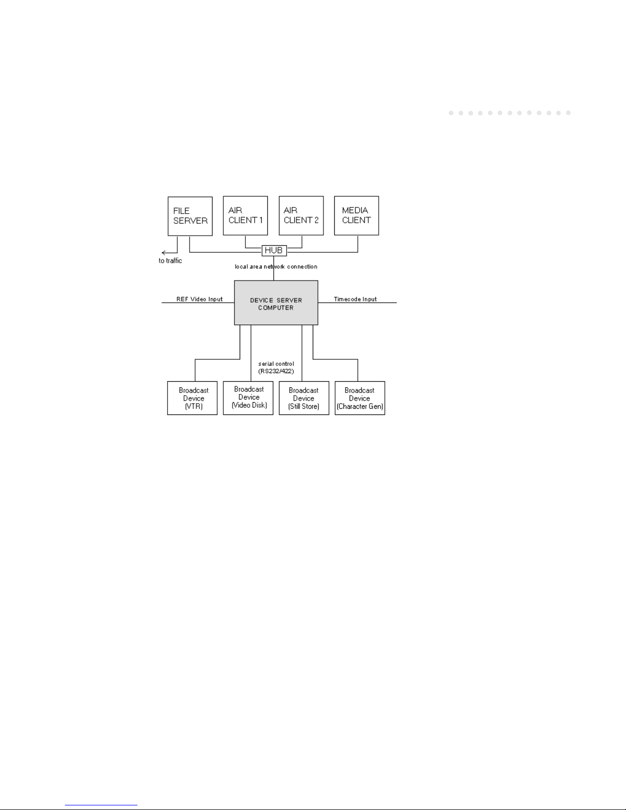
The following diagram presents a basic overview of automation system components:
Using Harris Automation in the Broadcast Environment
Three major activities are performed in the broadcast environment to prepare an event for air.
◆ The station’s Traffic department typically generates a dub list (new material to prepare for onair playout). Using the Harris Media Client (available separately), this list can be transformed
into a label list for barcode labels and the tape details directly entered into the Harris database,
as well as a dub list for spots to be entered into a video disk server.
◆ Tr af fi c p ro d uc es a s ch ed ul e o f th e i te ms t o be played out during a specific time period. The
automation system accepts the schedules from traffic through a traffic system interface, converts the schedules to playlists and stores the lists at the file server computer. Play lists can
also be created and edited directly from the client workstations.
To pr ep ar e a li s t f or p la yo ut , t he pl ay li s t i s l oa de d i nt o t he AD C D ev ic e S er ve r tr an s mi ss io n
window and becomes a transmission list. ADC Device Server activities are driven by
transmission lists. There are two major types of transmission lists – play and compile lists.
Play lists are used for both playout and record events, although separate lists are used for each
of these activities. Compile lists are used to take interstitial material and record it together on a
separate tape to be played out by a single VTR. Compilation reduces the number of VTRs
needed to play out the interstitial material to air.
Page 20

Harris ADC Device Server User’s Guide
4Introduction
◆ While a play list is running, each event performs a specific task such as play, record, which
includes threading and switching. After the event airs, the actual start time and duration of
the event are written in the As-Run log (file). This log is typically returned to Traffic where
changes in the original schedule can be compared and billing and recordkeeping updated.
System Components
The basic automation system is comprised of the following components:
◆ ADC Device Server
◆ Backup (Redundant) Server (suggested)
◆ Air Client Workstation(s)
◆ Media Client Workstation
◆ File Server
ADC Device Server
The ADC Device Server is the computer dedicated to communicating and controlling the
broadcast devices and client workstations. The device server is the subject of this manual. The
device server controls devices via an RS-422 connection. It also sends and receives frameaccurate information across the Local Area Network (LAN) from remote client workstations.
Backup (Redundant) Server
(Optional) Backup is an important part of automation. The ability to recover immediately
from hardware failure in a broadcast environment is crucial. Protection against device server
failure can be achieved through a backup (redundant) device server.
The backup device server is a computer which is identical to the main device server. If the
main device server fails, the backup device server takes over the tasks handled by the main
device server. The backup device server is configured the same way as the main device server.
If the main device server fails, the device connections can be manually transferred to the
backup device server. The transfer is accomplished by an RS-422 switching device.
Air Client Workstations
The Air Client workstations are PC computers that run client application software. The
workstations communicate with the Device Server through a local area network.
Page 21

Harris ADC Device Server User’s Guide
Introduction 5
The client workstations (and the control panels) are where users interact with the ADC Device
Server. A typical automation system comprises enough Air Client workstations to support
several users. At an Air Client workstation, a user creates and edits playlists. Users that have
the proper access rights can also control the transmission lists from the Air Client.
Hardware Control Panel
(Optional) The hardware control panel is a hardware device for controlling the playout of
transmission lists. The hardware control panel contains backlit buttons. While each button has
a specific function, buttons can be customized to meet specific needs. The Air Client supports
multiple control panels, which may be required in multichannel systems.
Media Client Workstation
The Media Client workstation is used to prepare material for air. Media Client uses the dub
list generated by Traffic. The operator then creates material records and writes the records to
the database.
File Server
The file server stores the database and play list files. Through the use of a client, commands
are sent to the file server. The file server then reports back to the client, at which time the client
sends commands to the device server for execution.
The file server does not run any software. Its sole function is to free the device server to
exclusively control devices. The device server reads the play list from the file server (via a
network hub), then executes the play list.
Additional Options
Av ai la bl e op ti on s in cl ud e:
◆ Additional Client (user) workstations
◆ Additional ADC Device Server devices
◆ Additional supported channels
◆ Additional control panels and customization of pushbutton functions
◆ GPI interface
◆ Media preparation
◆ Database conversion
Page 22

Harris ADC Device Server User’s Guide
6Introduction
◆ Tr af fi c i nt er fa ce
◆ Redundant device and database server (cloning)
◆ Redundant Device Server switch box
◆ ID/Title Mismatch software
◆ Air Protect
◆ Compilation
◆ Auto-record
◆ GMT
◆ Customization of other features
What is the ADC Device Server?
The device server is the heart of the automation system. The device server controls devices
through RS-422 connections and General Purpose Interface (GPI). The device server
communicates with remote clients through a Local Area Network (LAN) connection,
Physically, the ADC Device Server is either a 20-slot or 10-slot, rack mount PC. The device
server is installed with ADC Device Server software (which is different than what is installed
at the client computers). The server contains four-port serial boards (where the devices
connect), GPI boards, timecode reader board, reference video board and a network board. A
20-slot server installed with four-port serial boards can control a maximum of 64 devices and
provide 16 channels simultaneously. If more capacity is needed, additional device servers can
be added to the system.
The ADC Device Server is configured remotely from any client on the Harris automation
system containing the Remote Configuration Tool. The Configuration Tool contains common
Windows usability features, such as drag and drop and a point-and-click graphical interface.
The system is highly flexible and can be configured for most broadcast operations and
equipment. The ADC Device Server controls most types and models of broadcast devices,
including cart machines, video disk servers, external VTRs, still stores, character generators,
routers, switchers, distributors and master control switchers. The ADC Device Server can also
incorporate existing broadcast applications into the Harris system.
One of the ADC Device Server’s major strengths is its powerful software. The software
interfaces with and controls the broadcast devices (instead of hardware interface boxes). The
software can be easily modified to incorporate new models or types of devices.
Page 23

Harris ADC Device Server User’s Guide
Introduction 7
Automation system components (including the ADC Device Server) are connected through a
local area network (LAN), in a client-server configuration. The ADC Device Server integrates
the on-air playout system by using station reference video to maintain timing, by using station
timecode to keep to the on air schedule and by controlling virtually any serially-controlled
device (including satellite receivers), and any GPI (General Purpose Interface) controlled
device. The Master Control operator can control the on air playout from a Harris control panel
(similar to a Master Control Switcher Panel). The system can also be started automatically by
time of day, as well as remotely by GPI.
Features
Features provided by the Harris ADC Device Server include:
◆ Software-based System. Most automation systems use the SMPTE standard E/S
Bus to communicate and control broadcast devices. These systems use hardware
interface boxes between the E/S Bus and the devices. Modification or
customization of a system typically involves changes to the hardware, which can
be a difficult process. The ADC Device Server instead uses software tools (objects)
to communicate with broadcast devices in lieu of hardware interface boxes. With
the ADC Device Server, modification to the system is simpler and throughput is
faster.
◆ Object Oriented Programming. The ADC Device Server software is written using
a modern programming technique called object oriented programming (OOP).
With OOP, broadcast devices are treated as software modules or objects. Each
object can be easily modified and extended to support other makes and models of
devices within the same family. Development of custom software modules is
faster and more affordable.
◆ Real Time Control. The ADC Device Server provides frame accurate control.
◆ Future Proof. The Harris system is extendable to new devices, new applications
(for example, HDTV) and current applications (such as multichannel output,
video disk servers and compiling). The system is designed to fully support future
needs and requirements.
◆ Harris Application Programming Interface (API). Harris’ Application
Programming Interface (API) is software that creates a bridge between external
applications and the ADC Device Server. It allows external applications, such as a
newsroom system, or custom modules to seamlessly link to the devices. The API
allows system integrators or customers to develop applications that work directly
with the ADC Device Server.
◆ Client/Server Architecture. The ADC Device Server utilizes a versatile
implementation of client/server architecture. With this architecture, the workload
Page 24

Harris ADC Device Server User’s Guide
8Introduction
is distributed as needed. The Device Server computer performs real-time work
while the client computers are available for non-real-time work such as editing
playlists, media verification and as-run logging.
◆ Multi-user. The local area network architecture allows for almost any number of
users to access the ADC Device Server simultaneously.
◆ Automated Recording. Satellite or other feeds can be recorded through a record
list. An optional secondary record event allows for recording and segmenting of
live material for playback.
◆ Cart Machine Handling. ADC Device Server’s interface to cart machines is at the
lowest possible level. This allows for greater control of the resources and more
efficient operation. The interface displaces the cart machine’s operating system
and application and related hardware (which reduces the cost of using the cart
machine).
◆ Video Disk Expertise. The Harris disk protocol was introduced to be an industry
standard for controlling disk systems. The protocol has since been adopted by
companies such as Tektronix and Hewlett Packard. The protocol enables these
disk devices to be used as multi-channel cart machine replacements.
◆ Compilation. With the compilation feature, spots can be compiled onto a single
tape.
◆ Multiple Lists/List Types. The ADC Device Server can run up to sixteen lists at
the same time from one Device Server. The lists can be playlists running
independent channels or they can be a combination of play, compile and record
lists, media and GMT lists.
◆ Air Protect. The ADC Device Server supports the simultaneous playing of two
copies of media in two similar devices where one copy is an air copy and the other
a protect copy. This feature is used to protect program or commercial material on
tape, compiled tape or spot material recorded on duplicate video disk servers. A
failure detected by the ADC Device Server of the on air device results in the
automatic switching of the protect device to air. Operators have the ability to
manually switch the protect device to the air feed for such failures as head clogs
or audio/video problems.
◆ Windows NT® Operating System. The ADC Device Server runs on the Windows
NT operating system.
Broadcast Devices
The ADC Device Server is designed to interface to most devices commonly found in broadcast
operations. Such devices include:
Page 25

Harris ADC Device Server User’s Guide
Introduction 9
◆ cart machines
◆ video disk servers
◆ external VTRs (VTRs not in cart machines)
◆ routing switchers
◆ master control switchers
◆ still stores
◆ character generators
◆ audio carts
◆ external encoders and decoders
◆ subtitling systems
◆ satellite systems
RS422 connections are used between the Device Server and the broadcast devices.
Some broadcast devices do not interface to RS422. These devices can be controlled through
GPI-type connections with relay contacts.
Play Lists and Transmission Lists
Play lists are files that contain the schedules of events to be played, recorded or compiled. In a
play list, each event contains information such as start time, event type, material identification
(ID), title, segment number, duration, start of message and channel output.
Play lists can be created locally at the Air Client workstations or from traffic schedules. Play
lists are stored at the file server and are available to all users on the system for viewing and
editing. When a play list is ready for transmission, the list is loaded into the transmission
window and becomes a transmission list.
The ADC Device Server supports multiple transmission lists. Each list can contain 2,500
events by default (this number can be expanded to a larger number if necessary. Contact
Harris.).
When an event in the transmission list is activated, the event performs a predefined function
such as Play, Record, Switch or Cue. The ADC Device Server supports multiple transmission
lists; each list can be made up of several appended playlists.
Page 26

Harris ADC Device Server User’s Guide
10 Introduction
During configuration of the devices, each transmission list (transmission window) is assigned
specific broadcast devices. Devices are assigned to lists as resources. During playout of the
transmission list, the devices assigned to the list are available to run the events in the list. Each
transmission list controls a separate channel. This feature allows for simultaneous multichannel operations. In addition, cart machine VTRs can be assigned to two or more
transmission lists for two (or more) channel operations controlled by the one cart machine. Or,
the cart machine VTRs can be assigned different tasks. For example, two VTRs might be used
for playout, one for record, and one for compile. Video disk servers with multiple ports can be
shared between transmission lists.
The ADC Device Server plays each event in the list sequentialy until the operator intervenes
or specific types of events, such as live events or time-triggered events, are encountered. An
event runs according to where the event is located in the list or what time (if any) is entered for
the event. If changes to the list are needed during playout, the user can directly edit an event
in the list. (The only limitation on the time is the ability of the device to ready the material for
air; e.g., sufficient time is allowed for cueing and pre-roll of the edited event).
Playout can be controlled by the control panel (software or hardware). Using the control panel
buttons, it is possible to skip events, hold up the events past their EOM (end of message time),
and recue events and then restart them. An on-air event can also be edited by either adding or
subtracting a second to the event’s duration.
Automated Recording
An optional ADC Device Server record function provides for automated recording of material.
A recording can be set up for a specific date and time and set duration.
A record list is similar to a play list but just contains record events. Also like the playlist, the
record list is loaded into a transmission window to run the events in the list.
A secondary record event, also an ADC Device Server option, is available for recordings
scheduled for immediate play out. The secondary record event feature uses a playlist that has
both record and play events. This feature can store program segment information (for future
replay of a live event).
The ADC Device Server can use any VTR or video disk in the system for a recording. For long
VTR recordings that require several tapes or to create duplicate copies of a show, several VTRs
can be assigned. This also allows multiple recordings to take place simulultaneously using the
same list.
The ADC Device Server controls input audio and video switching when the recording begins.
Recordings can be made from program output or from external feeds, such as satellite.
Page 27

Harris ADC Device Server User’s Guide
Introduction 11
Harris’ AutoSat™ system is available to automate acquisition and recording of satellite
signals. AutoSat works as an integrated part of the Harris system, using a simple menu-driven
system. Contact your Harris representative for more information on AutoSat.
GMT
(Optional feature) Global Media Transfer (GMT) is Harris Automation's system for controlling
media movement within a broadcast facility. GMT works in conjunction with the on-air
automation system. Each transmission list may ask GMT to find media that cannot be found
in the devices assigned to the list. GMT finds and moves the media to a destination device
(usually a video disk server) assigned to the transmission list. The transmission list then airs
this media. The main tasks of GMT are:
1. Find media/material needed by an on-air transmission list.
2. Copy that media to a videodisk server serving that transmission list.
3. Monitor the movement of material.
4. Log the movement of material.
5. Provide automatic media duplication on multiple video disk servers for air protection.
By accomplishing these tasks, GMT extends the level of automation beyond the basic to-air
system. By moving the media handling to the automation system, less manual operator
intervention is required and better use of expensive videodisk server space is obtained.
Compilation
A group of spots or other interstitial material can be prerecorded together on a separate tape
(i.e., compiled) and then played out as a single item (rather than playing out each separately).
Each separate item of original material is logged in the asrun file as a separate entry.
With the compile feature, fewer tapes are required for playout of spots. The material is
recorded on the tape in playout order. The problems associated with locating and cueing
different spots placed on the same tape are avoided. Also, the quality of the playout material
can be checked when the spots are being recorded/compiled.
Page 28

Harris ADC Device Server User’s Guide
12 Introduction
Page 29

Harris ADC Device Server User’s Guide
1 Installation
The ADC Device Server consists of a server and a client, each with communication
software that allows the server and client to “talk” to each other. The software on each
must be configured in order to communicate properly. See “Configuration Manager”
on page 2-1 for details on how to configure the server and client.
System Requirements
The following are the minimum requirements to run Harris’ ADC Device Server
software.
Microsoft Windows NT 4.0 with Service Pack 4 or later
100 MHz CPU (133 MHz recommended)
32 MB RAM (64 MB recommended)
CD-ROM drive
100 Mb compatible network card
Installing the NT Device Drivers
Insert the floppy disk or CD-ROM containing drivers for the Harris NT Device Server.
This disk/CD-ROM is labeled:
NT DRIVERS
VERSION 1.01
1. Run Windows Explorer, then double click on the setup.exe file on the floppy. If using
a CD-ROM, the CD is self-starting.
2. Proceed through the various screens, at the end of which you will be prompted to
restart the computer. Select Finish to restart the computer. Make certain the floppy is
still in the drive when you select Restart. Remove the floppy after the system finishes
rebooting.
3. After restarting, select Start > Programs > Administrative Tools > Event Viewer to verify
which Harris NT driver services have been started. You should see a service for
TimeCode, HarrisSer, HarrisGPI, and VREFSync.
Page 30
Harris ADC Device Server User’s Guide
1-2 Installation
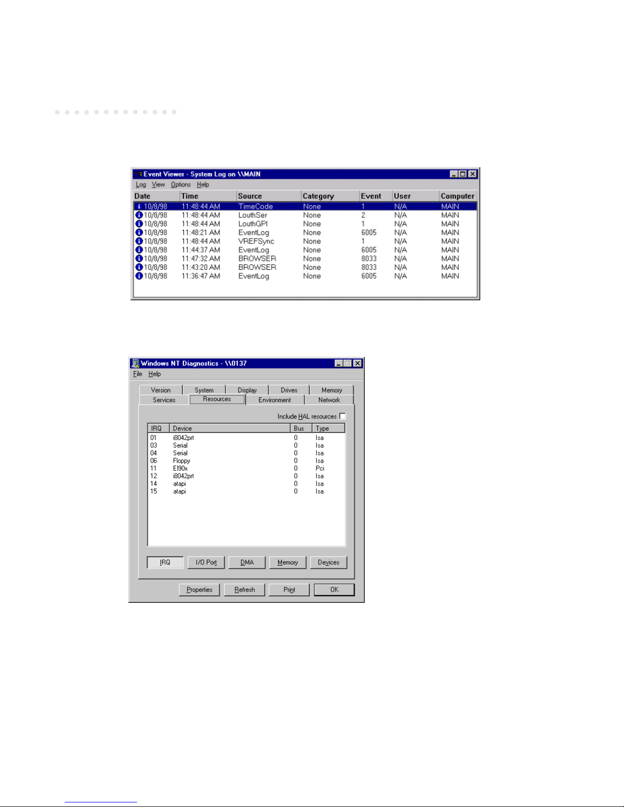
4. Select Start > Programs > Administrative Tools > Windows NT Diagnostics, then the Resources tab
can be used to check the IRQ and I/O settings used by these boards.
5. Make sure that the VREFSync driver is using interrupt 3 and that no other device is using this
interrupt. Make sure that TimeCode driver is using interrupt 5 and that no other device is
using this interrupt.
6. Selec the I/O Port button to display the input/output port usage:
Page 31

Harris ADC Device Server User’s Guide
Installation 1-3
7. Confirm that you see the HarrisSer for each four port serial card configured in the system.
Checkkey.exe
After installation is complete, a program file CHECKKEY.EXE is installed in the \SERVER
directory. Run this program to verify that it finds the VSYNC hardware.
Page 32

Harris ADC Device Server User’s Guide
1-4 Installation
The first box should have a check mark in it and all the other boxes should be blank. If any
other situation is present, the hardware has been misconfigured. Contact your Harris
representative for further assistance.
Installing the Server Software
NOTE: The Device Server software is installed on the device server. The Device
Server should be used exclusively as a device server, not running any
other applications. Harris’ software is designed to use all possible
resources on the device server, and performance deterioration will result
if the device server is used to run additional software.
You w il l ei the r hav e the s er ve r so ft wa re o n t wo f lo pp y d is ke tt es , or o n a n ele ct ro nic al ly delivered file titled server.exe. This is a self-extracting executable file containing all the files
necessary to install the server software.
To i ns ta l l th e De v ic e Se r ve r s of tw ar e, p er fo rm t he f ol lo w in g:
NOTE: If you already have the files on two floppy diskettes, skip to step 6.
1. Copy the server.exe file to a temporary directory. This file is a self-extracting zip file.
2. Open a command prompt and cd into the directory containing the server.exe file.
3. Ty p e server.exe -d to extract the file. The file extracts into two subdirectories, titled “Disk1”
and “Disk2.”
4. Copy the “Disk1” files onto a floppy diskette and label it “ADC NT Server Disk #1.”
5. Copy the “Disk2” files onto a floppy diskette and label it “ADC NT Server Disk #2.”
6. Go to the device server and insert Disk #1 into its floppy drive.
7. Open a command prompt and type a:setup.exe to begin the installation.
8. InstallShield proceeds to install the software onto the server. Follow the onscreen instructions
to complete the installation. The opening screen resembles the following:
Page 33

Harris ADC Device Server User’s Guide
Installation 1-5
9. Click Next to continue. One of the subsequent screens is worth mentioning here:
This screen does NOT appear if you are reinstalling the software. Only upon the first
installation on your server does this screen appear. If you wish to RENAME your server after
installation, you must make the change via the command line parameter. See “Command Line
Parameters” on page 1-7 for details on how to change the server name by changing the
command line parameter.
10. After installation is complete, store the installation floppies in a safe place.
Page 34

Harris ADC Device Server User’s Guide
1-6 Installation
Installing the Configuration Software
NOTE: The configuration software is installed on any client on the Harris
network, NOT on the device server. If you already have a floppy diskette
containing the files, skip to step 3.
1. Copy the config.exe file to a temporary directory. This file is a self-extracting zip file.
2. Copy the extracted files onto a floppy diskette and label it “ADC NT Configuration.”
3. Insert the floppy disk into the client’s floppy drive.
4. Open a command prompt and type a:setup.exe to begin the installation.
5. InstallShield proceeds to install the software onto the client. Follow the onscreen instructions
to complete the installation.
6. Enter a password when the following screen appears during installation:
Make sure to remember the password you enter. You will be required to re-type the same
password on the next screen to confirm your password choice. If you forget the password or if
it becomes compromised (i.e., the proper password no longer works), you must re-install the
configuration utility.
CAUTION! After installation is complete, store the floppy disks in a safe place. If
you installed from a temporary directory on your hard drive, make
sure to delete the temporary directory. If these files are left on the
computer, anyone can override the password by simply reinstalling
the configuration software and entering a new password.
Page 35

Harris ADC Device Server User’s Guide
Installation 1-7
This password may be changed at any time from within the configuration utility. See
“Changing the Password” on page 2-23 for details on how to change the password.
Proceed to “Configuration Manager” on page 2-1 to configure the client for use.
Command Line Parameters
The configuration installation program creates a desktop shortcut containing the executable
filename plus a command line parameter. Example:
C:\CONFIG\ADCNTCFG.exe NTCONFIG
The NTCONFIG parameter indicates the name of the client running the configuration utility.
This name must be unique on the Harris network. If the configuration utility is installed on
more than one client, each client must have a unique name.
The device server installation also creates a desktop shortcut containing a command line
parameter. Example:
C:\SERVER\adc100nt.exe MAIN
The MAIN parameter is the default name given to the device server. This name must be
unique on the Harris network. We recommend you change this name to something different,
to ensure that no two servers have the same name.
Command line parameters are limited to 16 characters.
Upgrading from DOS to NT
NOTE: This section applies only if you are upgrading from Harris’ ADC100 DOS Server
to the ADC Device Server. If you are a new user, skip this section.
1. When copying the .ini files from a DOS ADC100 server to an ADC Device Server, copy the
files ADC100.INI to LISTCONF.INI and ADC100NT.INI. From a command prompt, type:
copy ADC100.INI LISTCONF.INI
copy ADC100.INI ADC100NT.INI
Page 36

Harris ADC Device Server User’s Guide
1-8 Installation
The legacy DOS .ini files do not contain the serial port configurations. In the ADC Device
Server, each serial device can be assigned to use any valid serial port. The advantage to this is
that if a serial card or port is suspected to be bad, the device can use another port without
having to reconfigure the device or any associated switching.
Make sure to configure each serial port after the server is brought up.
2. The ADC Device Server supports extended device names. A device name may now be 16
characters long. This allows device names in large systems to be more informative (you can
still use 5 character names if you wish). To use the extended device names, enter them into the
device name field of the properties for the device being configured.
In order for the Air Client to use extended device names, the Air Client must be run with a
command line switch of /NT:
ACLNT32 clientname main backup /NT
3. On the ADC Device Server, list names (play lists, media lists, GMT lists, and compile lists) can
be set for each list. These names can be used in the Air Client without having to configure the
list names for each Air Client. In order for the Air Client to use them the Air Client must be
run with a /NT command line switch. Using the /NT command line switch causes the Air
Client to read the list name from the ADC Device Server. Using list names on the Air Client
does not disable the listname property for configuration. As a result, do not use list names on
the Air Client if you are using the /NT option. This way, the Air Client inherits the list name
from the device server.
ACLNT32 clientname main backup /NT
4. Yo u mu st c on fi gu re yo ur s wi tc he rs b ef or e se tt in g up a ny a ud io /v id eo ( A/ V ) in fo rm at io n i n
any of the devices. This includes naming the switcher and entering a crosspoint name for each
usable source and destination.
5. The audio/video information is now configured under the list configurations (i.e., the A/V
paths for a device are configured on each list that might use the device). This is because the
information pertains to the switching for that list. The A/V information is still stored in the
device part of the ini files.
6. The audio/video information for the preview channel is now stored as list number 17. In the
DOS Server, the preview channel was always stored in the device under the last list plus one
(if the server had 6 lists the preview, A/V information was stored as list 7). If you ever added a
list to the server the preview A/V information had to be reconfigured. This is not true in the
NT version.
When converting a DOS .ini file to an NT .ini file, you must reconfigure the preview A/V
information or edit the ADC100NT.INI file to change the preview A/V information for each
device.
Page 37

Harris ADC Device Server User’s Guide
Installation 1-9
7. The ADC Device Server only runs on the Harris 4-Port Serial Cards.
8. The SONY LMS object does not have the router built in anymore. Instead, a new device under
routers exits.
◆ Configure the LMS device first.
◆ Configure the LMS Router under Router/Switchers.
◆ Invoke the Properties form for the LMS Router and select the Cart Machine page.
Configure the LMS Router to use the correct cart machine. The Enable Switcher
Monitor only applies to Beta Carts that have the monitoring built in.
9. The Help > About Server menu on the Device Configuration and List Configuration screens
display the server name and version number of the server software. To display the version
number of the Configuration Manager, use the Help > About menu option (in the first screen of
the configuration program).
10. Sometimes if the NT Server generates a runtime error and you restart it, it may still be
running. If this appears to happen, invoke the Task Manager and see if a copy of
ADC100NT.EXE is already running. If it is, terminate that process before running
ADC100NT.EXE again.
11. There is no manual VTR mode in any of the Odetics cart machines under NT. The architecture
of these machines under NT prohibits this function.
12. The Standard Video Disk drivers and Profile drivers treat the two heads as one video stream
under NT. When assigning the STREAM to a list, both heads are moved as one pair. When
configuring Audio/Video this is also done on the STREAM so that you only have to configure
the STREAM once (but both heads will be automatically configured).
13. Some devices have not been ported to NT. These devices had been replaced in DOS with
newer device drivers. Only the newer device drivers are available under NT.
Page 38

Harris ADC Device Server User’s Guide
1-10 Installation
Tab le 1 -1 U pd at ed N T Dri ve rs
OLD DRIVER NAME
NEW DRIVER NAME
GVG Master 21 MCS GVG Master 21
Thomson 9920 Thomson 9920 MCS
Probel System 2/3 Pro-Bel System 2L
Probel System 2/3 Pro-Bel System 3L
Oxtel ImageStore Keyer Only Oxtel ImageStore
Page 39

Harris ADC Device Server User’s Guide
2 Configuration Manager
The ADC Device Server is configured remotely from a client on the Harris automation
network running the server configuration software. We call the remote client utility
the Configuration Manager throughout this manual.
Configuring the Device Server
The only configuration setting on the device server is the server handle. It may be left
blank, then configured from the Configuration Manager (next page). It must be a
unique number not assigned to any other device server on the Harris Automation
network. The other configuration options (devices and lists) are remotely configured
from any client on the Harris network that has the server configuration software
loaded.
Launch the server application. Click File > Server Handle.
NOTE: The Server Handle can be configured remotely from the configuration
Manager if you desire.
File Menu (Server)
Server Handle
Choose a unique server handle. The server handle is used by the Harris automation
system to distinguish different automation system components. Each component
must have a unique handle.
Page 40

Harris ADC Device Server User’s Guide
2-2 Configuration Manager
View Menu (Server)
Connections
Click View > Connections to see a list of connected servers.
The remainder of the configuration options are found in the Configuration Manager (discussed
next).
NOTE: The remaining options are found in the configuration software, installed on a
client. The configuration software should NOT be installed on the device server,
as performance degradation will result.
Configuration Manager
NOTE: If using more than one Configuration Manager to configure the server,
make sure that only one is running at a time.
The Configuration Manager is an integral part of the Harris ADC Device Server, running on any
client on the Harris Automation network. Do not run the Configuration Manager on the
device server. Running the Configuration Manager on a client benefits the mission-critical
device server by freeing up valuable CPU time for the server.
Launch the Configuration
Manager.
Enter your password to gain
access to the Configuration
Manager. The password must
be between 1 and 16 characters,
and may include letters and
numbers. See “Changing the
Password” on page 2-23 for
details on creating and/or changing your password. The password was created when you ran
the installation program.
A screen similar to the next follows:
Page 41

Harris ADC Device Server User’s Guide
Configuration Manager 2-3
Click on the server to select it.
Server Handle
Right-click on the highlighted server, then select File > Server Handle from the menu. If you
entered a server handle in the server, you do not need to repeat it again here.
Configuring Devices
Right click on the configured device, then choose Configured Devices. The following screen
appears:
Figure 2-1 Configured Devices (1 of 2)
Page 42

Harris ADC Device Server User’s Guide
2-4 Configuration Manager
Drag a video disk server to channel 1:
1. Click the plus sign (+) to the left of Video Disk Servers to expand the list.
2. Click on the device to be configured to highlight it.
3. Drag the highlighted item over to the left side, and drop it anywhere on the Channel 1 line.
The device is now configured as Channel 1:
Figure 2-2 Configured Devices (2 of 2)
Note that the number of Video Disk Servers available on the right side has decreased from 4 to
3, since one of the 4 available servers in our example has now been configured.
4. Right-click on the configured device in the left column, then choose Properties. A dialog box
with multiple configuration options appears. Use the left and right arrows in the upper right
corner to scroll through the other tabs (some devices can have 10 or more tabs).
5. Yo u ma y wa nt t o re nam e th e de vi ce . Fo r ex am pl e, th e ab ov e De mo Vid eo D is k ha s a d ef aul t
name of “DDsk.” If this is to be used as an air disk, you could rename “DDsk” to “Air.” This is
done by typing in a new Device Name in the General tab. Right-click on the device and select
Properties to access this tab.
Page 43

Harris ADC Device Server User’s Guide
Configuration Manager 2-5
Figure 2-3 Device Configuration Properties
NOTE: The above example is generic and meant for demonstration purposes only. The
steps to access the configuration options are the same, regardless of the device;
however, the individual options and tabs will vary depending on the device and
make/model. Refer to the User Notes for your device for complete details on how
to configure it.
Repeat steps 1-4 above for all devices to be configured. Once your devices are configured, they
are ready to be added to lists.
Logically Configuring Your Devices
The Harris automation system checks for material on play lists with configured devices in
channel order (Channel 1, Channel 2, Channel 3, and so on, in order). Real devices should be
configured on the lower channels, with virtual devices (requesters, distributors, and switchonly devices) configured on the higher channels. (“Virtual” devices are in actuality
programming code used by the automation system to process commands, whereas “real”
devices are physical devices that connect to the device server via an RS-422 cable.)
We re co m me nd t ha t yo u c on f ig u re V TR s an d v id e o d is k s f ir st , t he n ot he r p hy si ca l (r ea l)
devices and lastly cart machines. Virtual devices such as requesters and distributors should be
configured in unused channels, after all physical ports.
Deleting Devices
To d el et e a c on fi gu re d de vi ce , d o th e f ol lo w in g:
Page 44

Harris ADC Device Server User’s Guide
2-6 Configuration Manager
1. Display the configured devices (see Figure 2-2 on page 2-4).
2. Drag a device from the left side to the right side to delete it (from the Configured pane to the
Av ai la bl e pa n e) . A co nf ir ma ti on b o x ap pe ar s asking if you wish to delete the device.
3. Click OK to delete the device and return it to the list of available devices.
NOTE: If you delete a configured cart machine, the cart machine ejects tapes from VTRs
and returns the tapes to their locations in the bins. As a result, a slight delay in
deleting the cart machine may occur. The server eventually removes the device
from its list of configured devices, with no further operator intervention required.
Configuring Lists
After devices have been configured, they may be assigned to a list. A list of available devices
appears, based on what devices were configured earlier. See “Configuring Devices” on page 23 for details on how to configure devices.
Four types of lists are available to choose from:
Play list. Sends commands from play list data files to air devices. Assign devices to Play
List for on-air playout.
Media list. Sends commands generated by Media Client to media preparation devices, such
as VTRs, video disks, and cart machines. Assigning devices to Media List makes the device
available exclusively to Media Client.
GMT list. Executes commands to and from GMT components. Only GMT components
should be assigned to GMT List, as they will be unavailable to other lists.
Compile list. Use a compile list to combine several spots onto one tape. This reduces the
number of devices required during playout. Without compilation, each spot is recorded
onto a separate tape and each tape requires a separate playout device.
To c on fi g ur e a l is t , do t h e fo l lo wi ng :
1. Right click on the server, then select List Configurations (selecting File, List Configurations also
accesses the same dialog box, similar to the following:)
Page 45

Harris ADC Device Server User’s Guide
Configuration Manager 2-7
Figure 2-4 List Assignments (1 of 2)
Note the names “Air” and “Protect” appear as available media. This is because we renamed
“Ddsk” to “Air” and another demo video disk to “Protect” for demonstration purposes.
2. Drag “Air” from the right side onto PlayList 1 on the left side, then drop it onto PlayList 1.
You r sc re en sh ou ld r es em bl e th e fo ll ow ing :
Figure 2-5 List Assignments (2 of 2)
3. The first video disk has now been assigned to PlayList 1. Repeat this procedure for all
configured devices. Once a device has been assigned to a list, that device is exclusive to that
Page 46

Harris ADC Device Server User’s Guide
2-8 Configuration Manager
list, and cannot be shared by another list. The only exception to this rule is a video disk with
multiple streams. Each stream of a video disk can be assigned to a different list, thereby
allowing multiple lists to share the same video disk. Example: The record stream could be
assigned to a media list, and the playout stream assigned to the play list.
Configuring a Protect Device
A protect device (also known as an air protect device) is a duplicate device that runs in
parallel with the air device. Typically a video disk, the protect disk plays out the identical
material as the air disk, ready to step in if the air disk crashes. In this event, the air protect disk
is broadcast.
The protect device automatically replaces the air device in the event that the air device loses its
connection with the server.
If the operator notices a problem with the air device (such as poor picture quality) and wishes
to manually switch to the protect device, this can be done by using Harris Automation’s Air
Client. See the Air Client User’s Guide for details on how to manually switch to the protect
device.
To c on f ig ure a pr ot e ct de vi ce , d o t he fo ll ow i ng (o ur ex am pl e u se s t wo vi d eo di sk s; o ne as an
air disk and one as a protect disk):
Make sure you have configured at least two video disks. See Figure 2-2 on page 2-4 for details
on how to configure a device.
1. Access the List Assignments dialog box again (highlight the server, then select File > List
Configurations or right-click, then select List Configurations).
2. Drag a second video disk from the Available Media (on the right side) directly onto the first
video disk. In our example, the resulting display looks like this:
Page 47

Harris ADC Device Server User’s Guide
Configuration Manager 2-9
Figure 2-6 Configuring a Protect Disk
The second disk is automatically configured as an air protect disk. The resulting display is
similar to the following:
Note the word Protect in parentheses listed after the second video disk. This indicates that the
protect disk was successfully configured onto the playlist.
If you accidentally dropped the second video disk on PlayList 1 instead of Air (the video disk
assigned to PlayList 1), it will appear like this:
Figure 2-7 Configuring a Protect Disk (wrong)
Page 48

Harris ADC Device Server User’s Guide
2-10 Configuration Manager
In Figure 2-7, the second video disk is not a protect disk (notice the word Protect does not
appear in parentheses). To undo this, right-click on the second disk, then choose Unsassign.
This action unassigns the second disk and moves it back to Available Media on the right side.
To v er i fy t h at t he p ro te c t di s k is c or re ct ly c on fi g ur ed , m ak e s ur e i t ap pe ar s in de nt ed u nd er t he
air disk, and not flush left with the air disk. Examine Figures 2-6 (right) and 2-7 (wrong) to see
the difference.
Play List Parameters
Parameters Tab
Name: Enter a name for the playlist.
Options
Rewind Spots: After a spot plays, the automation system rewinds the tape before ejecting it
from the VTR. The tape is rewound to the SOM minus the preroll (on a multi-spot tape,
the tape is rewound to the SOM minus the preroll of the last spot played). Default is
enabled.
Rewind to First Program Segment: After a program plays, the automation system rewinds
the tape to the first segment before ejecting it from the VTR. The tape is rewound to the
SOM of the first segment minus the preroll. Default is disabled.
Page 49

Harris ADC Device Server User’s Guide
Configuration Manager 2-11
Rewind Compile Material: After the final spot on a compile tape plays, the automation
system rewinds the tape before ejecting it from the VTR. The tape is rewound to the first
commercial break (or “pod”) minus the preroll. Default is disabled.
Extended Time to Next: The Time to Next functionality has been enhanced on a transmission
play list. Default is enabled.
The major Time to Next enhancements are:
◆ When the termination event is an O (hard start) event the Time To Next display
includes the running short value.
◆ Zero duration up counters no longer stop the rippling.
◆ When in an up counter, if an O event exists as the termination event, the Time To
Next computation computes without any long or short value. It displays exactly
how long until the hard timed start begins.
Thread Limited: A new list configuration, Thread Limited is available for controlling
threading on a list. By enabling the Thread Limited option, non-threaded but blue
(registered) events count toward the total thread time as if they were threaded. Default is
disabled.
Auto Restart When Cued: Allows a missing event to automatically start when cued. If
disabled, the automation system marks the event as missing and does not automatically
cue the event when located. Default is disabled.
Time Parameters
Preroll Seconds: Define the number of preroll seconds to be used for the selected list. The
valid range is 0-59 seconds. Default is 3 seconds.
Preroll Frames: Define the number of preroll frames to be used for the selected list. The
valid range is 0-29 frames. Default is 0.
Postroll Seconds: Define a length of time, in seconds, the automation system plays the
current event beyond its duration if it has not yet switched to the next event. The valid
range is 0-59 seconds. Default is 1 second.
Postroll Frames: Define a length of time, in frames, the automation system plays the current
event beyond its duration if it has not yet switched to the next event. The valid range is 029 frames. Default is 0.
StandbyOn Seconds: The amount of time the automation system keeps the VTR in tension
after cueing an event. The valid range is 10-59 seconds. Default is 30 seconds.
Page 50

Harris ADC Device Server User’s Guide
2-12 Configuration Manager
Options Tab
Options
Switch to Black: Switches to black on the output channel whenever the lists stops. Default is
enabled.
Play Hard Hits: Enables a hard start event to be started by an operator pressing the play
button on the Control Panel. When disabled, an operator is unable to start a hard start
event unless they clear the hard start type. Default is disabled.
COntact Start: Enables the Transmission list to be started by a GPI (General Purpose
Interface) contact. The GPI contact is equivalent to selecting Play on the Control Panel.
Playlists 1 through 16 correspond to contacts 1 to 8 of Card One/Two, respectively.
Default is disabled.
Auto A-B Routing: Overrides an event’s channel settings (displayed in Transmission
window's CH column in Air Client). During transmission, successive primary events are
routed alternatively through switching channels A and B. This function is useful to ensure
that two successive events are not played through the same channel (which is needed
when transition effects such as mixes are defined between events). Make sure both A and
B channel A/V parameters are configured in all devices that are used. Default is disabled.
Play ID Title Mismatches: (Optional feature) Allows mismatched events to play. Default is
enabled.
Page 51

Harris ADC Device Server User’s Guide
Configuration Manager 2-13
Skip Bad Events: Enables the list to skip bad events. A “bad” event is an event that is
unable to play, such as unavailable media or an event that causes an error during
transmission (due to a tape jam or tape running short, etc.). If consecutive bad events are
encountered, only the first bad event is skipped. In order to skip the following events you
must use the Play button in the Control Panel. If this option is disabled, the list stops
running when a bad event is encountered. To restart the list if this occurs, cut the bad
event from the list and press Play. Default is enabled.
Station ID On Skip: When this option is enabled and a Skip command is issued, the system
automatically switches to the Logo input (the Logo input is configured in the Device Server
through the switcher’s device parameters. Default is disabled.
Release Tension When Cued: Places tape events into tension release when they are cued. The
events are readied at the Standby On time before they are due to roll. Default is disabled.
Timed List: Enables the list to play Hard Start events at their specified start times. Default
is enabled.
Update On-Air Time: Aafter each event plays, the system updates the event’s time to the
actual time that the event was transmitted. This information is also written to the As-Run
Log (if logging is enabled). Default is enabled.
Auto Ripple Times: The system recalculates the projected start times for the events in the list
dynamically during playout (up to the first hard start event encountered) and updates the
event times accordingly. The calculation assumes that the Duration field for up-counting
events is accurately set. Default is disabled.
Te n s i on A f t e r U p C o u n t er : The next Standby On time (in seconds) worth of events that
follow an up-count event are tensioned on. If this option is disabled, the events are tension
released and the next event may only be tensioned on manually by pressing Ready in the
Control Panel. Default is disabled.
Thread After Break: Controls whether or not events are threaded following a break. If this
parameter is disabled, no events are threaded after the break. The events must then be
individually threaded once the list reaches the break, or the Program Run button must be
pressed after the break event is reached. Default is enabled.
Keep List Threaded: This option keeps as many devices threaded as possible, at all times. If
an event is inserted into the list to be played, the event is immediately cued and
subsequent events unthreaded as necessary. When enabled, thread time is not used.
When disabled, events are cued only within the thread times. Default is disabled.
Page 52

Harris ADC Device Server User’s Guide
2-14 Configuration Manager
Done Count
The number of completed events that display in the Transmission List window on the Air
Client. The valid range is from 1 to 20 events. Default is 4 events.
Thread Time
The amount of time a cart machine loads and threads a tape in a VTR prior to its
scheduled on-air time. The valid range is from 0 to 23:59:59:29 (23 hours, 59 minutes, 59
seconds, and 29 frames). Default is 2 minutes. If the Keep List Threaded box is enabled, that
setting overrides the Thread Time setting here.
Lookahead Tab
Duration Based Lookahead
Duration Based Lookahead: The Lookahead window is the area of the play list where the
automation system checks for event errors, missing media, and other possible problems.
To ba se th e l oo k ah ea d o n a ti m e d ur a ti on (s uc h a s 4 h ou rs , f or ex am pl e) , c he ck th i s b ox .
Default is disabled. When this option is left disabled, the Count Lookahead box to the right
is used by the automation system.
Hours: Specify a time duration, in hours, for the lookahead window to check. The
valid range is 0 to 23 hours. Default is 4 hours. This option has no effect unless the
Duration Based Lookahead box is enabled.
Page 53

Harris ADC Device Server User’s Guide
Configuration Manager 2-15
Minutes: Specify a time duration, in minutes, for the lookahead window to check. The
valid range is 0 to 59 minutes. Default is 0. This option has no effect unless the
Duration Based Lookahead box is enabled.
Duration Based Lookahead Toggle
When the Duration Based Lookahead box (above) is enabled, enabling the Duration Based
Lookahead Toggle allows the operator to hit the F8 key to toggle back and forth between the
setting chosen above and either an alternate time or the full list.
Enable Toggle Lookahead: Check this box to enable. This setting has no effect unless the
Duration Based Lookahead box is enabled (above). EnablingDefault is disabled.
To g g l e H o u r s : Set an alternate time for toggling back and forth from the default setting
chosen above. Use the F8 key to toggle back and forth between the default time setting
and the alternate time chosen here. The valid range is from 0 to 23 hours. Default is 4
hours.
To g g l e M i n u t e s : Set an alternate time for toggling back and forth from the default
setting chosen above. Use the F8 key to toggle back and forth between the default time
setting and the alternate time chosen here. The valid range is from 0 to 59 minutes.
Default is 0.
To g g l e t o A l te r n a t e T i m e: Select this option to cause the F8 key to toggle between the
Duration Based Lookahead setting and the alternate time set in the To g gl e H ou r s and
To g g l e M i n u t e s box to the right.
To g g l e t o F u l l Li s t : Select this option to cause the F8 key to toggle between the Duration
Based Lookahead setting and the full list.
Count Lookahead
Look Ahead: Select how many events the lookahead should check. Default is 50 events. If
Duration Based Lookahead (above) is enabled, that setting overrides the setting here in Count
Lookahead. Otherwise, this setting is used. Default is 50 events.
Events to Log Tab
NOTE: For a detailed explanation of the following options, please see the Air Client user’s
guide. Following is a brief description of each of the following options:
Page 54

Harris ADC Device Server User’s Guide
2-16 Configuration Manager
Secondary Events to Log
GPI Contact: Inserts a GPI contact closure secondary event to the list. For each event, an on
time (offset) and duration value must be entered. An offset indicates how long after the
start of the primary event the contact closure should occur. The duration value sets the
duration of the pulse or length of closure of the contact. The offset is entered in the event’s
on-air field and duration in the DUR field. The GPI closure may be longer than the
associated primary event. Default is enabled.
Back Timed GPI: Backtimed GPI is similar to a standard GPI event, except that the offset is
measured backwards in time from the start of the associated primary event. For example,
a backtimed GPI event with an offset of 5 seconds fires the GPI contact 5 seconds before
the start of the associated primary event. A backtimed GPI event cannot be attached to an
event following a primary upcount event. In this case, the system would not be able to
calculate when to begin the GPI event. Default is enabled.
Sec. Audio/Video: Secondary Audio/Video event; plays material, in addition to the primary
event on air, for use in effects such as keys, audio overs and mixes. Default is enabled.
Back Timed Sec. Audio/Video: Same as Sec. Audio/Video except the secondary’s on-air time is
the amount of time before the primary event begins. In the event Type field, these events
are inserted with types P and T (but not A). No switching is done on these events unless
this is changed. These events can be used as a key/audio over inputs to a master control
switcher. Default is enabled.
Page 55

Harris ADC Device Server User’s Guide
Configuration Manager 2-17
Keyer On/Off: Allows events to have an offset from the beginning of the event to be
specified. Define a secondary Keyer event in which a hole is cut in the associated primary
event’s video output and is filled with the output of the Keyer source. Default is disabled.
Transition Key: Similar to Keyer On/Off (above), except that the keyer is brought up at the
start of its associated primary event with the same transition type. This type of secondary
event has a configuration dialog box similar to Keyer On/Off; however, for the transition
key, the value of the offset cannot be set. It is possible to define a transition key event so it
lasts as long as the primary event. To do this, make the duration field blank. If the key
hold option is on, the key is held over the transition in the same way as an ordinary
secondary keyer event. Default is disabled.
Audio Over On/Off: The Audio Over secondary event is used to add another audio source
over the primary audio/video source. The audio over source may replace the primary
audio source or be mixed with it. Default is disabled.
Tr a n s i ti o n A u d i o O ve r : Allows you to specify a secondary audio event to coincide with the
primary event in the same manner as a transition keyer event, as described in Keyer On/Off
(above). This event has a set of options that are identical to the audio over on/off
secondary event, except that the ontime option is missing (the ontime for a transition
audio over event is set to 0). In order to have the secondary audio event end at the same
time as its primary event, make the duration field blank. Default is disabled.
Data Event: This type of secondary event is associated with a device but does not generate
any video output. Instead, the action specified by the event is performed at the time the
event would be put on air, had the event been associated with a video device.
For video disk servers, a data event is used to control and automate the deletion of spots
from the server. The use of this event with video disk servers requires an accurate
scheduler or traffic program. If the events are not used carefully, spots may be accidentally
deleted in the video disk server. Secondary data events are used to command serial
devices requiring a simple command that does not need to run a countdown on the time
of an event. Default is enabled.
Barter Spot: Barter spot events are associated with a primary event and are logged to the
asrun log when the primary event runs to completion and is logged. Barter spot events are
treated as comments by the automation system and are not played. Default is disabled.
Record Switcher: A secondary event that performs extra switching for inputs. During a
recording, this switches to the secondary event’s source. The name of the source to switch
to is entered in the title field. This name must also be in the source name table for the
switcher that is supplying the video to the record device.
Page 56

Harris ADC Device Server User’s Guide
2-18 Configuration Manager
The event is only performed if the primary event’s device has the A/V data parameters
configured to specify the switcher number that has the matching name in its source name
table. Default is disabled.
Switcher Cross Point: This is a secondary event that performs extra switching for outputs.
While an event plays, this function switches to the secondary event’s source:destination.
This type of secondary event allows the control of multiple crosspoints during one
primary event. Default is disabled.
Secondary Record: This type of secondary event allows for the automatic recording and
segmenting of live program material for immediate playback to air. Unlike most record
events, this event is used in a list that combines record and playback activities. A
secondary record event is attached to each primary event that is being recorded. Default is
enabled.
Break Sync: Break sync contains an estimated time of day a pod will run, a deviation time
and a time for a window of opportunity for the operator to react to the event.
This event is normally used on a list that contains only pods/breaks of commericals. The
pods are separated by either an upcount event or by this Break sync event. The pods are
triggered to run by an external contact closure (GPI) or by clicking Play on the control
panel. In normal operation, a contact closure/play button is detected and the next pod on
the list is played. The break sync event is marked DONE immediately. The pod plays out
until either an upcount event, break sync event or the end of the list is encountered.
Default is enabled.
Comment: Use this secondary event to enter notes into the playlist. Comments are ignored
during transmission. Any text may be inserted into the title field of a comment. Default is
disabled.
System Event: Allows the traffic system to schedule device (resource) assignments during
the execution of a transmission list. Like all secondary events, this type of event is
attached to a primary event. When this event type is run, it is able to move unowned
device heads to the list running this event or release device heads in order to make them
available to another list. It is up to the traffic department to schedule the assignment and
release of heads so that two lists will not conflict in their usage of these heads. Default is
enabled.
Back Timed System Event: Works in the same manner as secondary system except that this
event type runs prior to the primary event by the time specified in the Time field. Default
is enabled.
Page 57

Harris ADC Device Server User’s Guide
Configuration Manager 2-19
Mix/Wipe Tab
Enable Mix/Wipe Support
Play Mixes/Wipes Early: Causes the list to pull back any events with the effect type of Mix,
Wipe, or Mixed Transition.
A Wipe effect requires a Wipe number. Each brand of Master Control Switcher may have
its own set of Wipes. Each event can have its own wipe number. These are displayed and
edited in Effect Number # field in the playlist editors of the Air Client. When the event is
played, the Wipe number in the event is passed to the switcher when the Wipe transition
is started. The Wipe number is solely dependent on the Master Control Switcher being
used and is not interpreted by the automation as anything but a number. Default is
disabled.
Effect durations in frames
Set the frame values for slow, medium, and fast effect durations. Effect durations are the
amount of overlap time between the end of one spot and the beginning of the next spot.
Slow: Valid numbers are 0 to 999 frames. Default is 60 frames.
Medium: Valid numbers are 0 to 999 frames. Default is 30 frames.
Fast: Valid numbers are 0 to 999 frames. Default is 15 frames.
Page 58

Harris ADC Device Server User’s Guide
2-20 Configuration Manager
NOTE: The effect duration settings must match the switcher’s settings on certain
switchers. Refer to your switcher ’s user manual.
Linking Tab
Master List Links
List is Master: For linked lists where the sectional lists must be complete (i.e., have all spots
that are on the primary list, with the exceptions). Default is disabled.
List is Keyed Master: Use this option when the secitonal lists are sparse and the exceptions
have keys to control them when they run. Default is disabled.
To l in k a li st , s el e ct a l is t f ro m t he Available column, then click the Add to <– button to move it
to the Linked column. List is Master and List is Keyed Master have no effect if no list is selected as
a linked list.
Media List Parameters
Parameters Tab
See the Play List “Parameters Tab” on page 2-10.
Page 59

Harris ADC Device Server User’s Guide
Configuration Manager 2-21
Options Tab
See the Play List “Options Tab” on page 2-12.
Events to Log Tab
See the Play List “Events to Log Tab” on page 2-15.
GMT List Parameters
Parameters Tab
See the Play List “Parameters Tab” on page 2-10.
Options Tab
See the Play List “Options Tab” on page 2-12.
Events to Log Tab
See the Play List “Events to Log Tab” on page 2-15.
Compile List Parameters
Parameters Tab
See the Play List “Parameters Tab” on page 2-10.
Options Tab
See the Play List “Options Tab” on page 2-12.
Lookahead Tab
See “Count Lookahead” on page 2-15 under the Play List Lookahead tab.
Page 60

Harris ADC Device Server User’s Guide
2-22 Configuration Manager
Events to Log Tab
See the Play List “Events to Log Tab” on page 2-15.
Compiler Tab
Options
Skip Missing Material: The compiler leaves space for events in a pod that are not currently
available to be compiled. It then continues to compile the pod around the missing
material. If you enable this option and then later change the duration of any of the missing
items of material you will have to recompile the remainder of the pod after the event
whose duration changed. Default is disabled.
Log Errors: Check this box to cause all compile errors to be recorded into a logfile. Default
is disabled.
Time Parameters
SOM: Specify a Start Of Message (SOM) value for the compile tape. Default is 00:01:00:00.
Ta p e L en g t h : This is the duration of the compile tape. Default is 01:30:00:00.
Break Gap: The distance between the end of black on one pod and the start of black on the
next pod. Default is 00:30:00:00.
Page 61

Harris ADC Device Server User’s Guide
Configuration Manager 2-23
Black In: The amount of pre-black to record on the tape before recording the first compiled
event. Default is 00:00:00:00.
Black Out: The amount of post-black to record on the tape after recording the last event in
a compiled pod. Default is 00:00:00:00.
Changing the Password
The password can be changed at any time from within the Configuration Manager. The only
requirement is that each password must be a minimum of one character and a maximum of 16
characters.
◆ Letters, numbers, and spaces are permitted.
◆ No special characters are allowed.
◆ The password is case sensitive.
To c ha ng e th e p as sw or d, d o th e fo ll ow in g :
1. Select File | Change Password. The following dialog box appears:
2. Enter a new password, then confirm it in the second box.
NOTE: The password displays as a series of asterisks on the screen for security purposes.
The password is stored in encrypted form in the system registry.
3. Click OK when finished.
Upon next launch, enter the new password to gain access.
Page 62

Harris ADC Device Server User’s Guide
2-24 Configuration Manager
Page 63

Harris ADC Device Server User’s Guide
3 Video Disk Configuration
The following example is a generic video disk. Your video disk may have slightly
different options. If necessary, refer to the User Notes for your device for complete
details on how to configure it.
Right-click on the configured device (see Figure 2-2 on page 2-4 and Figure 2-5 on
page 2-7), then choose Properties. A dialog box with multiple tabs appears. Use the left
and right arrows at the upper right to scroll through the other tabs. Each tab is
discussed in order here:
Video Disk Parameters
General Tab
Device Name
The device name identifies the disk port. The default name for standard video
disks is DISK. Enter the name by using up to 16 characters. When an event is
threaded, an extra character - the head number - is added to the end of the name.
Page 64

Harris ADC Device Server User’s Guide
3-2 Video Disk Configuration
The name is also used to identify the disk port used to execute secondary data events. If a
disk port’s name matches the ID of a secondary data event, the event is executed. Such
secondary data events include those that delete spots, transfer an archived spot, delete
protect spots, or undelete protect spots.
ID Match Name:
The ID match name identifies the disk port in secondary events, where the device name is
played in the ID field. The default name is the same name you selected as the device
name. Enter the name by using up to four characters. When an event is threaded, a fifth
character - the head number - is added to the name.
The name is also used to identify the disk port used to execute secondary data events. If a
disk port’s name matches the ID of a secondary data event, the event is executed. Such
secondary data events include those that delete spots, transfer an archived spot, delete
protect spots, or undelete protect spots.
Options
Stop Disk Play/Record on Init: A stop command is issued to the disk whenever the Device
Server is started or the port is re-initialized. When disabled, the Device Server connects to
the video disk port if it can. If it cannot, the port must manually be re-initialized on the
Device Server (under System, Diagnostics). When disabled, it is the operator’s
responsibility to check the port status in the Device Status Window and the IDs in the
Device Storage Window and re-initialize if required. Default is enabled (checked).
Back to Back Play: When performing back to back play of short spots (for example, five
second spots), the preroll and postroll of the lists should be kept as short as possible. The
postroll time must be compatible with the VTR, switcher and effect minimum postroll
times. Also, the ADC Device Server allows a video disk that has started cueing to continue
cueing during preroll as long as cueing finishes before playout time. If disabled, the
second head status line never threads (staying offline). This option should typically be left
enabled. Default is enabled (checked).
Update Event Durations From Disk: The ADC Device Server reads from the video disk the
duration of every item in the disk. This duration is displayed at the Device Storage
window. The ADC Device Server shortens the duration of any event that is longer than
what is reported from the disk. This feature is not typically needed for normal on-air
operations since the Harris database has the exact durations. Default is disabled
(unchecked).
Page 65

Harris ADC Device Server User’s Guide
Video Disk Configuration 3-3
Ports Tab
Port Usage
Video Input Port In D isk. The video port number in the video disk that the Harris serial
board port logs into. The video input port number you enter depends on the disk system
being used. Input ports are used for recording. Typically, only one video port is assigned
to a list. A value of 0 closes the video port and makes it available to another
communications port. The valid range is from 0 to 16. Default is 1.
This must be configured for a video port number that is available in the video disk for the
disk to record. A zero in the port number specifies no port, and it cannot record. The
status will be OFFLINE if configured to zero. The disk port should only be configured to
zero if the port is not to be used for recording, or you want to CLOSE the port so another
controller’s communication port can take control of that video port number. Normally this
should have the same value as the VIDEO OUTPUT PORT if not zero
Video Output Port In Disk. The video output port is typically the same as the input port.
The output board is used for playout. This is the video port number in the video disk that
the Harris serial board port logs into. Typically, only one video port is assigned to a list. A
value of 0 closes the video port and makes it available to another communications port.
The valid range is 0 to 16. Default is 1.
This is normally a unique number for each video disk to specify which video port to use
for playing. This must be configured for a video port number that is available in the video
disk for the disk to play. A zero in the port number specifies no port (disabling play). The
status is OFFLINE if configured to zero. The disk port should only be configured to zero if
Page 66

Harris ADC Device Server User’s Guide
3-4 Video Disk Configuration
the port is not to be used for playing, or to CLOSE the port so another controller’s
communication port can take control of that video port number. Normally, this should
have the same value as the VIDEO INPUT PORT if not zero.
NOTE: A single disk port can only play or record at a given time (not both). The ADC-100
NT changes from input to output port and back when required, but will not
change until it has finished its current task and is in STANDBY. For example it can
be scheduled to record a news feed for an hour, then play that news program the
next hour on the same port providing there is at least 10 seconds (disk dependent)
from the time it ends recording to the time it is scheduled to begin play out. If
play out must begin sooner, or during recording, then a different disk port of that
video disk must be used to play out the news that is recorded
Disk Port Is Air Protected. Applies only to ports that use the air protect feature. This should
only be enabled on the Air disk port, not the Protect disk port. When enabled, the disk
port generates an error 10 frames after the disk does not respond that it is playing or the
disk stops communicating (which causes the air protect software to switch to the protect
disk). When disabled, disks have a 35 frame time out before an error will be generated.
Close Disk Port When Not In Use. The default is disabled. This feature is rarely used. It
should only be enabled when the disk port is used by different controllers at different
times (for example the ADC-100/NT and a Turbo product). A television station might use
it so the day shift plays out from the disk port and the night shift records new material
into the port (however, this is limiting because if a spot needs to be recorded into the disk
during the day, the port is busy for playout).
Disk To Use As Storage Port. Select a disk to be used for storing clips. Typically this will be
the same disk being configured. Default is Self.
Additional Port Of Same Disk. Default: None (not used). This device parameter is only used
when you want to assign two video ports from the same video disk to the same play list.
There are only two situations where this is useful: (1) You want to do mixed effects from
one piece of material in the disk to the next piece of material in the disk. (2) You want to
play spots smaller than Preroll + Postroll + 10 frames + disk cue time. In situation #1 you
must have two different video ports from the same disk because you need two streams of
simultaneous video do the mix. In situation #2 t w o p o r ts c a n a l l ow t h e n e x t p o r t t o g e t
cued and ready simultaneously thus allowing a very short spot to play and the next event
will be cued on the other port.
To c on fi g ur e tw o v id eo d is k po rt s f ro m t he s am e di sk to t he s am e l is t:
1. Assign both disk ports to the list as primary ports (air disk ports) not as protect ports.
Page 67

Harris ADC Device Server User’s Guide
Video Disk Configuration 3-5
2. In this parameter of each of the two ports, select the name of the disk of the other ports. This
allows the list to control both ports, but the first port will think it can play all the material.
When the list asks the first port to cue the events on the list, the first disk port, knowing it has
a pointer to an additional disk port, only threads every other event. It then passes the other
events to the additional port for threading.
Use the same procedure to configure two protect disks, each protecting one of the air disk
ports. Thus, when loading a playlist with four disk events and pressing program run you will
see:
When configured this way, any editing within or before any threaded and cued events, and all
events below the edit point, are ejected and rethreaded in the proper order. This assures that
playout toggles ports for every other event.
Ta bl e 3- 1 Ad di ti on al p ort s of s am e vi de o di sk
EVENT
#
DEVICE STATUS
PROTECT
DEVICE
PROTECT
STATUS
ID
1Disk1:1CuedDisk 3:1CuedSPTA
2Disk2:1CuedDisk4:1CuedSPTB
3Disk1:2StopDisk3:2 StopSPTC
4Disk2:2StopDisk4:2 StopSPTC
Page 68

Harris ADC Device Server User’s Guide
3-6 Video Disk Configuration
Prerolls/Postrolls Tab
Instant Prerolls
Use Instant Prerolls. This function has a default of zero seconds, four frames. The values
can range from four frames to 59 seconds. Instant Preroll provides instant play/skip
capability to the device. When enabled, Instant Play Preroll is activated by pressing the
Instant button on the control panel. The preroll must be set to at least the minimum
switcher preroll or the disk port may start playing before the switcher switches. The
preroll also must be set to at least four frames greater than the Disk Preroll and Number of
Frames to Send Play Early (described below). Four frames is the minimum preroll allowed
by the ADC-100. If not configured properly, the list may stop. If Instant Preroll is set
longer than the List Preroll, instant play is actually a delayed play. The ADC-100/NT
operations rely on list preroll settings configured through the Options menu, in Configure
Lists.
The Instant feature is designed for coming out of a live or upcounting event as fast as
possible when the next event has a near instant preroll. If you are using a master control
switcher, the preroll must not be shorter than the shortest preroll supported by the
switcher.
Device Postroll
Use Postroll. Default: Disabled, zero seconds, four frames. Range: four frames to 59
seconds. When enabled, this settings overrides other configured postroll settings. Device
postroll, if enabled, must be set to at least 4 frames. This feature allows the list to use one
postroll for VTRs, cart machines, and other devices, and a different postroll for video
Page 69

Harris ADC Device Server User’s Guide
Video Disk Configuration 3-7
disks. The Device Postroll can be longer or shorter than the list postroll. Its main purpose
is to clear out the disk status line quickly after the disk stops playing, so the status line can
be loaded with the next event to cue. This allows small spots to be played back to back. If
the Device Postroll was set to a larger value, and the disk had over recorded the ID
compared to the play duration, the disk would continue to play for the post roll duration
if on air play switched to another device. This would permit mix effects during the post
roll of the disk device into the play out from another device.
Seconds. Select a value of up to 59 seconds.
Frames. Select a value of at least 4 frames.
NOTE: The Seconds and Frames values have no effect unless the Use Postroll box is enabled
(checked).
Prerolls
Disk Prerolls. This has a default of zero seconds. The values can range from zero frames to
300 frames. This feature should not be used unless specified by the disk manufacturer or
Harris (refer to device-specific information). Four frames is the minimum preroll allowed.
Preroll is sent to the video disk port when initialized or configured. All play and record
commands are executed at a given time after receipt of the command
Disk preroll provides the preroll the disk requires for frame-accurate playout. It gives the
disk more time to get the required video on air on the correct frame. Disk preroll must be
set to the same value as Number of Frames to Send Play Early (discussed below).
Frames To Send Play Early. The default is 0 and should not need to be changed unless the
disk has a fixed latency of greater than one frame for the play command. This setting
determines when (number of frames) the video disk port should receive the play/record
command before playout or recording is performed. A setting of zero sends the play or
record command to the disk port the frame before the command is performed. The setting
should never be greater than four frames less than List Preroll or Instant Preroll or the disk
port will not play and the list will stop. If Disk Prerolls is used, the Frames setting should be
the same value unless a frame or two of switcher timing compensation is required.
Page 70

Harris ADC Device Server User’s Guide
3-8 Video Disk Configuration
Storage Tab
Storage and Disk Space
Automatically Delete From Disk When Full. The automation system ensures that the
specified amount of free disk space is maintained. Material is deleted from the disk
automatically, based on a first-entered, last-played formula. Example:
A disk has 1000 spots on it, numbered 1 through 1000. Spot 23 is played, at which point it
is assigned a new number of 1001. Spot 65 is then played, at which point it is assigned a
new number of 1002. Each time a spot is played, it is incremented using this same
sequence. As a result, spots that have been on the disk the longest without ever being
played have the lowest numbers, and are deleted first. If material must be deleted on the
disk, the lowest number would be deleted first, then the second lowest number, then the
third lowest, etc. Default is disabled (unchecked).
Spots that are registered in the Lookahead are also never automatically deleted.
Disk Space to Keep Free (Mins). The default is 10 minutes. The range is from 0 to 32,000
minutes. This parameter attempts to keep the disk with at least the entered number of
minutes of disk space free. This prevents trying to record something larger than the
available amount of time, then having to delete the unfinished (truncated) item. For
playout, the default value is typically used. Set this to the size of the largest ID you
expect to record if Automatically Delete From Disk When Full is enabled. This parameter
should be used in time delay and record event applications. It is not recommended to
set the value below four minutes (since all space available numbers are estimates due
to variable rates of compression on different video images). This parameter has no
effect unless Automatically Delete From Disk When Full is enabled.
Page 71

Harris ADC Device Server User’s Guide
Video Disk Configuration 3-9
Delete IDs After Play. Deletes a played event from the video disk. This is typically only
enabled for testing or when recording for a one-time playout. Default is disabled
(unchecked).
For testing, this allows a short list of spots, repeated continuously, to record or cache. The
spots are then continuously deleted. For actual on-air playout, the setting automatically
deletes from a disk when it is full. This keeps the disk filled with the most current spots to
reduce multiple recording or caching of a spot repeated more than once. This function
only deletes a spot if it is completely played out, and was recorded by this port.
Recording Tab
Allow Recording
Recording of Record Events. Allows recording of record events or other types of recordings.
When disabled, the disk port will not record. Recording with segment play enabled is
equivalent to performing an insert edit or assemble record, depending on the SOM (if the
video disk server supports this function).
Back to Back Recording. For secondary record events, this parameter must be disabled. This
option should only be enabled if your video disk server supports this function.
Refer to the documentation on your disk to verify if your disk supports back-to-back
recording. This setting is useful when setting up a disk to perform continuous time delay
applications. To set this up, enable this parameter and then place a sequence of continuous
IDs on a record list. The video disk records every frame into the proper ID. The record list
can be made into a playlist and played out. The play output is exactly the same as what
was recorded.
Page 72

Harris ADC Device Server User’s Guide
3-10 Video Disk Configuration
Record Only No Playout. When enabled, this port will not play any material. This was
added to the software so a port can be assigned to a playlist for recording, with a separate
port assigned for playout. Without enabling this parameter, if one port goes down, the
other port will try to do both (record and playout). Since it cannot do both at the same
time, the list will not work properly. Default is disabled.
Disable Recording With Segments. If enabled, the disk port will not record any event with a
segment number in it. Default is disabled (unchecked).
Record Only Segments. Record only events with non-blank segment fields.
Prevent Recordings Greater Than (Mins). Specify a maximum length (in minutes) for any
recording.
Prevent Recordings Less Than (Mins). Specify a minimum length (in minutes) for any
recording.
Only Record Events with ID in. The disk will only record IDs whose first character is
between or equal to the limits. For example if only IDs starting with a ’9’ are to be
recorded, enter a ’9’ in both boxes. To record only IDs whose first character of the ID is
from ’0’ to ’5’ inclusive, place ’0’ and ’5’ in the two parameters. Note that ’A’ to ’Z’ and ’a’ to
’z’ are pe rmitt ed, an d upp erc ase let ters are sorted befo re lo wer c ase l etter s, and u ppercase
letters are sorted after numbers.
The ID qualifier is useful where some IDs are recorded and others not, and the Duration
and Segment qualifiers cannot distinguish between them. The traffic system can designate
a certain range of IDs that will be cached or recorded only. Any combination of record
qualifiers may be used, or they all may be disabled. The recording qualifiers are effective
on record events and caching, and Secondary Record Device Events. This is useful in
caching to record only IDs that are commercials as they are short and not program
material (program material normally has a segment number). Default is disabled.
Page 73

Harris ADC Device Server User’s Guide
Video Disk Configuration 3-11
Segments Tab
Segment Play and Record Options
Enable Segment Play/Record with ID. This is only enabled to play a part of an ID. It is similar
to playing segments of a program or show. Enable this function only if your video disk
server supports this function. When enabled, the disk port uses the event’s SOM (start of
message) to play or record individual segments of program material. For example, enable
this setting if you want to play a program or news item in several parts. However, the
different video disk devices implement this feature in various ways. For further details,
refer to the documentation on your video disk device. Default is disabled (unchecked).
This feature must be enabled to play or record individual segments of program material.
(The HP AMS can only start at the beginning of the file for play and record. The Profile
can start play or insert recording at any time into the file.) If the SEGMENT field in an
event is not blank then the video disk can only play or record that event if this option is
enabled. If you always want to start at the beginning of every ID, or your disk does not
support segments, then do not enable this feature.
Modify Segment IDs (# of Characters). Up to two characters can be added to IDs. Useful for
multi-segment recording, this option causes the ID on a video disk to be appended with
either 1 or 2 characters to distinguish the segments. Example:
If Modify Segment IDs (# of Characters) were set to 2, a 3-segment ID titled “spot” would
reside on the video disk as “spot01,” “spot02,” and “spot03.” If the disk has a maximum of
32 characters allowed for an ID, the ID is truncated on the disk if the ID takes up 30 or
more characters (2 characters are lost to allow for the 2 segment characters).
Page 74

Harris ADC Device Server User’s Guide
3-12 Video Disk Configuration
If you never use more than 9 segments in any ID, select 1 character (which allows up to 9
segments). If you select 2 characters here, a maximum of 99 segments is allowed. Valid
numbers are 0, 1, and 2. Default is 0.
Archive Tab
Archive Configuration
Disk Has Archive. Default is enabled. It is recommended to keep this parameter enabled
even if a disk does not have an archive. Archives require ADC-100 to check if a disk can
get an ID from an archive. If a communication error has occurred such that an ID in the
disk is not known by the ADC-100, it checks with the disk if needed (if disabled, it
depends on the disk keeping the Device Storage Window to be up-to-date at all times).
When enabled, there can be a much larger communication load between ADC-100 and the
disk if many red events are in the play list, but the ADC-100 can handle virtually any load.
This feature is normally only disabled for testing and troubleshooting to reduce
communications, as the system can generally handle the load and automatically detects if
an archive is present.
Backup Play From Archive. Enable this parameter if the disk port supports this function
(most video disks do not support this function). When the parameter is enabled, and if the
disk uses an archive system as the source for spots, the disk plays a spot directly from the
archive if it is cued for playout before the spot is transferred from archive to the playout
disk. This occurs only if an event is placed on the playlist seconds before it is to go on air.
Normally, every spot is transferred from archive to the playout disk when the spot reaches
the lookahead area of the list (which usually happens hours before playout). Default is
disabled (unchecked).
Page 75

Harris ADC Device Server User’s Guide
Video Disk Configuration 3-13
E to E Tab
E to E Options
Send Disk EE Mode Commands. Default: Disabled. These commands are only supported on
certain video disks. Do not enable unless you are sure they are supported in your version.
When enabled, ADC NT sends EE commands to the disk when it starts and stops playing.
This effectively makes the video disk a video player and insert switcher if the input to the
port is a primary video feed, and the video disk is controlled by a ‘break away’ list. Once
the video disk receives an EE command, it enters an EE controlled mode where it no
longer controls the internal switcher. If EE commands are then disabled, the video disk
software must be stopped and restarted so it will control the internal switcher
automatically again.
Frames to Send EE On Early. Enter the number of frames that the EE ON command should
be sent early. Default is 2. This box is ignored unless the Send Disk EE Mode Commands box
is enabled (checked).
Frames to Send EE Off Early. Enter the number of frames that the EE OFF command should
be sent early. Default is 3. This box is ignored unless the Send Disk EE Mode Commands box
is enabled (checked).
Page 76

Harris ADC Device Server User’s Guide
3-14 Video Disk Configuration
Reporting Tab
Enable Reporting For
Disk Specific Warnings. Displays diagnostic messages used for software development and
debugging. If a specific problem or suspected bug is noticed, turn on this setting. If a disk
diagnostic message appears when the problem occurs, the diagnostic code associated with
the message should be reported to Harris. Default is disabled (unchecked).
Items Automatically Deleted or Recorded. This setting should only be used to verify or test
that the disk is functioning properly. When enabled, diagnostic messages are only written
to the error log at a client computer (if the client is configured to write error log files) when
a spot is deleted, recorded or played from this disk port. Default is disabled (unchecked).
Page 77

Harris ADC Device Server User’s Guide
Video Disk Configuration 3-15
Content Server Tab
Content Server Handles and Port
The Content Server is a simple, open loop function that allows a playout video disk
interface to send network copy commands to the air disk port to try to copy the material
needed from another video disk or a content server disk. The Harris Automation GMT
(Global Media Transfer) system is a more sophisticated closed loop system that can do
multiple transfers if required, and log what happens and report errors. The Content
Server function can only request material from one disk to the air disk (it does not know if
the material is even in the content disk). The material either gets copied across soon after
it enters in the look ahead, or the operator needs to make sure it is made available to the
system. When the material arrives in the play list the event turns blue; until then the event
stays red. When a clip gets a copy command from the Content Server function, the ID is
placed in the Device Storage Window with a status of R, and the clip is shown in Black
(not assigned to this device yet in the play list). The Copy Command is sent periodically if
the material does not show up in the disk in the event it is recorded into the Content
Server Disk. The Record Qualifiers may be configured to limit which Ids a Content Server
Copy command is made for
Local Fibre Channel Handle. Default: zero - not used. Assign the same number that has been
assigned as the Content Servers Fibre Channel Handle, below.
The Content Server function allows program, or spot, material to be shared between
multiple video disks connected by a Fibre Channel Network. This function may be used
for Air and Protect operations, as well as standard operations. The Content Server acts as
a source device for all configured playout/protect disks located on the Fibre Channel by
ensuring that all material(required for playout) located on it is transferred to the
Page 78

Harris ADC Device Server User’s Guide
3-16 Video Disk Configuration
destination disks in order to ensure redundancy of material across multiple disks. This
function may also serve as a source library of material for distribution to one or more
downstream video disks to provide multiple air channel
Content Servers Fibre Channel Handle. Enter the same number that has been assigned as the
Content Server (source disk).
Disk To Use as Communications Port. Set this to match the ADC NT port number that the
copy commands will be sent to (Example: for a Profile, this value should be left at 0 (or
Self in the NT Server), which causes the copy command to be sent to itself.
Disk Status Tab
The Disk Status tab is informational only. No user-configurable settings are available in
this tab. Click the Refresh tab to update the displayed information.
Page 79

Harris ADC Device Server User’s Guide
Video Disk Configuration 3-17
Diagnostics Tab
Diagnostics
Reinitialize.
ReVerify.
Make Input Port. Specify the port as a port for recording material. This should never be
needed as the software automatically changes the port type for record or play out as
needed. This option allows you to manually force the port to be an input port, overriding
the default configuration.
Make Output Port. Specify the port as a port for playing out material. This should never be
needed as the software automatically changes the port type for record or play out as
needed. This option allows you to manually force the port to be an output port, overriding
the default configuration.
Port Status
Manually take the port offline and online. Click the appropriate tab (Off Line or On Line).
Page 80

Harris ADC Device Server User’s Guide
3-18 Video Disk Configuration
Page 81

Harris ADC Device Server User’s Guide
4 VTR Configuration
The following example is a generic video tape recorder (VTR). Your VTR may have
slightly different options. If necessary, refer to the User Notes for your device for
complete details on how to configure it.
Right-click on the configured device (see Figure 2-2 on page 2-4 and Figure 2-5 on
page 2-7), then choose Properties. A dialog box with multiple tabs appears. Use the left
and right arrows at the upper right to scroll through the other tabs. Each tab is
discussed in order here:
VTR Parameters
General Tab
Device Name
Enter a name for the VTR to help you identify the VTR during event transmission.
The name can have up to 16 characters. The device name has no relation to the ID
of any tape inserted in the VTR.
Page 82

Harris ADC Device Server User’s Guide
4-2 VTR Configuration
Options
Standbyoff for Tension Release: This parameter forces the software to issue a Standby Off
command to the VTR. In Sony Betacam decks, a tension release command is used. The
setting on this parameter does not affect digital and one inch VTR’s - these VTR’s always
receive the Standby Off command when issued. Default is disabled (unchecked).
Eject on Initialization: A stop command is issued to the VTR whenever the Device Server is
started or the port is re-initialized. Default is disabled (unchecked).
Keep Media in VTR: A tape inserted in a VTR is retained by the VTR (not ejected). The tape
can then only be manually ejected. This feature allows the VTR to behave as if it has a
storage location to hold a tape - like a cart machine.
Use caution when selecting this parameter for VTRs that are used as record decks for the
compiler.
Default is disabled (unchecked).
Edit Compensation
This parameter adjusts the sync play value for external VTRs (Sony and Ampex
protocols). The Sync Adjust setting has a default of zero and should never have to be
changed. However, if it needs to be changed, the value can be changed from -20 to 20
frames. A positive value causes the tape to come up to speed past the SOM by the
specified number of frames at the end of preroll. A negative value causes the tape to come
up to speed before the SOM by the specified number of frames at the end of preroll.
The Edit Compensation values should be left at 2 unless you are experiencing problems. If
you intend to change these values, contact your Harris representative.
Page 83

Harris ADC Device Server User’s Guide
VTR Configuration 4-3
Diagnostics Tab
Inject Tape
ID: The device name identifies the VTR port. The default VTR name is VTR1. Enter the
name by using up to four characters. When an event is threaded, a fifth character - the
head number - is added to the name.
Compile ID
The name is also used to identify the disk port used to execute secondary data events. If a
disk port’s name matches the ID of a secondary data event, the event is executed. Such
secondary data events include those that delete spots, transfer an archived spot, delete
protect spots, or undelete protect spots.
Page 84

Harris ADC Device Server User’s Guide
4-4 VTR Configuration
VTR Type Tab
VTR Type
This tab displays information about the VTR, including the model number, protocol ID,
cassette size, analog/digital, and whether or not extended errors are reported.
Refresh
Click the Refresh button to update the information display.
Page 85

Harris ADC Device Server User’s Guide
5 Cart Machine Configuration
The following example is a generic cart machine. Your cart machine may have slightly
different options. If necessary, refer to the User Notes for your device for complete
details on how to configure it.
Right-click on the configured device (see Figure 2-2 on page 2-4 and Figure 2-5 on
page 2-7), then choose Properties. A dialog box with multiple tabs appears. Use the left
and right arrows at the upper right to scroll through the other tabs. Each tab is
discussed in order here:
Cart Machine Parameters
General Tab
Device Name
Enter a name (using up to 16 characters) for the cart machine. This name is used to
identify the cart machine during event transmission.
Page 86

Harris ADC Device Server User’s Guide
5-2 Cart Machine Configuration
Options
Eject on Initialization: A stop command is issued to the cart machine whenever the Device
Server is started or the port is re-initialized. Default is disabled (unchecked).
Enable VTR 1-6: This parameter allows you to select which VTRs are available for use. In
the Enable VTR window, if a VTR is not selected, the VTR is not used by the ADC Device
Server (or the cart machine). This is useful when using a cart machine VTR for some other
operation or when the device is broken. To start using a deselected VTR, make sure this
VTR is selected in the Enable VTR window. Default is 4 VTRs enabled.
Keep Media in VTR: A tape inserted in a VTR is retained by the VTR (not ejected). The tape
can then only be manually ejected. This feature allows the VTR to behave as if it has a
storage location to hold a tape - like a cart machine.
Sync Adjust
This parameter adjusts the sync play value for external VTRs (Sony and Ampex
protocols). The Sync Adjust setting has a default of zero and should never have to be
changed. However, if it needs to be changed, the value can be changed from -20 to 20
frames. A positive value causes the tape to come up to speed past the SOM by the
specified number of frames at the end of preroll. A negative value causes the tape to come
up to speed before the SOM by the specified number of frames at the end of preroll.
Editor Parameters Tab
Page 87

Harris ADC Device Server User’s Guide
Cart Machine Configuration 5-3
Edit Compensation
VTR 1-6: Click on a desired VTR to edit its compensation properties. The following box
appears:
The Edit Compensation values should be left at 2 unless you are experiencing problems. If
you intend to change these values, contact your Harris representative.
Four Channel Audio: Enable audio recording on four channels instead of the normal two
channels. Default is disabled (unchecked).
ID Title Mismatch Tab
Page 88

Harris ADC Device Server User’s Guide
5-4 Cart Machine Configuration
Options
Auto Change SOM and Duration: The SOM and Duration are automatically changed to
reflect the database record. The following box appears:
Delimiter Position: Set a delimiter position from between 0 and 20 spaces. This number
depends on the number of characters allowed in the ID field of the Sony barcode label.
Default is 5.
Tool s Ta b
Insert and Remove Tapes
NOTE: This tab is used only for demo devices. Since no tape is actually being used with a
demo device, the tape ID and title are entered here. With an actual device, this
action is unnecessary, as the automation system can read this information off
either a barcode or from the database record.
ID: Enter the ID of the tape to be inserted or removed.
Title: Enter the title of the tape to be inserted or removed.
Bin Location (A1-A40): Select the slot in the cart machine to add the tape to or remove the
tape from.
Page 89

Harris ADC Device Server User’s Guide
Cart Machine Configuration 5-5
Diagnostics Tab
Reinitialize Device
Click the Reinitialize button to reinitialize the device. Confirm your selection when
prompted.
Page 90

Harris ADC Device Server User’s Guide
5-6 Cart Machine Configuration
Page 91

Harris ADC Device Server User’s Guide
6 M/C Switcher Configuration
The following example is a generic Master Control (M/C) switcher. Your switcher
may have slightly different options. If necessary, refer to the User Notes for your
device for complete details on how to configure it.
Right-click on the configured device (see Figure 2-2 on page 2-4 and Figure 2-5 on
page 2-7), then choose Properties. A dialog box with multiple tabs appears. Use the left
and right arrows at the upper right to scroll through the other tabs. Each tab is
discussed in order here:
M/C Switcher Parameters
General Tab
Device Name
Enter a name (using up to 16 characters) for the switcher. This name is used by the
automation system to identify the switcher. Systems with multiple switchers
should have each switcher assigned a unique name.
Page 92

Harris ADC Device Server User’s Guide
6-2 M/C Switcher Configuration
Dimensions
Input Crosspoints: Specify the input crosspoint on a cascaded switcher to which the
device’s setting is connected. The valid range is 0 to 32768. Default is 16.
Output Crosspoints: Specify the output crosspoint on a cascaded switcher to which the
device’s setting is connected. The valid range is 0 to 32768. Default is 1.
Latency
Switcher Latency: This parameter adjusts the latency of the switcher. The adjustment can
range from -10 to +10 frames. If the adjustment is positive, the switcher switches the
entered number of frames later. If the adjustment is negative, the switcher switches the
entered number of frames earlier. The default value of zero is usually sufficient.
Sources Tab
Crosspoint Name
Click the Add button to enter a source crosspoint name and number:
Page 93

Harris ADC Device Server User’s Guide
M/C Switcher Configuration 6-3
The Crosspoint Name is a mnemonic to help the operator identify the crosspoint. The
Number is the physical connection number of the crosspoint.
Destinations Tab
Crosspoint Name
Click the Add button to enter a destination crosspoint name and number:
Page 94

Harris ADC Device Server User’s Guide
6-4 M/C Switcher Configuration
System Inputs Tab
System Inputs
Use the following parameters to indicate which crosspoints carry the black, colorbars, station
ID and initial input signals.
Black Input, Colorbars, StationID, Initial Input : Specify a number from 0 to 32768. Default is
0. These options are not used by the automation system unless the corresponding list
settings are enabled for Black Input and StationID. See Switch to Black and Station ID on Skip
under the “Options Tab” on page 2-12.
Page 95

Harris ADC Device Server User’s Guide
M/C Switcher Configuration 6-5
Effect Durations Tab
Effect durations in frames
Slow: Specify a number from 0 to 999. Default is 60.
Medium: Specify a number from 0 to 999. Default is 30.
Fast: Specify a number from 0 to 999. Default is 15.
Reporting Tab
Page 96

Harris ADC Device Server User’s Guide
6-6 M/C Switcher Configuration
Enable reporting for
Errors, Warnings, Crosspoint Changes: This parameter allows the switcher to generate an
error whenever the switcher does not respond to a communication request. Place a check
mark in each box to enable reporting (default is disabled for all).
Backup Tab
Backup Switcher
Backup Switcher: Select from the dropdown list of available backup switchers. Use this
parameter when installing a redundant switcher to act as backup if the main switcher
fails. In the Configure Backup Switcher window, enter the number of the port that has the
backup switcher connected to it (i.e., the device server channel number).
The main and backup switchers do not need to be the same model, but the backup should
have dimensions large enough to back up all of the main switcher’s crosspoints. Both
switchers must receive the same inputs. During playout, the backup switcher switches
whenever the main switcher switches
The default is None (no backup switcher configured).
Page 97

Harris ADC Device Server User’s Guide
M/C Switcher Configuration 6-7
Miscellaneous Tab
Audio Mode
Stereo/Mono Control: Select either stereo or mono for audio recording. Default is disabled
(unchecked).
Cascade Tab
Click the Add button to enter cascade data for the switcher:
Page 98

Harris ADC Device Server User’s Guide
6-8 M/C Switcher Configuration
Cascade Data
Output Active Line: This setting specifies which of the switcher’s crosspoints the cascaded
switcher is connected to. The valid range is 0 to 32768. Default is 0.
Cascade Device: Select a cascade device from the dropdown list.
Cascade Crosspoint In: The crosspoint on the cascaded switcher to which the Output Active
Line setting (above) is connected. The valid range is 0 to 32768. Default is 0.
Cascade Crosspoint Out: The out crosspoint on the cascaded switcher to which the signal is
to be routed. The valid range is 0 to 32768. Default is 0.
Page 99

Harris ADC Device Server User’s Guide
7 Switch-Only Device Configuration
Switch Only devices are used in the ADC Device Server for a variety of purposes. The
first is to enable an event to be put into the transmission list which will switch a
crosspoint on a switcher and then count down some predetermined time and roll the
next event. By enabling the AUTO UPCOUNT on an event which is associated with a
switch only device, the event will count down to zero and then hold the list while
counting up. This allows a user to switch to a live or other feed, and count time until
a PLAY or SKIP is issued to the transmission list.
A switch only can be configured with a physical relay such that it can be used to
control a contact closure driven device. There are a variety of ways to use the physical
relay. The first way is to use a switch only with a relay, as a primary event on the list.
On these kinds of events the contact closure occurs at preroll time. This allows a
device such as a parallel-connected VTR to be started at preroll by the list.
Another way to use a switch only with a relay closure is as a secondary event. A
secondary event causes the relay to close at a designated time either before or after the
primary event starts running. The duration of the closure can be controlled directly by
the event. This can be used to tag a primary event with a video overlay, such as station
bug. This can also be used to generate a tone at some predetermined time before
entering a commercial break or returning to program material.
The following example is a generic switch-only device. Your switch-only device may
have slightly different configuration options. If necessary, refer to the User Notes for
complete details on how to configure it.
Right-click on the configured device (see Figure 2-2 on page 2-4 and Figure 2-5 on
page 2-7), then choose Properties. A dialog box with multiple tabs appears. Each tab is
discussed in order here:
Page 100

Harris ADC Device Server User’s Guide
7-2 Switch-Only Device Configuration
Switch-Only Device Parameters
The Switch Only device parameters configure the ADC Device Server to switch to a switcher
crosspoint and/or trigger a GPI (general purpose interface) contact closure. GPI is an option
to the standard ADC Device Server system (requires a GPI board to be installed in the Device
Server).
Switch Only devices are used to:
◆ Incorporate material from external sources, such as network and satellite feeds, cameras and
presenters;
◆ Tr ig ge r ev en ts i nv ol v in g de vi ce s no t s up p or te d by R S 42 2 or R S2 3 2 pr o to co ls , th ro u gh a GP I
(general purpose interface).
A Switch Only event inserted in a list can be set up to switch a crosspoint, count down a
predetermined amount of time and roll the next event. By entering Auto Upcount for the
event associated with a Switch Only device, the event counts down to zero and then holds the
list while counting up. A live feed can be switched away from by issuing a Play or Skip
command to the transmission list. This is done manually, through the control panel.
When a primary event in a list has an ID that matches the ID of the Switch Only device, the
event and device become associated (if the Switch Only device is assigned to the list). The
event goes through the transmission process like other types of events. The event (and device)
goes through preroll, switches at the end of preroll, counts down a duration, rolls the next
event and then goes through postroll. You can also Skip the event and roll the next event.
A Switch Only device can be used as a secondary event which is bound to another event. A
secondary event can close a GPI relay at a designated time before or after the primary event
goes to air. The duration of the closure can be controlled directly by the event. The event can
also be used to tag a primary event with a video overlay (such as a station bug) or generate a
tone at some predetermined time before entering a commercial break or returning to program
material. This type of usage requires an external device that is controlled by a GPI closure.
Many such devices are available on the open market.
There are two types of secondary GPI events that can be put on a list to control physical
contact closure – GPI Contact or Back-Timed GPI. The type of GPI you use depends on the
timing of the secondary event. GPI Contact runs a contact after the primary event runs. BackTimed GPI runs a contact before the primary event runs. Both GPI events are associated with a
Switch Only device whose ID matches the ID of the secondary event.
Switch Only events with the same ID may be played back to back as primary events. There are
no restrictions as long as these events are both primary events. Since Switch Only events have
no SOM, these events are always contiguous and will always play back to back.
 Loading...