

Page 1

Intraplex
®
ACS-160 & STL-160 Series T1 Multiplexer
Installation & Operation Manual
ACS-163 Terminal Access Server (3RU)
ACS-165 Drop & Insert Access Server ( 3R U)
ACS-166 Dual Terminal Access Serv er ( 3R U )
ACS-167 Terminal Access Server (1RU)
ACS-168 Drop & Insert Access Server ( 1RU)
ACS-169 Dual Terminal Access Server (1RU)
STL-163 Studio-to-Transmitter Link (3RU)
STL-165 Studio-to-Transmitter Link (3RU)
STL-166 Studio-to-Transmitter Link (3RU)
CM-5RB Common Module
CM-5R-TD Time Delay Common Module
TOTAL CONTENT DELIVERY SOLUTIONS | Managing content. Delivering results.
Version 2.11
Page 2

Intraplex® T1 Multiplexer
Reproduction, adaptation, or translation without
herein or for inc ide ntal or consequential damage
If you have a technical question or issue with your Intr a p lex
Installation an d Operation Manual
Version 2.11, August 2011
© Copyright 2000, 2010, and 2011
Harris Corporation. All rights reserved.
prior written permission is prohibited, except as
allowed under the c opyright laws.
Warranty
The information c ontained in this document is
subject to change without notice. Harris makes
no warranty of a ny kind with regard to this
material, including, but not limited to, the
implied warrantie s of merchantability and
fitness for a particular purpose.
Harris shall not b e liable for errors contained
in connection w ith the furnishing, performance,
or use of this mater ial.
Trademark Credits
®
Harris
IntraGuide
, AudioLink PLUS™, HD Link™,
®
, Intraplex®, NetXpress™,
NetXpress LX™, STL PLUS®, SynchroCast® and
SynchroCast3™ are trademarks of Harris
Corporation. Other trademarks are the property
of their respective owners .
Version Date Revisions Made Section Pages Editor
2.11 8/8/2011 Removed sentence in first paragraph of Power Supp ly Mo d ules
2.1 4/29/2011 Added height to 3RU and 1RU references in introductio n. 1.3 1-2 LD
section regarding DC power supply. Added a note below paragraph
to explain combined AC and DC power supply operatio n. Adde d
another note to section to explain function of power supply
redundancy.
Reversed labels for Pin 1 and Pin 2 for RJ connector on Tables 3-4,
3-5, and 3-11 (now Table 3-9). Removed Tables 3-8 and 3-9, as
they were the same as Tables 3-4 and 3-5. Switched RJ connector
Pin 1 and Pin 2 on Figure 3-31.
Updated information for Power Supplie s . 1.4 1-4
Added replaceable battery warning to end of Microp ro c ess or Control
and Battery-Backed Memory section.
Updated Power Supply Modules informatio n. 2.1.5 2-18
Reworded warning at end of Module Adapters section. 2.1.7 2-22
Added height to Multiplexer Shelf Ins tallati o n g ui d e line s . 3.3 3-2
Removed RING GEN from Figures 3-3, 3-10, 3-16 – 3-19 and Table
3-16, as the purpose of this connection has changed.
Updated Table 3.17 Nominal Power Require ments for Co mmon
Modules and Module Adapters and warning. Reworded paragraph
following warning.
Corrected voltage for Power Supply Test. 6.6.4 6-20
How to Contact Us
Harris Corporation
Intraplex Produ c ts
5300 Kings Island Drive, Ste. 101
Mason, OH 45040
USA
Sales: +1 513 459 3400
Fax: +1 513 701 5316
E-mail:
intraplex@harris.com
Web: www.broadcast.harris.com
How to Get Support
Products equipment, pleas e c heck our Customer Support
Web page:
www.broadcast.harris.com/support/productsupport.asp
You can also call the Customer Support line or send
non-emergency e-mail:
● U.S., Canada, and Latin America: +1-217-222-8200 or
tsupport@harris.com
● Europe, Middle East, an d Africa: +44-118-967-8100 or
Service.europe@harris.com
● Asia and Pacific Rim: +852-2776-0628 or
BCDService@harris.com
2.1.5 2-18 LD
3.5.2
3.6.2.3
2.1.3.6 2-6
3.4.2
3.6
3.6.5
3.6.6 3-22
3-8
3-10 – 3-11
3-13
3-14
3-4
3-12
3-18 – 3-20
Page 3

Version Date Revisions Made Section Pages Editor
2.1
(cont.)
2.02 10/1/2010 Combined Wiring and Power sections into Wiring & Power section. 3.6 – 3.7 3-12 – 3-23 LD
2.01 6/16/2010 Corrected the model list on cover, changing “ACS-160” to
4/29/2011 Correcte d Spe c s : Consump tion, PS Y5024 and PSY100AC Output
Power, and 1RU Shelf Output Power. Added Regulatory
Compliance.
Added Available Power subsection. 3.6.6 3-22
Renamed C hanne l Mo dule Addition to Existing Systems to Channel
Module Installation subsec tio n. Adde d S he lf Power for Add itional
Channel Modules subsection and renumbered other subsections as
needed.
“ACS-169” and adding ACS-168 model.
Made global correction in Section 2, changing “backplane” to
“midplane” in all locations.
Added note to Sections 1 and 2 regarding inability to co nvert most
models into other models. Listed models that could be converted.
2 4/23/2010 Converted entire manua l into Word , p la ced in new temp l ate,
reformatted, and updated for line redund ancy and power s upp lie s .
7.1 7-4
3.7 3-23 – 3-24
Cover Cover LD
2 2-1 – 2-29
1.3
2.2.1
All All LD
7-5
1-2
2-1
LD
Page 4

This page is left blank intentionally.
Page 5

No header here
Table of Contents
Section 1 – Introduction ................................................................ 1-1
1.1 Manual Scope ................................................................................... 1-1
1.2 Manual Use ...................................................................................... 1-2
1.3 Multiplexer Configurations .................................................................. 1-2
1.4 Multiplexer Component Parts .............................................................. 1-3
1.4.1 Main Equipment Shelf ............................................................................1-3
1.4.2 CM-5RB Common Modules ......................................................................1-4
1.4.3 Channel Modules ...................................................................................1-4
1.4.4 Module Adapters ....................................................................................1-4
1.4.5 Power Supplies ......................................................................................1-4
1.5 CM-5RB User Interface ...................................................................... 1-7
1.5.1 Function Groups and Co nfiguration Switches .............................................1-8
1.5.2 Indicator Lights .....................................................................................1-9
Section 2 – Functional Design ........................................................ 2-1
2.1 Component Functionality ................................................................... 2-1
2.1.1 Main Equipment Shelf and Midplane .........................................................2-1
2.1.2 Drop and Insert Operation: the Signal Bus Role .........................................2-2
2.1.3 CM-5RB Common Modules ......................................................................2-3
2.1.4 Redundancy ..........................................................................................2-9
2.1.5 Power Supply Modules .......................................................................... 2-18
2.1.6 Channel Modu le s .................................................................................. 2-20
2.1.7 Module Adapters .................................................................................. 2-22
2.2 System Functionality ....................................................................... 2-23
2.2.1 T1 Digital Transmission ......................................................................... 2-23
2.2.2 Terminal Multiplexers ........................................................................... 2-26
2.2.3 Point-to-Point Systems ......................................................................... 2-27
2.2.4 Drop and Insert Multiplexers (ACS-165 and ACS-168) .............................. 2-28
2.2.5 Drop and Insert System s ...................................................................... 2-28
Section 3 – Installation & Wiring ................................................... 3-1
3.1 Tools & Cables Required .................................................................... 3-1
3.2 T1 Multiplexer Equipment Inspection ................................................... 3-1
3.3 Multiplexer Shelf Installation .............................................................. 3-2
3.4 Redundant CM-5RB Modules ............................................................... 3-2
3.4.1 Redundant CM-5RB Installation ...............................................................3-2
3.4.2 CM-5RB Combined Module and Line Redundancy Installation .......................3-3
3.5 Module Adapters ............................................................................... 3-5
3.5.1 MA-215 and MA-217B Module Adapters ....................................................3-6
3.5.2 MA-235-1 and MA-235-2 Module Adapters ................................................3-7
3.6 Wiring & Power ............................................................................... 3-10
Harris Corporation i
Intraplex Products
Page 6

ACS-160 Series & STL-160 Series T1 Multiplexer Installation & Operation Table of Contents
Version 2.11, August 2011
3.6.1 Channel Service Unit Conne ction ............................................................ 3-12
3.6.2 ACS-160 Use with Integrated CSU ......................................................... 3-12
3.6.3 External Timing C onnector Wiring (Optional) ........................................... 3-15
3.6.4 Remote Port Wiring (Optional) ............................................................... 3-15
3.6.5 Power and Alarm Connection Wiring ....................................................... 3-16
3.6.6 Available Power ................................................................................... 3-19
3.6.7 Power Application ................................................................................ 3-20
3.7 Channel Module Installation ............................................................. 3-20
3.7.1 Shelf Power for Ad ditional Channel Modules ............................................ 3-21
3.7.2 Channel Module Direction and Transmit/Receive Time Slot Setting ............. 3-21
3.7.3 Channel Module Installatio n Procedure ................................................... 3-21
Section 4 – Setup & Configuration ................................................. 4-1
4.1 Customer Service Unit (CSU) Use ....................................................... 4-1
4.2 CM-5RB Basic Configuration Group Menu ............................................. 4-1
4.2.1 Access Configuration Group .....................................................................4-6
4.2.2 Display and Change It ems in Basic Configuration Group .............................4-6
4.3 CM-5RB Advanced Configuration Group Menu ........................................ 4-6
4.3.1 Enter Advanced Configuration Group ........................................................4-7
4.3.2 Display and Change It ems in Advanced Configuration Group .......................4-7
4.4 T1 Transmitter Timing (TIME Group) ................................................. 4-11
4.4.1 Primary versus Fallback Timing .............................................................. 4-12
4.4.2 Timing Status Indicator Lights ............................................................... 4-12
4.4.3 Timing Status Functions ........................................................................ 4-13
4.4.4 Timing Mode Use ................................................................................. 4-13
4.4.5 Synchronized T1 Systems ..................................................................... 4-15
4.4.6 Frame-Synchronized T1 Systems ........................................................... 4-16
4.5 T1 Frame Format & Line Code (TSEL Group) ...................................... 4-17
4.5.1 CSU Configuration ................................................................................ 4-17
4.5.2 Framing and Line Code Configuration ..................................................... 4-18
4.6 Redundant CM-5RB Modules (REDN Group) ........................................ 4-19
4.7 Optional Integrated CM-5RTD Time Delay (TDLY Group) ...................... 4-19
4.7.1 CM-5RTD Setup ................................................................................... 4-20
4.7.2 Operation............................................................................................ 4-20
4.8 CM-5RB Module and Line Redundancy (MRDN & LRDN Groups) ............. 4-21
Section 5 – Remote Control Operation .......................................... 5-1
5.1 Physical Connections ........................................................................ 5-1
5.1.1 Remote Port ..........................................................................................5-1
5.1.2 DS0 Management Communicatio ns ..........................................................5-7
5.1.3 SCM-IP Module/IP Network ................................................................... 5-13
5.2 User Interfaces ............................................................................... 5-14
5.2.1 IntraGuide Software ............................................................................. 5-14
5.2.2 SNMP Support via SCM-IP Module .......................................................... 5-18
5.2.3 Intraplex Simple Command Language (ISiCL) ......................................... 5-18
ii Harris Corporation
Intraplex Produc ts
Page 7

Table of Contents ACS-160 Series & STL -160 Series T1 Multiplexer Installation & Operation
Version 2.1, August 2011
Section 6 – Testing & Troubleshooting .......................................... 6-1
6.1 Recommended Tools & Equipment ..................................................... 6-1
6.2 T1 Multiplexer Monitor & Control Features ............................................ 6-1
6.3 Diagnostic Functions ......................................................................... 6-3
6.3.1 T1 Loopback Use (LPBK Group) ...............................................................6-3
6.3.2 Blinking Indicator Lights (BLNK Group) .....................................................6-5
6.3.3 Performance Data Review (RVU1 Group) ...................................................6-6
6.3.4 Other Diagnostic Data (DIAG Group) ........................................................6-7
6.3.5 Alerts and Alarms ..................................................................................6-7
6.4 System Check-Out Procedures ............................................................ 6-9
6.4.1 Terminal Multiplexer Testing ....................................................................6-9
6.4.2 Drop and Insert Multiplexer Testing ........................................................ 6-11
6.5 Test Equipment Use with T1 Multiplexer System ................................. 6-13
6.5.1 T1 Test Jacks ...................................................................................... 6-13
6.5.2 T1 Test Equipment Use with In-Service Tests .......................................... 6-14
6.5.3 T1 Test Equipment Use with Out-of-Service Tests .................................... 6-15
6.5.4 Analog or Data Test Equipment Use with Channel Tests ............................ 6-16
6.6 Troubleshooting .............................................................................. 6-17
6.6.1 Trouble Types ...................................................................................... 6-18
6.6.2 Troubleshooting Guidelines ................................................................... 6-18
6.6.3 Typical Troubleshooting Procedure ......................................................... 6-18
6.6.4 Power Supply Test ............................................................................... 6-19
6.6.5 Alert and Al a rm Troublesho ot ing ............................................................ 6-20
Section 7 – Specifications .............................................................. 7-1
7.1 Detailed Specifications ...................................................................... 7-1
7.2 Notice of FCC Compliance .................................................................. 7-5
Appendix A – ISiCL CM-5RTD Delay Configuration ......................... A-1
A.1 Delay P Codes ................................................................................. A-1
A.2 Delay S Codes ................................................................................. A-2
A.3 CM-5RTD Operation .......................................................................... A-3
A.4 Delay Setting with RS-232 Remote Port .............................................. A-4
A.5 Delay Setting with RS-422 Control Port ............................................... A-5
Harris Corporation iii
Intraplex Products
Page 8

ACS-160 Series & STL-160 Series T1 Multiplexer Installation & Operation Table of Contents
Version 2.11, August 2011
Figures
Figure 1-1. ACS-163, ACS-165, and ACS-166 M ultiplexers, Front View (with cover) ...................... 1-3
Figure 1-2. STL-163, STL-165, and STL-16 6 Multiplexers, Front View (with cover) ........................ 1-3
Figure 1-3. ACS-167, ACS-168, and ACS-169 Multiplexers, Front View (with cover ) ...................... 1-3
Figure 1-4. ACS-163 Multiplexer, Front View (no cover) ............................................................. 1-4
Figure 1-5. ACS-165 Multiplexer, Front View (no cover) ............................................................. 1-5
Figure 1-6. ACS-166 Multiplexer, Front View (no cover) ............................................................. 1-5
Figure 1-7. ACS-167 Multiplexer, Front View (no cover) ............................................................. 1-5
Figure 1-8. ACS-168 Multiplexer, Front View (no cover) ............................................................. 1-6
Figure 1-9. ACS-169 Multiplexer, Front View (no cover) ............................................................. 1-6
Figure 1-10. Equipped ACS-163 Multiplexer, Rear View .............................................................. 1-6
Figure 1-11. ACS-165 Multiplexer, Rear View ........................................................................... 1-6
Figure 1-12. ACS-166 Multiplexer, Rear View ........................................................................... 1-7
Figure 1-13. ACS-167 Multiplexer, Rear View ........................................................................... 1-7
Figure 1-14. ACS-168 Multiplexer, Rear View ........................................................................... 1-7
Figure 1-15. ACS-169 Multiplexer, Rear View ........................................................................... 1-7
Figure 1-16. CM-5RB M odule, Front View ................................................................................. 1-8
Figure 1-17. CM-5RB GROUP and SET/NEXT Switches on 3RU Shelf ............................................ 1-8
Figure 2-1. Midplane Connections ........................................................................................... 2-1
Figure 2-2. Terminal Multiplexer Signal Bus .............................................................................. 2-2
Figure 2-3. Drop and Insert Multiplexer Signal Bus .................................................................... 2-2
Figure 2-4. CM-5RB Common Modu le T1 Functional Diagram ...................................................... 2-3
Figure 2-5. Mean Tim e to L os e T1 Frame Synchronization .......................................................... 2-5
Figure 2-6. CM-5RB Common Module, Front View ..................................................................... 2-6
Figure 2-7. Redundant CM-5RB Functions in Drop and Insert Multiplexer ................................... 2-10
Figure 2-8. Combined Modu le and Line Redundancy Block Diagram ........................................... 2-12
Figure 2-9. Signal Flow after Primary Module Failure ............................................................... 2-12
Figure 2-10. Signal Flow after Primary Line Failure .................................................................. 2-14
Figure 2-11. Y-Series Pow er Supply Indicator Lights ................................................................ 2-18
Figure 2-12. Power Supply Module Functional Diagra m ............................................................ 2-20
Figure 2-13. Chann el Module Direction and Time Slot Settings .................................................. 2-21
Figure 2-14. Module and Modu le A da pter Insertion in 3RU (Side) or 1RU (Top) View ................... 2-22
Figure 2-15. Train Representation of T1 Circuit Duplex Nature .................................................. 2-23
Figure 2-16. Superframe (SF) Format .................................................................................... 2-24
Figure 2-17. Extended Super frame (ESF) Format .................................................................... 2-24
Figure 2-18. AMI Line Codin g ............................................................................................... 2-25
Figure 2-19. Original P a yload with Eight Consecutive Zer oe s .................................................... 2-25
Figure 2-20. B8ZS Zero Substitution Line Coding .................................................................... 2-26
Figure 2-21. Single Term inal Multiplexer Configura tion ............................................................ 2-26
Figure 2-22. Dual Terminal Multiplexer Configuration .............................................................. 2-27
Figure 2-23. Point-to-Point System ....................................................................................... 2-27
Figure 2-24. Drop and Insert Multiplexer Configuration ............................................................ 2-28
Figure 2-25. ACS-165 Drop and Insert Sys tem ....................................................................... 2-29
Figure 3-1. Top View of Redundancy Modules and Paired Line Redundancy Adapters ..................... 3-3
Figure 3-2. ACS-163 Multiplexer Fr ont View with Redundant Common Modules ............................. 3-3
iv Harris Corporation
Intraplex Produc ts
Page 9

Table of Contents ACS-160 Series & STL -160 Series T1 Multiplexer Installation & Operation
Version 2.1, August 2011
Figure 3-3. ACS-163 Multiplexer Rear View with MA-235-1 and MA-235-2 Module Adapters ........... 3-4
Figure 3-4. Basic Dr op a nd Insert Configuration ........................................................................ 3-4
Figure 3-5. CM-5RB FPUI 4-character Display Location .............................................................. 3-4
Figure 3-6. Redundant C M-5RB FPUI 4-character Display with Power On ...................................... 3-5
Figure 3-7. MA-215 and MA-217B Modu le A da pter Top and Front Views ....................................... 3-6
Figure 3-8. MA-235-1 and MA-235-2 Face Plates and Connector Locations ................................... 3-9
Figure 3-9. Rear Panel Connectors on ACS-165 Using MA-215 Module Ada pters .......................... 3-11
Figure 3-10. Rear Pane l Connectors on ACS-168 Using MA-217B Module A da pters ...................... 3-11
Figure 3-11. Connectors and Pin Locations on MA-215 and MA-217B ......................................... 3-12
Figure 3-12. MA-215, MA-235-1, or MA-235-2 T1 Port and RJ-48C Connector Pin Orientation ....... 3-12
Figure 3-13. T1 Circuit Connection between MA-215, MA-235-1, or MA-235-2 and CSU ............... 3-14
Figure 3-14. T1 Circuit Connection between MA-217B and CSU ................................................. 3-14
Figure 3-15. Connection for DC Operation of 3RU Systems ....................................................... 3-17
Figure 3-16. Connection for DC Operation of 3RU Systems with Two Power Sources .................... 3-17
Figure 3-17. Connection for AC Operation of 3RU System with Ex te r nal Signal Battery ................ 3-18
Figure 3-18. Connection for AC Operation of 1RU System with Ex ter nal Signal Battery ................ 3-18
Figure 3-19. 3RU Multiplexer R ea r P a nel with ACS-OPT1 Dual AC Power Feed Option ................... 3-18
Figure 3-20. 3RU Side View ( or 1 R U Top View) with Module and Adapter Insertions .................... 3-21
Figure 4-1. CM-5RB User Interface – Horizontal View ................................................................ 4-1
Figure 4-2. CM-5RB Basic Configuration Group Menu Structure ................................................... 4-2
Figure 4-3. CM-5RB Advanced Configuration Group Menu Structure ............................................ 4-8
Figure 4-4. Point-to-Point System Synchronized to Network ..................................................... 4-14
Figure 4-5. Point-to-P oint System Internally Timed from One End, Not Synchronized to Network .. 4-14
Figure 4-6. Drop and I nsert System Synchronized to Networ k .................................................. 4-14
Figure 4-7. Drop and Insert I nternally Timed from One End, Not Synchroniz e d to N e twork .......... 4-14
Figure 4-8. Point-to-P oint Externally Timed from One End, Not Synchronized to Network ............. 4-15
Figure 4-9. Multiple Systems Synchronized to Common T iming Source ...................................... 4-16
Figure 4-10. Multiple Frame-Synchronized Systems ................................................................. 4-17
Figure 5-1. Direct Connection to Multiplexer ............................................................................. 5-1
Figure 5-2. Daisy-Chain Conn ection to Other Control Modules .................................................... 5-2
Figure 5-3. SCM-IP Connection on Remote Network Management Syste m s .................................. 5-2
Figure 5-4. Common M odule Configuration Settings .................................................................. 5-8
Figure 5-5. DS0 Communica tion in Simple Point-to-Point Configuration ....................................... 5-9
Figure 5-6. DS0 Communication in Drop and Insert Configuration ............................................... 5-9
Figure 5-7. DS0 Communication on CrossConnect Star Configuration .......................................... 5-9
Figure 5-8. DS0 Man a g em e nt Communications with Three Separate Control Groups .................... 5-10
Figure 5-9. DS0 Man a g em e nt Communication in Multiple Cross Connect Configurations ................ 5-11
Figure 5-10. Pass-through Configuration ................................................................................ 5-12
Figure 5-11. CM-5RB C onfiguration Screen ............................................................................. 5-16
Figure 5-12. CM-5RB Status Screen ...................................................................................... 5-16
Figure 5-13. DS-64NC Genera l S c r een ................................................................................... 5-17
Figure 5-14. DS-64NC Testing S c r een.................................................................................... 5-17
Figure 5-15. DS-64NC Status Screen ..................................................................................... 5-18
Figure 5-16. Turning Modules On and Off with Remote Control ................................................. 5-35
Figure 5-17. Chan ge Ch annel Module Configuration by Remote Control...................................... 5-37
Figure 5-18. Relationship of CSU Line Performance Data Commands to Multiplexers .................... 5-42
Harris Corporation v
Intraplex Products
Page 10

ACS-160 Series & STL-160 Series T1 Multiplexer Installation & Operation Table of Contents
Version 2.11, August 2011
Figure 6-1. CM-5RB Module, Fron t View ................................................................................... 6-2
Figure 6-2. GROUP and SET/NEXT Switches in 3RU Shelf ........................................................... 6-2
Figure 6-3. Y-Series Power Supply, F r ont View ......................................................................... 6-3
Figure 6-4. T1 Loopbacks ....................................................................................................... 6-4
Figure 6-5. T1 Test Jacks ..................................................................................................... 6-13
Figure 6-6. T1 Circuit In-Service Monitoring ........................................................................... 6-14
Figure 6-7. T1 Circuit O ut-of-Service Testing .......................................................................... 6-15
Figure 6-8. Data Channel Testing on In-Service T1 System ...................................................... 6-16
Figure 6-9. Voice or Aud io Channel on In-Service T1 System .................................................... 6-16
Figure 6-10. Channel Module Testing with Local T1 Loopback or Out-of-Service T1 System .......... 6-17
Figure 6-11. Basic Trouble Categories .................................................................................... 6-18
Figure 6-12. Y-Series Power Supplies, F r on t View ................................................................... 6-20
Figure A-1. P Codes Used to Ch a nge Buffer Depth (Delay Time) .................................................. A-4
Figure A-2. RS-422 Control Port Information Bytes ................................................................... A-5
Tables
Table 1-1. CM-5RB and Power Supply Status Indicator Lights ..................................... 1-10
Table 2-1. CM-5RB Indicator Lights ...........................................................................2-8
Table 2-2. Interoperability Chart ............................................................................. 2-11
Table 2-3. Line Failure Conditions ............................................................................ 2-13
Table 2-4. BER Threshold Detection Times ............................................................... 2-14
Table 2-5. Fail Switching Precedence: Rev/Non-Rev Line Redundancy & Primary Line .... 2-14
Table 2-6. Fail Switching Precedence: Non-Revertive Line Redundancy & Backup Line ... 2-15
Table 2-7. Alert/Alarm Line Condition Dependencies .................................................. 2-16
Table 2-8. Power Supply Indica tor Lights (When On) ........................................................ 2-19
Table 3-1. Redundant CM-5RB FPUI 4-character Display with Power On .........................3-5
Table 3-2. MA-215 and MA-217B Module Adapter Components .....................................3-6
Table 3-3. MA-215/MA-217B SW1 Switches and Functions ...........................................3-7
Table 3-4. MA-235-1 I/O Ports ..................................................................................3-8
Table 3-5. MA-235-2 I/O Ports ..................................................................................3-9
Table 3-6. MA-235-1 Switch 1 Functions and Settings ..................................................3-9
Table 3-7. MA-235-2 Switch 1 Functions and Settings ..................................................3-9
Table 3-8. Actual CSU Line Build-Out Settings .......................................................... 3-13
Table 3-9. T1 I/O Connector Pin Assignments on MA-215, MA-235-1, and MA-235-2 ..... 3-13
Table 3-10. T1 I/O Connector Pin Assignments on MA-217B ....................................... 3-14
Table 3-11. MA-215/MA-235-1/MA-235-2/MA-217B Timing In Port Pin Assignments ...... 3-15
Table 3-12. MA-215/MA-235-1/MA-235-2/MA-217B Timing Out Port Pin Assignments .... 3-15
Table 3-13. MA-215/MA-235-1/MA-235-2/MA-217B Remote Port Pin Assignments ........ 3-16
Table 3-14. Power and Alarm Connectors ................................................................. 3-16
Table 3-15. Nominal Power Requirements for Common Modules and Module Adapters ... 3-19
Table 4-1. CM-5RB Basic Configuration Group .............................................................4-3
Table 4-2. Primary CM-5RB Initial Display ..................................................................4-6
Table 4-3. CM-5RB Advanced Configuration Group Menu ..............................................4-9
Table 4-4. TIME Group ........................................................................................... 4-12
Table 4-5. Timing Status Indicator Lights ................................................................. 4-12
Table 4-6. Timing Status Functions .......................................................................... 4-13
Table 4-7. Channel Service Unit (CSU) Configurations................................................ 4-18
Table 4-8. Framing and Line Coding Configurations ................................................... 4-18
Table 4-9. REDN Group Menu Functions ................................................................... 4-19
vi Harris Corporation
Intraplex Produc ts
Page 11

Table of Contents ACS-160 Series & STL -160 Series T1 Multiplexer Installation & Operation
Version 2.1, August 2011
Table 4-10. CM-5RTD Indicator Lights ...................................................................... 4-21
Table 4-11. MRDN Group Menu Functions ................................................................. 4-22
Table 4-12. LRDN Group Menu Functions.................................................................. 4-22
Table 5-1. Change Multiple x er N etwork Address From 0001 To 0040 .......................................5-4
Table 5-2. SIO Group .................................................................................................5-5
Table 5-3. DS0 Management C omm unication Settings: Abridged Basic Conf ig Men u ....................5-7
Table 5-4. Sub-address Field Entries ............................................................................. 5-20
Table 5-5. Command F ield Entries ................................................................................ 5-21
Table 5-6. ISiCL Commands ....................................................................................... 5-22
Table 5-7. Alert and Alarm Mess a ges R es ponding To STATUS? Command ............................... 5-26
Table 5-8. Parameter Names and Values for CM-5RB SET Comma nd s .................................... 5-28
Table 5-9. ISiCL SET Parameters ................................................................................. 5-29
Table 5-10. Typical STATUS? Response and Meaning ........................................................ 5-31
Table 5-11. ISiCL STATUS? Message ............................................................................. 5-32
Table 5-12. Line/Module Redu ndancy ISiCL STATUS? Error Messages .................................... 5-32
Table 5-13. Typical CONFIG? Response and Meaning ........................................................ 5-34
Table 5-14. Commands for Settin g P T-150C Coding .......................................................... 5-34
Table 5-15. Explana tion of CONFIG? Response for Example 1 .............................................. 5-35
Table 5-16. Explanation of CONFIG? Response for Example 2 .............................................. 5-38
Table 5-17. Commands to Change Channel Time Slot and Bandwidth .................................... 5-38
Table 5-18. ISiCL Syntax for Channel Module Alarm Masking .............................................. 5-39
Table 5-19. Summary of ISiCL Commands for CSU Line Performance Data ............................. 5-40
Table 5-20. CSU_STAT? Commands ............................................................................. 5-41
Table 5-21. REMOTE_STAT? Command .......................................................................... 5-41
Table 5-22. CSU_STAT? a nd REMOTE_STAT? Response Data .............................................. 5-42
Table 5-23. ATT_STAT? Command ............................................................................... 5-43
Table 5-24. REGISTERS? Command .............................................................................. 5-44
Table 5-25. ATT_STAT? and REGISTERS? Response Data ................................................... 5-45
Table 6-1. Status Indicator Light Summary ................................................................6-3
Table 6-2. LPBK Group .............................................................................................6-4
Table 6-3. BLNK Group ............................................................................................6-5
Table 6-4. RVU1 Group ............................................................................................6-6
Table 6-5. DIAG Group ............................................................................................6-7
Table 6-6. Indicator Lights in Terminal Multiplexer L oopb ack Test ............................... 6-10
Table 6-7. Indicator Lights in Drop and Insert Loopback Test or DI-A CM-5RB Test ....... 6-12
Table 6-8. Indicator Lights in Drop and Insert Loopback Test or DI-B CM-5RB Test ....... 6-13
Table A-1. Delay Feature P Codes ............................................................................. A-2
Table A-2. Delay Feature S Codes ............................................................................ A-3
Table A-3. CM-5RTD Indicator Lights ........................................................................ A-3
Harris Corporation vii
Intraplex Products
Page 12

No header here
This page is left blank intentionally.
viii Harris Corporation
Intraplex Produc ts
Page 13

No header
Section 1 – Introduction
The Intraplex ACS-160 and STL-160 Series multiplexers are digital time division multiplexers des igned
to transport multiple voice, data, high fidelity prog r am audio, and other types of pay load channels
within a standard 1.544 Mbps T 1 c ir cuit. The ACS-160 Series and the STL-160 Series multiplexers are
identical except f or the removable front face plate. T he ACS-160 Series face plate is solid and labeled
“Intraplex Access Server,” while the STL-160 Series has a plex iglas s pa nel labeled “Intraplex STL HD.”
All references in this manual to the ACS-160 Series are equally a pplicable to the STL-160 Series, with
one exception: the ACS -160 Series multiplexers are ava ilable in both 3RU and 1RU versions, while the
STL-160 Series are available in 3RU versions only.
ACS-160 and STL-160 Series multiplexers a r e available in terminal, dual terminal, and drop/insert
configurations , to support point-to-point, poin t-to-multipoint, and other network top ologies. Key ACS160 Series features include
● Proprietary robust fra m ing algorithm optimized to maintain operation in poor transmission
environments
● Versatile system timing options to facilitate connection to almost any networ k
● Reliability, small size, low power consumption, a nd configuration flexibility
● Compliance with ANSI SF (D4) and ESF T1 frame formats
● Support for both B 8ZS and AMI T1 line codes
● Byte-formatted time-division multiplexing for compatibility with local exchange and inter-exchange
carrier digital cros s connect switches (DCS)
● Convenient bu ilt-in diagnostic capability
● Remote access for c ontrol and status monitoring
● Integrated channel service unit (CSU) compliant with ANSI T1.403 and AT&T TR54016 ( MA-235)
● Reporting of near and far end lin e per f or m a nce statistics
● Integrated digital time dela y option
● Optional redundant power s upply capability for 3RU systems
● Optional T1 line and common m odu le r edundancy
● A wide variety of c hannel module s , including
• Wideband data
• Synchronous and asynchronous data
• Voice
• High fidelity program audio
The Intraplex STL HD product packages consist of a pair of STL-160 Series multiplexers equipped with
one or more sets of program audio transport modules and optionally one or more sets of voic e a nd
data modules.
1.1 Manual Scope
This manual is the primary r eference covering the configuration, installation, operation, and
troubleshootin g of Intraplex ACS-160 Series and STL-160 Series T1 Multiplexers. If you have any
questions on the opera tion of your Intraplex syste m and cann ot find the answers in this manual,
please contact Harris Customer Service:
● U.S., Canada, and Latin America: +1-217-222-8200 or
● Europe, Middle East, and Af r ica : +44-118-964-8100 or Service.europe@harris.com
● Asia and Pacific Rim: +852-2776-0628 or
Harris Corporation 1-1
Intraplex Products
tsupport@harris.com
BCDService@harris.com
Page 14

ACS-160 Series & STL-160 Series T1 Multiplexer Installation & Operation 1 – Introduction
Version 2.11, August 2011
1.2 Manual Use
Keep in mind that all r eferences in this manual to the 3R U ACS-160 Series multiplexers are equally
applicable to the STL-160 Series multiplexers. For general information, use these gu ide lines:
Readers Unfamiliar with the ACS-160 Series Multiplexers: You can use this manual as a tutorial
by reading or skimming all sections in order.
Installers: If you are already familiar with the ACS-160 Series multiplexers, go directly to Section 3 –
“Installation and Wiring” for step-by-step installation instructions. Otherwise, you should read at least
the rest of this intr oductory section before beginning.
Transmission and Planning Engineers: Section 4 – “Setup & Configura tion” gives ACS-160 Series
configuration guidelines. Section 5 – “Remote Contr ol Operation” gives information and procedures for
using interfaces to remotely configure and operate an ACS-160 Series or STL-160 Series mu ltiplexer.
T1 input/output, power, and other specifications a pp ear in Section 7 – “Specifications.”
Maintenance Technicians: If you are already familiar with the ACS-160 Series multiplexers, go
directly to Section 6 – “Testing and Troubleshooting” for test procedures and troubleshooting
guidelines. Otherwise, you should review Sections 1 through 5 before proceeding to Section 6.
Individual channel module manuals give test procedures for the specific channel modules shipped w ith
this system. Diagnostic and control access is also availabl e remotely from a PC or dumb terminal.
1.3 Multiplexer Configurations
The ACS-160 Series and STL-160 Series multiplexers consist of these models:
● ACS-163 (or STL-163) 3RU T1 terminal multiplexer
● ACS-165 (or STL-165) 3RU T1 drop and insert multiplexer
● ACS-166 (or STL-166) 3RU T1 dual terminal m ultiplexer
● ACS-167 1RU T1 terminal multiplexer
● ACS-168 1RU T1 drop and insert multiplex er
● ACS-169 1RU T1 dual multiplexer
All ACS-160 Series and STL-160 Series multiplexers are rack-mountable in EIA standard 19" racks.
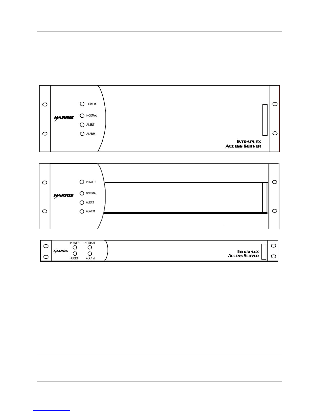
Full size, “3RU” shelves (ACS-163, ACS-165, ACS-166, STL-163, STL-165, and STL-166) are 5¼" high
(Figures 1-1 and 1-2). Compact, “1RU” shelves (ACS-167, ACS-168, and ACS-169) are 1¾" high
(Figure 1-3).
The 1RU versions perform the same functions as their 3RU counterpar ts but differ in the
● Number of channel modules they can accommodate
● Type of power supply used
● Physical orientation of th e modu les in the shelf
● Connection poin ts for alarm relays and a ring gener a tor
These differences are poin ted ou t in the appropriate sections throughout this manual.
Note: The ACS-166 and ACS-169 Dual Terminal Access Servers use different midpla nes from those
used in the ACS-163 Terminal Access Server, ACS-165 Drop and Insert Access Server, ACS168 Drop and Insert Access Server, STL-163 Studio-to-Transmitter Link , and STL-165 Studioto-Transmitter Link multiplexers. It is not possible to u s e th es e five multiplexers as dual
terminal access servers.
The ACS-163 and ACS-167 terminal multiplexers each terminate one T1 circuit. The ACS-165 and
ACS-168 multiplexers each terminate two T1 circuits and allow channels to pass between the two
circuits as well as to terminate at the multiplexer.
1-2 Harris Corporation
Intraplex Produc ts
Page 15
1 – Introduction ACS-160 Series & STL-160 Series T1 Multiplexer Installation & Operation
INTRAPLEX
STL HD
Version 2.11, August 2011
The ACS-166 and ACS-169 product packages each provide two T1 terminal multiplexers in a single
shelf. The multiplexers share the same power su pply a nd alarm reporting system but are otherwise
independent; ther e is no communication between th e two T1 circuits.
Note: Unless oth er wise specified, all references to the ACS-163 multiplexer also apply to the ACS-
167 multiplexer, all refe rences to the ACS-165 multiplexer also apply to the ACS-168
multiplexer, an d a ll references to the ACS-166 multiplexer also apply to the ACS-169
multiplexer.
Figure 1-1. ACS-163, ACS-165, and ACS-166 Multiplexers, Front View (with cover)
Figure 1-2. STL-163, ST L -165, and STL-166 Multiplexers, Front View (with cover)
Figure 1-3. ACS-167, ACS-168, and ACS-169 Multiplexers, Front View (with cover)
1.4 Multiplexer Component Parts
1.4.1 Main Equipment Shelf
The main equipment shelf is 19" wide rack-mount, 5¼" high for a 3RU multiplexer or 1¾" high for a
1RU multiplexer. This equipment shelf has slots for
● Plug-in common modules
● Channel modules
● Module adapters
● Power supplies
Warning! All common modules , channel modules, and power s upp lies must be inserted so that the
white eject tab is at the bottom in a 3RU shelf and at the right in a 1RU shelf.
Harris Corporation 1-3
Intraplex Products
Page 16

ACS-160 Series & STL-160 Series T1 Multiplexer Installation & Operation 1 – Introduction
Version 2.11, August 2011
1.4.2 CM-5RB Common Modules
There is one common module in a terminal multiplexer and two comm on modules in a dual terminal or
drop and insert multiplexer . Each CM-5RB common module provides one T1 port. Section 1.5 – CM5RB User Interface gives details on this c om m on module. For optional time delay capability, use the
CM-5R-TD module.
1.4.3 Channel Mo dules
There are one or more channel modules for
● Voice
● Data
● High fidelity audio
● Special applications
Each channel module may terminate one or more payload cir c uits (Section 2.1.6 – Channel Modules).
1.4.4 Module Adapters
All common and channel modules require module adapters, which inser t direc tly behind each module
and provide the circ uit connector(s). Every ch annel module works with at least one ty pe of module
adapter, and some channel modules are compatible w ith several module adapters, each one providing
a different type of connector or circuit interface.
Each CM-5RB common module is normally shipped with an MA-215 module adapter. The MA-215
adapter can support module redundancy through the addition of a CA-412 cable and a second CM-5RB
module. Systems preconfigured for module and line redundancy (for example, the ACS-163R-ACC
system) come equipped with two CM -5R B modules and (one each) MA-235-1 and MA-235-2 module
adapters. MA-215 and MA-235 module adapters provide RJ-48C T1 connections with CSU c apabilities.
Systems without line redundancy can be equipped with DB-15 T1 connectors by us ing MA-217B
module adapters.
1.4.5 Power Supplies
One power supply is always included, and a second one may be added in 3RU shelf systems for power
supply redundancy. ( A redu ndant power supply cannot be installed in a 1RU shelf.) Th e standard
power supply for the 1RU sh elf is a 30-watt, universal AC supply. There should be a minim um of 2RU
unoccupied space below th is s helf. For the 3RU shelf, the standard power supply is a 60-watt,
universal AC supply, with a minimum of 2RU unoc c upie d space below the shelf. There ar e a lso 50-watt
DC supplies for 3RU shelves, in -48VDC -24VDC versions, which require at least a 1RU of space
between shelves.
Intraplex also produ ces optional 95-watt supplies for use in 3RU shelves with high power
requirements. These a re a ls o universal AC supplies and also require a minimum of 2RU of un oc c upied
space below the shelf. (The type a nd number of channel modules in the multiplexer determine the
power requirements. Each channel module installation and operation manual gives power r e quirement
details. Section 7 – “Specifications” includes a listin g of Intraplex power supplies.) Figure 1-4 through
1-15 show the physical placement of the ACS-160 components in the equipment shelf.
1-4 Harris Corporation
Intraplex Produc ts
Page 17
1 – Introduction ACS-160 Series & STL-160 Series T1 Multiplexer Installation & Operation
Version 2.11, August 2011
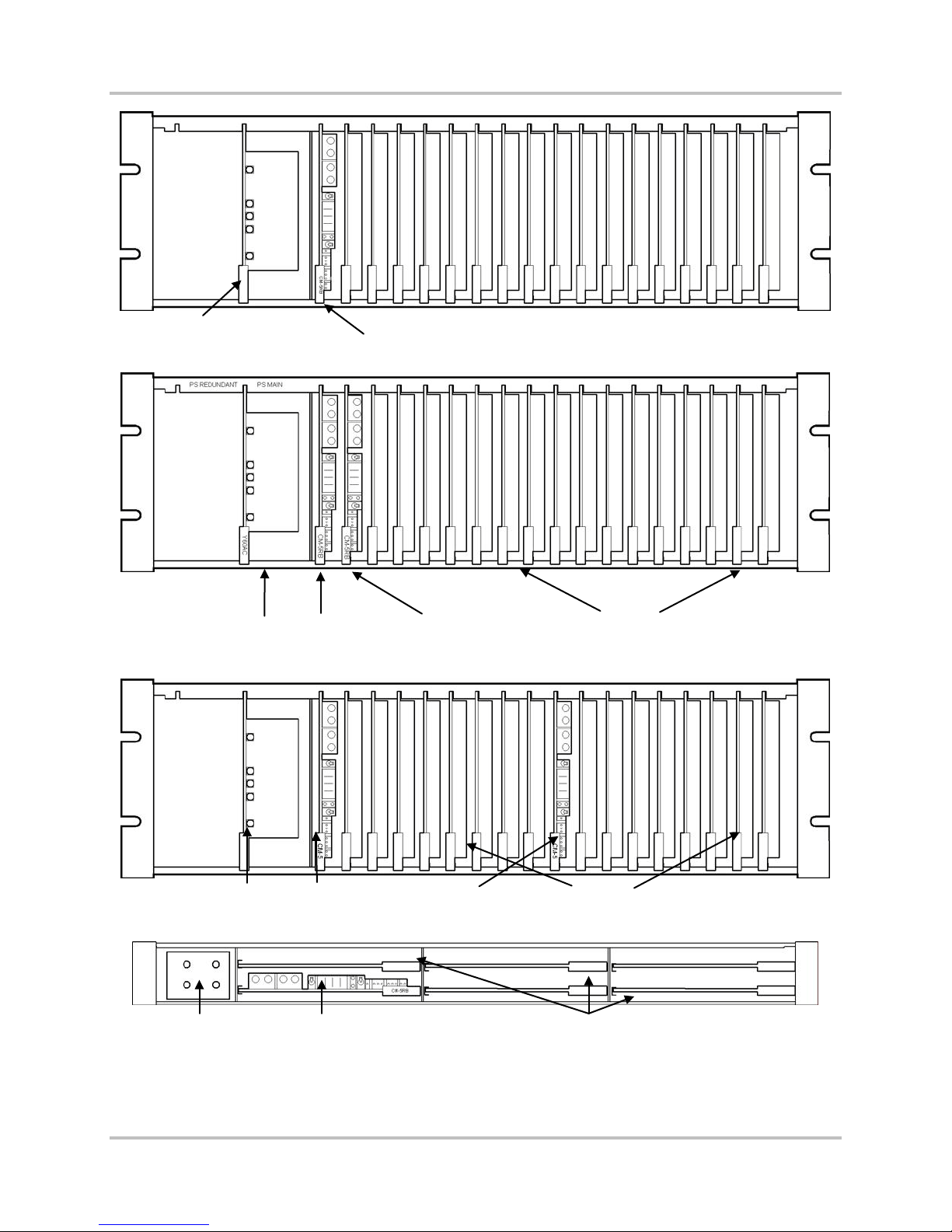
Primary Power Supply
CM-5RB
Figure 1-4. ACS-163 Multiplexer, Front View (no cover)
Primary Power Supply
Primary Power Supply
Power supply CM-57RB
DI-A
CM-5RB
DI-B
CM-5RB
16 slots for channel modules
Figure 1-5. ACS-165 Multiplexer, Front View (no cover)
First CM-5RB 16 slots for channel module s Second CM-5RB
Figure 1-6. ACS-166 Multiplexer, Front View (no cover)
5 slots for channel modules
Figure 1-7. ACS-167 Multiplexer, Front View (no cov er)
Harris Corporation 1-5
Intraplex Products
Page 18
ACS-160 Series & STL-160 Series T1 Multiplexer Installation & Operation 1 – Introduction
Version 2.11, August 2011
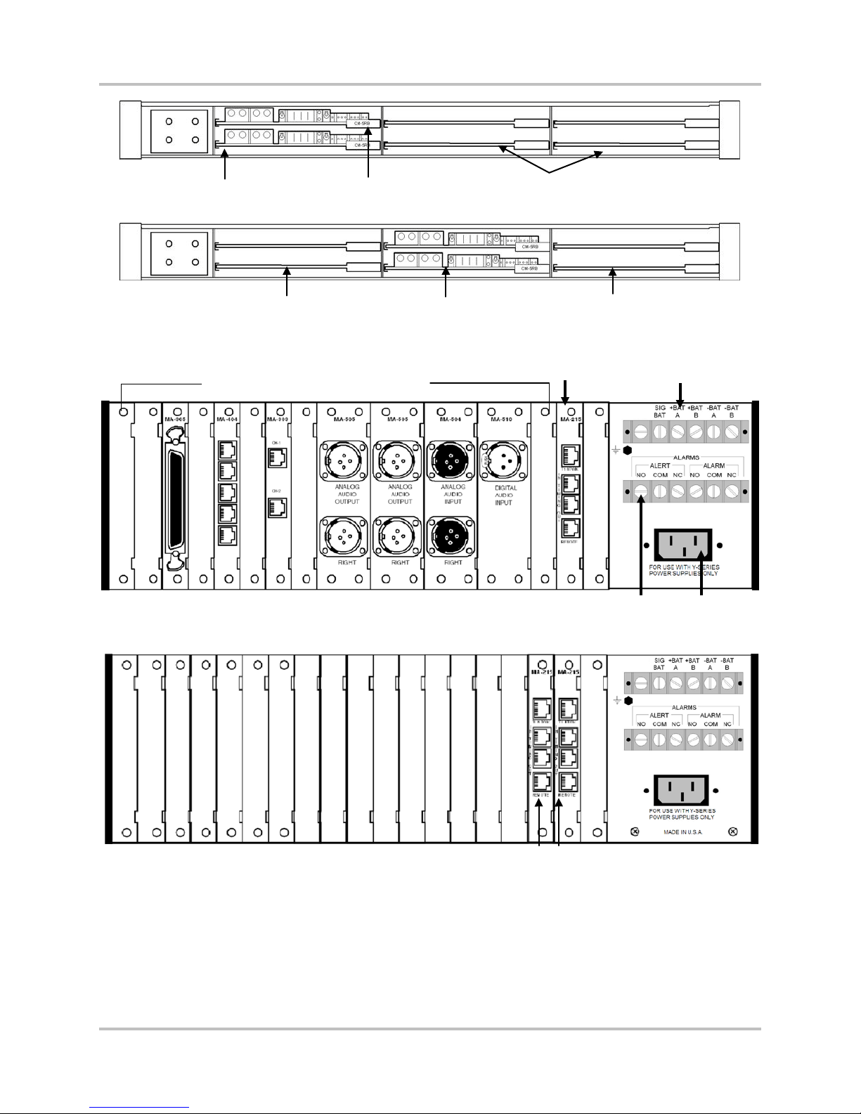
DI-B CM-5RB
DI-A CM-5RB
4 slots for channel modules
Figure 1-8. ACS-168 Multiplexer, Front View (No Cover)
Top CM-5RB controls these
channel modules
Two CM-5RBs
(ACS-169 only)
Bottom CM-5RB controls
these channel modules
Figure 1-9. ACS-169 Multiplexer, Front View (no cover)
Module adapters for common modules
MA-215 for
CM-5RB
Terminal strip 1
(DC power)
Terminal strip 2
(alert and alarm relays)
AC power in
Figure 1-10. Equipped ACS-163 Multiplexer, Rear View
Figure 1-11. ACS-165 Multiplexer, Rear View
1-6 Harris Corporation
Intraplex Produc ts
MA-215 for each CM-5RB
Page 19
1 – Introduction ACS-160 Series & STL-160 Series T1 Multiplexer Installation & Operation
Version 2.11, August 2011
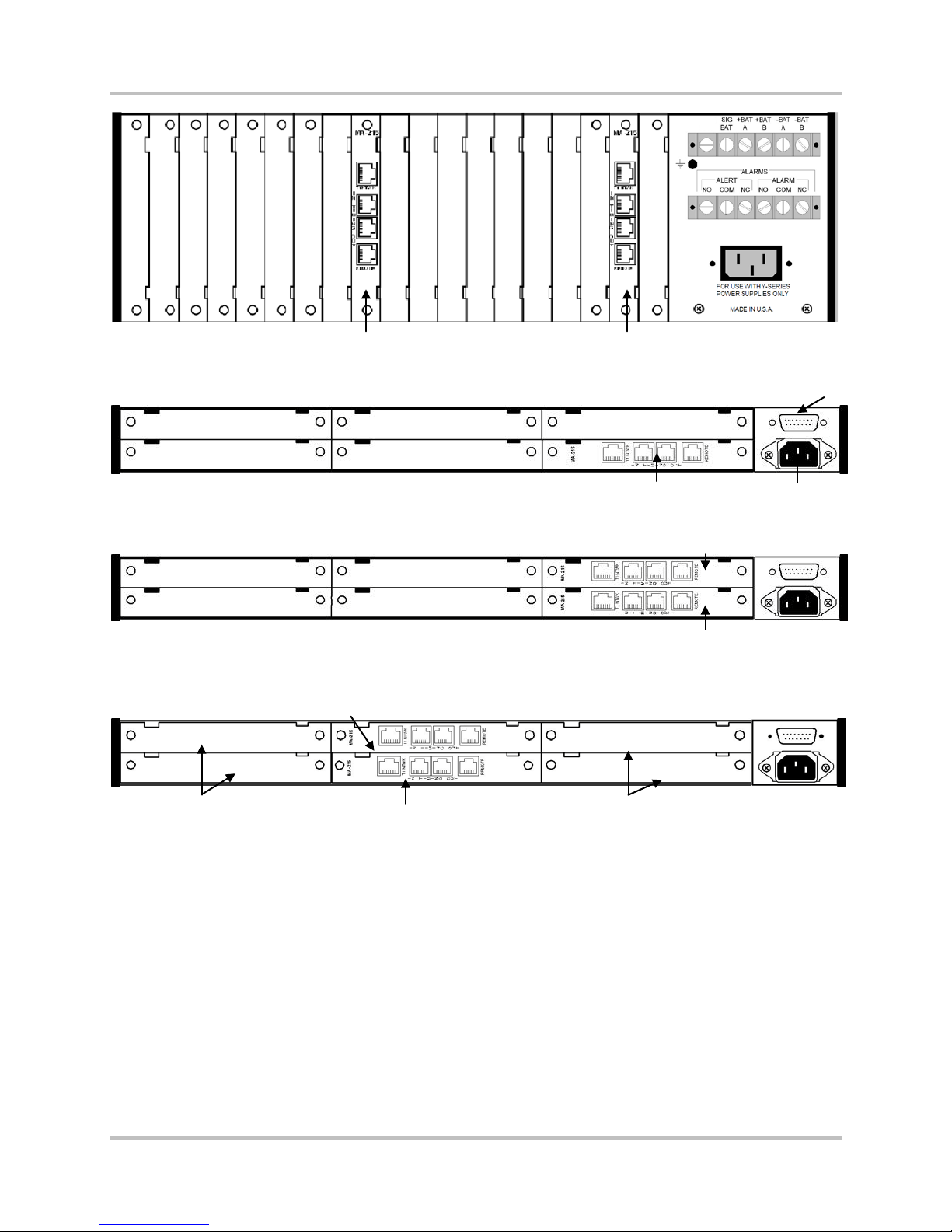
MA-215 for second CM-5RB MA-215 for first CM-5RB
Figure 1-12. ACS-166 Multiplexer, Rear View
Connector for alarm out, signal
battery, and ring generator input
Figure 1-13. ACS-167 Multiplexer, Rear View
MA-215 for DI-B CM-5RB
MA-215 for DI-B CM-5RB
Figure 1-14. ACS-168 Multiplexer, Rear View
Bottom CM-5RB controls
these channel modules
MA-215 for first CM-5RB
MA-215 for first CM-5RB
Top CM-5RB controls
these channel modules
Figure 1-15. ACS-169 Multiplexer, Rear View
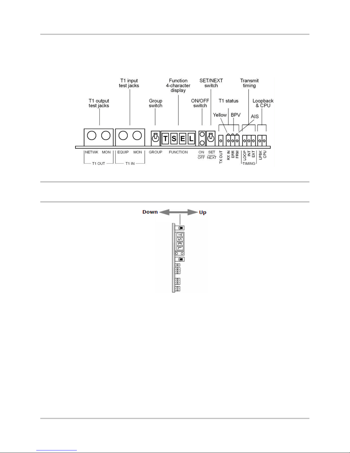
1.5 CM-5RB User Interface
This section describes the ACS-160 Series local user interface. Section 5 – “Remote Control O p er ation”
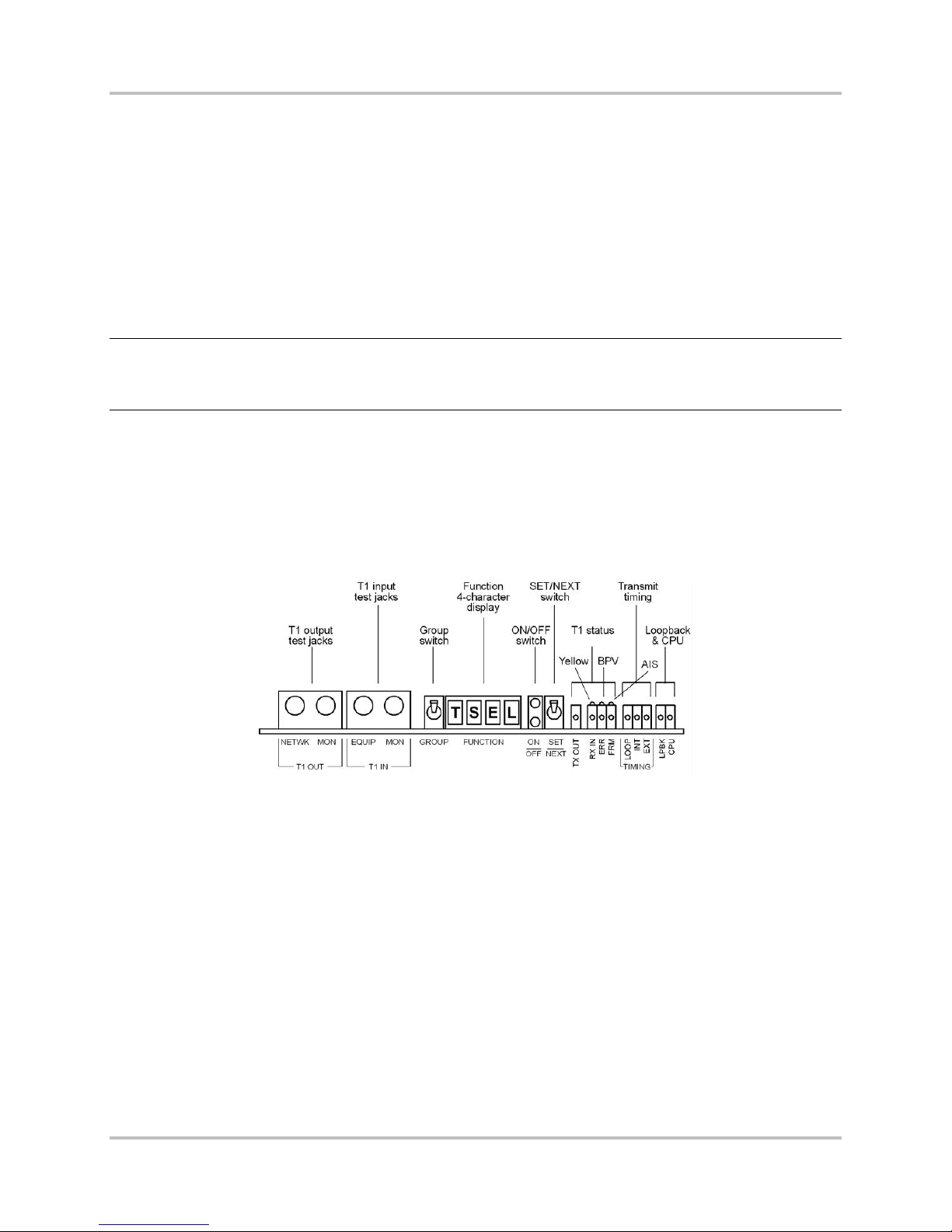
gives details on us ing the remote interface. The jacks, switches, and indicator lights on the CM-5RB
common module form the primary user interface f or the ACS-160 Series (Figure 1-16) multiplexers.
This user interface falls into three basic categories:
● Test Access: The left side of the module contains T1 input and output test jacks.
● Configuration: The center section contains these items that work together so that you can view
and change CM-5RB operational parameters:
• The GROUP and SET/NEXT switches
• A four-character alphanumeric display for abbreviated group and function names
• A bi-level indicator light set (gr een on top, red on bottom) that shows whether the function
displayed is currently active
Harris Corporation 1-7
Intraplex Products
Page 20
ACS-160 Series & STL-160 Series T1 Multiplexer Installation & Operation 1 – Introduction
Version 2.11, August 2011
● Status Monitoring: Twelve indicator lights appear on the right side for
• T1 status
• Primary timing status
• Loopback activity
• CPU activity
Figure 1-16. CM-5RB Module, Front View
Note: Because CM-5RB m odules install vertically in 3RU sh e lves, “UP” and “DOWN” on the toggle
switches actually refer to right and left respectively in an ACS-163, AC S-165, ACS-166, STL163, STL-165, or STL-166 multiplexer (Figure 1-17).
Figure 1-17. CM-5RB GRO U P a n d SE T /NEXT Switches in 3RU Shelf
1.5.1 Function Gr oups and Configuration Switches
The user-accessible CM-5RB functions are organized into groups and include
● Setup options such as SF and ESF (frame formats).
● Current status c onditions such as receiving all ones .
● Informational items such as the CM-5RB firmware revision.
The groups are accessed f rom two dif ferent configuration group menus.
● Basic configurat ion: This group menu provid es the settings used in most configuration setups.
Section 3.2 – CM-5RB Basic C onfiguration Group Menu gives a detailed explanation of the menu
settings.
● Advanced configuration: This group menu provides settings for CM-5R-TD functions and other
specialized applications that rarely need adjustment in most systems. Section 3.3 – CM-5RB
Advanced Configuration Group Menu gives a detailed explanation of the menu settings.
1-8 Harris Corporation
Intraplex Produc ts
Page 21

1 – Introduction ACS-160 Series & STL-160 Series T1 Multiplexer Installation & Operation
Version 2.11, August 2011
1.5.1.1 CM-5RB Function Displaying
When the CM-5RB display is blank or when a func tion is displayed, press down on the GROUP toggle
switch to view the name of the currently selected group. Once the current group name is display ed,
press down on the G ROUP switch again to select the next group or press up to select the previous
group, until the desired grou p is dis played.
Press down on the SET/NEXT switc h to display the first function in the currently selected group. Once
a function appears, press down on the SET/NEXT sw itc h repeatedly until the desired function is
displayed.
The bi-level indicator light set to the right of the function dis play indicates the status of the currently
displayed function. If the top (green) light is on, this function is active. If the bottom (red) light is on,
the function is not active.
1.5.1.2 CM-5RB Function Setting
To turn on a function that is not currently active, press up twice on the SET/NEXT switch while that
function is on the display. Pressing up once causes the top (green) light to blink, indicatin g that a
setup change takes place if the SET/NEXT switch is pressed up again. Actually pressing up on the
SET/NEXT switch a second time causes the green light to turn on continuously, indicating that the
selected setup parameter has been changed to the currently displayed setting. I f a function is already
active, pressing up on the SET/NEXT switch again causes no status or setup changes.
For example, if the display shows ESF while frame format is set to SF, the red light is on. Pressing up
on the SET/NEXT switch once causes the top (green) light to blink. Pressing up on the SET/NEXT
switch a second time actually changes the current T1 framing forma t from SF to ESF – the red light
goes out, and the green light stays on.
It is important to n ote that some setup functions are mu tually exclusive; activating one function
automatically deactivates another, such as
● Line code (you can set the line code to AMI or B8ZS but not both).
● Frame format (you can set the frame format to SF or ESF but not both).
Other functions are not mutually exclusive, such as the CM-5RB Line (LnLB) and Equipment (EqLB)
loopbacks in the LPBK group, which may both be activated at the same time.
1.5.2 Indicator Lights
In addition to the indicator lights on the CM-5RB common m od ule, four system status indicator lights
located on the power supply are visible when the front cover of the shelf is on (Figures 1-1 and 1-2).
Table 1-1 summarizes the meaning of the indicator lights on both the CM-5RB common module and
the power supply. For all the lights, “on” means the light is on continuously; “blink” means a rh ythmic,
one-half second on, one-half second off pulse; and “flash” means erratic flickering. Table 2-1 in
Section 2.1.3.7 gives more details for CM-5RB indicator lights, and Table 2-8 in Section 2.1.5 gives
more details for pow er supply indicator lights.
Harris Corporation 1-9
Intraplex Products
Page 22

ACS-160 Series & STL-160 Series T1 Multiplexer Installation & Operation 1 – Introduction
Version 2.11, August 2011
Table 1-1. CM-5RB and P ower Supply Status Indicator Lights
Indicator
Light Group Light Description
T1 Status
(CM-5RB)
T1 Error and
Alarm
(CM-5RB)
Timing
(CM-5RB)
System
Status
(CM-5RB)
System
Status
(Power
Supply)
TX OUT (Green) On when transmit output is detected.
RX IN (Green) On when receive input is detected. Blinks steadily when the receive input signal is
all ones, a yellow alarm, or has excess jitter. May flash if there is excess noise on
the input signal.
ERR (Yellow) On when logic errors are detected.
BPV On when bipolar violations are detected .
FRM (Red) On when T1 signal is out of frame or no signal is being received.
YEL (Yellow) On when there is a yellow alarm.
AIS On when an Alarm Indication Signal (AIS) has been detected.
LOOP (Green) On when loop timing is active (through timing on a drop/insert multiplexer).
INT (Green) On when internal timing is active.
EXT (Green) On when exter nal timi ng is active .
LPBK (Yellow) On when any inte rnal loopback is active.
CPU (Red) On when the CM-5RB central processing unit has failed.
POWER (Green) On when the multiplexe r is powe re d .
NORMAL (Green) On when no alert or alarm is present.
ALERT (Yellow) On when an alert condition exists.
ALARM (Red) On when an alarm condition exists. Section 6.3.5 defines alert and alarm
conditions.
1-10 Harris Corporation
Intraplex Produc ts
Page 23

No header here
Section 2 – Functional Design
This section expla ins the functions of the ACS-160 and STL-160 Series multiplexer components and
describes how to us e the multiplexers to configure both point-to-point and drop and insert T1
systems.
2.1 Component Func tionality
2.1.1 Main Equipment Shelf and Midplane
All modules, module adapter s , a nd power supplies plug into the main equipment shelf. These
components commu nicate with each other via the shelf midplane (or motherboard), which contains
both signal and power d is tribution buses (Figure 2-1).
Note: The ACS-166 and ACS-169 Dual Terminal Access Servers use different midpla nes from those
used in the ACS-163 Terminal Access Server, ACS-165 Drop and Insert Access Server, ACS168 Drop and Insert Access Server, STL-163 Studio-to-Transmitter Link , and STL-165 Studioto-Transmitter Link multiplexers. It is not possible to use these five multiplexers as dual
terminal access servers.
Power enters at eith e r the AC or battery connectors and passes to the power supply. The power supply
provides three voltages to th e power distribution bus (+5 VDC, +15 VDC, and -15 VDC), from which
each common and channel modu le dr a w s c urrent as needed. Power supplies from the signaling battery
and ring generator, if u sed, also connect to the power distribution bus.
Harris Corporation 2-1
Intraplex Products
Figure 2-1. Midplane Connections
Page 24
ACS-160 Series & STL-160 Series T1 Multiplexer Installation & Operation 2 – Functional Description
Version 2.11, August 2011
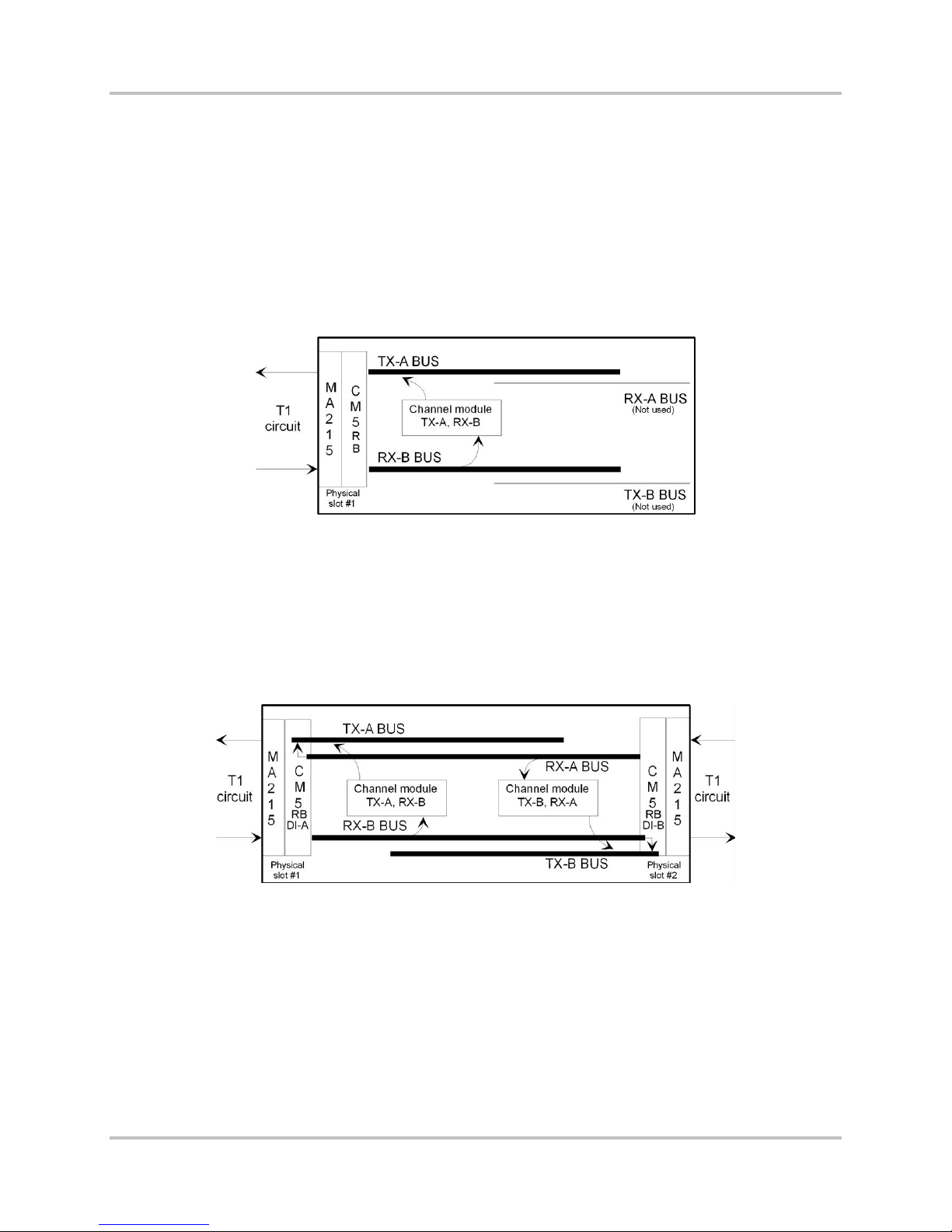
2.1.2 Drop and Insert Operation: the Signal Bus Role
The signal bus actually includes four buses:
● TX A bus
● RX A bus
● TX B bus
● RX B bus
In a terminal multiplexer, the channel modules pla c e their transmit signals on the TX A bus. The CM5RB common module ta kes these signals and multiplexes them together for transmiss ion on the T1
line. It also takes the incoming T1 signal, demultiplexes it, and places the resulting c hannel signals on
the RX-B bus, from which the channel modules take their individual rec eive data (Figure 2-2).
Figure 2-2. Terminal Multiplexer Signal Bu s
Each channel module has a bus selection switch that sets its transmit and receive directions. This
switch is generally labeled TX-A BUS or TERM. Setting the TX-A BUS or TERM switch on ensures that
the module transmits on the TX-A bus and receives from the RX-B bus, as required in a terminal
multiplexer.
In a drop and insert multiplexer, setting the TX-A BUS or TERM switch on sets a channel module to
transmit and rece ive via the CM-5RB module designated as DI-A. Settin g the TX-A BUS or TERM
switch off (up) sets a channel module to transmit and r eceive via the CM-5RB module designated as
DI-B, using the TX-B bus and the RX-A bus (Figure 2-3).
Figure 2-3. Drop and Insert Multiplexer Signal Bus
On some older channel module designs, there are two switches, one for the transmit side and one for
the receive side. These two switches should alway s be set to opposite dire c tions. In a terminal
multiplexer, or to communicate via the DI-A port in a drop and insert multiplexer, set the sw itches to
transmit A, rece ive B. To communicate via the DI-B port in a drop and insert multiplexer, set the
switches to trans m it B, receive A. Individual channel module manuals give the location and labe ling of
these switches on the modules provided with this sy stem.
As Figure 2-3 shows, in a drop and insert multiplexer, the RX-A bus connects to the TX-A bus, and the
RX-B bus connects to the TX-B bus. When there are no active channel modules in a dr op a nd insert
multiplexer, all T1 signal time slots coming from each direction transfer to the outgoing T1 signal in
the other directi on. When any transmit-only or full duplex channel modules are insta lled a nd active,
their output overrides th e data coming through on their selected time slot(s). Data in time s lots not in
2-2 Harris Corporation
Intraplex Produc ts
Page 25
2 – Functional Des c ription ACS-160 Series & STL-160 Series T 1 M ultiplexer Installation & Operation
Version 2.11, August 2011
use by any local channel module pass es th r ough as before. You can use a receive-only channel
module to monitor a channel passing through without affecting its passage.
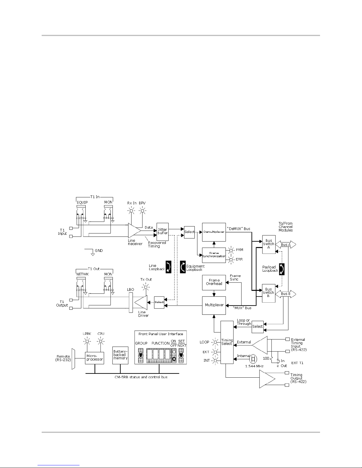
2.1.3 CM-5RB Common Modules
The CM-5RB common module, the c or e building blocks of ACS-160 and STL-160 Series multiple xers,
provides one full-duplex T 1 port. The ACS-163 or ACS-167 terminal multiplexer has one CM-5RB
module. The ACS-166 or ACS-169 dual terminal multiplexer, or the ACS-165 or ACS-168 drop and
insert multiplexe r , has two CM-5RB modules.
The CM-5RB module provides these basic operational fu nctions:
● Channel multiplexing to form the T1 aggregate
● T1 line driver (output)
● Transmit timing functions
● T1 line receiver (input)
● T1 aggregate demultiplexing to individual channels
● Loopback configurations
● Microprocessor control
● User interface
Figure 2-4 shows a fu nctional diagram of the CM-5RB module.
Figure 2-4. CM-5RB Common Module T1 Functional Diagram
Harris Corporation 2-3
Intraplex Products
Page 26

ACS-160 Series & STL-160 Series T1 Multiplexer Installation & Operation 2 – Functional Description
Version 2.11, August 2011
2.1.3.1 Channel Multiplexing to Form T1 Aggregate
The CM-5RB common module develops midplane bu s synchronization signals. The tr ansmit section of
each channel mod ule synchronizes to these signals a nd places its data onto the selected bu s. The CM5RB module then form s the aggr ega te signal, using either the ESF (extended superf ra m e) or S F ( D 4
superframe) framin g format. ESF is the preferred format and you should use it in all cases except
when the network or CSU cannot support it. Section 2.2.1.1 – T1 Frame Formats gives more details on
these two formats.
The CM-5RB module uses tri-state bus drivers and receivers to permit routin g the multiplexer and
demultiplexer bus signals t o eith er midplane bus (Bus A or Bus B). This versatile bus capability
enables simple multiplexer configuration for terminal or drop and in sert use (Section 2.1.2 - Drop and
Insert Operation : the Signal Bus Role).
2.1.3.2 T1 Line Driver
Line coding can be s et to either B8ZS (Bipolar with 8 Zero Substitution) or AMI (alternate mark
inversion). B8ZS is the preferred format; you should always use B8ZS, unless the network or channel
service unit cannot support it. Section 2.2.1.2 – T1 Line Coding gives a des c r iption of these line coding
methods.
Equipment and monitor test jacks on the front of the m odule accept input of miniature bantam plugs.
They allow the T 1 output of the multiplexer to be connec te d to a T1 transmission test set or to be fed
directly into the in p ut of another multiplexer during be nch testing.
The T1 line output connection is via the MA-215 module adapter. In s er tin g a plug into the T1
equipment out jack b r eaks the outgoing connection to the MA-215 module adapter. Terminating
impedance should be 100 ohms ba la nced. The T1 monitor out jack permits test access to the line
output without brea king the T1 line connection. Equ ip m ent connected to this jack shou ld also provide
a 100 ohm terminati on impedance. The signal level a t this point is approximately 20 decibels below
the line output level.
2.1.3.3 T1 Line Receiver
T1 input should be at the standard DS-1 digital cross connect level (DSX-1). T1 frame format can be
either ESF or SF. The line code can be either B8ZS (bipolar with 8-zero substitution) or AMI (a lte r nate
mark inversion). The lin e receiver
● Accepts the input signal.
● Recovers receive timing.
● Decodes the bipolar s ig nal.
A jitter buffer f ollows to smooth out the timing jitter usually present on an incoming signal.
The CM-5RB module receives T1 line input via the MA-215, MA-216, MA-217B, MA-235-1, or MA-235-
2 module adapter. Equipment and monitor T1 in jacks function like the T1 out jacks described
previously. All eq uipment connected to them should provide 100 ohms termination. T he equipment in
jack breaks th e c onnection to the T1 line input; the mon itor in jack does not, but the sign al level at
the monitor jack is about 20 decibels below the input level.
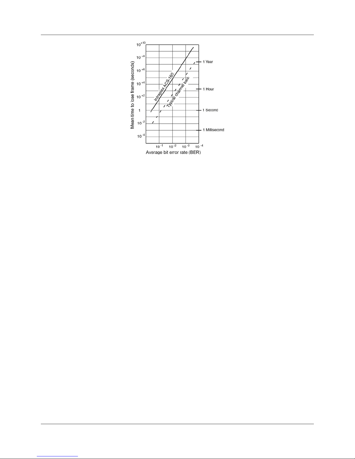
2.1.3.4 T1 Aggregate Demultiplexing to Individual Channels
The decoded line receive signal feeds the demultiplexer circuitry. First, the dem ultiplexing circuitry
achieves frame synchronization, using a proprietary robust framing algorithm that assures fast frame
acquisition and a high tolerance to errors once a frame is acquired. The average frame time for the SF
format is 4 milliseconds and for the ESF format is less than 18 milliseconds. Mean time to lose frame
in the presence of a high (10
-3
) random bit error rate exc eeds s everal hours (Figure 2-5).
2-4 Harris Corporation
Intraplex Produc ts
Page 27
2 – Functional Des c ription ACS-160 Series & STL-160 Series T 1 M ultiplexer Installation & Operation
Version 2.11, August 2011
Figure 2-5. Mean Ti me to Lose T1 Frame Synchronization
Once frame synchroniza tion is achieved, the demultiplexer develops the proper dem ultiplexing bus
signals and feeds them to all the channel modules plugged in to th e s helf. Bus signals include
● Demultiplexed chann el da ta .
● Demultiplexing sy nchronization status.
● Synchronization signals necessary for proper dec oding by the channel modules.
2.1.3.5 Loopback Configurations
The CM-5RB common module provides three loopback options (Figure 2-4):
● Line – Use the line loopback to test the transmission path integrity and th e T1 connections to the
multiplexer. This loopback takes the decoded T1 receive signal coming f r om the line receiver/jitter
buffer and loops it back to the T1 line driver input. Receive data also pas ses on to the
demultiplexer.
● Payload – Use the payload loopback to verify CM-5RB module operation up to the bus interface to
the channel module s . Data also passes on to the receive side of the channel modules.
● Equipment – Use the equipment loopback to test individual c hannel modules in the multiplexer.
It loops the transm it s ignals at the multiplexer output back to the demultiplexer in put. During
equipment loopba c k, the T1 output of the CM-5RB module is an all-ones signal.
Section 5.2.3.2 – Shelf-Level and Common Module Remote Ac c es s gives more information on
loopbacks.
2.1.3.6 Microprocessor Control and Battery-Backed Memory
The microprocessor chip used on all Intraplex common m od ules contains a lithium battery, which is an
inextricable element of th e m icr oproc es sor and is not independently replaceable. The lithium battery
powers the memory on the chip and thus retains setu p information whenever operating power is
removed, which might occur at any of these times:
● When equipment is stored or in transit
● When the module containing the chip is removed from a powered shelf
● When there is a tem p or a r y loss of power, other than unintentional or c atastrophic
In the design of Intraplex equipment, battery failure does not affe c t p r oper operation while the
equipment is under operati ng power. Battery failure does not become evident until power is removed
and the equipment is subsequ ently repowered. Upon repowering, the alphanumeric disp la y on the
common module flas hes “ERR 0” or remains blank.
Harris Corporation 2-5
Intraplex Products
Page 28
ACS-160 Series & STL-160 Series T1 Multiplexer Installation & Operation 2 – Functional Description
Version 2.11, August 2011
The lithium battery on the microprocessor chip has a data retention time of at least 10 years and an
expected shelf life of at least 20 y ea r s . In this context, “data retention time ” is the time when power is
removed (the battery is active) , and “shelf life” is the time when the shelf is powered ( th e ba ttery is
inactive).
Intraplex maintenance offers equipment repair by replacing inoperative plug-in modules. A failed
lithium battery c auses the common module on which the battery is mounted to fail. (Although, as
previously stated, this failure does not actually oc cur until operating power is rem oved and restored.)
To restore the mult iplexer to service, perform these steps:
1. Replace the failed module with a spare common module.
2. Return the failed unit to the factory for microprocessor replacement.
Warning! Intraplex common modu les may contain replaceable batteries. There is a danger of
explosion if a repla c ea ble battery is incorrectly replaced. Only replace this ba ttery with the
same or equivalent type recom mended by the manufacturer. Dispose of used batteries
according to the manufacturer’s instructions .
2.1.3.7 CM-5RB User Interface
To enable user settings and display status information, the front edge of the CM-5RB module (Figure
2-6) has
● Two switches.
● A four-character alphanumeric display.
● Several indicator l ig hts.
Figure 2-6. CM-5RB Common Module, Front View
Use GROUP and SET/NEXT Switches and Alphanumeric Display
The user-accessible CM-5RB module functions are organized into groups, which include
● Setup options such as SF and ESF (frame formats).
● Current statu s c onditions such as receiving all ones.
● Informationa l item s such as the CM-5RB firmware revision.
Detailed explan ations of the basic CM-5RB functions appear in these sections:
● T1 operational functions (TIME and TSEL) in Section 4 – “Setup and Configuration”
● Remote access setup functions (ADDR and SIO) in Section 5 – “Remote Control Operati on”
● Diagnostic functions (LPBK, BLNK, RVU1, and DIAG) in Section 6 – “Testing and
Troubleshooting”
Use the GROUP switch to select a particular function group and the SE T/NEXT switch to view and
set functions within the currently selected group. The four-character alphanumeric display shows
2-6 Harris Corporation
Intraplex Produc ts
Page 29

2 – Functional Des c ription ACS-160 Series & STL-160 Series T 1 M ultiplexer Installation & Operation
Version 2.11, August 2011
both group and function names, and the bi-level ON/OFF indicator lights sign ify the status of the
currently displayed function.
Display CM-5RB Functions
To display the CM-5 R B functions, perform these steps:
1. When the CM-5RB display is blank or w hen a function is displayed, press down on the group
toggle switch to view the name of the currently selec ted gr oup.
2. Once the current group name is displayed, press down on the group switch again to select the
next group or press up to select the previous group, until the desired group is displayed.
3. Press down on the SET/NEXT switch to display the first fun c tion in the currently selected
group.
4. Once a function appears, press down on the SE T/NEXT switch repeatedly until the desired
function is displa yed.
The bi-level light to the r ight of the function display indicates the status of the currently displayed
function. If the top (green) light is on, this function is active. If the bottom (red) light is on, the
function is not active.
Set CM-5RB Functions
To turn on a function that is not currently active, press up twice on the SET/NEXT switch while
that function is on the display. Pressing up once causes the top (green) light to blink, indicating
that a setup change takes place if the SET/NEXT switch is pressed up again. Actually pressing up
on the SET/NEXT switch a second time causes the top (gree n) light to turn on continuously,
indicating that the selected s etup parameter has been changed to the currently displayed s etting.
If a function is already active, pressing up on the SET/NEXT switch again causes no status or
setup changes.
For example, if th e d is p la y shows ESF while frame format is s e t to SF, the red light is on. Pressin g
up on the SET/NEXT switch once causes the top (green) light to blink. Pressing up on th e
SET/NEXT switch a second time actually changes the current T1 framing format from SF to ESF—
the red light turns off, and the green light is on continuously.
It is important to n ote that some setup functions are mu tually exclusive; setting on e function
automatically deactivates another. Examples include
● Line code (you can set line code to AMI or B8ZS but not both).
● Frame format (you can set frame format to SF or ESF but not both).
Other functions are not mutually exclusive. For ex ample, CM-5RB Line (LnLB) and Equipment
(EqLB) loopbacks in the LPBK group may be set at the same time.
Read CM-5RB Module Indicator Lights
Table 2-1 gives CM-5RB indicator lig ht descriptions. For all the lights, ON m eans the light is on
continuously; BLINK means a rhythmic, one-half second on, one-half second off pulse; and FLASH
means erratic flickering.
Harris Corporation 2-7
Intraplex Products
Page 30

ACS-160 Series & STL-160 Series T1 Multiplexer Installation & Operation 2 – Functional Description
Version 2.11, August 2011
Table 2-1. CM-5RB Indicator Lights
Light Description
TX OUT
(green
RX IN
(green)
ERR
(yellow)
YEL
(yellow)
BPV
(yellow)
AIS
(yellow)
FRM
(red)
LOOP
(green)
INT
(green)
EXT
(green)
LPBK
(yellow)
Transmit output
ON The transmissio n signa l is normal. I t can be a data signal or, if idle, an all-ones signal.
OFF No signal is being transmitted, indicating a hardware failure.
Receive input
ON A data signal is detected at the C M-5RB T1 rece ive r inp ut.
OFF No signal is dete c ted at the receiv er inp ut.
BLINK One of these signals or conditions is d e tecte d (se e n on the BLNK group disp lay):
Rx11 - A framed or unframed all-ones signal, produced by an idle condition at the far end (an
unframed all ones is a T1 alarm indication signal (AIS ))
RxYL - A yellow alar m , ind ic a ting a loss of the rece ive s ignal at the far end (if the equipment
at the far end is set up to generate a yellow alarm)
XsJt - Excess jitter, indicating the jitte r buffer depth has been exceeded. This light might
flash if there is noise on the line.
Errors
FLASH Light flashes each time a CRC-6 error is detected.
Yellow alarm
ON An “upstream” failur e . Loss of signa l dete c ted fro m an upstream source.
Bipolar violations
FLASH A light flashes each time a bipolar violation is detected.
ON The random bit error ratio excee d s 10-5.
Alarm Indication Signal
ON An upstream failure has been detected.
Out of frame
ON CM-5RB T1 receiver is not in frame synchronization, which might b e caus ed by a high bit
error ratio, the absence of a T1 receive signal, or improper CM-5RB module configuration.
Loop or through timing
On ACS-163 terminal multiple x e r
ON The T1 transmitter is loop timed.
BLINK The loop is selected for primary timing, but the module is currently using fallb a c k timing .
On ACS-165 drop and insert multiplexer
ON The T1 transmitter is through timed.
BLINK Through is selected for primary timing, but the module is currently using fallback timing .
Internal timing
ON The CM-5RB transmitter is using its internal 1.544 MHz clock.
External timing
ON The CM-5RB transmitter is using timing provided by an external cl o ck .
BLINK External is selected for primary timing, but the module is currently using fallbac k timing .
Loopback
ON One or more of three internal CM-5RB loopbacks (line, equip m e nt, or pay load ) is active.
2-8 Harris Corporation
Intraplex Produc ts
Page 31

2 – Functional Des c ription ACS-160 Series & STL-160 Series T 1 M ultiplexer Installation & Operation
Version 2.11, August 2011
Table 2-1. CM-5RB Indicator Lights (cont inued)
Light Description
CPU
(red)
Central processing unit of CM-5RB module
ON A microprocessor or memory fault has been detected on CM-5RB module. CPU failure is
reported as an alarm to shelf alarm circuitry. T his light turns on briefly at power-up.
2.1.4 Redundancy
ACS-160 Series multiplexers can have two levels of redundancy:
● Module redundancy – Two CM-5RB modules are installed and, if the primar y one fails, the backup
module takes over.
● Module and line redundancy – Not only are two CM-5RB modules insta lled , but two T1 lines are
also connected. The system is protected against either the primar y CM-5RB module or the primary
T1 circuit failing .
2.1.4.1 Redundant CM-5RB Module Operation
The CM-5RB module installed in front of the MA-235-1 module adapter assumes the role of “Primary
CM.” The CM-5RB module installed in front of the MA-235-2 assumes the role of “Backup CM.” During
normal operation, both primary and backup common m odules transmit the same T1 payload data
through both the primary and backup lines. Only one common module, the “Active CM,” is used at a
given time to receive T1 data. The common module not being used to process received T1 data is
called the “Standby CM. ”
● Primary: The CM-5RB module installed in fr ont of the MA-235-1 module adapter.
● Backup: The CM-5RB module installed in front of the M A-235-2 module adapter.
● Active: The CM-5RB module passing received T1 data.
● Standby: The CM-5RB module not passing received T1 data.
Based on the switching of a particular system, either the primary or backup CM -5RB module can be
the Active common module. At initial system start-up, the primary CM-5RB module is automatically
set as the Active CM.
The primary CM configured for terminal or DI -A mode automatically turns on in the Primary role. W hile
in this role, the primary CM constantly searches for backup CM-5RB modules on the shelf and, if it
finds one, periodically reports status to backup through the multiplexer bus, including
● Mode.
● Hardware status.
● Line status.
Note: Th e p r oc e s s of transmitting shelf data fr om a Primary to a Backup CM-5RB module can be
slow. With a full shelf of 18 modules, it can take up to two f ull minutes for the Primary CM5RB module to transmit an entire shelf image to the backup CM-5RB module.
The backup CM-5RB module monitors the report from the pr imary CM. If the report fails to arrive, or if
the report indicates a hardware failure or a line fa ilure, the backup CM compares the repor t to the
switching criteria set in the REDN group (Section 4.6 – Redundancy Configuration Group (REDN)). If
the failure and switch criteria match, the backup CM module takes control of the MA-215 module
adapter. A signal generate d f r om th e m odule adapter takes the failed primary CM off the multiplexer
bus.
In a drop and insert multiplexer, the primary CM-5RB module in the DI-A mode holds the channel
module configuration information; the DI-B CM-5RB module does not hold this information. The DI-A
CM-5RB module queries the DI-B CM-5RB status and reports it to the DI-B backup CM-5RB module
(Figure 2-7). The DI-B backup CM-5RB module then takes appropriate action. Since DI-B CM-5RB
Harris Corporation 2-9
Intraplex Products
Page 32

ACS-160 Series & STL-160 Series T1 Multiplexer Installation & Operation 2 – Functional Description
Version 2.11, August 2011
modules do not hold c hannel module configuration information, the switchover fr om a backup DI-B
CM-5RB module to a primary one is fixed at two seconds.
Figure 2-7. Redundan t CM-5RB Function s in Drop and Insert Multiplexer
2.1.4.2 Switch from Ba ckup to Primary CM-5RB Module
In revert (RVRT) configuration, the backup CM -5RB module autom atically reverts control back to the
primary CM-5RB module when it detects that a hardware failure ha s been c orr ec ted. If you have
selected a line failure (LOF, LOS, YEL, AIS) for a switching criterion, the configura tion should be set to
non-revertant (NVRT ) du e to the s witching mechanics. For exa m ple , if a yellow alarm is received and
a switch occurs, the primary CM-5RB module no longer reports a yellow a larm because the signals are
no longer coming into it. If the switching is set to revert ( RVRT), the failure appears repair ed to the
backup CM, and the backup switches control back to the primary CM. The primary CM once again
detects an alarm and another backup switch occurs. This cycling of the switch back and forth between
redundant CM s continues until the alarm condition is r em oved.
The non-revertant configuration should also be set if the switches for loss of frame (LOF) or loss of
signal (LOS) are activated (ON), also due to switching mechanics. The module adapter directs the T1
line signals to only one CM-5RB. If the backup CM-5RB module is active, it h as the T1 line signal. The
primary CM-5RB module can never regain the line signal and therefore r em a in s in a failed condition.
A switch is initiate d 50 m s after a report is received tha t m ee ts the switching criteria. The tota l time for
switching from the primary CM to a backup CM (or vice versa) is less than 100 ms but results in a loss
of frame and signal during that period of time.
When reverting ba ck to the primary, the backup CM must first transmit the channel module
configuration s ettings to the primary CM-5RB . W hile the backup CM is transmitting the configuration
settings, the front pan el displa y reads “WAIT.” The transmission of the configuration settings can ta ke
up to two minutes f or a full shelf of 18 channel modules. When setting transmission is com p lete, the
“WAIT” display clears and the switchover is initiated (switchover appears to be instantaneous).
2.1.4.3 Module and Line Redundancy
Module and line redundan cy features are available with these common modules:
● CM-5RB module for T1 systems
● CM-5RTD module for Time Delayed T1 systems
Notes: The CM-5R common module, an earlier version of the CM-5RB module, is the first genera tion
CM to combine line and module redundancy. The CM-5RB module should not be used in the
same equipment shelf as the CM-5R module.
Any combination of the CM-5RB module in a single equipment shelf with older version
common modules does not fun c tion properly (that is, a CM-5RB module cannot act as a
backup for a CM-5R or vice versa). To determine if a common module has combined module
and line redundancy capa bili ty, check the ejector tab. It has one of these labels: “CM-5RB,”
“CM-5R,” or “CM-5RTD.”
2-10 Harris Corporation
Intraplex Produc ts
Page 33

2 – Functional Des c ription ACS-160 Series & STL-160 Series T 1 M ultiplexer Installation & Operation
Version 2.11, August 2011
Table 2-2 lists the common modules which the CM-5RB can replace.
Table 2-2. Interoper a bility Chart
Application CM-5RB Replaceable?
CM-5, TERM Yes
CM-5, DI Yes, replace both DI-A and DI-B
CM-5, TERM, Module Redundant Yes, replace both primary and backup
CM-5, DI, Module Redundant Yes, replace all 4 CMs
CM-5R Yes, replace both
In order to use combined module an d line redundancy, these components must be installed in a
chassis in adjacent module slots:
● Two common modules (a pair of CM-5RB modules)
● One MA-235-1 module adapter with RJ-48C conn ec tor
● One MA-235-2 module adapter with RJ-48C conn ec tor
● One CA-202 shielded cable that connects the two module adapters
Note: The MA-235-1 and MA-235-2 module adapters are the only adapters qualified to use with both
line and module redundanc y . MA-215 or MA-217A/B adapters can be used with the CM-5RB
module for module-only redundancy. You should install the MA-235-1 and MA-235-2 adapter s ,
as they have the capability to u pgr a de to l ine redundancy at a later date.
Figure 2-8 shows a component-level diagram of the system.
Figure 2-8. Combined Module and Line R edundancy Block D iagram
The MA-235-1 module adapter provides the T1 interface for the primary line and the port is labeled
“T1/E1 Primary.” The MA-235-2 module adapter provides the T1 connec tion for the backup line
through the port labeled “T1/E1 Backup.” Both module adapters work as a pair but are implemented
as two separate adapters. This arrangement is designed to allow replacement of a failed MA without
interruption to th e active service.
Harris Corporation 2-11
Intraplex Products
Page 34

ACS-160 Series & STL-160 Series T1 Multiplexer Installation & Operation 2 – Functional Description
Version 2.11, August 2011
2.1.4.4 Module Failure Detection and Switching
If module redundancy is enabled, detecting a failed primary modu le initiates a switch to the backu p
module within 500 milliseconds of the failure condition. Module switching does not occur if
● Backup module is in a failed state.
● Backup module has been removed f r om the shelf.
● Module redundancy has been turned off.
If both modules have failed, s er v ic e is in ter rupted. If one module has failed, a shelf alert is generated
if a successful switchover to the remaining good module has occurred. If a successful switchover has
not occurred (most likely du e to module redundancy being turned off), a shelf alarm is generated.
As a general rule, a protec tion switch from the primary to the backup common module (CM) does not
cause a switch to th e ba ckup T1 line. The primary T1 line, connected to the MA-235-1 module
adapter, is redirected through the CA-202 cable and the MA-235-2 module adapter t o th e backup CM5RB module (Figure 2-9), ensuring th at traffic remains on the primary T1 line independent of the
module-switching activity.
Figure 2-9. Signal Flow after Prima ry Module Failure
An exception to this ge neral rule can occur if the prima r y and backup T1 facilities require different
interface settings for framing type, transmit line build-out, or T1 line code, as in dicated by your
selecting the MLINE setting or by using the Front Panel User Interface (FPUI). In these rare situation s,
the interface settings on the primary CM only works with the primary T1 line, and the settings on the
backup CM only work with the backup T1 line. To maintain proper interface operation in these cases, a
primary CM failure results in a switch of both the module and the line.
A module switch c a n be manually forced using either the front-panel switches on the F r ont Panel User
Interface or by issuing ISiCL commands. If the user manually forces a module switch, the system
switches back according to the normal protocols for re version. For a permanent manual switch, set
module redundan c y mode to OFF before the manual switc h is initiated.
2.1.4.5 Module Redundancy Revertive Operation
You can configure module redu ndancy for revertive or non-revertive switching. This feature can be set
separately for line and module redundancy. If enabled, module redundancy r evers ion oc c urs as soon
as a working primary module replaces a failed primary module and the backup module’s channel
2-12 Harris Corporation
Intraplex Produc ts
Page 35

2 – Functional Des c ription ACS-160 Series & STL-160 Series T 1 M ultiplexer Installation & Operation
Version 2.11, August 2011
module configura tion data has been downloaded to th e pr im ary module. The configuration data
downloads automatically when a working module is in stalled.
The replacement primary comm on m odule should be pre-configured before installation. Before
reversion occur s, channel module configuration da ta is automatically downloaded from the backup CM5RB module to the repla c ement primary CM-5RB module. During this download proc ess, the word
“WAIT” is displa yed on the front panel of the backup CM . Reversion to the primary CM can be
manually forc e d e ither from the front panel switch es or via ISiCL even if automatic rever s ion is
disabled.
2.1.4.6 Line Failure Detection and Switching
A switch from the pr imary T1 line to the backup T1 line is initia ted by the equipment upon detect ion of
line failure conditions. Table 2-3 shows the available line failure con d itions and their types. You can
either enable or disable ea c h condition.
Table 2-3. Line Failure Conditions
Line Failure Conditions Failure Type
Loss of Frame (OOF or LOF) Hard Failure
Loss of Signal (LOS) Hard Failure
Alarm Indication Signal (AIS ) Hard Failure
Excessive Bit Error Rate (BER) for T1 ESF (Extended Superframe).
Programmable thresholds are 10
Excessive Bit Error Rate (BER) for T1 SF (Superframe). T hresho ld is : 10-3* Soft Failure
Unavailable Signal State (UAS)* Soft Failure
Remote Alarm Indication Signal (RAI S or Yello w ) Soft Failure
-3
, 10-4, 10-5, or 10-6*
Soft Failure
* When operating in AEC mode (Section 2.1.4.11 – Module or Line Redundancy Alarms and Alerts),
Unavailable Signal State ( U A S) is declared after 10 consecutive Severely Errored Sec on ds ( SES) and
cleared after 10 error-free seconds, where an SES is defined as a second with 101 or more errors. For
Standard (non-FTI) mode, UAS is declared after 10 c onsecutive SES and cleared after 10 consecutive
non-SES, where an SES is a second with 320 or more errors.
Intraplex equipment monit ors the performance of both the primary and backup T1 lines a nd assigns a
type code to it:
● Good
● Soft Fail
● Hard Fail
Good condition is pr e ferable to Soft Fail condition. Accordingly, Soft Fail is better than Hard Fail. When
a switch in line oc c urs, both the backup CM-5RB module and MA-235 module adapter become active
(Figure 2-10).
Harris Corporation 2-13
Intraplex Products
Page 36

ACS-160 Series & STL-160 Series T1 Multiplexer Installation & Operation 2 – Functional Description
Version 2.11, August 2011
Figure 2-10. Signal F low after Primary Line Fail ure
Table 2-4 shows the detection times for the selectable T1 line BER thresholds. Detection times are
different for E1 lines.
Table 2-4. BER Threshold Detection Times
Detection Time (Seconds) 10-3 10-4 10-5 10-6
Extended Superframe (ESF) 10s 10s 30s 105s
Superfr ame (SF) 30s N/A N/A N/A
The CM-5RB module monitors both the pr im ary and the backup lines for th e s e sof t a nd hard failure
conditions. If line redun da ncy is enabled, the module compares the primary line is compared with the
backup line and decides w hich line to use. If the primary is Good, no switch is made. If the primary is
either Soft Fail or Hard Fail and the backup is Good, a switch is made. If the primary is Hard Fail and
the backup is Soft Fail, a switch is made. Tables 2-5 and 2-6 summarize these revertive/non-revertive
switching priori tie s .
Table 2-5. Failure S witching Precedence : Rev/Non-Rev Line Re dunda ncy and Primary Line
Backup Line Status
Good Soft Hard
Good P P P
Soft B NC P
Primary
Hard B B NC
Line
Status
P = Primary Line is a ctive
B = Backup Line is active
NC = No Change (current state)
2-14 Harris Corporation
Intraplex Produc ts
Page 37

2 – Functional Des c ription ACS-160 Series & STL-160 Series T 1 M ultiplexer Installation & Operation
Version 2.11, August 2011
Table 2-6. Failure S witching Precedence : Non-Revertive Line Redundancy and Backup Line
Backup Line Status
Good Soft Hard
Good B P P
Soft B NC P
Primary
Hard B B NC
Line
Status
P = Primary Line is a ctive
B = Backup Line is active
NC = No Change (current state)
Detection times f or line failures depend on the nature of the failure conditions. The tota l time to switch
to line protection after the start of any Hard Failu r e con dition does not exceed 500 milliseconds,
including detection time and re-frame time, unless a switching delay time has been selected (the SDLY
group in the LRDN menu on Table 4-23).
You can select from a range of a vailable line switching delays. The selected delay begins when a line
failure condition is detected. If the condition pers ists throughout the delay period, the line is switched.
The programmable switchi ng delay values are
● 0 seconds.
● 0.5 seconds.
● 1 seconds.
● 10 seconds.
You can manua lly force line switch ing via the front panel switches or ISiCL command. If a line switch
is forced manua lly, the system reverts according to normal failure switching precedence. For a
permanent manual switch, set line redundancy m od e to O FF before initiating the manu al switch.
2.1.4.7 Manual Switching for Line Failure
If a line failure condition occurs and is later cleared but the c ontrol is not reverted to the primary CM5RB common module (CM), you can manually switch by
● Removing and reinstalling the primary CM.
● Manually switching at the front panel display (MRDN >> PRIM).
2.1.4.8 Line Redundancy Revertive Operation
You can configu r e line redundancy for revertive or non-revertive switching separate ly for line and
module redundan c y. If you select revertive switchin g for line redundancy, operation retu r ns to the
primary line after a user-program m a b le delay at the conclusion of th e pr im ary line failure. You can
program this delay to
● 10 seconds
● 1 minute
● 5 minutes
Reversion to the prim a r y line only occurs if the primary is in “Good” condition or in better condi tion
than the backup.
If you select non -revertive switching, operation retu rns to the primary line if manually forced via the
front panel switc hes, by using ISiCL commands, or if the p r im a ry line becomes “better” than the
backup line (Tables 2-5 and 2-6). Figure 2-10 shows T1 signal flow after a line switch ope r a tion to the
backup line. In this state, both transmit and receive T1 traffic flows through the backu p CM.
Harris Corporation 2-15
Intraplex Products
Page 38

ACS-160 Series & STL-160 Series T1 Multiplexer Installation & Operation 2 – Functional Description
Version 2.11, August 2011
2.1.4.9 CM-5RTD Time Delay Common Modules
You can remotely control the delay feature on the r edundant CM-5R-TD common module. However,
there are a few a dditional requirements for configuration of redundant time delay common modules.
The time delay fu nction (TDLY) in the basic menu group a nd the time delay parameter (Topt) in the
advanced menu group must be configured identically on all CM-5R-TD configurations. Also, the SCB
address (1-36) of each CM-5R-TD must be unique. Section 4.7 – Integrated Time Delay has add itional
details on the time delay option.
2.1.4.10 Line Failure Far-end Operation
Independent switching decisions are made at each end of the line-redundant s y stem. Consequently, a
unidirectional failure within a T1 facility could r esult in a switch occurring at only one end of the
circuit. In this case, traffic would be split with ou tbound traffic traveling on one T1 ser vice and the
return traffic traveling on the other – a potentially cumbersome line maintenanc e s ituation. You can
prevent this situation by selecting Yellow Alarm a s a line s witching criterion. After the c or rect
integration time , the end of the circuit that detects the line failure sends Yellow Alarm . The Yellow
Alarm, in turn, causes the other end of the circuit to switch, ensuring that both directions of T1 traffic
are on the backup T1 line. Yellow Alarm is always sent if LOS, LOF, or AIS a r e detected. Yellow is also
sent if UAS or BER have been selecte d a s s witching criteria and the selected error rate threshold h a s
been exceeded. Switching of ea c h end of the line is completed in 500 milliseconds with LSDLY ( lin e
switch delay) se t to 0. The 500 millisecond switching periods for the two ends of the lin e a re not timesynchronized.
2.1.4.11 Module or Line Redundancy Alarms and Al erts
Line or module failu r es that result in loss of service generate a shelf Alarm (Table 2-7). A failure of the
standby module or line that does not interrupt service generates a shelf alert. A failure of the active
module or line that results in a successful protection switch action generates a shelf alert and service
continues on th e b a c kup module or line.
Table 2-7. Alert/Alarm Line Condition Dependencie s
Line Condition
Condition Affects Active Line Condition Affects Standby
Loss of frame (OOF or LOF) Alarm Alert
Loss of signal (LOS) Alarm Alert
Alarm indication signal Alarm Alert
BER exceeds threshold Alarm* Alert*
Unavailable signal state (UAS) Alarm** Alert**
Remote Alarm Indication (RAIS or Yellow) Alert Alert
Loopback Alert Alert
* This condition applies only if selected as a switch ing criterion. Otherwise, it does n ot r e s ult in an
alert or alarm.
** This condition applies only in AEC mode or if selected as a switching criterion in non-AEC modes.
Otherwise, it does n ot result in an alert or alarm.
No alarm or alert cond itions are generated due to the condition of the backup T1 line if line
redundancy m od e is set to “NOBK” (no backup). This setting is typically used for systems installed
without a backup T1 line.
The FTI mode is an a d ditional Event condition mode. When operating in FTI mode, three addition a l
Event conditions a r e in effect for line redundancy.
Alarm/Alert Indicatio n
2-16 Harris Corporation
Intraplex Produc ts
Page 39

2 – Functional Des c ription ACS-160 Series & STL-160 Series T 1 M ultiplexer Installation & Operation
Version 2.11, August 2011
● The “2-15 Event” is declared if 2 or more errored sec onds are detected in the most recent 15
minutes of operation and is c lea r ed if there are fewer than 2 errored seconds in the most recent
15 minutes of operation. This Event is asserted for a minimum of 15 minutes.
● The “5-15 Event” is declared if 5 or more errored sec onds are detected in the most recent 15
minutes of operation and is c lea r ed if there are fewer than 5 errored seconds in the most recent
15 minutes of operation. This Event is asserted for a m inimum of 15 minutes.
● The “86-24 Event” is declared if 86 or more errored secon ds a re detected in the most recent 24
hours of operation and is clear ed if there are fewer than 86 errored seconds in the most recent 24
hours of operation . This Event is asserted for a minim um of 15 minutes.
In FTI mode, UAS is an alert if it does not interrupt ser vice (that is, if the UAS condition is on the nonactive line) and is an alarm if it interrupts service (that is, if the UAS condition is on the a ctive line). In
non-FTI modes, UAS is an alert or alarm condition under these sam e c ir cumstances, but only if it is
selected as a line s witching criterion.
In FTI mode and in UAS, the CM-5RB module
● Sends a T1 yellow alarm.
● Asserts an out-of-frame condition to all channel modules, which has the effect of muting audio on
most program audio and voice channel modules and asserting control signals on datacom to an
idle or off state).
● Changes the re c eive data sent to channel modules to all ones.
Like UAS, the Bit Error Rate (BER) is a n alert/alarm only if it has been selected as a line-switching
criterion in FT I or non-FTI modes. If selected as line-switching criteria, BER a nd UAS result in an alarm
or alert even if redundancy is disa bled; that is, LRDN CNFG = OFF or NOBK (line redundancy
configuration equals off or no backup).
2.1.4.12 T1 Transmitter Timing
In a terminal multiplexer, the CM-5RB common module enables selecting a primary timing source:
● Loop
● Internal
● External
In a drop and insert multiplexer, primary timing is always set to through. In the event of network or
link problems causing a loss of primary timing, an automatic, carefully controlled changeover to
fallback timing h elp s e liminate frame slips and mainta in circuit availability. The fallback timing source
is factory-preset to internal.
The T1 transmitter timing c a n be set up differently on the primary and backup module. However,
during operation both the primary and the backup module op e r a te from the same timing source,
which is the source specified for the curr e ntly active module. On the inactiv e or standby common
module, the T1 transmit timing is automatically sw itched to the same T1 transmit timing a s the active
common. The in dicator lights for timing are not aff ected. For example, if you switch th e inactive CM to
loop timing, all in dicator lights (Front Panel User Interface and ISiCL) are not affected and indicate
loop timing. How e ver, the inactive CM the operates on the s ame timing as the active CM. Section
4.4.1 gives details on setti ng primary and fallback timing.
2.1.4.13 T1 Loopbacks
T1 Line Loopback can be used on either the active or backup line at any time. Equipment Loopback
can only be activ ated on the active module. If Equipment Loopback is active at the time the module is
switched inactive, it is automatically turned off and hidden from view on the front panel display
(Section 6.3.1 – T1 Loopback Use).
Harris Corporation 2-17
Intraplex Products
Page 40

ACS-160 Series & STL-160 Series T1 Multiplexer Installation & Operation 2 – Functional Description
Version 2.11, August 2011
2.1.5 Power Supply Modules
The standard 1RU ACS-160 S eries pow er s upply is a 30-watt, universal AC supply, while the standard
3RU ACS-160 Series or STL-160 Series power supply is a 60-watt, universal AC supply. DC power
supplies for 3RU shelves are also available with inp ut voltages of 48 VDC and 24 VDC. An optional 95
watt universal AC supply is available for the 3RU shelf for applications with high power requirements.
Section 7 – “Specif ications” gives details on all available power supplies. Follow the Section 3.3 –
Multiplexer Ins ta llation guidelines about she lf spacing to avoid heat problems.
Note: The ACS-160 Series and STL-160 Series m ultiplexers allow for the combined use of AC and DC
power supply operation at the sa m e time.
A second power supply may be inserted in the sec on d power supply slot for power supply redundancy.
If the main supply fails, the s ec ond supply ensures uninterrupted operation. The redu ndant power
supply is optiona l a nd is not available for 1RU shelves.
Note: An a ddition a l pow er s upply is for redundancy only. For example, a 60-w a tt shelf with two
power supplies should only use 60 watts of power to assure that, if one power supply fails , the
configuration does not overload the existing power s upply.
Power supply modules require no special setup. As long as they are plugged into their slots a nd
system power is applied, th ey are operating.
Figure 2-11 shows the key system status indicator lights and the Alert and Alarm relays on the power
supply module. Th e s e status indicator lights and relay s respond to fault conditions detected in the
● Multiplexer.
● T1 circuit.
● Channel modules installed in the s helf.
Figure 2-11. Y-Series Power Supply Indicator Lights
Table 2-8 lists the indic a tor light meanings.
These four ind ic a tor lights are visible when the front cov e r of the multiplexer is closed:
● POWER
● NORMAL
● ALERT
● ALARM
The SUPPLY FAIL indicator light(s) are not visible when the cover is closed.
2-18 Harris Corporation
Intraplex Produc ts
Page 41

2 – Functional Des c ription ACS-160 Series & STL-160 Series T 1 M ultiplexer Installation & Operation
Version 2.11, August 2011
Table 2-8. Power Supply Indicator Li ghts (When On)
Light Description
POWER
(green)
NORMAL
(green)
ALERT
(yellow)
ALARM
(red)
SUPPLY
FAIL
(red)
The multiplexer has power. Remains on if one of two installed power s upp lie s has faile d and the
remaining supply has sufficient capac i ty to pow er the multip le x e r.
No alert or alarm condition exists.
When the ACO switch is on, indicates there is an alert at one or more channel modules . These CM-5RB
lights can assist in determining the alert co nd ition:
RX IN is not on - loss of receive signal
RX IN is blinking - receiving a yellow alarm
LPBK is on - internal loopback active
LOOP, INT, EXT is blinking - the fallback timing is activ ated, and the pri mary timing mode that is used
will be blinking
SUPPLY FAIL is on - (only when two power supplies are installed) I ndica te s a power supply failure.
When the ACO switch is on, there is an alert at one or more channel modules.
When the ACO switch is on, indicates there is an alert at one or more channel modules . This lig ht turns
on briefly at power-up. These CM-5RB lights can ass is t in deter mi ning the aler t condition:
CPU is on - The central processor unit failed.
RX IN and FRM are on - The signal is present but is out of frame.
TX OUT is on - There is no transmit output.
Power supply failure (the shelf is running on the supply whose SUPPLY FAIL light is not on).
As Table 2-8 indicates, when a shelf is equipped w ith two power supplies, the failure of one supply
creates an ALERT condition. The power supply also con ta ins the ACO (Alarm Cut-Off) switch. The ACO
switch disables the Alert and Alarm relays and is used to silence a local alarm. If two power supplies
are installed (only possible in a 3RU shelf), both ACO switches must be turned on to silence an alarm.
Turning on the A CO switch is one of the conditions that cause the Alert light to turn on. It has no
effect on the Ala r m light.
Power supply test points (E9, E10, E11, and E12) allow testing for proper voltages. Section 6.6.4 –
Power Supply Test gives the procedur e f or using these test points. Figure 2-12 contains a simplified
functional diagr am of the power supply.
Harris Corporation 2-19
Intraplex Products
Page 42

ACS-160 Series & STL-160 Series T1 Multiplexer Installation & Operation 2 – Functional Description
Version 2.11, August 2011
Figure 2-12. Power Supply Module Functional Diagram
2.1.6 Channel M odules
Intraplex produces a wide v a r iety of channel modules for the ACS-160 Series mu ltipl exers, including
these types:
● Voice Modules: Voice modules provide digital transport of telephony, fax and modem c ir cuits.
Signaling options include E&M Types I, II, III, V, loop start/ground start, ARD, and transmission.
These modules provide
• 2-wire Foreign Exchange Office (FXO/FXS) PCM and ADPCM voice.
• 4-wire E&M PCM and ADPCM voice.
• Wideband 7.5 kHz voice.
• Motorola SECURENET
● Data Modules: Data modules prov ide d igital transport of one-way or full-duplex data circuits,
supporting a variety of data rates and formats including synchronous, asynchronous, and
plesiochronous. These modules include
• High-speed synchronous data u p to 1.984 Mbps for 10Base LAN, V.35, X.21, RS-449, and TTL.
• 10BaseT Ethernet LAN bridging.
• Four-port asynchronous data up to 38. 4 kbps for RS-232 and RS-449.
• Five-port synchronous data u p to 19. 2 kbps for RS-232.
• High-speed synchronous data that can be optionally decou pled from the network timing at any
data rate up to 1.984 Mbps.
● Program Audio Mod ules: Program audio modules provide digital transport for signals up to 20
kHz stereo. They are available with analog or AES/EB U input or output. These modules inclu de
• Linear, uncompressed 15 or 20 kHz stereo au d io with minimum delay.
• Enhanced Apt-X 4:1 compressed audio for signals up to 20 Khz s ter eo w ith low dela y.
• ITU-T J.41 audio that employs 14:1 1 instantaneous companding.
• Full-duplex codec modules that provide MPEG Layer 2 and Layer 3 (MP3) compressed audio.
Each channel module’s transmit side converts its input into one or mor e 64 kbps time slots and places
this information onto the transmit bus on the midplane for multiplexing by the CM-5RB module
(Section 2.1.3 - CM-5RB Common Modules). Similarly, each ch an nel module’s receive side takes the
TM
secure digital voice.
2-20 Harris Corporation
Intraplex Produc ts
Page 43

2 – Functional Des c ription ACS-160 Series & STL-160 Series T 1 M ultiplexer Installation & Operation
Version 2.11, August 2011
incoming demultip lexed digital information fr om its designated time slot(s) on the receive bus on the
midplane and converts it back to its original format for output.
2.1.6.1 Simplex versus Duplex Channel Modules
Most circuit types, such as voice and two-way data circuits, are full-duplex;* that is, they sup por t
simultaneous tw o-way operation. Full-duplex circ uits require identical full-duplex (transmit/receive)
channel modules at both ends of the channel they occupy within an ACS-160 system. Other circuit
types, such as program audio channels, are simplex; that is, they always have a transmitter module
at one end and a receiver module at the other. Figure 2-13 shows multiple channel modules of various
types in a three-site system, using both terminal and drop and insert multiplexers.
* Most full-duplex (two-way ) ch annel modules can also be set up to operate in a simplex (one-way)
mode.
Figure 2-13. Channel Module Direct ion and Time Slot Settings
2.1.6.2 Channel Modules in Point-to-Point versus Point-to-Multipo int Ci rc u its
Most ACS-160 system circuits are point-to-point. However, you c an configure several channel module
types for point-to-mult ipoint operation. For example, you can set up a single program audio
transmitter module and sev er a l progra m audio receiver modules in a point-to-m ultipoint or broadcast
circuit configu r a tion, allowing multiple locations to receive the same program audio signal without the
need for tandem decoding an d r e-encoding at each receive site. To achieve the point-to-multipoint
configuration, set all the receive modules to the same time slots as the transmit module. Similarly,
data polling channel modules c a n be used to configure point-to-multipoint data circ uits. In this
arrangement, all the polling modules are set to use the same time slot, but each responds only when
it receives the Request-To-Send (RTS) signal.
Harris Corporation 2-21
Intraplex Products
Page 44

ACS-160 Series & STL-160 Series T1 Multiplexer Installation & Operation 2 – Functional Description
Version 2.11, August 2011
2.1.6.3 Relationship between Circuits and Time Slots
The T1 circuit con sists of twenty-four 64 kbps time slots in each direction (Section 2.2.1 – T1 Digital
Transmission). Some channel module types use a single time slot to provide one or more circuits. For
example, a single-port data m odu le m a y use one time slot to transmit one data c ir cuit operating at 64
kbps, while a five-port data module may use one time s lot to transmit up to five data circuits, each
operating at 9.6 kbps.
Other channel module types require multiple time slots per circuit. For example, wideband data
modules may be configured to op era te a t ra tes up to 1.536 Mbps and therefore may use from one to
twenty-four time slots, simplex or full duplex, within a given T1 circuit. Similarly, high fidelity a udio
channel modules may use up to eighteen time slots to support one 15 kHz, CD-qua lity stereo circuit.
Remember, however, tha t on e-way channels (high fidelity audio modules and data modules operating
in simplex mode) use time slots in one direction of the T1 circu it only; the same time slots remain
available for oth e r one-way channels in the return direction.
2.1.7 Module Adapters
All common and channel modules use plug-in module adapters to provide the connectors for the
individual and aggregate channel interfaces. In most cases, one module adapter is r equired for each
module on a one-to-on e ba s is ; however, certain module adapters provide connec tion s for more than
one module. Power supply modu les r equire no module adapters.
All module adapters have the same connector on their front edge to mate with the shelf midplane, but
some module adapters have differ ent rear edge connectors, providing a variety of interfaces (Figure 2-
14).
Figure 2-14. Module a nd Module Adapter I nsertion in 3RU (Side) or 1RU Chassis (Top)
For some chann e l m odules, one specific module adapter must be used to provid e th e c or rec t
connector(s). Other channel modules are compatible with several different module adapters, each
providing a differe nt interface. Each individua l channel module manual describe s the module
adapter(s) available for that module.
Warning! Hot insertion or re m oval of a module adapter while a channel module is in place is not
recommended, as it could damage the channel m odule or the module adapter. To
remove a module adapter wh ile the s ystem is turned on (has power), first remove the
associated cha nnel module. Similarly, to install a new channel module, first insta ll the
module adapter and then install the module itself.
2-22 Harris Corporation
Intraplex Produc ts
Page 45

2 – Functional Des c ription ACS-160 Series & STL-160 Series T 1 M ultiplexer Installation & Operation
1
2 3 23 24
24
23
3 2
1
64
kbps
64
kbps
64
kbps
64
kbps
64
kbps
64
kbps
64
kbps
64
kbps
64
kbps
64
kbps
Overhead
8 kbps
Overhead
8 kbps
Version 2.11, August 2011
2.2 System Functionality
2.2.1 T1 Digital Transmission
A single T1 circu it pr ovides twenty-four full-duplex, 64 kbps time slots to carry payload data, for an
aggregate payload capacity of 1.536 Mbps in each direction (24 x 64 = 1536). An 8 kbps overh ea d
channel brings the actual T 1 interface rate to 1.544 Mbps (Section 2.2.1.1).
Intraplex ACS-160 Series multiplexers provide an interfac e betw een T1 circuits and one or more
payload channels, which originate and terminate at plug-in channel modules. Channel modules
convert voice, pr ogr am audio, and data signals into a single or multiple 64 kbps digital sign als. These
64 kbps signals are then combined by time division multiplexing into a 1.544 Mbps T1 signal.
The T1 circuit is inherently duplex; that is, there ar e twenty-four time slots in each direction of the
circuit (Figure 2-15). Thus, while a two-way voice or data channel may occupy Time Slot 6 in both
directions, a on e -way audio signal using Time Slots 7 and 8 in one direction would allow those two
time slots to still be av a ilable to carry a different one-wa y signal in the other direction.
Figure 2-15. Train Re presentation of T1 Circuit Duplex Nature
2.2.1.1 T1 Frame Formats
The T1 signal contains 8,000 frames per second. Each frame consists of one 8-bit byte from each of
the 24 time slots, plus one overhead bit, used to provide frame synchronization, error dete c tion, and
other functions. Frames are arranged into larger groupings in on e of these two formats:
● Superframe (SF), which groups 12 frames together (Figure 2-16)
● Extended superframe ( ESF), which groups 24 frames together (Figure 2-17)
Whether a particular T1 line oper a tes with SF or ESF framing depends on the T1 service prov ider . The
ESF format provides better error detection than SF, and you should use it whenever possible;
however, some older netw orks and channel service units (CSUs) do not s upport the ESF format. ACS160 Series multiplexers ca n be set to operate using either SF or ESF fr a m e format.
Harris Corporation 2-23
Intraplex Products
Page 46

ACS-160 Series & STL-160 Series T1 Multiplexer Installation & Operation 2 – Functional Description
Version 2.11, August 2011
Figure 2-16. Superframe (SF) Format
Figure 2-17. Extended Superframe (ESF) Format
2.2.1.2 T1 Line Coding
To assist in detect ing transmission errors, all T1 lines use one of these two forms of line coding:
● AMI (alternate mark inversion)
● B8ZS (Bipolar With 8-Zero Substitution)
2-24 Harris Corporation
Intraplex Produc ts
Page 47

2 – Functional Des c ription ACS-160 Series & STL-160 Series T 1 M ultiplexer Installation & Operation
Version 2.11, August 2011
AMI is a simple bipolar coding scheme. Each “1” bit in the data strea m is given an opposite polarity
from the one before it, while each “0” bit is neutral (Figure 2-18). If two 1s in a row have the same
polarity, it is a b ipolar violation and indicates a tra nsmission error; the BPV indica tor on the CM-5RB
module flashes (flickers erratically) whenever a bipolar violation is detected.
AMI is an older system with a significant limitation: when the payload being transmitted c ontains too
many 0s in a row (a condition called “insufficient ones density”), the T1 circuit may lose frame
synchronization.
Figure 2-18. AMI Li ne Coding
To help prevent ins ufficient ones density on AMI networks, many Intraplex channel modules offer
methods of preven ting long strings of 0s from occurring. Th es e m ethods include
● Placing the payloa d da ta into alternate time slots (any unused time slots a r e a utomatically filled
with all ones).
● Using only 56 kbps instead of 64 kbps per time slot and filling every eighth bit with a 1.
● Incorporating a da ta scrambler that applies its own form of zero substitution to the data for that
channel.
B8ZS is a newer an d m or e r obust form of bipolar line coding that eliminates the problem of insuff icien t
ones density. With B8ZS, any time a string of eight con s e c utive zeroes appears in the payload
(Figures 2-19 and 2-20), it is replaced by a zero substitution code (a special sequence of ones and
zeroes) before transmissi on. At the receive end, this sequence is converted back to eigh t z er oes to
maintain data integ rity. Intentional bipolar violations are applied to signal the p r e s ence of a zero
substitution code ; whenever a bipolar violation is det ected on a B8ZS circuit, the multiplexer checks
the surrounding bit sequence to determine whether it is part of a zero substitution code or a true
transmission err or .
Figure 2-19. Original Payload with Eight Consecutive Zeroes
Harris Corporation 2-25
Intraplex Products
Page 48

ACS-160 Series & STL-160 Series T1 Multiplexer Installation & Operation 2 – Functional Description
Version 2.11, August 2011
Figure 2-20. B8ZS Zero Substitution Line Coding
B8ZS is the preferred form of line coding and should be used instead of AMI whenever possible.
However, some older networks do not support it.
2.2.2 Terminal Multiplexers
For terminal mult ip lexers, a 3RU shelf can accomm odate one or two plug-in power supplies, AC or DC .
A 1RU shelf contains a single, fixed AC power supply. The next sections discuss single and dual
terminal multipl e xers.
2.2.2.1 Single Terminals (ACS-163, ACS-167)
The ACS-163 and ACS-167 terminal multiplexers serve as an interface between a single T1 circuit and
multiple voice, program, data, and other types of p a yload circuits (Figure 2-21).
Figure 2-21. Single Terminal Multiplexer Configuration
The ACS-163 multiplexer is a 3RU (5¼" high) shelf that accommodates up to sixteen channel
modules, while th e ACS-167 multiplexer is a 1RU (1¾" high) shelf that accommodates up to five
channel modules. The 3RU shelf can accommodate one or two plug-in power supplies, AC or DC. The
1RU version contains a single, fixed AC power supply. The functionality of these two multiplexers is
otherwise identic a l.
2.2.2.2 Dual Terminal Multiplexer (ACS-166, ACS-169)
The ACS-166 dual terminal multiplexer is a 3RU (5¼" h igh) shelf that provides two separate T1
terminals in one chassis (Figure 2-22). Each T1 circuit is supported by one CM-5RB module and has
eight slots availa ble for channel modules. The ACS-169 is a 1RU (1¾" high) shelf that accommodates
up to four channel modules. The functionality of these two multiplexers is otherwise identical.
2-26 Harris Corporation
Intraplex Produc ts
Page 49

2 – Functional Des c ription ACS-160 Series & STL-160 Series T 1 M ultiplexer Installation & Operation
Version 2.11, August 2011
Figure 2-22. Dual Terminal Multiplexer Configuration
The two terminals are completely independent of eac h other in terms of data channels; there is no
drop and insert functionality, and no time slots pass between the two. However, they share the same
power supply and alarm system; an alert or alarm condition on either of the two terminals causes the
shelf to display ALERT or ALARM.
2.2.3 Point-to-Point Systems
The simplest type of ACS-160 system configuration is a point-to-point system, two terminal
multiplexers connected by a s ingle T1 circuit (Figure 2-23). The same payload circuits appear at both
ends of a point-to-point system.
Most payload types, such as voice and full-duplex data circuits, have both a n input and an output at
each terminal mu ltiplexer. However, some payload types, like simplex da ta a nd one-way program
audio channels, have an input at one multiplexer an d an output at the other, with no return signal.
Harris Corporation 2-27
Intraplex Products
Figure 2-23. Point-to-Point System
Page 50

ACS-160 Series & STL-160 Series T1 Multiplexer Installation & Operation 2 – Functional Description
Version 2.11, August 2011
The T1 circuit itse lf is always full duplex (Section 2. 2.1 - T1 Digital Transmission). With Intraplex
multiplexers, a ny time slots used by a one-way channel are s till available to carry an independent
one-way channel in the other direction. For example, if prog r a m audio is being transmitted on time
slots 1 to 4 from Location 1 to Location 2, you can transmit another audio prog r a m simultaneously on
time slots 1 to 4 from Location 2 to Location 1.
2.2.4 Drop and Insert Mu ltiplexers (ACS-165 and ACS-168)
An ACS-165 drop and insert multiplexe r is e s s e ntially a pair of back-to-back ACS-163 terminal
multiplexers in which some circuits terminate while others pass through (Figure 2-24). A dr op a nd
insert multiplexer can termina te payload circuits from either of tw o different T1 circuits (that is, f r om
either of two differ ent locations).
Figure 2-24. Drop and Insert Multiplexer Configuration
The ACS-165 multiplexer is a 3RU (5¼" high) shelf that accommodates up to sixteen channel
modules, while th e ACS-168 multiplexer is a 1RU (1¾" high) shelf that accommodates up to four
channel modules. The 3RU s helf can accommodate one or two plug-in power supplies, AC or DC. The
1RU shelf contains a single, fixed AC power supply . The functionality of these two mu ltip lexers is
otherwise identic a l. Section 2.1.2 – Drop and Insert Operation: the Signal Bus Role gives more details
on the internal w or kings of a drop and insert multiplexer.
2.2.5 Drop and Insert Syste ms
The addition of one or more drop and insert multiplexers c onverts a simple point-to-point syste m into
a drop and insert system (Figure 2-25). Data, voice, program a udio, and distribution (multiple-drop)
circuits can be es tablished between any two locations in a T1 drop and insert system.
2-28 Harris Corporation
Intraplex Produc ts
Page 51

2 – Functional Des c ription ACS-160 Series & STL-160 Series T 1 M ultiplexer Installation & Operation
Version 2.11, August 2011
Figure 2-25. ACS-165 Drop and Insert System
A three-location system can prov id e circuits between these location s
● 1 and 2
● 2 and 3
● 1 and 3
The only limiting f a ctor is the 24-time slot capacity of the T1 circuit between any two adjacent
locations. Drop and insert systems are not limited to a single drop and insert multiplexer. In fact, you
can use them to link as many a s on e hundred locations.
Harris Corporation 2-29
Intraplex Products
Page 52

No header
This page is left blank intentionally.
2-30 Harris Corporation
Intraplex Produc ts
Page 53

No header
Section 3 – Installation & Wiring
This section describes installation procedures and guidelines for ACS-160 Series installation, including
1. Unpack and inspect the ACS-160 Series equipment.
2. Install the multiplexer s helves.
3. Wire the power and signal connectors.
4. Apply power.
3.1 Tools & Cables Required
In addition to the I ntraplex equipment provided, th ese items are necessary to complete ins tallation:
● Basic telecommunications installation tool kit ( s crewdrivers, wire stripper, and so f orth)
● Rack mounting hardware (four threaded bolts per shelf)
● One four-wire shielded cable with RJ-48C connectors ( on e m a le end, one female end) for each T1
port
● T1 connecting cables
Normally, T1 connecting ca bles m a y run up to 150 feet in length. If your installation requires a
longer cable, please contact Intraplex Customer Service for a recommendation.
● Cables for each payload channel
RS-232, RS-449, and/or V.35 for da ta c hannels between the multiplexer and DTE equipment, 22 24 gauge wire for program audio channels, and RJ-11 or 50-pin telco for voice
Note: All pa yload channels connect to the multi ple xer via module adapters that plu g in at the rear of
the shelf. The in dividual channel module manuals p r ovide detailed descriptions of th e module
adapter(s) and cable requi rem ents for the modules shipped with the system.
● For DC-powered shelf, 16 - 18 gauge wire for power connection (an AC power cable is included if
the shelf is AC powered)
● Optional: one un shielded cable for each remote port, if you wish to use the remote access and
control feature (Section 2.6.4). For each module adapter, the multiplexer end of the cable requires
an RJ-11 connector.
● Optional: timing ca ble, if external timing input or output is required (Section 3.6.3)
● Optional: volt-ohm meter (VOM)
3.2 T1 Multiplexer Equipment Inspection
Upon receiving the equipmen t , complete these tasks:
1. Inspect all shipping cartons for damage.
2. If damage is observed, notify the shipper a s s oon a s possible.
3. Unpack all equipment from containers.
4. Inspect equipment for damage.
5. Verify that the multiplexers are equipped as expected, confirming items from the packing list (Bill
of Materials).
If you have any questions regardin g pos sible equipment damage or shipping errors, please contact
Harris Customer Service:
Harris Corporation 3-1
Intraplex Products
Page 54

ACS-160 Series & STL-160 Series T1 Multiplexer Installation & Operation 3 – Installation & Wiring
Version 2.11, August 2011
● U.S., Canada, and Latin America: +1-217-222-8200 or tsupport@harris.com
● Europe, Middle East, and Af r ica : +44-118-964-8100 or
● Asia and Pacific Rim: +852-2776-0628 or
Warning! Follow all of your company’s rules regarding AC or DC powered equipment installation. If
there is a conflict b etween any procedure in this manual and your company’s safety rules,
your company’s safety rules must take priority.
Service.europe@harris.com
BCDService@harris.com
3.3 Multiplexer Shelf Installation
ACS-160 Series multiplexers are normally shipped pre-configured, with common and channel modules
already installed. All modules and module adapters can remain in place while bolting each shelf into its
equipment rack.
1. Bolt the shelf into its equipment rack. Allow at least a 1RU (that is 1.75" high) of space between
shelves when using DC supplies or 2R U of s pa c e ( a total of 3. 5") when using AC supplies to avoid
possible heat problems.
2. Make sure all modules, module adapters, an d m odule interface units are seated properly.
Note: If the shelf is AC-powered, make sure that the power cable is accessible for maintenance
purposes.
Each 3RU Intraplex shelf can contain a second power supply for redundancy. If the main supply fails,
the system uses the redundant supply to continu e operating. Simply insert the second power supply
into the redundant supply slot on the front (indicator light turns on exactly as those on the main
supply). Due to space limitations, 1RU shelves do not h a ve the capacity for redundant power s upplies.
Power supply modules require no special setup. As long as they are plugged into their respective slots
and system power is applied, they operate normally. If a 3RU shelf is equipped with two power
supplies (main and redun da nt) and one of the supplies fails, it may be removed and a new supply
inserted without turning off the system.
3.4 Redundant CM-5RB Modules
3.4.1 Redundant CM -5RB Installation
The CM-5RB redundancy feature can be used with the MA-235-1 and MA-235-2 module adapters. A
multiplexer equipped with redundant CM-5RB modules automatically switches from the primary
module over to the backup module wh en it detects a line or hardware failur e. When the line or
hardware failure is repair ed, the backup CM-5RB module can revert (automatically or manually) to the
primary CM-5RB module.
Install the prima r y CM-5RB module in the same slot number as th e MA-235-1 module adapter. Install
the backup CM-5RB module in the slot adjac ent to the primary module and connect it to the MA-235-2
module adapter.
Redundant CM-5RB modules do not function with CM-5 common modules. CM-5RB (or CM-5R-TD)
modules have a v e r s ion of REV B8 or higher stamped on the circuit boards.
Note: CM-5RB modules are fully interchangeable. Any CM-5RB module can be used as a primary
terminal, DI-A, or DI-B multiplexer. Any CM-5RB module can also be used as a backup
terminal, backup DI-A, or backup DI-B multiplexer.
3-2 Harris Corporation
Intraplex Produc ts
Page 55

3 – Installation & Wiring ACS-160 Series & ST L-160 Series T1 Multiplexer Installation & O pe r a tion
Version 2.11, August 2011
3.4.2 CM-5RB Combined Module and Line Redundancy Installation
To install line and module redu ndancy, perform these steps:
1. Set the switches on the module a dapters (MAs).
2. Install the adapters in th e first two adjacent slots in the she lf (Figure 3-1).
Figure 3-1. Top View of Redundancy Modu les and Paired Line Redundancy A da pters
3. Connect these two MAs w ith the CA-202 shielded cable.
4. Insert the primary CM-5RB module in front of the primary MA (MA-235-1).
5. In the adjacent slot, insert the backup CM-5RB module (Figure 3-1) in front of the bac kup MA
(MA-235-2).
6. Enable the redundancy feature through the front panel contr ol of the common module or by using
ISiCL commands (Section 4.8 – CM-5RB Module & Line Redundancy). Figures 3-2 and 3-3 show
combination module and line redundant modules.
Note: Comm on modules are interchangeable; that is, a CM-5RB module can be either a primary or a
backup common module.
Figure 3-2. ACS-163 Multiplexer Front View with Redundant Common Modules
Harris Corporation 3-3
Intraplex Products
Page 56

ACS-160 Series & STL-160 Series T1 Multiplexer Installation & Operation 3 – Installation & Wiring
C
M-
5
R
B
C
M-
5
R
B
C
M-
5
R
B
C
M-
5
R
B
C
M-
5
R
B
C
M-
5
R
B
Term
DI-B
DI-A Term
C
M-
5
R
B
C
M-
5
R
B
FOR USE WITH Y-SERIES
POWER SUPPLIES ONLY
Version 2.11, August 2011
Connect with CA-202 Cable Assembly
Figure 3-3. ACS-163 Multiplexer Rear View with MA-235-1 and MA-235-2 Module Adapters
3.4.2.1 Drop Insert Mode
The addition of one or more drop and insert multiplexers c onverts a simple point-to-point syste m into
a drop and insert system . Data, voice, progr a m audio, and distribution (multip le drop) circuits can be
established between an y two locations in a T1 drop and insert system. Drop and insert systems are
not limited to a sing le dr op and insert multiplexer and can in fact be used to link multiple locations .
To create a drop and insert multiplexer with full module and line redundancy features, you need twp
additional CM-5RB modules and a second set of MA-235-1 and MA-235-2 module adapters. Place
these CM-5RB pairs in slots 3 and 4 in the same orientation as the first set. Then set the CM-5RB pairs
to DI-A or DI-B per the system configuration (Section 4.3 – CM-5RB Advanced Configur ation Group
Menu). Figure 3-4 shows a drop and insert configuration.
Figure 3-4. Basic Drop and Insert Conf iguration
Drop and insert redundanc y requires four common modules in a shelf, two for DI-A and two for DI-B.
It also requires special cablin g betw een the module adapters. Table 3-1 gives MA-235-1 switch
settings. Section 2.2.4 – Drop and Insert Multiplexers a nd Section 2.2.5 – Drop and Insert Systems
give more information on drop and insert functionalit y.
3.4.2.2 Front Panel User Interface
Figure 3-5 presents the CM-5RB front panel user interface (F P U I) and switch locations. When power is
first applied to th e c hassis, the 4-character display on the primary and backup common module’s front
panels indicate the system multiplexing mode (Figure 3-6 and Table 3-1).
Figure 3-5. CM-5RB FPUI 4-charac t er Display Loca tion
3-4 Harris Corporation
Intraplex Produc ts
Page 57

3 – Installation & Wiring ACS-160 Series & ST L-160 Series T1 Multiplexer Installation & O pe r a tion
Version 2.11, August 2011
Figure 3-6. Redundan t CM-5RB FPUI 4-character Display with Power On
Table 3-1. Redundant CM-5RB FPUI 4-character Display with Power On
Mode
Terminal TERM BTRM
Drop and Insert A DI-A BDIA
Drop and Insert B DI-B BDIB
Spare SPAR SPAR
Primary CM-5RB
Front Panel Display
Backup CM-5RB
Front Panel Display
3.4.2.3 Idle Display
Thirty seconds after startup, the common module’s front panel display changes to indicate their
current status as either the active (ACTV) or stan d by ( STBY), depending on which module is currently
acting as the T1 line receiver (F igure 3-23). Only one CM, either primary or backup, c an e xist in this
state. In most cases, a fa iled modu le r es ults in the display being blank. FPUI use disables the idle
display. After 30 seconds o f FPUI inactivity, the idle display appears again.
3.5 Module Adapters
Each common module and channel module in an Access Server or STL multiplexer has a corresponding
module adapter. This section discusses the MA-215 and MA-217B module adapters for a CM-5RB
common module and the MA-235-1 and MA-235-2 module adapter pair for CM-5RB common modules
using line redundancy. Individual cha nnel module manuals contain inf or m a tion on their matching
module adapters.
Harris Corporation 3-5
Intraplex Products
Page 58

ACS-160 Series & STL-160 Series T1 Multiplexer Installation & Operation 3 – Installation & Wiring
Version 2.11, August 2011
3.5.1 MA-215 and MA-217B Module Adapters
A CM-5RB module equipped with an MA-215 or MA -217B module adapter provides for connectivity
with a channel s er vice unit (CSU). Figure 3-7 shows the MA-215 top and faceplate and the MA-217B
faceplate. (The top of the MA-217B adapter looks nearly identical to the M A-215 adapter with the
exception of the DB-15 jack.) Table 3-2 describes the MA-215 an d M A-217B components and where to
find information for each.
Figure 3-7. MA-215 and MA-21 7B Module Adapter Top and Front Views
Table 3-2. MA-215 and MA-217B Module Adapte r C omponents
Component Description
SW1 Input/Bias switches: Table 3-3 gives settings.
SW2 Operating mode: Figure 3-7 shows switch settings.
JP1 Not used
JP2 Common module redundancy
J1 T1 network port: Tables 3-11 and 3-12 gives pin assignments.
J2 Remote port: Table 3-15 gives pin assignments.
J3 External timing in port: Table 3-13 gives p in assi g nme nts .
J4 External timing out port: Table 3-174 gives pin assignments.
3-6 Harris Corporation
Intraplex Produc ts
Page 59

3 – Installation & Wiring ACS-160 Series & ST L-160 Series T1 Multiplexer Installation & O pe r a tion
Version 2.11, August 2011
SW1 on the MA-215 or MA-217B adapter performs these functions:
● RS-485 remote port bias
● RS-485 remote port termination
● External timing in put impedance
● Optional delay input impedance
The positions of the SW1 DIP switches (Figure 3-7) control the functions. Ta ble 3-3 lis ts the switches
and their functions.
Table 3-3. MA-215/MA-217B SW1 Swit ches and Functions
Switch
1 and 2 On These two switches control the RS-485 bias of the remote port (used for remote por ts in daisy
3 On This s w itc h controls the termination impedance (120 ohms) for the RS-485 portion of the
4 On This s w itc h controls the external timing input impedance (120 ohms; TIMIN G IN port). This
5 On This sw i tc h controls the input impedance (120 ohms) when using the optional time dela y
6 On No t used
Factory
Default Description
chain configuration). These switche s nor mall y sho ul d be in the On (bias ) positio n. Whe n dais y
chaining, one module adapter in the chain should have these switches on, and the others
should be off.
remote port. This switch should normally be in the On position. When dais y chai ning , the last
multiplexer in the chain should have this switc h on, and the othe rs sho uld be off.
switch is normally set to on. When daisy chaining, the las t multiple xer in the chain should have
this switch On, and the others should be off.
capability. It is normally set to On.
3.5.2 MA-235-1 and MA-235-2 Module Adapters
An external shielded cable c on nects the MA-235-1 and MA-235-2 module adapter pair. The adapters
operate in line redundanc y w ith a pa ir of CM-5RB modules. The modu le a da pters are implemented
separately to all ow replacement of a failed adapter without interruption of service. The MA-235-1
adapter is the Primary Modu le A da pter a nd the MA-235-2 adapter is the Back up M odule Adapter in line
redundancy applications. Each has an RJ-48 T1 interface with channel ser vice unit (CSU) protection.
The combined adapters in both common modules bridge timing in and serial I/O connectors. A sin gle
timing out connector is provided and connected to th e c urrently active common module. T im ing in and
timing out signals are transmitted on separate RJ-11 connectors. Table 3-4 gives MA-235-1 input and
output port assignments, Table 3-5 gives MA-235-2 input and output port assignments , a nd Figure 38 shows connec tor locations. An external removable s hielded cable (CA-202, 26-pin miniature Sub-D)
provides signal connection between the MA-235-1 and MA-235-2 adapters.
Harris Corporation 3-7
Intraplex Products
Page 60

ACS-160 Series & STL-160 Series T1 Multiplexer Installation & Operation 3 – Installation & Wiring
Version 2.11, August 2011
Table 3-4. MA-235-1 I/O Ports
Port
Timing In 6-pin phone
Timing Out 6-pin phone
T1/E1
Primary
MA-235-1
to
MA-235-2
Comm
Connector
Type Protocol Comments Signals Pin Assignments
jack
jack
8-pin phone
jacks
26-pin
subminiature D
RS-422 Balanced
timing in
(1.544 MHz)
RS-422 Balanced
timing out
(1.544 MHz)
T1/E1 Port has
electrical
protection per
FCC part 68
for connection
to a public
network
TTL External cable
required (with
package,
CA-202)
TIMING
IN+
and
TIMING
IN-
TIMING
OUT+
and
TIMING
OUT-
RXTIP,
RXRING,
TXRING,
and
TXTIP
Various Pinouts not necess ary
1- External primary positive (+)
2- External primary negative (-)
3- External timing source select
4- Signal ground
5- Ext. secondary positive (+) or
CM-5R-TD delay positive (+)
6- Ext. secondary negative (+) or
CM-5R-TD delay negative (+)
1- External positive (+)
2- External negative (-)
3- Signal ground
4- Signal ground
5- Aux. positive (+) not defined
6- Aux. negative (-) not defined
1- Receive from network, ring
2- Receive from network, tip
3- Not used
4- Send towards network, ring
5- Send towards network, tip
6- Not used
7- Frame ground (transmit)
8- Frame ground (receive)
Table 3-5. MA-235-2 I/O Ports
Port
Remote
Port
DI 6-pin phone
T1/E1
Backup
MA-235-1
to
MA-235-2
Comm
Connector
Type Protocol Comments Signals Pin Assignments
6-pin phone
jack
jack
8-pin phone
jacks
26-pin
subminiature D
RS-232
RS-485
TTL Future use
T1/E1 Port has
TTL External cable
Standard
ISiCL port
interface
electrical
protection per
FCC part 68
for connection
to a public
network
required
RXDATA,
TXDATA,
GND,
RS485and
RS485+
RXTIP,
RXRING,
TXRING
and
TXTIP
Various Pinouts not necess ary
1- RS-485 negative (-)
2- RS-232 transmit
3- Not used
4- RS-232 receive
5- Signal ground
6- RS-485 positive (+)
1- Receive from network, ring
2- Receive from network, tip
3- Not used
4- Send towards network, ring
5- Send towards network, tip
6- Not used
7- Frame ground (transmit)
8- Frame ground (receive)
3-8 Harris Corporation
Intraplex Produc ts
Page 61

3 – Installation & Wiring ACS-160 Series & ST L-160 Series T1 Multiplexer Installation & O pe r a tion
Version 2.11, August 2011
Figure 3-8. MA-235-1 and MS-235-2 Face Plates and Connector Locat ions
Each module adapter has a DIP-style switch for s ystem setup. Table 3-6 shows the MA-235-1 Switch 1
functions and settings, and Table 3-7 shows the MA-235-2 Switch 1 functions and settings. You must
configure these switches before installing the module adapters in the shelf.
Table 3-6. MA-235-1 Switch 1 Fu nc tions and Settings
Positions
1 On This switch position controls the ex terna l timing input impedance (120 ohms; TIMING
2 On This switch controls the input impeda nc e of the time delay control port when using the
Factory
Default Description
IN port). This switch is normally set to On. When using a daisy chain configuration, the
last multiplexer in the chain should have this switch On, and the others should be Off.
optional time delay capability. It is normally set to On.
Table 3-7. MA-235-2 Switch 1 Func tions and Settings
Positions
1 and 2 On Operating Mode : TERM = SW 1, Position 1 and Position 2 both On
3 On Not used
4 and 5 On This switch pos itio n co ntro ls the bias of the RS-485 portion of the remote port (used
6 On Switch 1, Position 6 controls the termination impedance (120 ohms) for the RS-485
Factory
Default Description
DI-A = SW 1, Position 1 On and Position 2 Off
DI-B = SW 1, Position 1 Off and Position 2 On
SPARE = SW 1, Position 1 and Position 2 both Off
for daisy chaining remote ports). For normal oper ation, Switch 1, Position 4 and 5
should both be set in the On (bias) position. When using a daisy chain co nf i g uration,
two module adapters in the chain should have these switches On and the others sho uld
be Off. Note that Positions 4,5,6 should be set as a group (that is, all On or all Off).
portion of the remote port. This Switch 1, Positio n 6 should be set in the On positio n.
When daisy chaining, the last multiplex e r in the chain s hould have this switc h on, and
the others should be Off. Note that Positions 4,5,6 should be set as a group (that is, all
On or all Off).
Harris Corporation 3-9
Intraplex Products
Page 62

ACS-160 Series & STL-160 Series T1 Multiplexer Installation & Operation 3 – Installation & Wiring
Version 2.11, August 2011
The MA-235-1 and MA-235-2 module adapter pair is connected by an external shielded cable and are
designed to operate in line redundancy with a pair of CM-5RB modules. These module adap ters a r e
implemented sepa r ately to allow replacement of a failed adapter without interruption of service. The
MA-235-1 adapter is the primary module adapter and the MA-235-2 adapter is the backup module
adapter in line redundancy applications. Each has an RJ-48 T1 interface with CSU protection. The
combined module adapters bridge timing in and serial I/O c onnectors to both common modules. A
single timing out c onnector is provided and is connected to the currently active common module.
Timing in and timing out signals are transmitted on se parate RJ-11 connectors.
In the event that a common module failure occurs during operation, you can remove and replace the
CM-5RB common module without interruption of service. Before installing a replacement for the
primary CM-5RB module, you should pre-configure the line interf ace settings of the CM-5RB module
by installing the module in an unused card slot and using the front panel switch to set
● Framing type.
● Line code.
● Transmit line build out.
The unlikely even t of the MA-235-1 or MA-235-2 failure is treated like a line failure, in that module
and line switching occur. As long as T1 data is not flowing between the module adapters (most likely
caused by a module only switch due to module adapter failure) you can hot-swap either one of the
line-redundant m odule adapters without disturbin g traffic through the adjacent adapter. Hot-swapping
in this manner requires removing the external shielded cable between the tw o adapters. To hot-swap
an adapter, you need to first remov e the corresponding common module and then remove the
interconnecting cable (CA-202). Perform this procedure to replace the failed adapter.
To replace a MA-235-1 or MA-235-2 module adapter, perform these steps:
1. Remove the corresponding common module.
2. Remove the MA to MA cable (CA-202).
3. Remove the failed adapter.
4. Install the new adapter.
5. Install the MA to MA cable.
6. Install the corresponding common module.
The modules then go through the revertive process per the module line redundancy s ettings .
3.6 Wiring & Power
These guidelines assume th a t th e m ultiplexers are completely wired before placing any T 1 or pa yload
circuit into servic e. Figures 3-9 and 3-10 identify the rear panel conn ec tors for the 3RU and 1RU
equipment shelves, respectively.
3-10 Harris Corporation
Intraplex Produc ts
Page 63

3 – Installation & Wiring ACS-160 Series & ST L-160 Series T1 Multiplexer Installation & O pe r a tion
Version 2.11, August 2011
Terminal strip 1 (DC power)
Terminal strip 2 (alert and alarm relays)
MA-215 for
DI-B CM-5RB
MA-215 for
DI-A CM-5RB
Blank plate covering access
to expansion connectors
AC power in (replaced by a blank
plate if the shelf is DC powered)
Figure 3-9. Rear Panel Connectors o n AC S-165 Using MA-215 M odule Adapters
Connector for alarm
signal battery
MA-217B for
DI-B CM-5RB
Available slots for module adapters
MA-217B for
DI-A CM-5RB
AC power input
Figure 3-10. Rear Pane l Connectors on ACS-168 Using MA-217B M odule Adapters
If the multiplexer is not equipped for module and line redun da ncy, there is an MA-215 or an MA-217B
behind the CM-5RB module. Both the MA-215 and MA-217B module adapters provide T1, remote port,
and timing connectors. However, the MA-215 adapter has an RJ-48C connector for the T1 circuit, an d
the MA-217B adapter has a DB-15 connector for the T1 circuit. Figu r e 3 -11 s hows the pin locations on
both module adapter c onnectors.
Harris Corporation 3-11
Intraplex Products
Page 64

ACS-160 Series & STL-160 Series T1 Multiplexer Installation & Operation 3 – Installation & Wiring
Version 2.11, August 2011
RJ-48C
RJ-11
T1 signal connectors
Clock timing input
Clock timing output
Remote control port
DB-15
RJ-11
Figure 3-11. Connect ors and Pin Locati ons on MA-215 and MA-217B
If the multiplexer is equipped f or m odule and line redundancy, two CM-5RB common modules a r e
installed in adjacent slots, with both MA-235-1 and MA-235-2 adapters behind each. A CA-202
shielded cable con nects the two module adapters int er nally.
Note: Only the MA-235-1 and MA-235-2 module adapters are qualified to use with both line and
module redundancy. MA -215 or MA-217A/B adapters can be used with the CM-5RB module for
module-only redundancy. Installing the MA-235-1 and MA-235-2 adapters initially gives you
the ability to upgra de to line redundancy at a later date. Section 4.2 gives more information
on module and line redundancy.
3.6.1 Channel Service Unit Connection
If your multiplexe r is connected to a T1 line leased from a telephone compa ny, a channel service unit
(CSU) is requir ed at each end of the circuit. The T1 output of the multiplexer connects to the CSU,
which converts it into the appropriate format for tra nsmission to the telephone company central office.
The ACS-160 Series multiplexer with the CM-5RB common module and the MA-215, MA-235-1, or MA235-2 module adapter has an ANSI T1.403 and AT&T TR54016-compliant CSU built in. This feature
eliminates the n eed for an external CSU and allows you to c onnect a T1 directly to your multip lexer.
Section 3.6.2 giv es more information on CSU c onfiguration.
3.6.2 ACS-160 Use with Integrated CSU
Connect your T1 line to the MA-215, MA -235-1, or MA-235-2 module adapter on the ACS-160 Series
multiplexer using an RJ-48C connector. The module ada pter is properly configured at the factory and
no change is neces sary for connection to a T1 line. Figu re 3-12 shows the Pin 1 and 8 orientation for
the MA-215, MA-235-1, or MA-235-2 module adapters and the RJ-48C connector.
Figure 3-12. MA-215, MA-235-1, or MA-235-2 T1 Port and RJ-48C Connector Pin Orientation
3-12 Harris Corporation
Intraplex Produc ts
Page 65

3 – Installation & Wiring ACS-160 Series & ST L-160 Series T1 Multiplexer Installation & O pe r a tion
Version 2.11, August 2011
3.6.2.1 Configure Integrated CSU
The integrated CSU is pre-con figured at the factory and norma lly does not need additional options set.
Section 4.2.2 – Display and Change Items in Basic Configur ation Group gives information on s e tting
different options.
3.6.2.2 Configure Line Build Out
When using the ACS-160 Series multiplexer ’ s integrated CSU, you must configure the line build ou t
(LBO) accordin g to the specifications from you r T1 s ervice provider. Configure the CM-5RB module
using the Configuration Group as this section describes. The factory default is DSX .
1. On the CM-5RB module, press down repeatedly on the GROUP switch until the display reads TSEL.
2. Press down repeatedly on th e SET/NEXT switch until the display reads TLBO.
Notice that TLBO is underscored. This indicates an a dd itional subgroup.
3. Press up once on the SET/NEXT switch to display DSX, which is th e fir s t of eight TLBO options
(DSX, 200', 333', 467', 595', 7dB, 15dB, and exit). The actual settings (Table 3-8) differ from the
displayed settings.
Table 3-8. Actual CSU Line Build-Out Settings
Display Actual Setting
DSX 0dB (0 to 133 ft)
7db -7.5dB
15db -15dB
4. Press down repeatedly on th e SET/NEXT switch until the display rea d s the line build out specified
by your T1 provider.
5. Press up twice on the SET/NEXT switch. Af ter the first press, the green (top) light blinks,
indicating that a change is about to be made. After the second press, it turns on continuously,
indicating that your selection for the line build out is active.
3.6.2.3 Wire ACS-160 Series Multi p lex er with Integrated CSU to T1
On a drop and ins er t m ultiplexer, wire the T1 circuits intended for DI-A and DI-B to the MA-215
behind the CM-5RB modules design a ted as DI-A (physical slot 1) and DI-B (physical slot 2)
respectively.
On an ACS-166 multiplexer, the CM-5RB modules for the two independent terminals are located in
physical slots 1 and 10. On an ACS-169, the CM-5 modules are located in ph ysical slots 3 and 4. The
T1 circuit can be wired to the T1 I/O connector (DB-15) on the MA-217B or the T1 I/O connector (RJ48C) in the MA-215, MA-235-1, and MA-235-2 module adapt er s . Table 3-9 lists the pin assignments
for the T1 I/O (RJ-48C) connector for these m odule adapters.
Table 3-9. T1 I/O Conn ector Pin Assignments on MA-215, MA-235-1, and MA-235-2
Connector Pin Description
1 Receive from network, ring
2 Receive from network, tip
3 Not used
4 Send towards network, ring
5 Send towards network, tip
6 Not used
7 Frame ground (transmit)
8 Frame ground (receive)
Harris Corporation 3-13
Intraplex Products
Page 66

ACS-160 Series & STL-160 Series T1 Multiplexer Installation & Operation 3 – Installation & Wiring
Version 2.11, August 2011
Table 3-10 lists the pin assignments for the T1 I/O (DB-15) connector for the MA-217B module
adapter.
Table 3-10. T1 I/O Connector Pin Assignments on MA-217B
Connector
(DB-15) Pins Label Description
1 (Tip) and 9
(Ring)
3 (Tip) and
11 (Ring)
2, 4, 8 & 10 T1 signal grounds. These pins may be used to provide signal
All other pins Not used
T1 (Tip)
R1 (Ring)
T1 (Tip)
R1 (Ring)
T1 Out. The balanced T1 output of the corresponding CM-5RB
module.
T1 In. The balanced T1 input of the corresponding CM-5RB
module.
ground to an external DCE such as a T1 CSU.
Figure 3-13 shows the normal connections between the T1 I/O connector on an MA-215, MA-235-1, or
MA-235-2 module adapter and the T1 I/O connector on a channel service unit (CSU).
Figure 3-13. T1 Circui t between MA-215, MA-235-1, or MA-235-2 and CSU
Figure 3-14 shows the normal conn ections between the T1 I/O connec tor on an MA-217B and the T1
I/O connector on a channel service unit (CSU).
Figure 3-14. T1 Circuit Connection between MA-217B and CSU
Warning! The multiplexer and the C SU must both be set to use the same T1 frame format (ESF or
SF) and line coding (B8ZS or AMI).
3-14 Harris Corporation
Intraplex Produc ts
Page 67

3 – Installation & Wiring ACS-160 Series & ST L-160 Series T1 Multiplexer Installation & O pe r a tion
Version 2.11, August 2011
3.6.3 Externa l Timing Connector Wiring (Optional)
The MA-215, MA-235-1, MA-235-2, and MA-217B module adapters all provide RJ-11 ports for timing
input and output. Timing Out is a balanced 1.544 MHz RS-422/RS-485 output from the corresponding
CM-5RB module that may be used as an external T1 timing source by other equipment. Timing In is a
balanced 1.544 MHz RS-422/RS-485 input to the corr es ponding CM-5RB module that may be
connected to an ex ter nal T1 timing source. The CM-5RB module synchronizes to this source only if the
module timing is set to EXT.
You can also use these jacks to form a daisy-chain configuration with several multiplexers together
and synchron ize them all to the same clock. Section 3-8 discusses this application of multiple sys tem s
synchronized to a common timing sourc e. Table 3-11 outlines the external timin g input connection for
these module adapters:
● MA-215
● MA-235-1
● MA-235-2
● MA-217B
Table 3-11. MA-215/MA-235-1/MA-235-2/MA-217B Timing In Port Pin Assignments
Connector Pin Description
1 External primary timing in positive (+)
2 External prim ary tim ing in negativ e (-)
3 External timing source select
4 Signal ground
5 External secondary timing in positive (+)or CM-5R-TD time delay control in positive (+)
6 External secondary timing in negative (-) or CM-5R-TD time delay control in negative (-)
Table 3-12 outlines the external timing output connections for the MA-215, MA-235-1, MA-235-2, and
MA-217B module adapter.
Table 3-12. MA-215/MA-235-1/MA-235-2/MA-217B Timing Out Port Pin Assignments
Connector Pin Description
1 External timing out positive (+)
2 External prim ary timing out negative (-)
3 Signal ground
4 Signal ground
5 Auxiliary positive (+) not defined
6 Auxiliary neg ative (-) not defined
3.6.4 Remote Port Wiring (Optional)
To take advanta ge of the optional remote monitoring and control feature of ACS-160 Series
multiplexers, c onnect a PC or ASCII terminal to the r e m ote port on the MA-215, MA-235-1, MA-235-2,
or MA-217B module adapter. Con nection to the remote port can be made either by direct wiring or via
a dial-up circuit using a modem. Section 5 – “Remote Control Operation” describes these options.
Intraplex can provide a c able an d a da pter ( R J-11 to DB-9) for PC-to-common-module port
connections.
The MA-215, MA-235-1, MA-235-2, and MA-217B module adapters use an RJ-11 jack for the remote
port. Table 3-13 gives the pin assignments. When c onnecting the remote port to a modem, use a null
modem cable (a null modem cable prov ides a standard RS-232 DCE to DCE connection).
Harris Corporation 3-15
Intraplex Products
Page 68

ACS-160 Series & STL-160 Series T1 Multiplexer Installation & Operation 3 – Installation & Wiring
Version 2.11, August 2011
Table 3-13. MA-215/MA-235-1/MA-235-2/MA-217B Remote Port Pin Assignments
Connector Pin Description
1 RS-485 nega tiv e (-)
2 RS-232 transmit
3 Not used
4 RS-232 receive
5 Signal ground
6 RS-485 positive (+)
On a dual terminal or drop and insert multiplexer, eac h CM-5RB module is controlled from the r e m ote
port on its corresponding module adapter, so each must be conn ec ted s epa r ately. For a dial-up
connection, you can use a code-operated switch to control bo th CM-5RB modules via one dial-up line.
3.6.5 Power and Alarm Connection Wiring
Table 3-14 defines the power a nd alarm terminals on a 3RU shelf and lists the e quivalent connection
points on a 1RU she lf (these equivalents are pins of the DB-15 alarms connector). Figures 3-16, 3-17,
and 3-18 show the typical power connections to a 3RU shelf. Figure 3-19 shows the typical
connections to a 1RU shelf.
Table 3-14. Power and Alarm Connectors
Terminal
on 3RU
Shelf
GND screw Pin 13 Cha ssis GR OUND
SIG BAT Pin 15 -48 VD C SIGNA LI N G BATTER Y input. For co nne c tio n to an exter nal s ig na ling vo lta g e sour ce
+BAT A None Primary battery (+ DC power output, whe n the s he lf is DC powered). May be used when
-BAT A None Primary battery (-DC power output, when the shelf is DC powered). May be used when
+BAT B None Secondary battery (+DC power input) This terminal, with -BAT B, serve as the secondary
-BAT B None Secondary battery (-DC power input). This terminal, with +BAT B, serve as the second ary
ALARM NO Pin 1 Alarm relay: normally open contact*
ALARM NC Pin 2 Alarm relay: normally closed contact*
ALERT NO Pin 3 Alert relay: normally open contact*
ALERT NC Pin 4 Alert relay: normally closed contact*
ALARM
COM
ALERT COM Pin 11 ALERT relay: COMMON
1RU
Shelf
Pins* Description
when this is needed by one or more channel modules. This input may also b e connec te d to
an external loop current generator.
Warning: This voltage source must be externally fused or current limited.
connecting a second equipment shelf to the same DC power source. T his term inal, w ith -BAT
A, serve as the primary connections for a DC power supply.
connecting a second equipment shelf to the same DC power source. Als o , nor m ally jum pered
to SIG BAT when the DC power voltage is the same as the signaling voltage.
connections for a DC power supply.
connections for a DC power supply.
Pin 9 ALARM relay: COMMON
* The 1RU shelf equivalen ts are pins on the DB-15 ALARMS connector.
** When the shelf is not powered (turned on), all rela ys default to their alarm positions. Normally
open contacts are closed and normally closed contacts are open.
3-16 Harris Corporation
Intraplex Produc ts
Page 69

3 – Installation & Wiring ACS-160 Series & ST L-160 Series T1 Multiplexer Installation & O pe r a tion
Version 2.11, August 2011
Note: The wiring in Figures 3-15 through 3-18 is not needed with the VF-16A, VF-16AE, VF-18A, or
VF-18AE modules.
Figure 3-15. Connection for DC Operati on of 3RU Systems
Figure 3-16. Connection for DC Operation of 3RU Systems with Two Power Sources
Harris Corporation 3-17
Intraplex Products
Page 70

ACS-160 Series & STL-160 Series T1 Multiplexer Installation & Operation 3 – Installation & Wiring
Version 2.11, August 2011
Figure 3-17. Connection for AC Operati on of 3RU System with Exte rnal Signal Battery
Figure 3-18. Connection for AC Operation of 1RU System with External Signal Battery
* In place of a separate signal battery, you can use a 48V DC power source with a parallel
connection from -BAT A to the SIG BAT input and +BAT to GND.
3.6.5.1 Dual AC Feeds
All 3RU multiplexers can be equipped with an ACS-OPT1 option, providing separate AC power feeds for
each power supply. When the A CS-OPT1 option is in place, the rear pan e l looks like Figure 3-19. For
maximum redundancy, connect the two power cords to two different AC power sources.
Figure 3-19. 3RU Mul tiplexer Re a r P a n e l with ACS-OPT1 Dual AC Power Feed Option
3-18 Harris Corporation
Intraplex Produc ts
Page 71

3 – Installation & Wiring ACS-160 Series & ST L-160 Series T1 Multiplexer Installation & O pe r a tion
Version 2.11, August 2011
3.6.5.2 Power and Alarm Connection Procedure
Use this procedure to make connections for power and alarms. Each step in this procedure gives the
connection for a 3RU shelf and then the equivalent connection for a 1RU shelf in parentheses if it is
different.
1. Connect the GND screw (pin 13 of the Alarms connector on a 1RU s helf) to station ground.
2. If the shelf is AC-powered, verify that the AC cord is available. Do not plug the cord into the AC
source yet.
3. If the shelf is DC-powered
a. Verify tha t a 2A slow-blow external fuse is available in the DC-power line to protect th e
multiplexer. Re m ove this fuse and do not replace it un til you are ready to power up (turn on)
the shelf.
Warning! This fuse must be provided, both to protect the multiplexer and to provide a safe means of
removing power from a DC-power ed s helf.
b. Connect the -BAT A terminal (the black pigta il lead on a 1RU shelf) to the nega tive terminal of
the station battery.
c. Connect the +BAT A terminal (both the green and white pigtail leads on a 1 R U shelf) to the
positive terminal of the station battery, tied to grou nd.
4. Connect SIG BAT (pin 15 on a 1 R U shelf) to signaling battery. This ste p is required only if the shelf
contains 4-wire E&M voice modules using Type I, II, or III signa ling
Check with Intra p lex Customer Service if you are not sure whether this battery is necessary. If the
shelf is DC-powered, a separate signal battery is not required; connect SIG BAT and chassis
ground to the DC pow er source.
Warning! When using a separate signaling battery, place an in-line, slow-blow fuse. The fuse should
be 1A for up to 12 voice c ircuits, or 2A for 13 to 24 circuits. For safety reasons, this fuse
must be installed unless the back of the multiplexer is enclosed.
5. If ALARM and ALERT contacts are to be used, connect the desired c ontacts to terminal strip 2 (pins
1, 2, 3, 4, 9, and 11 on a 1RU shelf).
3.6.6 Available Power
Each multiplexer shelf’s power supply must prov id e s ufficient power for all the common and channel
modules in that sh e lf. Some module adapters also contain active components that dra w power. Table
3-15 lists the nominal power requirements for all curre nt Intraplex common modules an d their module
adapters. Check the individual channel module manuals for thos e m odules’ power requirements.
Table 3-15. Nominal Power Requirements for Common Modules and Module A da pt e rs
Common
Modules
Active
Module
Adapters
Module
CM-5RB 2.6 CM-5RTD 2.8
MA-235-1 1.0 MA-215 1.0
MA-235-2 1.0 MA-216 1.0
Nominal
Power
Used
(Watts) Module
Nominal
Power
Used
(Watts)
Harris Corporation 3-19
Intraplex Products
Page 72

ACS-160 Series & STL-160 Series T1 Multiplexer Installation & Operation 3 – Installation & Wiring
Version 2.11, August 2011
Warning! Use Table 3-17 as a rough guide only; channel modules actually draw varying amounts of
current from each of several different voltages in the multiplexer. When you add modu les
to a multiplexer and the nomina l pow er r equirement exceeds 35 watts for a 50-watt un it,
30 watts for a 60-watt unit, or 95 watts for a 100-watt unit, call the Harris Customer
Service to determine whether the configuration may in fact overload the power supply.
Remember to include the CM-5RB common modules an d their module adapters at 3.6 watts for each
set of common module and module adapter, with one set in a terminal multiplexer, a nd two in a dual
terminal or drop and ins e r t m ultiplexer. Redundant CM-5RB modules must also be included in
calculating total power consumption. For example, a dr op and insert multiplexer with a 50-watt power
supply and full common module redundancy has 37.6 watts available for cha nnel modules on its main
shelf (50 watts minus 12.4 watts for four CM-5RB modules and 2 module adapters). A 60-watt power
supply provides 47.6 watts for channel modules, and a 95-watt power supply has 82.6 watts for
channel modules.
3.6.7 Power Application
After all equipment has been installed and wired, perform these steps to apply power to eac h shelf:
1. Verify that all modules (common, ch an nel, and power) are seated snugly.
2. If the shelf is AC-powered, plug in the AC line cord. If the ACS-OPT1 dual AC power feed option is
installed, plug in both AC line cords.
3. If the shelf is DC-powered, ins er t th e external power fuse.
4. Verify that the POWER in d ic a tor light is on and the POWER FA IL indicator light is off. In a 3RU
shelf, both the M AIN POWER FAIL and REDUNDANT POWER FAIL indicator lights should be off.
Ignore all other lights on the sh elf for now.
• If no lights for any power supply are on, one of these scenarios has occurred:
◦ Both power modules have failed.
◦ Fuses on both power supply circuit boards have blown.
◦ Most likely, power has not been wired to the shelf.
• If the POWER lights turn on, but the POWER FAIL light for one power supply is on a s well, that
power module is not functioning or there is a blown fuse on its printed circuit boar d. Test for
correct voltages.
5. Observe that each CM-5RB module displays its current mode setting for several s ec onds after
power is first applied. In a termina l m ultiplexer (ACS-163, ACS-166, or ACS-167), the display
should read TERM; in a drop and insert multiplexer (ACS-165 or ACS-168), the module in slot 1
should display DI-A, and the module in slot 2 should display DI-B. Redundant CM-5RB modules
always display BKUP during power up. (Section 3.4 – Redundant CM-5RB Installation and
Configuration gives further details on redundant common modules.) The multiplexer m ode c a n
also be set to spare (SPAR).
3.7 Channel Module Installation
You do not need to turn off an existing system before a dd ing more channel modules to it. However, to
install chann el m od ules into an existing system without affecting other in-service channels, always
follow these two basic rules:
● Verify that suf ficient shelf power is available (S ec tion 3.7.1).
● Verify time slot av ailability and set time slot and c hannel direction accordingly (Section 3.7.2).
The new channel m od ule can be placed into any available physical slot on the shelf. Section 3.7.3
gives a channel mod ule installation procedure.
3-20 Harris Corporation
Intraplex Produc ts
Page 73

3 – Installation & Wiring ACS-160 Series & ST L-160 Series T1 Multiplexer Installation & O pe r a tion
Version 2.11, August 2011
3.7.1 Shelf Power for Additional Channel Modules
Always verify that your multiplexer shelf has available power before adding channel modules to the
unit. Section 3.6.6 gives information on nominal power requir e m ents for Intraplex common modules
and for those modu le a d a pters that have active componen ts . Check the individual channel mod ule
manuals for channel modules’ power requirements.
Warning! Do not exceed the capacit y of the installed power supply module. If needed, Intraplex
offers power su pp lies with greater capacity. If additional channel modules would ove r loa d
your power supply module or if you have questions about determin ing the power supply
capacity needed, contact Harris Customer Service.
3.7.2 Channel Module Direction and Transmit/Receive Time Slot Setting
Set the channel module tran s m it/r ec eive direction using the guidelines in Section 4.2. 3 – Channel
Module Communic ation Direction. Use these guidelines to set the transmit and receive time slots for
each channel module:
● In each direction of transmission, always set up the two channel modules at either end of a new
channel to use the same time slot or slots. That is, on a channel be tween Locations 1 and 2, the
transmit time slot at Location 1 must be the same as the r e c e ive time slot at Location 2, and the
transmit time slot at Location 2 must be the same as the r e c e ive time slot at Location 1.
● When adding a pair of one-way modules to transmit from Point A to Point B and a similar pair to
transmit from Point B to Point A, use the same time slot in b oth directions of transmission , if
possible. This is not a requirement, but should reduce the chance of making record-keeping
errors.
● Always select time s lots that are not occupied by other channels in any T1 facility tra versed by the
new channel. In drop and insert systems with four or more locations, be car e ful not to ignore time
slots occupied by channels between intermediate drop and in s er t multiplexers.
3.7.3 Channel Module Installation Procedure
1. At Location 1, install and wire the module adapter that is provided with the chan nel module
(Figure 3-20).
Figure 3-20. 3RU Side V iew (or 1RU Top View) with Module and Ada pt er Insertions
2. Install the channel modu le at Location 1.
Warning! If the ALARM or ALERT indicator light on the power supply turns on, remove the channel
module immediately.
Harris Corporation 3-21
Intraplex Products
Page 74

ACS-160 Series & STL-160 Series T1 Multiplexer Installation & Operation 3 – Installation & Wiring
Version 2.11, August 2011
3. If available, activate the local (equipment) loopback on the channel module itself and perform
local loopbacks tests on this module. (Individual channel module manuals give details.)
4. Before leaving Location 1 , be sure to remove the channel loopbac k. Make sure that no alarm or
alert indicator l ights are on.
5. At Location 2, install and wire the module adapter provided with the second channel module.
6. Install the channel modu le at Location 2.
Warning! If the ALARM or ALERT indicator light on the power supply turns on, remove the channel
module immediately.
7. If available, activate the local (equipment) loopback on the channel module itself and per form
local loopback tes ts on this module.
8. Remove the channel loopb a ck.
9. If desired, perform end-to-end tests or single-ended (far-end loopback) tes ts with the other site.
10. Ensure that no alarm or alert indicat or lights are on.
3-22 Harris Corporation
Intraplex Produc ts
Page 75

No header here
Section 4 – Setup & Configuration
This section describes the setup options for ACS-160 Ser ies m ultiplexers and explains how to make
changes to them. After setup, go to these sections for additional inf or m ation:
● Section 5 – “Remote C ontrol Operation” gives inform a tion on using the remote access and control
feature.
● Section 6 – “Testing and Troubleshooting” gives information on dia g nostic functions, including the
use of T1 loopbacks.
4.1 Customer Service Unit (CSU) Use
A CSU is required at each end of the circ uit for equipment to be connected to a T 1 line leased from a
telephone company. MA-215, MA-235-1, and MA-235-2 module ada pters have a CSU provided;
however, other module adapters require an external CSU. The T1 output of the multiplexer connects
to the CSU, which converts it into the appropriate for m a t for transmission to the telephone company
central office. T he CSU may also perform additional fea tures such as error logging. Con su lt your CSU
manual for setup instructions and information on the features it provides.
The T1 line code and frame forma t settings selected for the multiplexer must match those on the CSU.
Section 4.5 – T1 Frame Form a t and Line Code (TSEL Group) describes how to set these functions.
4.2 CM-5RB Basic Configuration Group Menu
Figure 4-1 shows the user interf a c e by which you can determine and change the basic configuration of
the CM-5RB module. The basic configuration provides most of the settin gs you need to make on the
CM-5RB module. Figure 4-2 shows the flow of the basic configuration group menu, and Table 4-1
supplements that information with a complete description of each group.
Figure 4-1. CM-5RB User I nte rface – Horizontal Vi ew
Harris Corporation 4-1
Intraplex Products
Page 76

ACS-160 Series & STL-160 Series T1 Multiplexer Installation & Operation 4 – Setup & Configuration
SIO
BAUD
300
1200
2400
4800
9600
19.2
57.6
exit
PAR
Spac
Mark
Even
Odd
exit
Lock
COMM
CNFG
OFF (Default)
MSTR
SLV
BRDG
RATE
8KB
16K B
32K B
64K B
TSLT
1 to 24
REDN (optional)
MRDN
LRDN
TIM E
L oo p
In t (De f aul t)
Ext
Thr u
TSEL
TLB O
D SX (De fau lt )
2 00 '
3 33 '
4 67 '
5 95 '
7 dB
1 5d B
e x i t
C SU
O f f
ATT
AN SI (De fau lt )
e x i t
SF
ESF (D efau lt)
AMI
B8 ZS ( De fa ult)
PD E
LPBK
L nL B
Pa LB
Eq LB
BLN K
R xll
Txl l
TxYl
R xYl
FT IM
N LLB
N PLB
XsJ t
RVU 1
TxL k
R xLk
TxRx
XsJ t
DIAG Adva nce d C onfi gu ratio n G rou p
T1 o r CSU
X.XX
Fcty
ADDR
0000
TDLY
TDSA
LCL
CM-5TD
Only
Redundant
CM-5RB or
CM-5RTD Only
Section 4.6 REDN Group
gives more information.
Version 2.11, August 2011
Figure 4-2. CM-5RB Basic Configurati on G roup Menu Structure
4-2 Harris Corporation
Intraplex Produc ts
Page 77

4 – Setup & Configuration ACS-160 Series & STL-160 Series T1 Multiplexer Installation & Operation
Version 2.11, August 2011
Table 4-1. CM-5RB Basic Configuration Group
Group Selections Description
TSEL TLBO Sets the line build-out range for the T1 port on the CM-5RB module. The
DSX
(default)
200’ Sets build-out for 133' to 266'.
333’ Sets build-out for 266' to 399'.
467’ Sets build-out for 399' to 533'.
595’ Sets build-out for 533' to 655'.
7dB Network build-out for -7.5 decibels.
15dB Network build-out for -15 decibels.
exit Exits TLBO and displays sub-menu.
CSU Channel Service Unit – Sets the standard for the CM-5RB module’s integ rated
Off Disables the integrate d CSU for operation with an external CSU.
ATT Sets the standard for the CM-5RB modules integrated CS U to AT& T TR5 4016
ANSI
(default)
exit Exits CSU and displays sub-menu.
SF Sets the framing format to Superframe.
ESF (default) Sets the framing format to Extended Superframe.
AMI Sets the line coding to alternate mark invers ion.
B8ZS (default) Sets the line coding to B8ZS.
PDE Pulse density enforcement; for AMI mode to force a one after 15 consecutive
TIME Source of multiplexer’s timing (Section 4.4 – T1 Transmitter Timing (TIME
Loop Loop timing of T1 link – Only displays if the CM-5RB module is in TERM mode.
Int (default) Internal timing of T1 link – Only displays if the CM-5RB module is in TERM
Ext External timing of T1 link – Only displays if the CM-5RB module is in TERM
Thru Through timing of the T1 link – Only displays if the CM-5RB module is in DI-A
display shows the midpoint of the range (Section 4.5 – T1 Frame Format and
Line Code (TSEL Group)).
RED = not selected, GREEN = selected
Sets build-out for DSX standard (0' to 133').
CSU (Section 4.5.1 – CSU Configuration).
RED = not selected, GREEN = selected
compliant.
Sets the standard for the CM-5RB modules integrated CSU to ANSI T1.403
compliant.
RED = not selected, GREEN = selected
RED = not selected, GREEN = selected
RED = not selected, GREEN = selected
RED = not selected, GREEN = selected
zeros (Section 4.5.2 – Framing and Line Code Configuration).
RED = not selected, GREEN = selected
Group)).
RED = not selected, GREEN = selected
mode.
mode.
or DI-B mode.
Harris Corporation 4-3
Intraplex Products
Page 78

ACS-160 Series & STL-160 Series T1 Multiplexer Installation & Operation 4 – Setup & Configuration
Version 2.11, August 2011
Table 4-1. CM-5RB Basic Configuration G roup (continue d)
Group Selections Description
LPBK Loopback modes (Section 6.3.1 – T1 Loopbacks Use (LPBK Group))
LnLB Indicates line loopback mode.
RED = not in line loopback mode
GREEN = in line loopback mode
PaLB Indicates payload loopback mode.
RED = not in payload loopback mode
GREEN = in payload loo pba ck mode
EqLB I ndicates equipment loopback mode.
RED = not in equipment loopback mode
GREEN = in equipment loopback mode
BLNK Rx11 Receiving all ones (Section 6.3.2 - Blinking I nd ic ator Lights (BLNK Group))
Tx11 Transmitting all ones (“keep alive circuit” or AIS)
TxYl Transmitting yellow alarm
RxYl Receiving yellow alarm
FTIM Fall back timing
NLLB Network requested line loopback
NPLB Network requested payload loopback
XsJt Excess jitter on T1 has been detected
RVU1 TxLk Transmit phase loop lock status (Sec tio n 6.3.3 - Performance Data Review
RxLk Rece ive phas e loop lo ck status
TxRx Transmit /receive clock lock
XsJt Jitter buffer status
DIAG T1 or CSU Channel service unit (CSU) displays when the CM-5RB module is connected to
X.XX Current version of the loaded firmware
Fcty Status of settings
ADDR 0000 Multiplexer address number 0000 to 9999 (Section 5.1.1.2 – Configuration –
TDLY Time delay control for units with optional dela y capability (CM- 5RTD module)
TDSA Time delay subaddress (1-36)
LCL Local control
(RVU1 Group))
RED = unlocked, GREEN = locked
RED = unlocked, GREEN = locked
RED = unlocked, GREEN = locked
RED = OK GREEN = Buffer exceeded
the MA-215/MA-235-1/MA-235-2 or T1 displays when the CM-5RB module is
connected to the MA-217B (Section 6.3.4 – Other Diagno s tic Data (DIA G
Group))
RED = Not factory setting, GREEN = Factory settings
Network Address (ADDR Group) Setting)
– Section 4.7 – Optional Integrated CM-5RTD Time Delay (TDLY Group)
RED = local control off, GREEN = local control on
4-4 Harris Corporation
Intraplex Produc ts
Page 79

4 – Setup & Configuration ACS-160 Series & STL-160 Series T1 Multiplexer Installation & Operation
Version 2.11, August 2011
Table 4-1. CM-5RB Basic Configuration G roup (continue d)
Group Selections Description
SIO Serial input and output settings (Section 5.1.1.3 – Configuration - Remote
BAUD 110 Sets baud rate to 110 bps.
300 Sets baud rate to 300 bps.
1200 Sets baud rate to 1200 bps.
2400 Sets baud rate to 2400 bps.
4800 Sets baud rate to 4800 bps.
9600 Sets baud rate to 9600 bps.
19.2 Sets baud rate to 19.2 kbps.
57.6 Sets baud rate to 57.6 kbps.
PAR Spac Sets parity to space.
Mark Sets parity to mark.
Even Sets parity to even.
Odd Sets pari ty to odd.
exit Exit PAR and display Lock .
LOCK Locks and unlocks the serial port.
COMM Network communications parameters (Section 5.1.2 – DS0 Management
REDN
MRDN
LRDN
CNFG OFF
RATE 8 KB Sets the data rate to 8 Kbps (1 bit/DS0).
TSLT 1 to 24 Time s lot for T1 DS0 (time slot 24 is the default)
Common module redundancy settings – Only seen on redundant CM-5RB
(Default)
MSTR Sets the multip le xer to master mode.
SLV Sets the multiple x er to subordinate mode.
BRDG Sets the multiplexer to bridge mode.
16 KB
(default)
32 KB Sets the data rate to 32 Kbps (4 bit/DS0).
64 KB Sets the data rate to 64 Kbps (8 bit/DS0).
Port Parameters (SIO Group) Setting)
RED = not selected, GREEN = selected
Communications)
Turn network communications off.
Sets the data rate to 16 Kbps (2 bit/DS0).
common modules (Section 4.6 – Redundant CM-5RB (REDN Group))
Never switch to a backup.
On power-up, the 4-character display on the front panel indicates the multiplexi ng mode on the
primary CM-5RB module (Table 4-2). If a backup CM-5RB module is installed, it always reads BKUP
during power-up.
Harris Corporation 4-5
Intraplex Products
Page 80

ACS-160 Series & STL-160 Series T1 Multiplexer Installation & Operation 4 – Setup & Configuration
Version 2.11, August 2011
Table 4-2. Primary CM-5RB Initial Display
Front Panel
Display Indicated Mode
TERM Terminal multiplexer s
DI-A DI-A in a drop/ins e rt multiplexer
DI-B DI-B in a drop/ins e r t multiple xer
SPAR Spare
Note: These procedures include use of the GROUP and SET/NEXT switches. If you are not already
familiar with us ing these switches, please review Section 1.5 – CM-5RB User Interface before
proceeding.
4.2.1 Access Configuration Group
Use these steps to access the configuration group:
1. Press down repeatedly on the GROUP switch until the display reads TIM E.
2. Release the switch. You are now in the Configuration Group.
Figure 4-1 shows the switch an d indicator locations.
4.2.2 Display and Change Items in Basic Configuration Group
1. Press down repeatedly on th e SET/NEXT switch until the display shows the menu you want to
change.
2. Note that some items are u nderscored, indicating an additional subgroup. Complete the next two
steps to enter and cycle through any subgroups.
3. Press up once on the SET/NEXT switch to display the first of the su b gr oup options.
4. Press down repeatedly on th e SET/NEXT switch to cycle through other subgroup options.
5. Press up twice on the SET/NEXT switch. Af ter the first press the green (top) light blinks, indicating
a change is about to be made. Af ter th e s ec ond press, it turns on continuously , indicating the
option you wanted to change is now enabled.
These areas of the manual give details on basic menu functions:
● T1 operational f unc t ions: Section 4.4 – T1 Transmitter T im ing (TIME Group) and Section 4.5 –
T1 Frame Format and Line Code ( T SEL Group) describe the timing (TIME) and signal format/line
code (TSEL) groups, respec tiv ely. Section 4.6 – Redundant CM-5RB (REDN Group) describes
redundant CM-5RB settings.
● Diagnostic functions: Section 6 – “Testing and Troubleshooting” describes the loopback (LPBK)
and informational (BLNK, RVU1, and DIAG) groups.
● Remote access setup functions: Section 5.1.1.2 – Configuration – Network Address (ADDR
Group) Setting and Section 5.1.1.3 – Configuration – Remote Port Parameters (SIO Group) Setting
describe the shelf address (A DD R ) a nd remote port (SIO) groups respectively. Section 5.1.2 –
DS0 Management Communications describes internal DS0 manageme nt control settings (COMM).
4.3 CM-5RB A dvanced Configuration Group Menu
In addition to the bas ic configuration features, the CM-5RB module also contains an Advanced
Configuration Group for controlling specialize d functions that rarely need adjustment in most systems.
4-6 Harris Corporation
Intraplex Produc ts
Page 81

4 – Setup & Configuration ACS-160 Series & STL-160 Series T1 Multiplexer Installation & Operation
Version 2.11, August 2011
4.3.1 Enter Advanced Conf iguration Group
To access the Advanced Configuration Group, perform these steps:
1. Press down repeatedly on th e G ROUP switch. As the display changes to r e a d DIAG, hold the switch
down; do not release it.
2. While holding the GROUP switch down (the display must still read DIAG), press up once on the
SET/NEXT switch. The display changes to read FTIM.
3. Release both switches. Y ou are now in the Advanced Configuration Group.
Note: Although you can cycle through the CM-5RB groups by pressing repeatedly either up or down
on the GROUP switch, you can only enter the Advanced Configuration Group by pressing down
on the switch while the display cycles from RVU1 to D IAG. Pressing on the GROUP switc h
again to exit the Advanced Configuration Group.
4.3.2 Display and Change Items in Advanced Configuration Group
To display and change items in this group, perform these steps:
1. Press down repeatedly on th e SET/NEXT switch until the display shows the menu you want to
change.
2. Press up twice on the SET/NEXT switch. After the first press the green (top) light blinks, indic a ting
a change is abou t to be m a d e. After the second press it turns on continuously, indicating the
option you wanted to change is now enabled.
Some items are underscored to indicate an additional subgroup. To enter and cycle through any
subgroups, perform these steps:
1. Press up once on the SET/NEXT switch to display the first of the su b gr oup options.
2. Press down repeatedly on th e SET/NEXT switch to cycle through other subgroup options.
To exit from a subgroup, perform these steps:
1. Press down repeatedly on the SET/NEXT sw itch until the display reads EXIT.
2. Press up once on the SET/NEXT switch to move to the next group.
Figure 4-3 details the f low of the Advanced Configuration Gr oup menu, and Table 4-3 supplements
that information with a complete description of each group.
Harris Corporation 4-7
Intraplex Products
Page 82

ACS-160 Series & STL-160 Series T1 Multiplexer Installation & Operation 4 – Setup & Configuration
Version 2.11, August 2011
Figure 4-3. CM-5RB Advanced Configuration Group Menu Structure
4-8 Harris Corporation
Intraplex Produc ts
Page 83

4 – Setup & Configuration ACS-160 Series & STL-160 Series T1 Multiplexer Installation & Operation
Version 2.11, August 2011
Table 4-3. CM-5RB Advanced Configuration Group Menu
Function Group Description
FTIM Fallback timing mode. This function sets the timing sour ce used in the
FLoo Fallback timing set to loop (timing recovered from received T1).
FInt (Default) Fallback timing set to internal (multiplexe r’s oscillator).
FExt Fallback timing set to external (clock inp ut conne c tor ).
FSec Fallback timing set to secondary external.
exit Exit FTIM and display RTIM.
RTIM Return timing mode – When primar y timing mode is se t to external, this
Off Timing remains in fallback mode after primary timing is restored.
Auto (Default) Timing retur ns to primary mode after pr ima ry timing is res tor ed.
exit Exit RTIM and display RXGN.
RXGN Receive signal gain (input sensitivity). This functio n ad j usts the
30dB Receiver can accept a signal up to 30 dB below nominal.
36dB Receiver can accept a signal up to 36 dB below nominal.
exit Exit RXGN and display JBUF.
JBUF Jitter b uffer depth. This function adjusts the multiplexe r’s jitter
Joff No jitte r b uffer, minimum delay. May not work in DI-A or DI-B mode, or
J 32 (Default) Sets j itte r b uffer d epth to 32 bits.
J128 Se ts j itte r b uffer d epth to 128 bits .
Jrst Resets the jitter buffer.
exit Exit JBUF and display FRAM.
FRAM Frame loss sensitivity. This function sets the crite ria for declaring a loss
f3/5 (Default) Frame loss is declared when three out of five consecutive framing
f2/4 Frame loss is declared when two out of four consecutive framing
f2/5 Frame loss is declared when two out of five consecutive framing patterns
exit Exit FRAM and display TXYL.
event that primary timing is lost.
RED = not selected, GREEN = selected
function determines whether timing so urc e auto matic a lly reverts back to
primary.
RED = not selected, GREEN = selected
sensitivity of the T1 receiver. Used for increasi ng gain w ith long cable s.
RED = not selected, GREEN = selected
tolerance. Selecting a higher value inc reases the jitter buffer depth, but
also increases circuit delay .
RED = not selected, GREEN = selected
if payload loopback (PaLB) is on.
of frame synchronization condition. When a loss of frame
synchronization is declared , the FRM ind ic ator light turns on and the
multiplexer immediately begins to r ees tablish frame synchronization.
RED = not selected, GREEN = selected
patterns are in error.
patterns are in error.
are in error.
Harris Corporation 4-9
Intraplex Products
Page 84

ACS-160 Series & STL-160 Series T1 Multiplexer Installation & Operation 4 – Setup & Configuration
Version 2.11, August 2011
Table 4-3. CM-5RB Advanced Configuration Group Menu (continued)
Function Group Description
TXYL Transmit yellow alarm function
RED = not selected, GREEN = selected
Off Yellow alarm is off (never active)
On Yellow alarm is on (always active)
Auto Automatically sends yellow alarm
ESF (Default) Automatically sends yellow alarm only in ESF
exit Exit TXYL and display TYPE
TYPE Multiplexer typ e . This f unc tio n sets the basic m ultip le xe r ty pe
RED = not selected, GREEN = selected
VRM Sets unit to r un as a variable-rate multiplexer
T1 (Default) Sets unit to run as an T1 multiplexer
exit Exit TYPE and display PRIM
PRIM Primary mode. This function sets the primary operating mode for the
TERM Sets the mode to terminal
DI-A Sets the mode to DI-A (drop and insert multiplexer)
DI-B Sets the mode to DI-B (drop and insert multiplexer)
SPAR Sets the mode to spare (inactive)
exit Exit PRIM and display PLL
PLL Phase-locked loop filter. This function sets the bandwid th of the filter in
Auto (Default) Determines the wid th based on the timing in us e : narrow f or loop or
Narr Forces the setting to narrow
Wide Forces the setting to wide
exit Exit PLL and display EIB
CUST Customer application menu
Std (Default) Standard alarm declaration criteria
KT Modified alarm criteria
STL Modified alarm criteria for use in studio-to-transmitter links (STLs)
FTI Mod ified line criteria
CM-5RB module. When the common module is first plugged in, it
determines its mode based on the setting of the DIP switches on the
MA-215, MA-235-1, MA-235-2 or MA-217B module adapter. You can use
PRIM to override these switch settings.
RED = not selected, GREEN = selected
the phase-locked loop (PLL) used to derive the tr ansmit timing fr om the
input T1. The PLL is used when the timing is set to loop, through, or
external.
RED = not selected, GREEN = selected
external timing, wide for through timing.
RED = not selected, GREEN = selected
4-10 Harris Corporation
Intraplex Produc ts
Page 85

4 – Setup & Configuration ACS-160 Series & STL-160 Series T1 Multiplexer Installation & Operation
Version 2.11, August 2011
Table 4-3. CM-5RB Advanced Configuration Group Menu (continued)
Function Group Description
Topt f3/5 (Default) Time delay options. This parameter activates the time delay function
R Rx f2/4 Reset receiver. This function resets the receive side of the common
Rcpu f2/5 Reset CPU. This f unc tion resets the CM-5RB module’s central processing
(TDLY) on the Configuration Group menu. The TDLY func tion is used to
control delay characteristics of the CM-5RTD module’s integrated time
delay capability.
RED = time delay option not activated, GREEN = time delay option
activated
module by forcing it out of frame and allowing it to re- synchronize.
unit (CPU). The effect is the same as removing and restoring power to
the common module. This reset does not change the module’s
configuration settings.
4.4 T1 Transmitter T iming ( TIME Group)
The TIME group selects the timing source that the T1 transmitter uses to clock the outgoing data
stream. When a CM-5RB module is set up for use in a drop / insert multiplexer (that is, set to the DI-A
or DI-B operating mode), the only member of the TIME group is through timing (THRU). No user setup
is necessary or allowed. When the CM-5RB module is set up for use in a te r m ina l m ultiplexer (set to
TERM mode), four items appear in the TIME group:
● INT (Internal)
● Ext (External)
● Loop (Loop)
● Send (Not used)
In terminal mu ltiple xers, perform these steps to set the T1 tra nsmitter timing mode to internal,
external, or loop by setting the appropriate func tion in the TIME group (Table 3-4):
1. Press down repeatedly on the GROUP switch until the display reads TIM E.
2. Press down repeatedly on the SET/NEXT switch to cycle through the available functions in the
TIME group. The green (top) bi-level light turns on when the display shows the currently set
selection, and the red (bottom) light turns on when the display shows any other se lec tion.
3. To change the current timing setting , press down on the SET/NEXT switch until the display shows
the desired setting, and then pr es s up twice on the SET/NEXT switch. After the first press, the
green (top) light blinks, indicating a change is about to be made. After the second press, it turns
on continuously, indicating the timing source n ow on the display is active.
Harris Corporation 4-11
Intraplex Products
Page 86

ACS-160 Series & STL-160 Series T1 Multiplexer Installation & Operation 4 – Setup & Configuration
Version 2.11, August 2011
Table 4-4. TIME Group
Timing Description
INT Internal – T1 transm itte r of internal ly tim e d terminal multiplexer derives its timing from the multip l e x er ’ s
EXT External – T1 transmitter of externally timed terminal multiplexer derives its timing fro m exter nal timing
LOOP Loop – T1 transmitter of loop-timed terminal multiplexer derives its timing fro m rece ived T1 signal; that
SEND SEND appears in TIME group display when the CM-5RB module is set to drop and insert mode but is not
THRU Through – B oth CM-5RB modules in the ACS-165 drop and insert multiplexer derive their transmitter
own internal 1.544 oscillator.
source connected to the external timing input pins on T1 I/O connector (Table 2-10)
is, the multiplexer’s T1 output is synchronize d to its T1 input.
used – Disregard this setting.
timing through T1 signal received by other module . T1 output of DI -A module is sync hro nized to T1 input
of DI-B module, while T1 output of DI-B module is synchronized to T1 input of DI -A module (Figures 3-6
and 3-7).
THRU is the only available primary timing mode on the ACS-265 drop and insert multiplexers.
4.4.1 Primary versus Fallback Timing
The timing mode selected by the TIME group setting is the primary tim ing mode. ACS-160 Series
multiplexers als o have a fallback timing mode. The factory setting for fallback timing is internal. When
configured for extern a l, loop, or through timing, if th e p r im a ry timing source becomes unavailable, the
CM-5RB module performs an automatic, carefully controlled changeover to fallback timing (its own
internal oscillator).
4.4.2 Timing Status Indicator Lights
Three lights on the CM-5RB module (Loop, Int, and Ext) indicate the current T1 tr ansmitter timing
configuration ( Table 3-5). If the CM-5RB module is using fallbac k timing, the indicator light for the
primary timing mode blinks, and the indicator light for the fallback timing mode (factory set to
internal) is on continuously.
Table 4-5. Timing Status Indicator Lights
Label Description
INT Internal timing
ON CM-5RB tr ansmitter is using its internal 1.544 MHz clock.
EXT External timing
ON CM-5RB tr ansmitter is using timing provided by external clock.
BLINKING External timing is selected for primar y timing but module is currently using fallback
Loop Loop or through timing . O n a terminal multip l e x e r, the indicator lights represent:
ON CM-5RB tr ansmitter is loop timed.
BLINKING Loop timing is selected for primary timing; however, the module is currently using
On a drop & insert multiplexer, the indicator lights re pr esent:
ON CM-5RB tr ansmitter is through-timed.
BLINKING Through-timing is selected for primar y timing , b ut module is curr e ntly using fallback
timing.
fallback timing.
timing.
4-12 Harris Corporation
Intraplex Produc ts
Page 87

4 – Setup & Configuration ACS-160 Series & STL-160 Series T1 Multiplexer Installation & Operation
Version 2.11, August 2011
4.4.3 Timing Status Functions
Several functions in the BLNK and RVU1 groups prov ide additional information on timing s tatus.
To inspect these timing status functions, perform th es e s teps :
1. Press down repeatedly on the GROUP switch until the desired group (BLNK or R VU1) appears on
the display.
2. Press down repeatedly on the SET/NEXT switch to view the contents of the selected group. Table
3-6 lists the meanings of these functions.
Table 4-6. Timing Status Functions
Function Group Description
Ftim BLNK Fallback timing – Ftim in the BLNK group indicate s that tr ansmitter is in its fallback timing
TXLk RVU1 Transmit lock – The bi-level ON/OFF indicator light si g nifies status of T1 transmitter PLL.*
TxRx RVU1 Transmit/Receive lock. When the transm it/receive lock function is displayed, the bi-level
mode.
Transmitter PLL is locked
Transmitter PLL is not locked
ON/OFF indicator lights signifies whether the transmitter timing is synchro nize d to
incoming T1 signal timing.
Transmitter and receiver timing clocks are locked.
Transmitter and receiver timing cloc ks are not loc k ed.
If top and bottom indicator lights are blinking on and off, transmit and receive
signals are not locked but their frequencie s are clos e . In this ca s e , each flas h
of red (bottom) light corresponds to relative phase change of one T1 Unit
Interval (UI), which is 648ns. Relative phas e chang e of one UI is called a “bit
slip” by some T1 test set manufacturers.
* When a CM-5RB module uses internal (INT ) timing, whether primary or fallbac k, the TxLk function is
normally off. However, when any other timing mode is in use (EXT, THRU, LOOP), the TxLK function is
normally on and a fa ult condition is indicated when it is of f.
4.4.4 Timing Mode Use
Figures 4-4 through 4-8 show appropriate uses of each of the four T1 transmitter timing modes. In
ACS-160 Series systems synchronized to the digital network, both terminal multiplexers are normally
be loop timed (Figure 4-4 and Figure 4-6). In systems timed from one end and not synchronized to
the carrier's n etwork, one terminal is internally (or externally) timed while the othe r is loop timed
(Figures 4-5, 4-7, and 4-8). Figure 4-8 shows an ACS-160 Series system with an external timing
source.
Harris Corporation 4-13
Intraplex Products
Page 88

ACS-160 Series & STL-160 Series T1 Multiplexer Installation & Operation 4 – Setup & Configuration
Version 2.11, August 2011
Figure 4-4. Point-to-Point System Synchroniz ed to Network
Figure 4-5. Point-to-Point S ystem
Internally Timed from One End, Not Synchronized to Ne t work
Figure 4-6. Drop and Insert System Synchronized to Network
Figure 4-7. Drop and Insert System
Internally Timed from One End, Not Synchronized to Net work
4-14 Harris Corporation
Intraplex Produc ts
Page 89

4 – Setup & Configuration ACS-160 Series & STL-160 Series T1 Multiplexer Installation & Operation
Version 2.11, August 2011
Figure 4-8. Point-to-Point S ystem
Externally Timed from One End, Not Synchronized to Ne t work
4.4.5 Synchronized T1 Systems
Multiple ACS-160 Series systems can be synchron ized by deriving their timing from the same timing
source. One w ay to a c complish this synchronization is to create a daisy-chain configuration with the
external timing outputs and inputs of several he a d-end terminal multiplexers (Figu r e 3 -9). Multiple
ACS-160 Series systems loop-timed to the same network are also synchronized to each other and to
the network. T1 systems are s ynchronized to prevent buffer overflows or underflows , generally called
“slips,” in these types of network switching systems:
● Digital central of fices
● PBXs
● Digital cross-connect systems
Harris Corporation 4-15
Intraplex Products
Page 90

ACS-160 Series & STL-160 Series T1 Multiplexer Installation & Operation 4 – Setup & Configuration
Version 2.11, August 2011
Figure 4-9. Multiple Systems Synchronized to Common Timing Source
4.4.6 Frame-Synchronized T1 Systems
Synchronized T1 system s have equal bit rates (frequencies) and are phase-locked, except f or a limited
amount of jitter an d wander. But synchronized T1 systems are not frame-synchronized, in general;
that is, systems in a synchronized network may transmit a given time slot at differen t tim es.
Frame synchronization is generally required whenever it is necessary to have precise c ontrol over the
relative delay times between multiple T1 circuits. For example, frame synchronization can be us e ful in
a mobile radio broadcast system using simulcasting (with multiple transmitter si tes ). To maximize
coverage, each transmitter in a simulcast system must transmit the same signal at a specific time
relative to the other transmitters. Frame syn ch ronization allows fixed time delays to be added to
individual circu its in order to achieve the exact desir ed transmission delay for each circuit.
Multiple ACS-160 Series systems can be frame-synchronized by using a fra m ed T1 sign a l generator
and using a CM-5RTD common module with tim e delay on each multiplexer at the hub site (Location 1
in Figure 3-10). The CM-5RTD module locks the frame gene r a tor of the common module to the
external signal.
4-16 Harris Corporation
Intraplex Produc ts
Page 91

4 – Setup & Configuration ACS-160 Series & STL-160 Series T1 Multiplexer Installation & Operation
Version 2.11, August 2011
Figure 4-10. Multiple Frame-Synchronized Systems
4.5 T1 Frame Format & Line Code (TSEL Group)
The T1 selection (TSEL) group is used to set the T1 frame format and line code. Table 3-8 explains the
functions av ailable in the TSEL group. Section 2.2.1 – T1 D igital Transmission gives a detailed
discussion of T1 frame formats and line codes.
4.5.1 CSU Configuration
The CM-5RB common module is designed for internal or external channel servic e unit (CSU)
applications. The CSU configuration must match your T1 carrier provider’s requirements. To configure
the CM-5RB module’s CSU, perform these steps:
1. Press down repeatedly on the GROUP switch until the display reads TSE L.
2. Press down repeatedly on th e SET/NEXT switch to cycle through the available functions in the
TSEL group. The green (top) bi-level indicator light turns on when the display shows the currently
set selection f or the CSU. The red (bottom) indicator light turns on when the display shows the
other configura tions not selected for CSU.
Harris Corporation 4-17
Intraplex Products
Page 92

ACS-160 Series & STL-160 Series T1 Multiplexer Installation & Operation 4 – Setup & Configuration
Version 2.11, August 2011
3. To change either of the current settings, perf orm these steps:
a. Press down on the SET/NEXT switch until the display shows the desired setting. The green
light blinks, indicating a change is about to be made.
b. Press up twice on the SET/NEXT switch. The green light turns on continuously, indicating the
function on th e dis p la y is active.
Table 4-7. Channel Service Unit (CSU) Configurations
Function Description
Off Disables the internal CM-5RB CSU for operation with an exter nal CS U. T he settings that follow
ATT With this position on, the CM-5RB module is compliant with AT&T Technical Refer e nce 54016.
ANSI With this position on, the CM-5RB module is compliant with ANSI T1.403 ESF Data Link messages .
determine the configuration of the external CSU.
4.5.2 Framing and Line Code Configuration
If this installa tion includes a CSU, the frame format and line code settings must be ident ic al on both
the multiplexers and the CSUs . Use ESF framing and B8ZS line code whenever possible.
1. Press down repeatedly on the GROUP switch until the display reads TSEL.
2. Press down repeatedly on th e SET/NEXT switch to cycle through the available functions in the
TSEL group. The green (top) bi-level indicator light turns on when the display shows the currently
set selection f or frame format (ESF or SF) and line codin g ( B8ZS or AMI). The red (bottom)
indicator light turns on when the display shows the configuration s that are not selected for each
function.
3. To change either of the current settings, perform these steps:
a. Press down on the SET/NEXT switch until the display shows the desired setting. The gr een
(top) light blinks, indicating a change is about to be m ade.
b. Press up twice on the SET/NEXT switch. The green light turns on contin uously, indicating the
function on th e dis p la y is active.
Table 4-8. Framing and Line Coding Configurations
Function Description
SF Superframe format – An order frame format in which T1 frame (193 bits) are grouped into 12-frame
ESF Extended superframe format – A more recent frame format in which T1 frames are grouped into 24-
AMI Alternate mark inversion – A bipolar line code composed of (+) pulses, (-) pulses, and zeros. In an AMI-
B8ZS Bipolar with 8-zero substitution – A modifie d bipo la r line co de in w hic h str ing s of eight z eros are
PDE Pulse density enforcement – The data must meet the ones density requirements specified in AT&T
superframes, also referred to as D4. Generally , us e the SF for mat only if the carr ier ’ s netw or k cannot
support ESF.
frame extended superframes. The ESF format provides better error detection than SF and is generally
recommended over SF. The only limitation of ESF is that some older carrier networks cannot support it.
The SF and ESF formats are mutually exclusive functions. ESF is the factory default framing format.
encoded signal, every pulse has the opposite polar ity of the pulse that p rec ede s it, r egardles s of the
number of zeros between them. The major limitation of AMI is that it ca nno t suppor t 64 kbps clear
channel capability.
replaced by zero substitution codes. Thus , T1 signa ls us ing the B8ZS line cod e maintain s ufficient ones
density, regardless of the number of zeros in the data, to suppor t unre s tr i c ted 64 Kbps clear channel
capability. The only limitation of B8ZS is tha t some older channel s e rv ic e units (CSUs) and carrier
networks cannot support it.
The AMI and B8ZS line codes are mutually exclusive functions. B8Z S is the fac tory default line c od e .
Technical Reference 54016 or ANSI T1.403 ESF Data Link messa ges , which re q uires that when AMI is
engaged, approximately 1 in every 8 bits must be a one and no more than 15 consecutive zeros can be
sent. If the data violates this requirement fo r o nes dens ity , the PDE puts one s in the output data to
ensure density compliance. (It also put errors in the data.)
4-18 Harris Corporation
Intraplex Produc ts
Page 93

4 – Setup & Configuration ACS-160 Series & STL-160 Series T1 Multiplexer Installation & Operation
Version 2.11, August 2011
4.6 Redundant CM-5RB Modules (REDN Group)
Redundant CM-5RB modules have a special group added to the front pan el user interface, called the
redundancy (REDN) gr ou p. T his group is only visible on the backup CM-5RB module (it is suppressed
on the primary C M-5RB module). Depress the grou p s w itc h on the backup CM-5RB module until REDN
appears.
This information also applies to the CM-5RTD redundant time delay common module. You can
remotely control the delay f ea ture on the redundant CM-5RTD module (Section 4.7). Howev er , there
are a few additiona l r eq uirements for configuration of redundant time delay common mod ules. The
time delay fun ction (TDLY) in the basic menu group and the time delay parameter (Topt) in the
advanced menu group must be configured identically on all CM-5RTD configuration s . Also, the
multiplexer bus address (1-36) of each CM-5RTD module must be unique. Table 3-9 shows the REDN
group menu items and their par a meter s .
Table 4-9. REDN Group Menu Functions
Sub-menu Item Description
CNFG Configuration sub-menu
OFF Never switch to backup.
RVRT* Revertive switching – Switches to backup o n detection of failure in primary; then
NRVT Non-revertive switching – Switches to backup whe n failure is detected in primary but
Exit Exit CNFG sub-menu.
SWCH Switching sub-menu – Displays back up or primary switch status. If SET/NEXT indicator light is gree n
(top), backup CM-5RB module is ac tive . If lig ht is red (bottom), primary CM-5RB module is active.
This switch can also be used to manually toggle from the backup to pr imary C M-5RB module or from
the primary to backup CM-5RB module.
LOF ON Loss of frame – Switch to backup if pr imary rec e ives los s of frame co nditio n.
OFF* Deactivates the LOF switching.
LOS ON Lo s s of s ignal – Switc h to b ackup if primary is receives loss of signal condition.
OFF* Deactivates the LOS switching.
YEL ON Y e llo w alarm. Switch to the backup if the primary receives a yellow alarm.
OFF* Deactivates the YEL switching.
AIS ON Alarm indication signal. Switch to the backup if the prima ry is rec e iving an AIS sig na l.
OFF Deactivates the AIS switching.
switches back to primary when failure condition is c le ared.
does not switch back.
* Indicates factory default.
Warning! The primary and backup CM-5RB modules must be identically configured on their user
interfaces. The backup CM-5RB module cannot automatica lly learn and configure itself to
the primary CM-5RB configuration. Section 1. 5.1 – Function Groups and Configura tion
Switches gives CM-5RB basic menu functions.
4.7 Optional Integrated CM-5RTD Time Delay (TDLY Group)
The TD-1 T1 Delay Module is now fully integrated into the CM-5RTD module, no longer requiring a
separate channel module. The CM-5RTD option provides a programmable time delay of between 6 and
131076 bit times (between 3. 89 a nd 84.89 milliseconds) in the module’s receive path.
Harris Corporation 4-19
Intraplex Products
Page 94

ACS-160 Series & STL-160 Series T1 Multiplexer Installation & Operation 4 – Setup & Configuration
Version 2.11, August 2011
4.7.1 CM-5RTD Setup
If your ACS-160 Series multiplexer has the optional delay capability, it has a CM-5RTD common
module. The CM-5RTD module allows you to pr og r am a time delay in the receive T1 pa th.
4.7.1.1 Delay Feature Acti v ation
To activate the delay feature, perform these steps. (This feature is normally activated at the factory
before shipment.)
1. Access the Advanced Configuration Grou p.
2. Press the SET/NEXT sw itc h down until Topt is displayed.
3. Note which On/Off indicator light is on. If the red light is on, the delay feature is off. If the green
light is on, the fea ture is on.
4. Press SET/NEXT up twice to toggle the delay feature on or off.
When the delay feature is on, the TDLY item is available in the Basic Configuration Group Menu.
4.7.1.2 CM-5RTD Sub-address
With Topt set on (as in previous pr oc edure), perform these steps to set the time delay Subaddr es s .
This value is th e c ard subaddress for the time delay module in corporated into the CM-5RTD module.
The card subaddress can be set from 1 through 36.
1. On the basic configura tion group, use GRO U P to dis play TDLY.
2. Press SET/NEXT down to access the delay parameters. TDSA (time delay subaddress) is displayed.
3. Press SET/NEXT up to select TDSA. The display shows the currently programmed address.
4. Press SET/NEXT down to begin editing. The u nderline indicates the digit to be edited.
5. Press SET/NEXT up to change the first digit.
6. Press SET/NEXT down to select the second digit; press SET/NEXT up to change its value.
7. Press SET/NEXT down to enter the value. The re d O n/ Off light is on to indicate that the v a lue is
not yet active.
8. Press SET/NEXT up twice to confirm and activate the new address.
4.7.1.3 Local Control Set for On or Off
To enable or disable local control of the delay featur e, per form these steps:
1. On the basic function menu use GROUP to display TDLY.
2. Press SET/NEXT down to access the delay parameters.
3. Press SET/NEXT down again to display LCL (local).
4. Note which On/Off indic a tor lig ht is on. If the green light is on, local control is enabled. If the red
light is on, local con trol is disabled and the delay fea ture can only be controlled remotely using
ISiCL commands.
5. Press SET/NEXT up twice to toggle LCL on or off.
4.7.2 Operation
The CM-5RTD module has a set of indicator lights (Table 4-10) located behind the TIMI N G in d ic ators.
4-20 Harris Corporation
Intraplex Produc ts
Page 95

4 – Setup & Configuration ACS-160 Series & STL-160 Series T1 Multiplexer Installation & Operation
Version 2.11, August 2011
Table 4-10. CM-5RTD Indicator Lights
Indicator Description
BUF Buffer. This yellow lig ht turns on when the delay buffer overflows or underflows, indic ati ng that the
LOCK This gree n light turns on when the actual delay is identical to the configured dela y .
SRVC This gre e n lig ht turns on when the delay functionality is activated.
The delay setting is determined by the number of bits used in the buffer. The buffer depth c a n range
from 6 bits to 131,076 bits. E a ch T1 (1.544 Mbps) bit has a duration of 647.67 nanoseconds (nS),
allowing you to set a de la y time ranging from 3.89 microsec onds to 84.00 milliseconds. T he delay is
set by sending a 17-bit binary number to the CM-5RTD module, which takes this number, adds five to
it, and uses the result to set the bu ffer depth in bits. The 17-bit number can be sent to the CM-5RTD
module in two ways — through the RS-232 serial remote port us ing ISiCL P codes. Appendix A gives
detailed instructions for remotely configurin g the CM-5RTD module.
Warning! Valid numbers are binar y 00000000000000001 thro ugh 11111111111111111 (1 through
input clock frequency is going outside the PLL lock range .
131,071 decimal). Do not sen d a ll z er oes .
4.8 CM-5RB Module & Line Redundancy (MRDN & LRDN
Groups)
The CM-5RB front panel user interface has two n ew grou ps for configuring redundancy operation. The
MRDN group sets up module redundancy and the LRDN group sets up line redundancy. All
configuration item s in these groups can alternatively be configured using IntraGuide GUI softwa r e, the
SCM-1 SNMP proxy agent, or Intraplex Command Language (ISiCL) commands.
In CM-5RB redundancy, the backup common module controls the switching of the module and line.
Therefore most module an d lin e r edundancy configuration settings are perform ed on the backup
module, rather than the primary module. The MRDN group is accessible only on the backup common
module. Also, most LRDN group elements are available on ly on the backup CM-5RB module. The
exceptions are the FAIL and BER items; these items c a n be programmed separately on both the
primary and bac kup common modules, allowing selection of different failure criter ia for both primary
and backup T1 lines. To access the groups, depress the group switch on the backup c om mon module
repeatedly until MRDN or LRDN a ppea r s . Table 4-22 shows the MRDN group menu items and their
parameters. Table 4-23 shows the LR DN gr ou p m enu items and their parameters.
Note: Both the primary and backup common modules display the items shown in the FAIL and BER
groups in Table 4-22.
Harris Corporation 4-21
Intraplex Products
Page 96

ACS-160 Series & STL-160 Series T1 Multiplexer Installation & Operation 4 – Setup & Configuration
Version 2.11, August 2011
Table 4-11. MRDN Group Menu Functions
Group Item Description
CNFG Off Never switches modules due to module failure.
RVRT
Factory default
NRVT Non-revertive mod ule sw i tc hing. Switches to backup module upon failure of primary
Exit Exit the CNFG sub-menu.
PRIM N/A Displays the usage of the primary module. If the ON/OFF indicator light is green (ON
BACK N/A Displays the usage of the backup module. If the ON/OFF indicator light is green (ON
LINE Same
Factory default
Diff If Diff, switch to the backup module and backup line upon a primary module failure
Revertive module switching. Switches to backup module upon f ailure of primary
module and then switches back to primary if the failure condition is cleared or if the
backup module has failed.
module and then switches back to the primary if the backup module has fa ile d .
state), the primary module is being used. If the ON/OFF light is red (OFF state ), the
backup module is being used.
Also, you can use this switch to manually generate a switc h to the pr imary mod ule
by momentarily toggling the SET/NEXT sw itc h to the U P position.
state), the backup module is being used. If the ON/OFF light is red (OFF state), the
primary module is being used.
Also, this switch can be used to manually generate a switch to the backup module by
momentarily toggling the SET/NEXT switc h to the UP position.
If Same, this function switches to the backup module and backup line upon a
primary module failure (same type T1 facility for primary and backup lines).
(different type T1 facility for primar y and ba ckup line s ).
Note that the exception to the above rule is if line redundancy mode LRDN = NOBK
(no backup line). If LRDN = NOBK, a primary module failure results in a switc h to
primary line.
If Framing Type (SF versus ESF) is different for the two lines , s e lectio n m us t be
“Diff.”
If the line code is different (AMI versus B8ZS), a Diff setting is recomme n ded.
If TLBO (Transmit Line Buildout) setting d iff e rs by more than 7 dB betwe e n primary
and backup, a Diff setting is recommended.
Table 4-12. LRDN Group Menu Functions
Group Item Description
CNFG Off Never switch lines due to line failure.
RVRT RVRT – Revertive switching – Switches to backup line upon failure of prima ry
NRVT NRVRT – Non-revertive switching – Switches to backup line upon failure of
NOBK
Factory default
Exit Exit the CNFG sub-menu.
PRIM N/A Displays the use of the pr imary line . If the ON/OFF indicator light is green (ON
line and then switches back to primary line if primary line beco me s “be tte r”
than the backup line or if both the primary and backup lines are good.
primary line and then switch back to the primary line if the prima ry line
becomes “better” than the backup line.
No backup line – Notifies controlling common module that no back up line is
available. In this condition, module only r edund a nc y is implemente d if the
primary line fails, the CM-5RB modules do not switch to the backup line. Also ,
shelf alerts and alarms are not g e nera te d ba sed on the backup line co nditio n.
state), the primary line is being used. If the ON/OFF light is red (OFF s tate ),
the backup line is being used.
You can also use this item to manually generate a switch to the primary line
by momentarily toggling the SET/NEXT sw itc h to the U P position.
4-22 Harris Corporation
Intraplex Produc ts
Page 97

4 – Setup & Configuration ACS-160 Series & STL-160 Series T1 Multiplexer Installation & Operation
Version 2.11, August 2011
Table 4-12. LRDN G r oup Menu Functions ( c ontinued)
Group Item Description
BACK N/A Displays the use of the backup line. If the ind i c ator light is gr een (O N state ),
SDLY 0 S Line redundancy f ailure integration time of 0 seconds.
0.5 Line redundancy failure integratio n time of 0.5 seconds.
1 S
Factory default
10 S Line redundancy failure integration time of 10 second s .
Exit Exit the SDLY sub-menu.
RDLY 10 S
Factory default
1min Line r ed und anc y reversion switch delay of 1 minute.
5min Line r ed und anc y reversion switch delay of 5 minutes.
Exit Exit the RDLY sub-menu.
FAIL
(configure
on both
primary
and
backup
CMs)
BER
(configure
on both
primary
and
backup
CMs)
LOS
On/Off
Factory default is on
OOF
On/Off
Factory default is on
AIS
On/Off
Factory default is on
UAS
On/Off
Factory default is off
YEL
On/Off
Factory default is off
Exit Exit the FAIL sub-menu.
Off
Factory default
10^3 1 x 10⁻³ Bit Error Rate (BER) threshold
10^4 1 x 10⁻⁴ Bit Error Rate (BER) threshold
10^5 1 x 10⁻⁵ Bit Error Rate (BER) threshold
10^6 1 x 10⁻⁶ Bit Error Rate (BER) threshold
Exit Exit the BER sub-menu.
the backup line is being used. If the light is red (OFF state), the primary line i s
being used.
You can also use this item to manually generate a switch to the backup line by
momentarily toggling the SET/NEXT switc h to the UP posi tion.
Line redundancy failure integratio n time of 1 second .
Line redundancy reversion switch delay of 10 seconds.
Line failure criteria – Loss of signal (LOS) – Line failure is declared if receiving
LOS. Loss of signal is the absence of pulses lasting for one millisecond or
more.
Line failure criteria. Out of frame (OOF). Line fa ilure is declared if receiving
OOF.
Line failure criteria. Alarm Indicatio n S ig na l (AI S). Line failure is declared if
receiving AIS.
Line failure criteria based on an Unavailable Seco nd s (UAS) count. Line failure
is declared if line is in Unavailable Signal S tate (te n consecutiv e S ever e ly
Errored Seconds). UAS is available in T1 ESF (Extende d Superfr a me ) only .
Line failure criteria, Yellow alar m (T1), Line failure is declared if receiving
Yellow alarm (T1).
Line failure criteria – Excessive Bit Error Rate. Line failure is declared if BER
exceeds user defined threshold.
Harris Corporation 4-23
Intraplex Products
Page 98

No header here
This page is left blank intentionally.
4-24 Harris Corporation
Intraplex Produc ts
Page 99

No header
Section 5 – Remote Control Operat ion
This section discusses multiplexer physical connections for remote control and various ways you can
remotely configure and operate an ACS-160 Series or STL-160 Series multiplexer. You can physically
connect your m ultiplexer in one of three ways:
● A serial cable connection to the shelf via the remote port (Section 5.1.1)
● DS0 management commu nication (Section 5.1.2)
● An SCM-IP module and an MA-440 module adapter connecting to an IP network (Section 5.1.3)
Likewise, you can use one of these interfaces to configure and operate the multiplexer:
● IntraGuide Configuration and Management Sof tware (all three connections – Section 5.2.1)
● SNMP via the SCM-IP module (third connection – Section 5.2.2)
● Intraplex Simple Command L a nguage (ISiCL – first two connections – Section 5.2.3)
5.1 Physical Connections
5.1.1 Remote Port
The ACS-160 Series and STL-160 Series multiplexers can be set up and monitored via the RS-232
remote port, which can be connected in any of these ways:
● To a local PC (Figure 5-1)
● In a daisy-chain manner with other Intraplex control modules (Figure 5-2)
● To an SCM-IP module (Figure 5-3)
A terminal multip lexer has one remote port while a dual terminal or drop and insert multiplex e r has
two remote ports. Remote ports are RS-232C compatible, asynchronous, serial interfaces which can
operate at baud rates from 110 bps to 57.6 kbps. Each CM-5RB common module has one remote port
connector. The remote port connector also includes an RS-485 interface which can be used to create a
daisy-chain connection to other Intraplex systems.
The remote port for each CM-5RB module is located on its associated module adapter. The MA-215,
MA-217B, and MA-235-2 module adapter s have RJ-11 jacks for the remote port. The pin assignments
for this connector a ppea r in Section 3.6.4 - Remote Port Wiring (Optional).
Figure 5-1. Direct Connection to Multiplexe r
Note: You can also connect multiple C M-5RB modules in a daisy-chain configuration with the output
of a common module connected to the input of another common module, using special
Intraplex cables and adapters.
Harris Corporation 5-1
Intraplex Products
Page 100

ACS-160 Series & STL-160 Series T1 Multiplexer Installation & Opera tion 5 – Remote Control
Version 2.11, August 2011
Figure 5-2. Daisy-Chain Connection to Other Control Mo dules
Figure 5-3. SCM-IP Connection on Remote Network Management Systems
5-2 Harris Corporation
Intraplex Produc ts
 Loading...