

Harris ACO6800+ISD, ACO6800+DSD, ACO6800+ISCST, ACO6800+ASID, ACO6800+IDSD Installation And Operation Manual
Page 1

ACO6800+ISD
Intelligent Single Switchover for SD/HD Sources
Basic Single Switchover for ASI Sources
ACO6800+DSD
Basic Dual Switchover for SD/HD Sources
Basic Dual Switchover for ASI Sources
ACO6800+IDSD
Intelligent Dual Switchover for SD/HD Sources
Basic Dual Switchover for ASI Sources
ACO6800+ASID
Intelligent Single Switchover for ASI Sources
ACO6800+ISCST
Intelligent Single, Clean/Quiet Switchover
for SD/HD Sources
Basic Single Switchover for ASI Sources
Installation and Operation Manual
Edition B
175-100005-01
Page 2

Page 3

ACO6800+ISD
Intelligent Single Switchover for SD/HD Sources
Basic Single Switchover for ASI Sources
ACO6800+DSD
Basic Dual Switchover for SD/HD Sources
Basic Dual Switchover for ASI Sources
ACO6800+IDSD
Intelligent Dual Switchover for SD/HD Sources
Basic Dual Switchover for ASI Sources
ACO6800+ASID
Intelligent Single Switchover for ASI Sources
ACO6800+ISCST
Intelligent Single, Clean/Quiet Switchover
for SD/HD Sources
Basic Single Switchover for ASI Sources
Installation and Operation Manual
Edition B
June 2009
Page 4

Copyright Information
Copyright © 2009 Harris Corporation, 1025 West NASA Boulevard, Melbourne,
Florida 32919-0001 U.S.A.
All rights reserved. This product and related documentation are protected by
copyright and are distributed under licenses restricting their use, copying,
distribution, and decompilation. No part of this product or related documentation
may be reproduced in any form by any means without prior written authorization
of Harris Corporation and its licensors, if any.
This publication could include technical inaccuracies or typographical errors.
Changes are periodically added to the information herein; these changes will be
incorporated into new editions of the publication. Harris Corporation may make
improvements and/or changes in the product(s) and/or the program(s) described in
this publication at any time.
All trademarks are property of their respective owners.
Warranty Information
The Limited Warranty Policy provides a complete description of your warranty
coverage, limitations, and exclusions, as well as procedures for obtaining
warranty service. To view the complete warranty, visit our website.
This publication is provided “as is” without warranty of any kind, either express
or implied, including, but not limited to, the implied warranties of
merchantability, fitness for a particular purpose, or non-infringement.
Page 5

Content s
Preface
Manual Information ...............................................................................................vii
Purpose ........................................................................................................... vii
Audience .........................................................................................................vii
Revision History .............................................................................................vii
Writing Conventions .....................................................................................viii
Unpacking/Shipping Information ........................................................................... ix
Unpacking a Product .......................................................................................ix
Product Servicing ............................................................................................ix
Returning a Product .........................................................................................ix
Restriction on Hazardous Substances (RoHS) Compliance ....................................x
Waste from Electrical and Electronic Equipment (WEEE) Compliance ................x
Safety ..................................................................................................................... xii
Safety Terms and Symbols in this Manual ..................................................... xii
Chapter 1: Introduction
Product Description .................................................................................................1
ACO6800+ Features ........................................................................................1
Applications ..................................................................................................... 4
Front Module ...........................................................................................................4
Back Modules ..........................................................................................................6
GPI Mating Connector .....................................................................................7
Signal Flow Diagrams ......................................... ....................................................8
Chapter 2: Installation
Unpacking the Module .......................................................................................... 11
Checking the Packing List .............................................................................. 12
Maximum 6800+ Frame Power Ratings ...............................................................13
Installing the Modules ...........................................................................................14
Upgrading Module Firmware ................................................................................14
Chapter 3: Configuration and Operation
Network Control ................ ..................................... ...............................................15
Operating Notes .....................................................................................................16
Adding a License Key ...........................................................................................16
Changing Parameter Settings .................................................................. ..............17
CCS Navigator .............. .................................................................................17
Card-Edge Controls ........................................................................................18
ACO6800+ Installation and Operation Manual iii
Copyright © 2009, Harris Corporation
Page 6

Contents
Recalling Default Parameter Settings ............................................................20
Q-SEE-Compliant Thumbnails .............................................................................20
Relay Bypass .................................................... .....................................................21
Passing Dolby Audio (ACO6800+ISCST Modules Only) ............................ 21
Configuring the Switching Mechanism .................................................................22
GPI Input Control ...........................................................................................22
Manual Control .............................. ................................................................23
Alarm Control ................................................................................................24
Failure of Auto/Manual switchover ...............................................................24
Sample Scenario One .....................................................................................24
Sample Scenario Two ....................................................................... ..............25
Switching to a Still Image (ACO6800+ISCST Modules Only) .................... 26
Creating Trouble Slides .........................................................................................27
Integrated Graphics Storage and Playout .......................................................27
Basic Steps to Installing Logo Files ...............................................................28
Step 1: Install LogoCreator Software ............................................................. 28
Step 2: Convert Files to the .mg2 Format .............................................. ... ..... 29
Step 3: Transfer the Logos to the MicroSD Card ................................... ........31
Using Trouble Slides ...................................................................................... 32
Chapter 4: ACO6800+ISD Parameters, LEDs, and Alarms
On-Screen Display Monitoring .............................................................................35
Parameter Table Notes ..........................................................................................35
ACO6800+ISD Parameters ................................................................................... 36
ACO6800+ISD Subdevice Parameters .................................................................39
LEDs and Alarms ................................................... ............................................... 41
Monitoring LEDs ...........................................................................................42
Module Status LEDs ......................................................................................43
Alarms ............................................................................................................ 43
Chapter 5: ACO6800+DSD Parameters, LEDs, and Alarms
On-Screen Display Monitoring .............................................................................47
Parameter Table Notes ..........................................................................................47
ACO6800+DSD Parameters .................................................................................48
ACO6800+DSD Subdevice Parameters ................................................................51
LEDs and Alarms ................................................... ............................................... 52
Monitoring LEDs ...........................................................................................53
Module Status LEDs ......................................................................................54
Alarms ............................................................................................................ 54
Chapter 6: ACO6800+IDSD Parameters, LEDs, and
Alarms
On-Screen Display Monitoring .............................................................................57
Parameter Table Notes ..........................................................................................57
ACO6800+IDSD Parameters ................................................................................58
ACO6800+IDSD Subdevice Parameters ..............................................................61
LEDs and Alarms ................................................... ............................................... 64
Monitoring LEDs ...........................................................................................65
iv ACO6800+ Installation and Operation Manual
Copyright © 2009, Harris Corporation
Page 7

Module Status LEDs ......................................................................................66
Alarms ............................................................................................................ 66
Chapter 7: ACO6800+ASID Parameters,
LEDs, and Alarms
Parameter Table Notes ..........................................................................................71
ACO6800+ASID Parameters ................................................................................ 72
ACO6800+ASID Subdevice Parameters .......................................................73
LEDs and Alarms ................................................... ............................................... 78
Monitoring LEDs ...........................................................................................79
Module Status LEDs ......................................................................................79
Alarms ............................................................................................................ 79
Chapter 8: ACO6800+ISCST Parameters, LEDs, and
Alarms
On-Screen Display Monitoring .............................................................................85
Parameter Table Notes ..........................................................................................85
Cross-Functional Parameter Changes ....................................................................85
ACO6800+ISCST Parameters for SDI .................................................................87
ACO6800+ISCST Parameters for ASI .................................................................95
ACO6800+ISCST Subdevice Parameters ....................................... ......................96
LEDs and Alarms ................................................... ............................................... 99
Monitoring LEDs .........................................................................................100
Module Status LEDs .................................................................................... 101
Alarms .......................................................................................................... 101
Contents
Chapter 9: Specifications
Overview ............................................................................................................. 105
Inputs ................................................................................................................... 106
HD/SD-SDI Video .......................................................................................106
ASI Transport Stream ...................................................................................106
Genlock (ACO6800+ISCST Only) ..............................................................107
Outputs ................................................................................................................107
HD/SD-SDI Video .......................................................................................107
ASI Transport Stream Output Specification .................... ............................ 108
Miscellaneous ...................................................................................................... 108
General Purpose Interface ............................................................................108
Propagation Delay ........................................................................................109
Power Consumption .....................................................................................109
Operating Temperature ................................................................................110
Appendix A: Communication and Control
Troubleshooting Tips
Software Communication Problems ....................................................................111
Hardware Communication Problems ..................................................................112
ACO6800+ Installation and Operation Manual v
Copyright © 2009, Harris Corporation
Page 8

Contents
Appendix B: Glossary
Glossary of Terms ...............................................................................................115
Index
Keywords .............................................................................................................119
vi ACO6800+ Installation and Operation Manual
Copyright © 2009, Harris Corporation
Page 9

Manual Information
Purpose
This manual details the features, installation, operation, maintenance, and
specifications for the following modules:
• ACO6800+ISD Intelligent Single Switchover for SD/HD sources and Basic
Single Switchover for ASI Sources
• ACO6800+DSD Basic Dual Switchover for SD/HD Sources and Basic
Dual Switchover for ASI Sources
• ACO6800+IDSD Intelligent Dual Switchover for SD/HD Sources and
Basic Dual Switchover for ASI Sources
• ACO6800+ASID Intelligent Single Switchover for ASI Sources
• ACO6800+ISCST Intelligent Single, Clean/Quiet Switchover for SD/HD
Sources and Basic Single Switchover for ASI Sources
Preface
Audience
This manual is written for engineers, technicians, and operators responsible for
installation, setup, maintenance, and/or operation of the ACO6800+ISD,
ACO6800+DSD, ACO6800+IDSD, ACO6800+ASID, and ACO6800+ISCST
modules.
Revision History
Table P-1. Revision History of Manual
Edition Date Comments
A April 2009 Initial release
B June 2009 Addition of ACO6800+ASID
ACO6800+ Installation and Operation Manual vii
Copyright © 2009, Harris Corporation
Page 10

Preface
Note
Writing Conventions
To enhance your understanding, the authors of this manual have adhered to the
following text conventions:
Table P-2. Writing Conventions
Term or
Convention
Bold Indicates dialog boxes, property sheets, fields, buttons, check
Italics Indicates E-mail addresses, the names of books or publications,
CAPS Indicates a specific key on the keyboard, such as ENTER, TAB,
Code Indicates variables or command-line entries, such as a DOS entry
> Indicates the direction of navigation through a hierarchy of menus
hyperlink Indicates a jump to another location within the electronic document
Internet address
Description
boxes, list boxes, combo boxes, menus, submenus, windows, lists,
and selection names
and the first instances of new terms and specialized words that
need emphasis
CTRL, ALT, or DELETE
or something you type into a field
and windows
or elsewhere
Indicates a jump to a website or URL
Indicates important information that helps to avoid and
troubleshoot problems
viii ACO6800+ Installation and Operation Manual
Copyright © 2009, Harris Corporation
Page 11

Unpacking/Shipping Information
Unpacking a Product
This product was carefully inspected, tested, and calibrated before shipment to
ensure years of stable and trouble-free service.
1. Check equipment for any visible damage that may have occurred during
transit.
2. Confirm that you have received all items listed on the packing list.
3. Contact your dealer if any item on the packing list is missing.
4. Contact the carrier if any item is damaged.
5. Remove all packaging material from the product and its associated
components before you install the unit.
Keep at least one set of original packaging, in the event that you need to return a
product for servicing.
Product Servicing
Except for firmware upgrades, the modules are not designed for field servicing.
All hardware upgrades, modifications, or repairs require you to return the
modules to the Customer Service center.
Preface
Returning a Product
In the unlikely event that your product fails to operate properly, contact
Customer Service to obtain a Return Authorization (RA) number, and then send
the unit back for servicing.
If the original package is not available, you can supply your own packaging as
long as it meets the following criteria:
• The packaging must be able to withstand the product’s weight.
• The product must be held rigid within the packaging.
• There must be at least 2 in. (5 cm) of space between the product and the
• The corners of the product must be protected.
Ship products back to us for servicing prepaid and, if possible, in the original
packaging material. If the product is still within the warranty period, we will
return the product prepaid after servicing.
container.
ACO6800+ Installation and Operation Manual ix
Copyright © 2009, Harris Corporation
Page 12

Preface
Restriction on Hazardous Substances (RoHS) Compliance
The European Union (EU) Directive 2002/95/EC—commonly known as the
Restriction on Hazardous Substances (RoHS)—sets limits on the use of certain
substances found in electrical and electronic equipment. The intent of this
legislation is to reduce the amount of hazardous chemicals that may leach out of
landfill sites or otherwise contaminate the environment during end-of-life
recycling. The Directive, which took effect on July 1, 2006, refers to the
following hazardous substances:
• Lead (Pb)
• Mercury (Hg)
• Cadmium (Cd)
• Hexavalent Chromium (Cr-V1)
• Polybrominated Biphenyls (PBB)
• Polybrominated Diphenyl Ethers (PBDE)
According to this EU Directive, all products sold in the European Union will be
fully RoHS-compliant and “lead-free.” (See our website for more information.)
Spare parts supplied for the repair and upgrade of equipment sold before
July 1, 2006 are exempt from the legislation. Equipment that complies with the
EU directive will be marked with a RoHS-compliant emblem, as shown in
Figure P-1.
Figure P-1. RoHS Compliance Emblem
Waste from Electrical and Electronic Equipment (WEEE) Compliance
The European Union (EU) Directive 2002/96/EC—commonly known as the
Waste from Electrical and Electronic Equipment (WEEE)—deals with the
collection, treatment, recovery, and recycling of electrical and electronic waste
products. The objective of the WEEE Directive is to assign the responsibility for
the disposal of associated hazardous waste to either the producers or users of
these products. As of August 13, 2005, producers or users will be required to
recycle electrical and electronic equipment at end of its useful life, and may not
dispose of the equipment in landfills or by using other unapproved methods.
(Some EU member states may have different deadlines.)
x ACO6800+ Installation and Operation Manual
Copyright © 2009, Harris Corporation
Page 13

Preface
In accordance with this EU Directive, companies selling electric or electronic
devices in the EU will affix labels indicating that such products must be
properly recycled. (See our website for more information.) Contact your local
Sales Representative for information on returning these products for recycling.
Equipment that complies with the EU directive will be marked with a
WEEE-compliant emblem, as shown in Figure P-2.
Figure P-2. WEEE Compliance Emblem
ACO6800+ Installation and Operation Manual xi
Copyright © 2009, Harris Corporation
Page 14

Preface
Safety
Carefully review all safety precautions to avoid injury and prevent damage to
this product or any products connected to it. If this product is rack-mountable, it
should be mounted in an appropriate rack using the rack-mounting positions and
rear support guides provided. To protect a frame from circuit overloading,
connect each frame to a separate electrical circuit. If this product relies on
forced air cooling, all obstructions to the air flow should be removed prior to
mounting the frame in the rack.
If this product has a provision for external earth grounding, ground the frame to
the earth using the protective earth ground on the rear panel.
IMPORTANT! Only qualified personnel should perform service procedures.
Safety Terms and Symbols in this Manual
WARNING
Statements identifying conditions or practices that may result in
personal injury or loss of life. High voltage is present.
CAUTION
Statements identifying conditions or practices that can result in
damage to the equipment or other property.
xii ACO6800+ Installation and Operation Manual
Copyright © 2009, Harris Corporation
Page 15

Product Description
The ACO6800+ISD Single Switch Automatic Switchover
• Provides QSEE-driven 2×1 signal protection
• Switches signals between redundant signals at the point of ingest into a
satellite DTH, mobile TV, or IPTV facility
• Switches signals just prior to arriving at the broadcast transmitter
The ACO6800+DSD Dual Switch Automatic Switchover
• Provides loss of signal 2×1 protection
• Switches the signal between redundant signals at the point of ingest into a
satellite DTH, mobile TV, or IPTV facility
• Switches the signal on redundant paths within a facility
The ACO6800+IDSD Intelligent Dual Switch Automatic Switchover
• Provides QSEE-driven 2×1 signal protection
Chapter 1
Introduction
• Switches signals between redundant signals at the point of ingest into a
satellite DTH, mobile TV, or IPTV facility
• Switches signals just prior to arriving at the broadcast transmitter
The ACO6800+ASID Intelligent Single Switch Automatic Switchover
• Switches the signal between redundant signals at the point of ingest into a
satellite DTH, mobile TV, or IPTV facility
• Switches the signal on redundant paths within a facility
The ACO6800+ISCST Intelligent Single Clean Switch Automatic Switchover
• Provides Q-SEE-driven 2×1 signal protection with clean video switch and
quiet audio fade between sources
• Provides frame sync/audio sync capability
• Switches signals between redundant signals at the point of ingest and ingest
timing into a satellite DTH, mobile TV, or IPTV facility
ACO6800+ Features
All ACO6800+ modules have the following features:
ACO6800+ Installation and Operation Manual 1
Copyright © 2009, Harris Corporation
Page 16

Chapter 1: Introduction
ACO6800+ISD
ACO6800+DSD
ACO6800+IDSD
• Input bypass relay to ensure signal path in the event of power failure or
missing front module
• Three GPI inputs and three GPI outputs for each ACO
• Support for SD-SDI at 270 Mb/s, HD-SDI at 1.5 Gb/s, or ASI at 270 Mb/s.
• Switch-over when user-defined alarm criteria are triggered
• Switch-back to primary signal input when the signal has been restored as
per the user-defined time span
•Single ACO
• Six BNC ports (two inputs and four outputs)
• Independent Q-SEE alarm sets for both inputs
• Support for Q-SEE compliant thumbnails when installed in an
FR6802+QXF or FR6822+QXFE frame
• Dual ACOs
• Four BNC ports for each ACO (two inputs and two outputs)
• Support for Q-SEE compliant thumbnails when installed in an
FR6802+QXF or FR6822+QXFE frame
• Dual ACOs
ACO6800+ASID
ACO6800+ISCST
• Four BNC ports for each ACO (two inputs and two outputs)
• Independent Q-SEE alarm sets for both inputs
• Support for Q-SEE compliant thumbnails when installed in an
FR6802+QXF or FR6822+QXFE frame
• Single ACO
• Six BNC ports (two inputs and four outputs)
• Monitor input 1 (primary) for loss of signal or selected ETR-290 alarms and
switch-over to Input 2 (secondary) with independent alarm setting from
input 1
• Switch-back to primary signal input when the signal has been restored as
per the user-defined time span
• Independent Q-SEE alarm sets for both inputs
• Single ACO
• Seven BNC ports (one genlock in, two inputs and four outputs)
• Clean/quiet switch between selected sources
• Selectable switch to TSG or trouble slide when both inputs are loss
• Provide video and audio processing
2 ACO6800+ Installation and Operation Manual
Copyright © 2009, Harris Corporation
Page 17

• Frame/audio synchronizer
• Frame or external reference input to drive frame synchronization
• Independent Q-SEE alarm sets for both inputs
• Support for Q-SEE compliant thumbnails when installed in an
Table 1-1 provides a quick view of the main features for each module.
Table 1-1. ACO6800+ Features
Feature
Chapter 1: Introduction
FR6802+QXF or FR6822+QXFE frame
ACO6800+ISD
ACO6800+DSD
ACO6800+IDSD
ACO6800+ASID
Two-slot module Yes Yes Yes Yes No
Three-slot module
Sub-module needed
No No No No Yes
No No No No Yes
CCS Navigator support Yes Yes Yes Yes Yes
Card-edge control Yes Yes Yes
No Yes
Bypass relay Yes Yes Yes Yes Yes
GPIs Yes Yes Yes Yes Yes
Basic ASI support Yes Yes Yes Yes Yes
Intelligent ASI support
270 Mps Yes Yes Yes
1.5 Gbps Yes Yes Yes
Q-SEE switching Yes
Thumbnail support Yes Yes Yes
Frame/Audio synchronizer
Clean/Quiet switch
Reference input
No No No Yes No
No Yes
No Yes
No Yes No Yes
No Yes
No No No No Yes
No No No No Yes
No No No No Yes
ACO6800+ISCST
Supports TSG or Trouble Slide
Video and audio processing
Dual channel
Single channel Yes
ACO6800+ Installation and Operation Manual 3
Copyright © 2009, Harris Corporation
No No No No Yes
No No No No Yes
No Yes Yes No No
No No Yes Yes
Page 18
Chapter 1: Introduction
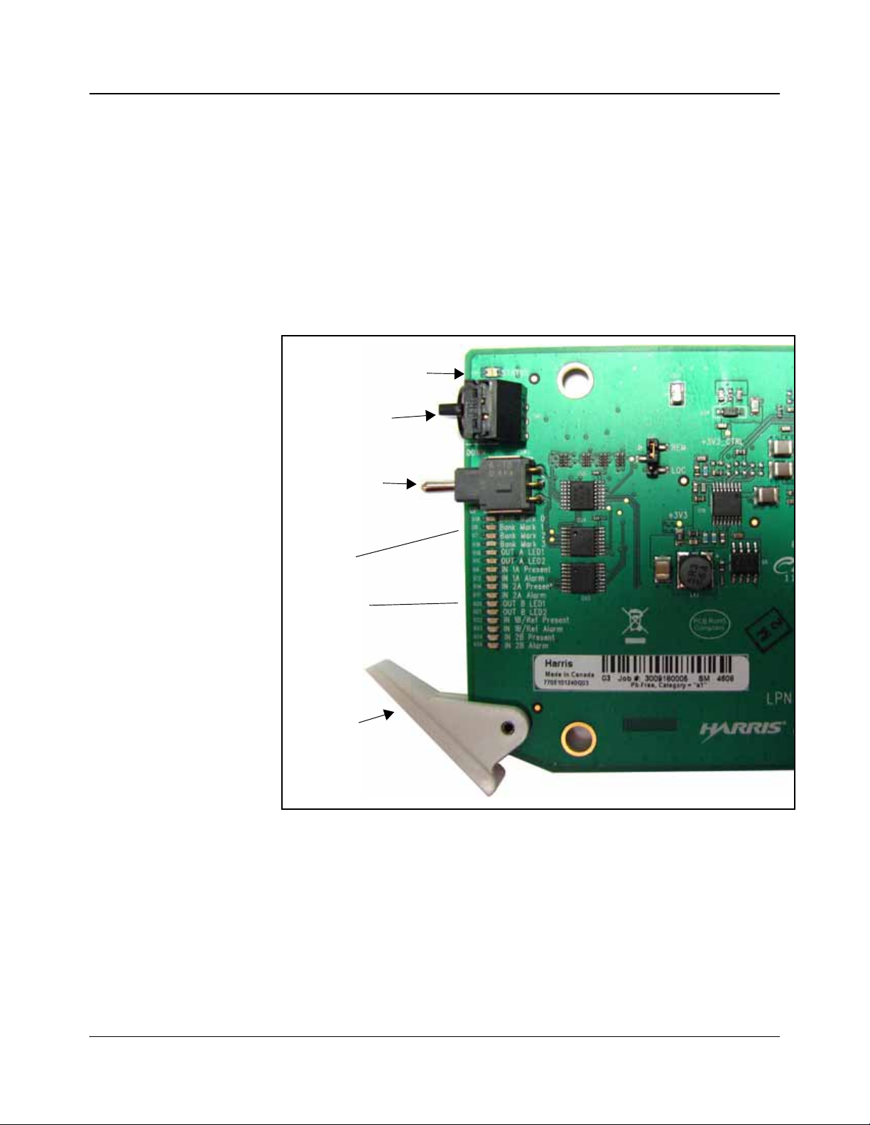
Module status LED
Mode select
rotary switch
Navigation
toggle switch
Monitoring
LEDs
Control
LEDs
Extractor
handle
Applications
Front Module
ACO6800+ modules allow broadcasters who must turn aro und large numbers of
signals (such as satellite direct-to home operations, cable head-ends, mobile
television operations, and IPTV operations) to provide two signal sources with
the ability to switch between the signals to play one on air.
Figure 1-1 shows the position of the LEDs and module controls on the front of
the modules.
4 ACO6800+ Installation and Operation Manual
Figure 1-1. Typical Module
Table 1-2 on page 5 briefly describes the LEDs, switches, and jumpers.
Copyright © 2009, Harris Corporation
Page 19

Table 1-2. Generic 6800+ Module Features
Feature Description
Chapter 1: Introduction
Module status
LEDs
Various color and lighting combinations of these LEDs indicate the
module state. See page 41, page 52, page 64, and page 99 for more
information.
Mode select
rotary switch
Navigation
toggle switch
This switch selects between various control and feedback
parameters.
This switch navigates up and down through the available control
parameters:
• Down: Moves down through the parameters
• Up: Moves up through the parameters
Control LEDs Various lighting combinations of these Control LEDs (sometimes
referred to as “Bank Select LEDs”) indicate the currently selected
bank. See “Bank Select LEDs” on page 19 for more information.
Monitoring
LEDs
Each 6800+ module has a number of LEDs assigned to indicate
varying states/functions. See page 42, page 53, page 65, and
page 100 for descriptions of these LEDs.
Jumpers This module has Remote/Local jumper, for selecting either local or
remote control of the module (default is Remote). The
BSCAN/Normal jumper must be left in the Normal position.
ACO6800+ Installation and Operation Manual 5
Copyright © 2009, Harris Corporation
Page 20
Chapter 1: Introduction
IN 2IN 1
OUT 2
OUT 1
AUX 2AUX 1
GENLOC K
GPI
BYPASS
IN 2
IN 1
OUT 2
OUT 1
IN 2IN 1
OUT 2
OUT 1
GPI A GPI B
A
B
BYPASS
BYPASS
IN 2IN 1
OUT 2
OUT 1
NOT USEDNOT USED
OUT 2
OUT 1
GPI A NOT USED
A
B
BYPASS
ACO6800+DSD/IDSD
ACO6800+ISCST
ACO6800+ISD/ASID
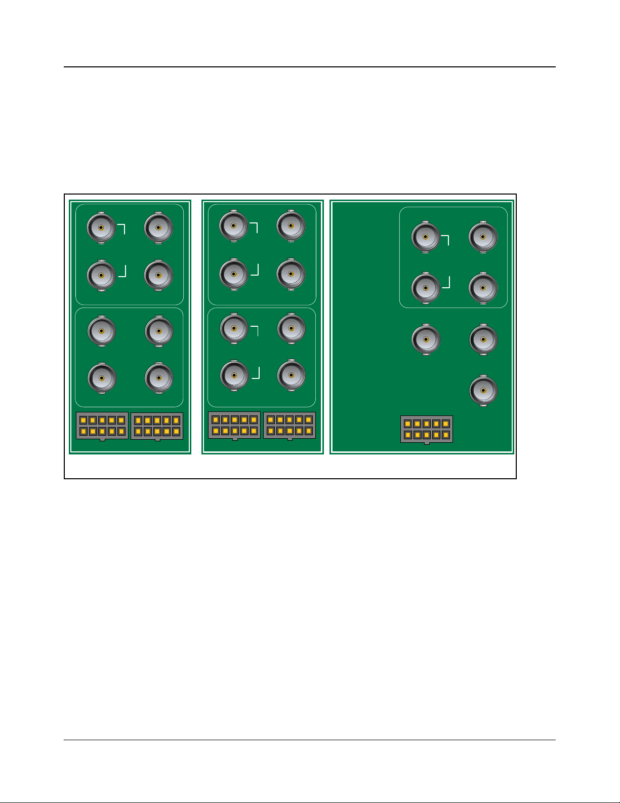
Back Modules
Figure 1-2 shows the double-slot back modules used by the ACO6800+ISD,
ACO6800+DSD, ACO6800+ASID, and ACO6800+IDSD modules, and the
triple-slot back module used by the ACO6800+ISCST module.
The back and front modules cannot be installed in frames witho ut fans, or in
FR6802+DM and 6800/7000 series frames.
Figure 1-2. ACO6800+ Back Modules
6 ACO6800+ Installation and Operation Manual
Copyright © 2009, Harris Corporation
Page 21
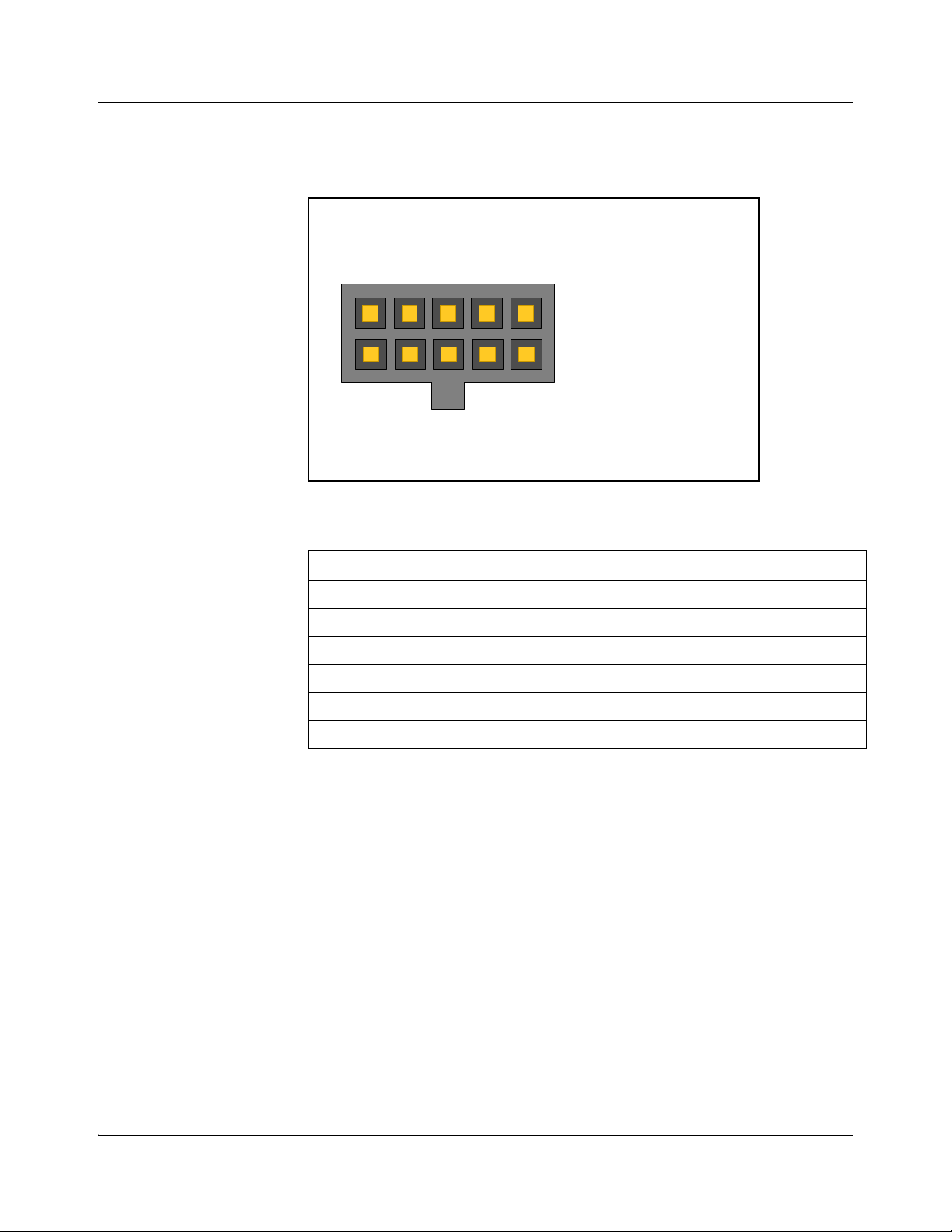
GPI Mating Connector
15
610
1. GPI In 1
2. Ground
3. GPI In 2
4. Ground
5. GPI In 3
6. GPI Out 1
7. Ground
8. GPI Out 2
9. Ground
10. GPI Out 3
The GPI Connector cable (provided) has the following connections:
Figure 1-3. GPI Connector Pinouts
Table 1-3. GPI Functions
Chapter 1: Introduction
ACO6800+ Installation and Operation Manual 7
Copyright © 2009, Harris Corporation
GPI Function
GPI In 1 Switch to IN 1
GPI In 2 Switch to IN 2
GPI In 3 Force relay to bypass signal IN 1
GPI Out 1 Indicate IN 1 is selected as output source
GPI Out 2 Indicate IN 2 is selected as output source
GPI Out 3 Indicate signal IN 1 is bypassed
Page 22
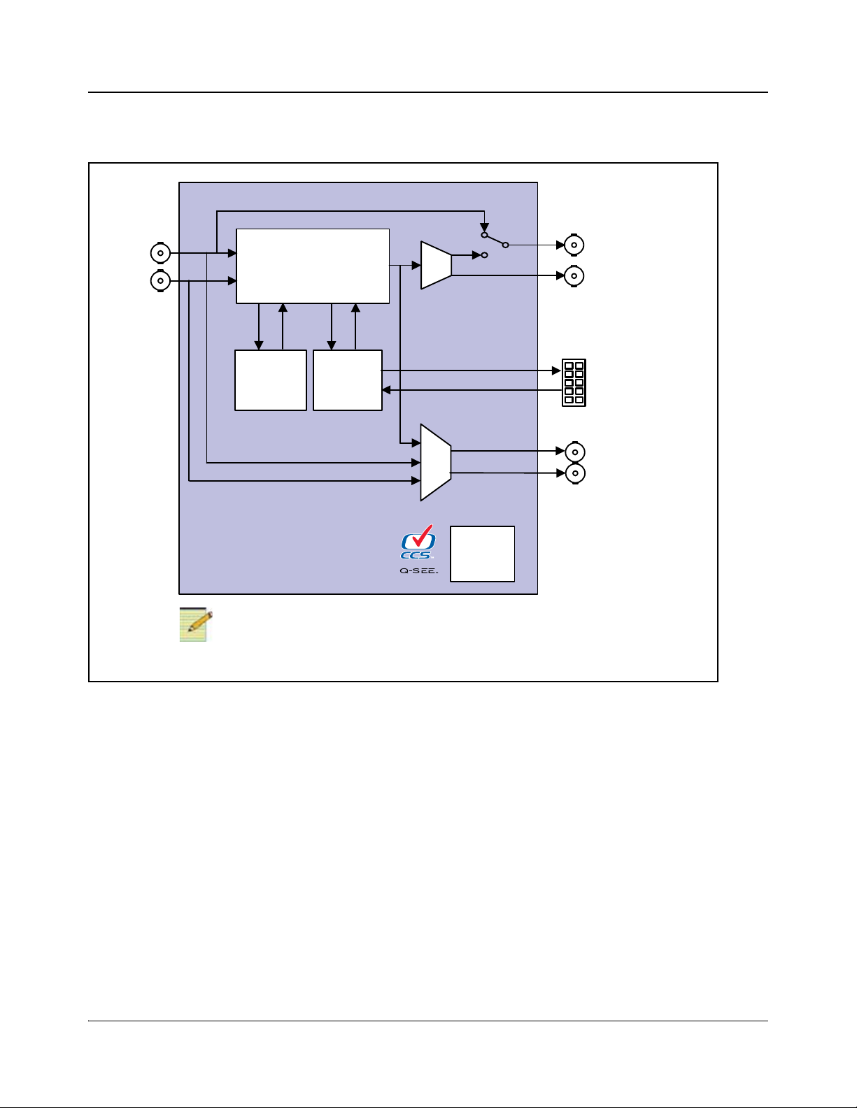
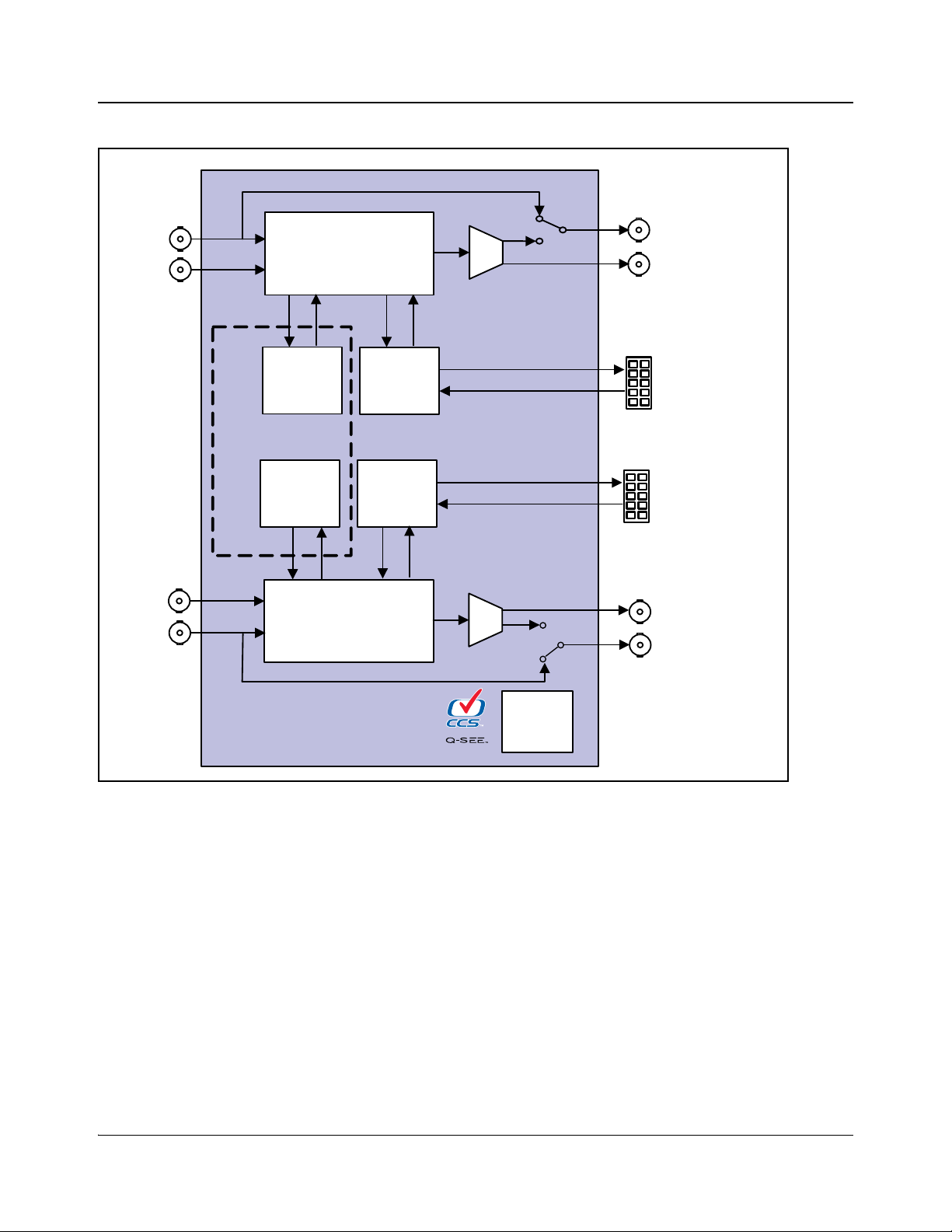
Chapter 1: Introduction
Switch
In 1A
Switch
logic
Q-SEE
logic
Out 1 B
Out 2B
CPU
Monitoring
and
Control
Out 1A bypass
Out 2A
In 2A
GPI in/out A
Note
ACO6800+ASID does not support thumbnails in the Q-SEE logic.
Signal Flow Diagrams
Figure 1-4. Signal Flow Diagram for ACO6800+ISD and ACO6800+ASID
8 ACO6800+ Installation and Operation Manual
Copyright © 2009, Harris Corporation
Page 23
Chapter 1: Introduction
Switch
In 1A
Switch
logic
Q-SEE
logic
Out 1B bypass
Switch
In 1B
Out 2 B
CPU
Monitoring
and
Control
Out 1A by pas s
Out 2A
In 2A
In 2B
GPI in/out A
Switch
logic
Q-SEE
logic
ACO6800+IDSD only
GPI in/out B
Figure 1-5. Signal Flow Diagram for ACO6800+DSD and ACO6800+IDSD
ACO6800+ Installation and Operation Manual 9
Copyright © 2009, Harris Corporation
Page 24
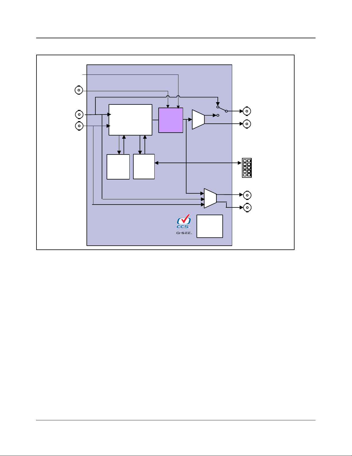
Chapter 1: Introduction
Switch
In 1
Switch
logic
Q-SEE
logic
AUX 2
AUX 1
CPU
Monitoring
and
Control
Out 1 bypass
Out 2
In 2
GPI in/out
Frame
and audio
sync
Trouble
slide/TSG
Genlock
Figure 1-6. Signal Flow Diagram for ACO6800+ISCST
10 ACO6800+ Installation and Operation Manual
Copyright © 2009, Harris Corporation
Page 25

Unpacking the Module
Note
Before you install the module, do the following:
• Check the equipment for any visible damage that may have occurred during
transit.
• Confirm receipt of all items on the packing list. See “Checking the Packing
List” on page 12 below for more information.
Contact your Customer Service representative if parts are missing or
damaged.
• Remove the anti-static shipping pouch, if present, and all other packaging
material.
Chapter 2
Installation
• Retain the original packaging materials for possible re-use.
See “Unpacking/Shipping Information” on page ix for information about
returning a product for servicing.
ACO6800+ Installation and Operation Manual 11
Copyright © 2009, Harris Corporation
Page 26

Chapter 2: Installation
Checking the Packing List
Table 2-1. Available Product Packages
Ordered Product Content Description
ACO6800+ISD
ACO6800+DSD
ACO6800+IDSD
ACO6800+ASID
ACO6800+ISCST
• One ACO6800+ front module
• One two-slot back module
• One ACO6800+ISD back module overlay
• One license key
• One GPIO cable
• One ACO6800+ISD/ACO6800+DSD/ACO6800+IDSD/
ACO6800+ASID/ACO6800+ISCST Installation and Operation Manual
• One ACO6800+
• One two-slot back module
• One ACO6800+DS/ACO6800+IDS back module overlay
• Two GPIO cables
• One license key
• One ACO6800+ISD/ACO6800+DSD/ACO6800+IDSD/
ACO6800+ASID/ACO6800+ISCST Installation and Operation Manual
• One ACO6800+
• One two-slot back module
• One ACO6800+DS/ACO6800+IDS back module overlay
• Two GPIO cables
• One license key
• One ACO6800+ISD/ACO6800+DSD/ACO6800+IDSD/
ACO6800+ASID/ACO6800+ISCST Installation and Operation Manual
• One ACO6800+ front module
• One two-slot back module
• One ACO6800+ASID back module overlay
• One GPIO cable
• One ACO6800+ISD/ACO6800+DSD/ACO6800+IDSD/
ACO6800+ASID/ACO6800+ISCST Installation and Operation Manual
• One ACO6800+ front module
• One three-slot back module
• One submodule
• One GPIO cable
• One license key
• One Icon SoftTools CD (wi th LogoCreator)
• One ACO6800+ISD/ACO6800+DSD/ACO6800+IDSD/
ACO6800+ASID/ACO6800+ISCST Installation and Operation Manual
front module
front module
12 ACO6800+ Installation and Operation Manual
Copyright © 2009, Harris Corporation
Page 27

Maximum 6800+ Frame Power Ratings
Note
Note
The power consumption for the ACO6800+ISD, ACO6800+DSD,
ACO6800+ASID, and ACO6800+IDSD 2-slot modules is less than 12 W. The
power consumption for the three-slot ACO6800+ISCST module is less than 13
W. Table 2-2 shows the maximum allowable power ratings for 6800+ frames.
Note the given maximums before installing any 6800+ modules in your frame.
Due to high levels of heat dissipation, the modules should not be installed in
frames without fans. The modules cannot be installed in FR6802+DM and
6800/7000 series frames.
To maintain proper temperatures, ensure that the front panel is closed at all
times, and that the fan module is fully operational.
Table 2-2. Maximum Power Ratings for 6800+ Frames
Chapter 2: Installation
6800+ Frame
Type
FR6802+QXF
Max. Number of
Max. Frame
Power
Dissipation
Max Power
Dissipation
for Two
Slots
Max Power
Dissipation
for Three
Slots
ACO6800
ACO6800+DSD/
ACO6800+ASID/
ACO6800+IDSD
Modules
120 W 12 W 18 W 10 6
+ISD/
*
Max. Number of
ACO6800
Modules
(frame with AC or
DC power supply)
FR6802+XF
120 W 12 W 18 W 10 6
(frame with AC
power supply)
FR6802+XF-48
105 W 10.5 W 15.25 W 9 6
(frame with DC
power supply)
FR6822+
120 W 12 W 18 W 10 6
(frame with AC or
DC power supply)
* The power consumption of
ACO6800+ISD, ACO6800+DSD, ACO6800+ASID, and
ACO6800+IDSD, listed as <12 W, is measured at around 11.5 W.
† The power consumption of ACO6800+ISCST, listed as <13 W, is measured at around 12.5 W.
+ISCST
†
ACO6800+ Installation and Operation Manual 13
Copyright © 2009, Harris Corporation
Page 28

Chapter 2: Installation
Caution
Caution
Note
Note
Installing the Modules
Due to high levels of heat dissipation, the modules must not be installed in
frames without fans. The modules cannot be installed in FR6802+DM or
6800/7000 series frames.
These modules require no specialized installation or removal procedures.
However, if you are installing b oth front module and back connector , ensure that
the back connector is installed first before plugging in the front module.
Likewise, ensure that the front module is unplugged from the frame before
removing the back connector. See the installation and operation manual for your
frame for information about installing and operating the frame and its
components.
Use the FR6802+RM (Rear Support Extension Rails for 6800+ series frames)
for the modules. See the installation and operation manual for your frame for
installation instructions.
Before installing this product, read the 6800+ Series Safety Instructions and
Standards Manual shipped with every frame installation and operation
manual. This information is also available on our website. The safety
manual contains important information about the safe installation and
operation of 6800+ series products.
Upgrading Module Firmware
Firmware upgrading is a routine procedure that you must perform to install
newer versions of software on 6800+ modules. Navigator software version 4.4
or later is required to perform this procedure on ACO6800+ modules. The
frame must contain or be connected to another frame that contains an ICE6800+
or a 6800+ETH module, version 4.1 or higher.
You can upgrade your 6800+ module’s firmware using the Software Upgrade
tool in CCS Navigator 4.4 or higher. See your frame manual for more
information.
The File Transfer tab is not meant to be used for firmware upgrades. Use
the Software Upgrade tool to upgrade module firmware.
If you do not use the correct firmware version, your module may display
incorrect menu structures, thumbnail failures, and software upgrade failures.
The module uses high-speed upgrading in ASI mode, and normal field
upgrading in SDI mode.
14 ACO6800+ Installation and Operation Manual
Copyright © 2009, Harris Corporation
Page 29

Network Control
For detailed information on how to operate this product remotely, see the
Navigator, NUCLEUS Network Control Pan el, or LCP-3901-1 U/RCP-CCS-1U
manual for Ethernet interface.
ACO6800+ modules do not support + Pilot Lite software; however , you can use
HTTP or SNMP monitoring and control. For detailed information, see the
installation and operation manual for your frame.
Chapter 3
Configuration and Operation
ACO6800+ Installation and Operation Manual 15
Copyright © 2009, Harris Corporation
Page 30

Chapter 3: Configuration and Operation
Note
Operating Notes
When you set the control parameters on the ACO6800+, observe the following:
• If you make changes to certain parameters, other related parameters may
also be affected.
• When you change a parameter, the effect is immediate. However, the
module requires up to 20 seconds to save the latest change. After 20
seconds, the new settings are saved and will be restored if the module loses
power and must be restarted.
• For best results, terminate any unused coaxial output connectors with a 75Ω
connector.
Adding a License Key
ACO6800+ISD, ACO6800+DSD, and ACO6800+IDSD modules can be
converted to one another through use of a license key. It is not possible to
upgrade to an ACO6800+ISCST or ACO6800+ASID module.
For assistance with a license key , or to purchase a license key, contact your
Sales representative. See “Checking the Packing List” on page 12.
To enter a license key, your CCS software must be in Control mode. Follow
these steps:
1. Select the ACO6800+ module in the Navigation pane.
2. Right-click, and then select Control to open the module’ s Control window.
3. If it is not already selected, click on the Parameters tab.
4. Select General in the tree view, and then type your license key in the
License Key field.
If your license key is valid, the Installed Options field displays the features that
are activated on the module.
16 ACO6800+ Installation and Operation Manual
Copyright © 2009, Harris Corporation
Page 31

Changing Parameter Settings
Note
You can control the ACO6800+ modules at the card edge, or by using
CCS-enabled hardware and software applications.
ACO6800+ASID does not use card-edge controls.
CCS Navigator
Before using CCS Navigator to change your module’s parameter settings, you
must discover the module. Discovery is the process by which your software
finds, and then connects to your module.
Discovering a Module
T o discover your mod ule, your CCS Navigator software must be in Build mode.
Follow these steps:
1. If the Discovery pane is not open, select Tools > Discovery in the main
menu.
A Discovery pane opens, most likely in the bottom left corner of the screen.
2. Click Options, and then click Add.
Chapter 3: Configuration and Operation
3. Enter the IP address of the frame that contains your module, the frame that
contains your ICE6800
module that provides access to your module.
4. Click OK, and then OK again to close the Discovery Options dialog box.
5. Click Start.
This causes Navigator to run a discovery.
6. When your discovery is complete, Discovery Completed is displayed in
the Discovery pane. To continue, click Save, to save the contents of your
discovery to the Discovery folder of the Navigation pane.
+ module, or the frame that contains a 6800+ETH
ACO6800+ Installation and Operation Manual 17
Copyright © 2009, Harris Corporation
Page 32

Chapter 3: Configuration and Operation
Note
Note
ACO6800+ISD,
ACO6800+ASID, or
ACO6800+ISCST
ACO6800+DSD or
You can now switch to Control mode by selecting Operational Mode >
Control from the main menu. Double-click ACO6800+ in the Navigation pane.
The Control dialog box opens displaying the module’s controls.
Confirm that the four sub-devices (for ACO6800+DSD, ACO6800+ASID, or
ACO6800+IDSD) or two sub-devices (for ACO6800+ISD and
ACO6800+ISCST) are also discovered, as in Figure 3-1. If the sub-devices
are not discovered, re-discover the module.
Figure 3-1. Discovery of ACO6800+ Modules in CCS Navigator
Card-Edge Controls
Using the module’ s rotary and navigation switches, you can change ACO6800 +
parameter settings at the card edge. You can view and confirm your changes
using the On-screen display feature (see “Activating On-Screen Display” on
page 19).
Card-edge controls are not available for ACO6800+ASID modules.
1. Rotate the mode select rotary switch (hex switch) to “0.”
2. Once the hex switch is set to “0,” toggle the navigation switch up or down
to select a bank.
View the four control LEDs next to the navigation toggle switch to see
which bank is currently selected.
18 ACO6800+ Installation and Operation Manual
Copyright © 2009, Harris Corporation
Page 33

Note
Note
Table 3-1. Bank Select LEDs
Chapter 3: Configuration and Operation
Bank Number
0 Off Off Off Off
1 On Off Off Off
2 Off On Off Off
3On OnOffOff
4OffOffOnOff
5OnOffOnOff
6 Off On On Off
7On OnOnOff
8 Off Off Off On
Bank 0 LED
(first top LED)
3. Rotate the hex switch to the parameter number (1 to 9) or letter (A to F) of
4. Toggle the navigation switch to select and set the value of the chosen
5. Do either of the following:
Bank 1 LED
(second top LED)
Bank 2 LED
(third top LED)
Bank 3 LED
(fourth top LED)
the option you want to set.
parameter.
• Rotate the hex switch to another parameter number/letter in the current
bank, and then repeat step 4.
Throughout this chapter, in the Parameter Navigation sections, the bank and hex
switch positions for each configuration setting are listed in square brackets (for
example, [0, 2]) beside or below the parameter name.
Activating On-Screen Display
You can use the On-Screen Display (OSD) Monitoring feature to view the
current parameter selections on your output display. This feature makes
configuring the ACO6800+ using the card-edge controls much easier.
• Rotate the hex switch to “0” again to select a different bank, and then
repeat steps 3 and 4.
The manufacturer recommends that you use the available 6800+ software
control options (serial/local or Ethernet/remote) to aid in viewing, setting,
and confirming parameter values.
In ACO6800+ISD, ACO6800+DSD, and ACO6800+IDSD modules, OSD is
only displayed on Out A. In ACO6800+ISCST, OSD can be displayed on
any one of the four outputs. OSD is not available in ASI mode. OSD is not
available on ACO6800+ASID modules.
ACO6800+ Installation and Operation Manual 19
Copyright © 2009, Harris Corporation
Page 34

Chapter 3: Configuration and Operation
Note
Note
OSD will only appear when the option is enabled. The module must be in SDI
mode for OSD to appear correctly. On ACO6800+DSD and ACO6800+IDSD
modules, the Output Source must be from Group A.
Table 3-2 lists the parameters to set to activate OSD.
Table 3-2. Activating OSD
Parameter Name
Function Options
Bank,
Switch
ACO6800+ISD, ACO6800+DSD, and ACO6800+IDSD
ACO Group A > MISC Settings
OutA OSD Enable 1, 4 Activates the on-screen display on Out A outputs
ACO6800+ISCST
Video > Out 1_2 Settings
OSD Enable 5 C Activates the on-screen display on PGM outputs
Video > AUX Settings
AUX OSD Enable 5, E Activates the on-screen display on AUX outputs
Recalling Default Parameter Settings
You can use the module’s Factory Recall parameter under System Config to
return all of the module’s parameters to factory default settings. In the
ACO6800+ control parameter list (see page 35, page 47, page 57, and page 85),
each factory default setting appears in bold.
To return this module to its default settings, set the Factory Recall parameter
(0, F) to Enable.
• Enable
• Disable
• Enable
• Disable
• Enable
• Disable
There are two independent sets of d efault values, one for SDI mode and the
other for ASI mode. Factory Recall in SDI mode will not affect the
parameters in ASI mode; nor will Factory Recall in ASI mode affect the
parameters in SDI mode. This does not apply to ACO6800+ASID.
Q-SEE-Compliant Thumbnails
The ACO6800+ASID does not support Q-SEE compliant thumbnails.
20 ACO6800+ Installation and Operation Manual
Copyright © 2009, Harris Corporation
Page 35

Chapter 3: Configuration and Operation
Note
ACO6800+ modules support Q-SEE compliant thumbnails. To use Q-SEE
compliant features, the following conditions must be met:
• The modules must be installed in an FR6802+QXF frame that also contains
a 6800+ETH module (firmware version 4.0 or higher) or an
FR6822
• You must use CCS Navigator version 4.4 or later.
When you open a Control window in CCS Navigator for the 6800+ETH
module, all Q-SEE compliant modules provide thumbnails on a Video
Streaming tab. In addition, the ACO6800+ module Control dialog box has a
Streaming tab where a thumbnail is displayed and updated at up to three frames
per second.
Q-SEE-compliant thumbnails are available for all inputs and outputs, but only
one can be viewed at a time.
If thumbnails do not appear correctly, refresh the tab. To ensure that thumbnails
are operating correctly on your system, view the thumbnail in the 6800
module’s Control dialog bo x.
For more information on Q-SEE compliant thumbnails, see the installation and
operation manual for your frame.
+QXFE frame.
+ETH
Relay Bypass
When Group A or Group B Relay Bypass is activated, Out 2 goes blank, and
the thumbnail and OSD are not available.
Group A or Group B Relay Bypass can be triggered in the following
situations:
• Power failure
•The Group A or Group B GPI In Trigger Level parameter is set to Active
High while nothing is connected to the connector (the Relay Bypass is
triggered because of the internal pull-up on this port)
•The Group A or Gr oup B GPI In Trigger Level parameter is set to Active
Low while the external GPI Input 3 is low
•The Group A or Group B Relay Bypass parameter is set to On.
As soon as the command is accepted (by GPI Input or by Group A or Group B
Relay Bypass parameter), the signal IN 1 is bypassed regardless of switching
mechanism.
If the Group A or Group B Relay Status parameter is shown to be Off
while the relay is actually working, the relay on the card may be damaged.
Passing Dolby Audio (ACO6800+ISCST Modules Only)
To properly process Dolby audio embedded in the video signal, the following
requirements must be met:
ACO6800+ Installation and Operation Manual 21
Copyright © 2009, Harris Corporation
Page 36

Chapter 3: Configuration and Operation
Note
•The Sync Mode Set parameter must be set to Genlock.
• Genlock must be available, with a frame rate that matches the operation
standard.
• Input video must be synced to Genlock.
•The SRC (1-8) Bypass parameter must be set to Yes.
If the SRC Bypass Mode parameter is set to Auto, ACO6800+ will enable
SRC bypass automatically when Dolby data is detected.
Configuring the Switching Mechanism
Three factors control the output channels on the ACO6800+:
•GPI control
• Alarm severity levels for each input channel
• Parameters that can be manually switched in CCS Navigator or at the card
edge
Use the following parameters in the Switch Settings group of parameters to
define the switch priority levels:
• Group A or Group B Switch High Priority (the default setting is GPI Input)
GPI Input Control
• Group A or Group B Switch Medium Priority (the default setting is
Manual)
• Group A or Group B Switch Low Priority (the default setting is Alarms)
A high priority event overrides a medium priority event, which overrides a low
priority event. The three options are mutually exclusive.
As an example, the current settings might start out in these default values:
• Group A Switch High Priority: GPI Input
• Group A Switch Medium Priority: Manual
• Group A Switch Low Priority: Alarms
By changing the Group A Switch Low Priority setting to GPI Input, the
module automatically changes the Group A Switch High Priority setting to
Alarms. This new setting is exclusive, and will not conflict with the Medium
and Low settings.
Table 3-3 indicates what happens when a GPI Input is activated—for example,
pressing a button on a panel—when the switching is not triggered by other
higher priority events than GPI Input.
22 ACO6800+ Installation and Operation Manual
Copyright © 2009, Harris Corporation
Page 37

Table 3-3. GPI Input Control
GPI Action/Result
GPI 1 Switches output source to IN 1
GPI 2 Switches output source to IN 2
Manual Control
When the switching is not triggered by other higher priority events, you can use
the parameters described in Table 3-4 to manually switch the source using either
CCS Navigator or the card-edge controls.
Table 3-4. Manual Switch Parameters
Chapter 3: Configuration and Operation
Parameter Name
ACO6800+ISD
Group A Manual Switch 1, E Sets the output source when a channel is
ACO6800+DSD and ACO6800+IDSD
Group A Manual Switch 1, E Sets the output source when a channel is
Group B Manual Switch 4, E Sets the output source when a channel is
ACO6800+ASID
Manual Switch n/a Sets the output source when a channel is
ACO6800+ISCST
Manual Switch 1, E Sets the output source when a channel is
Function Options
Bank,
Switch
switched manually
switched manually
switched manually
switched manually
switched manually
• Disable
• Switch to A1
• Switch to A2
• Disable
• Switch to A1
• Switch to A2
• Disable
• Switch to B1
• Switch to B2
• Disable
• Switch to 1
• Switch to 2
• Disable
• Switch to A1
• Switch to A2
ACO6800+ Installation and Operation Manual 23
Copyright © 2009, Harris Corporation
Page 38

Chapter 3: Configuration and Operation
Note
Alarm Control
The combination of the switch priority parameter settings, adjustable alarm
switch levels, and SQM smart alarms on the subdevice of the ACO6800+
module provides flexible automatic and manual switch control. In the case of
the SQM smart alarms, you can individually adjust the severity and trigger/clear
duration for each alarm type (for more information, see page 43, page 54,
page 66, and page 101). The following tables offer two sample scenarios.
By default, all alarms are set to a disabled state. To configure a device to
switch using alarms as a trigger, first enable alarms in the sub-device.
Failure of Auto/Manual switchover
If your auto/manual switchover does not work as expected, confirm that the
following parameters have been configured correctly:
• Group (A/B) GPI Input_(1-3) should confirm the GPI Input condition.
• Group A or Group B Manual Switch should confirm the expected setting.
• Group A or Group B Switch (High/Medium/Low) Priority should
display the sort of logic seen in Table 3-6 and Table 3-8.
• Group A or Group B Alarm Switch Level should confirm the triggered
level.
Confirm that the configurable portions of sub-device alarms match your
expectations. (This includes Enable/Disable, Alarm Priority, Trigger Time, and
Clear Time.)
For ACO6800+ISCST modules, ensure that the Video Standard and
Operation Standard parameters have the same setting. The Still Image Mode
parameter must be set to Auto, and the Force Free z e an d For ce Black
parameters must be set to Off.
Sample Scenario One
The initial settings for sample scenario one are outlined in Table 3-5.
Table 3-5. Sample Scenario One: Parameter Settings
Parameter Setting
Group A Switch High Priority GPI Input
Group A Switch Medium Priority Manual
Group A Switch Low Priority Alarms
Group A Alarm Switch Level 6
Group A Manual Switch Disable
24 ACO6800+ Installation and Operation Manual
Copyright © 2009, Harris Corporation
Page 39

Chapter 3: Configuration and Operation
Table 3-5. Sample Scenario One: Parameter Settings
Parameter Setting
A1 SDI Loss of Video: Priority 6
A1 SDI Loss of Video: Trigger 2 s
A1 SDI Loss of Video: Clear 10 s
Table 3-6. Sample Scenario One: Chain of Events
Event Result
1. At the start, A1 and A2 are both present.
Output A is A1 (A1 is the primary channel).
2. A1 is lost.
3. Two seconds pass.
4. A user sets the Manual Switch to A1.
5. A user activates GPI Input 2.
6. A user sets the Manual switch to
Disable.
7. A1 is present.
8. Five seconds after A1 is present, GPI
Input 2 is deactivated.
9. Five seconds pass.
Sample Scenario Two
The initial settings for sample scenario two are outlined in Table 3-7. For this
scenario, the trigger time and clear time of all alarms is presumed to be 0
seconds.
Table 3-7. Sample Scenario Two: Parameter Settings
Output A is A1 (alarm is not yet triggered;
waiting for two second trigger condition).
Output A is A2 (alarm is triggered).
Output A is A1 (Manual has higher priority
than Alarm).
Output A is A2 (GPI Input has higher priority
than Manual).
Output A is A2.
Output A is A2 (GPI Input command is still
active).
Output A is A2 (alarm for A1 is not cleared
yet; waiting for 10 seconds clear condition).
Output A is A1 (alarm is cleared).
Parameter Setting
Group A Switch High Priority GPI Input
Group A Switch Medium Priority Alarms
Group A Switch Low Priority Manual
Group A Alarm Switch Level 6
Group A Manual Switch Disable
A1 SDI Loss of Video: Priority 6
A1 SDI Video Standard Mismatch: Priority 1
ACO6800+ Installation and Operation Manual 25
Copyright © 2009, Harris Corporation
Page 40

Chapter 3: Configuration and Operation
Table 3-7. Sample Scenario Two: Parameter Settings (Continued)
Parameter Setting
A1 SDI Expected Standard 525
A2 SDI Video Standard Mismatch: Priority 6
A2 SDI Expected Standard 525
Table 3-8. Sample Scenario Two: Chain of Events
Event Result
1. At the start, A1 and A2 are both
2. A1 is lost.
3. A user sets the Manual Switch to
present and 625 format.
A2.
Output A is A1 (A1 Standard Mismatch alarm is
on, but has not met switching condition, level 6).
Output A is A1 (A1 and A2 inputs are bad, but A2
Standard Mismatch alarm level is 6, so the
ACO6800+ selects primary input as output).
Output A is A1 (A2 is still bad, and Alarm has
higher priority than Manual).
4. A user activates GPI Input 2.
5. A user deactivates GPI Input 2.
6. A1 is present, 625 format.
Output A is A2 (GPI Input has higher priority than
Alarm).
Output A is A1.
Output A is A1 (Alarm is still on, but it has not
met switching condition).
Switching to a Still Image (ACO6800+ISCST Modules Only)
In ACO6800+ISCST modules, the Still Image Source parameter determines
whether the output is to TSG or trouble slide.
When the Still Image Mode parameter is set to Force, the output is to a
pre-defined still image, except when relay bypass is enabled.
When the Still Image Mode parameter is set to Auto, the still image is treated
as the module’s third input, which is always in good quality. The switching
mechanism includes the still image in its priority list. The order of priority, from
highest to lowest, is IN 1, IN 2, and still image.
Table 3-9 shows the relationship between switch mechanism and still image
output when the Still Image Mode parameter is set to Auto.
Table 3-9. Still Image Priority and Image Output When Still Image Mode is set to Auto
Switch High
Priority
Switch Medium
Priority
Switch Low
Priority
Output
Source
Note
GPI Input Select
IN1
GPI Input =
Inactive
26 ACO6800+ Installation and Operation Manual
N/A N/A Input 1 GPI forces IN 1 as output
source even when IN1 is
lost.
Manual Switch =
IN_2
N/A Input 2 Manual switch forces IN 2
as output source, even
when IN 2 is lost.
Copyright © 2009, Harris Corporation
Page 41

Chapter 3: Configuration and Operation
Table 3-9. Still Image Priority and Image Output When Still Image Mode is set to Auto
Switch High
Priority
GPI Input =
Inactive
GPI Input =
Inactive
Switch Medium
Priority
Manual Switch =
Disable
Manual Switch =
Disable
Switch Low
Priority
Alarm = Enable and
Alarm switch
condition met for
both inputs
Alarm = Disable Input 1 Switch Mechanism is
Output
Source
Still Image Switch Mechanism selects
Note
Still Image as output
source.
disabled.
Table 3-10 shows what happens when both inputs are lost and the SDI Loss of
Video alarm of both IN 1 and IN2 are considered as fatal alarms and triggered
(supposing GPI Input and Manual Switch are both not active).
Table 3-10. Still Image Output on ACO6800+ISCST Modules
Still Image
Mode
*
Auto
Auto TSG/Trouble Slide Black The output turns black, and then switches over
Auto TSG/Trouble Slide Freeze The output freezes the last good frame or field,
Auto Non e Pass The output passes some noise.
Still Image
Source
TSG/Trouble Slide Pass The output temporarily passes some video
LOV Mode Result
noise, and then switches over to the still image.
to the still image.
and then switches over to the still image.
†
Auto Non e Black The output switches to black signal.
Auto Non e Freeze The output freezes the last good frame or field.
* If the Still Image Mode parameter is set to Force, TSG/Trouble Slide is always on-line regardless of
signal quality of inputs.
† ACO6800+ cannot pass video with a different standard than the operation standard.
Creating Trouble Slides
Integrated Graphics Storage and Playout
The ACO6800+ISCST provides on-demand insertion of pre-defined static
SD-SDI and HD-SDI logo images.
ACO6800+ Installation and Operation Manual 27
Copyright © 2009, Harris Corporation
Page 42

Chapter 3: Configuration and Operation
Logo Insertion on the ACO6800+ISCST
Existing logo
graphic with
alpha channel
Conversion to
.mg2 format using
LogoCreator
Storage of logo file
on a microSD card
via the USB port on
a PC
Loading of file into
ACO6800+ISCST
module for on-air use
Logos used by the ACO6800+ISCST must be created or saved in the .mg2 file
format, and initially stored on a micro-SD card that is inserted into the slot
located at the card edge of the module. The ACO6800+ISCST supports
SanDisk, LEXAR, and Kingston 1G and 2G microSD cards.The files must be
loaded onto the card directly at your PC workstation. (LogoCreator software is
provided as a utility to convert existing files to .mg2).
Figure 3-2. Progression of Logo to On-Air Signal
The files that you use as logos must be selected according to the video output
standard set on the ACO6800+ISCST (System > Operation Standard). When
the output standard changes on the module, the ACO6800+ISCST
automatically loads files that use the selected output standard.
Basic Steps to Installing Logo Files
If you are starting with existing graphics files, these basic steps are as follows:
1. Install the LogoCreator conversion software from the IconSoft Tools
CD-ROM.
2. Convert the logos to an .mg2 format.
3. Transfer the files to the microSD card directly from the PC.
Step 1: Install LogoCreator Software
All logos used by the ACO6800+ISCST must either be generated as .mg2 files
or converted to that format. A version of LogoCreator (located on the IconSoft
Tools CD-ROM) is provided with the manual for this purpose.
For best results, LogoCreator requires a PC with the following system
specifications:
• Intel Pentium III processor at 500 MHz or faster
• 512 MB or more of physical memory (RAM)
• Microsoft
If a version of LogoCreator already exists on the PC, ensure that you first
uninstall the program and restart the computer. Then, proceed with the steps
below:
®
Windows® XP or Windows 2000
1. Close all other software applications running on the PC and then insert the
IconTools CD-ROM into the computer’s CD-ROM tray.
28 ACO6800+ Installation and Operation Manual
Copyright © 2009, Harris Corporation
Page 43

2. Using Windows Explorer, browse to the CD-ROM contents, and then
Note
double-click the LogoCreator folder.
3. Double-click Setup.exe.
4. When the IconTools 3 Setup box appears, click Next, and then follow the
on-screen installation instructions.
Step 2: Convert Files to the .mg2 Format
When using LogoCreator, you need a source image file for the fill portion of
your logo, and a source image file for the key portion. The fill is the picture or
image you want to overlay onto the program output. The key is the cutout or
shape of the desired logo, which may or may not be the same shape as the fill.
Use LogoCreator to set the fill and key images to the same size (resolution) as
the standard of the ACO6800+ISCST output. LogoCreator infers the key from
the alpha channel in a targa (.tga) file.
After you save the logo, the logo displays in your LogoCreator workspace. To
save your logo files using LogoCreator, follow these steps:
1. In LogoCreator, open the Logo Set-Up dialog box (Figure 3-3 below).
When you first open LogoCreator, the Logo Set-Up dialog box opens
automatically . If the Logo Set-Up dialog box is closed, select File > New to
open the dialog box.
Chapter 3: Configuration and Operation
Figure 3-3. LogoCreator Setup Dialog Box
If you click the Open button directly in the Logo Set-Up box, the
program will only launch files with a .mg2 prefix. If you attempt to open
a file with any other prefix, the program will generate error messages.
2. Click the Logo button to open the Static Logo dialog box.
3. Use the Logo ID box to assign the logo to a specific slot on your IconLogo
system.
4. Enter a name for the logo in the Name box.
ACO6800+ Installation and Operation Manual 29
Copyright © 2009, Harris Corporation
Page 44

Chapter 3: Configuration and Operation
Note
5. Click the Open button below the Logo Image Preview windo w.
6. Select your existing logo file and click the Open button to open the logo in
The Open dialog box displays.
the Static Logo dialog box.
Figure 3-4. Static Logo Dialog Box
• A preview of the composited logo displays in the Logo Image Preview
area.
• A preview of the image alpha displays in the Logo Alpha Preview area
if the file contains alpha.
7. Select a file to use as the alpha channel for your logo.
You must select a file before you can save the logo.
• T o use the original image’s alpha channel, select the Use the alpha key
found with image checkbox.
• To use a different image for the alpha channel, clear the Use the alpha
key found with image checkbox, and then click the Open button to
select a new file for your alpha channel.
An alpha channel is an 8-bit layer in a graphics file format that expresses
transparency. Typically, you define the alpha channel on a per-object basis.
Different parts of an object will have different levels of transparency
depending on how much background you want to show through.
8. Click the Save button in the Static Logo dialog box.
The Save Logo File dialog box opens. In this dialog box, you can save your
logo as a .mg2 file. Once you save the logo as a .mg2 file, the logo displays
in the LogoCreator workspace.
30 ACO6800+ Installation and Operation Manual
Copyright © 2009, Harris Corporation
Page 45

Figure 3-5. LogoCreator Work Space
Chapter 3: Configuration and Operation
Once you create an .mg2 logo, you can
• Open the file in LogoCreator
• Set the logo position
• Modify specific logo attributes
LogoCreator also makes it possible to adjust the noise and strength of the
key signal and apply fade on/off transitions to the logo.
Step 3: Transfer the Logos to the MicroSD Card
When your logos have been created or converted to the .mg2 format, they can
be saved on the microSD card. The ACO6800+ISCST references files on the
MicroSD card using the DOS 8.3 short filename convention. Longer filenames
may be accessed by entering the alternate 8.3 filename. To avoid any confusion,
it is preferable to limit all filenames to the 8.3 format, with a maximum of 8
characters before the .mg2 extension.
ACO6800+ Installation and Operation Manual 31
Copyright © 2009, Harris Corporation
Page 46

Chapter 3: Configuration and Operation
MicroSD card
in socket
In addition, all files must be located within the logos folder on the microSD
card. Figure 3-6 shows the location of the microSD socket.
Figure 3-6. Inserting the MicroSD Card
Using Trouble Slides
The Trouble Slide Source parameter has four options. The Trouble Slide
(1/2/3) options are only available when there are compatible trouble slides
(MG2 format) stored in the microSD card.
The trouble slide can have two sources:
• Default trouble slides are stored within the firmware of the ACO6800+.
• Up to three user trouble slides can be stored in a microSD card (located at
Trouble slides must meet the following criteria:
You can only change the background portion of default trouble slides (using
parameter Trouble Slide Background)
the sub-module)
32 ACO6800+ Installation and Operation Manual
Copyright © 2009, Harris Corporation
Page 47

Chapter 3: Configuration and Operation
• The SD card must be microSD, formatted as FAT/FAT16 (FAT32 is not
supported). Suppliers SANDISK, LEXAR and Kingston, memory size 1G
and 2G have been verified. Figure 3-7 shows a valid SD card in a PC
browser window.
Figure 3-7. Valid SD Card in Browser Window
• The image file must be put in folder named “logos” in the root directory
(regardless of uppercase or lowercase).
• The image file must be MG2 format with extended name “mg2” or “MG2”.
• The width and height of mg2 file must be smaller than the supported size of
current operation standard (for example, if the current operation standard is
720p, and the video size is 1280*720, if the image size is 720*576, it is
acceptable. If it is 1920*1280, it would be refused).
• For best results, the length of file name should be less or equal to 8 letters.
(If the length of mg2 file name is larger than 8 characters, a shortened name
will display on Navigator.)
• Only the first three valid MG2 files sorted by access time are displayed on
Navigator.
• For best results, the original image (before converting to MG2 format)
should consist of an even number of pixels and an even number of lines.
• Every time the operation standard or trouble slide background changes, the
system reloads the trouble slide.
Generally, larger or more complicated images take longer for the system to
load. A complicated image with size of 1920*1280 (the maximum supported
size) takes about 7 minutes to finish loading. The trouble slide will not be
displayed until loading is finished (it is masked as black during that time).
ACO6800+ Installation and Operation Manual 33
Copyright © 2009, Harris Corporation
Page 48

Chapter 3: Configuration and Operation
34 ACO6800+ Installation and Operation Manual
Copyright © 2009, Harris Corporation
Page 49

ACO6800+ISD Parameters, LEDs, and
On-Screen Display Monitoring
If you are using card-edge controls to configure your ACO6800+ISD module,
you can use the on-screen display (OSD) monitoring feature to view the current
parameter selections. When the OSD monitoring is activated, the current
parameter selections are displayed on module’s monitoring outputs. For
information on enabling OSD monitoring, see “Activating On-Screen Display”
on page 19.
Parameter Table Notes
When you look at the control parameter tables, note the following:
• Shaded table rows and [RO] after the parameter name indicate read-only
(feedback) parameters.
• Bolded parameter options indicate the default settings for the parameter.
• The bank selection and rotary switch combinations for each parameter and
parameter option are listed in the tables under the Bank, Switch heading.
For more information about using the card-edge controls, see “Card-Edge
Controls” on page 18.
Chapter 4
Alarms
• The parameters are listed in the order that they appear in CCS Navigator.
ACO6800+ Installation and Operation Manual 35
Copyright © 2009, Harris Corporation
Page 50

Chapter 4: ACO6800+ISD Parameters, LEDs, and Alarms
ACO6800+ISD Parameters
Table 4-1. ACO6800+ISD Parameters
Group Parameter Name
General
Serial Number [RO] Displays the serial number of the
License Key Provides a location for entering
Enabled Options [RO] Displays the current license option <string>
Factory Recall 0, F Sets the module back to factory
Soft Reboot 0, E Activates a soft reboot of the module
Operation Mode 0, 1 Sets the ACO work mode to SDI or
Thumbnail Source 0, 2 Selects the thumbnail source
Submodule Type [RO] Displays whether or not there is a
Backmodule Type [RO} Displays which back module is
Function Options
Bank,
Switch
module
license key numbers
default settings
Note There are two independent sets
of default values for SDI mode and ASI
mode. Factory Recall in SDI mode
does not affect the parameters in ASI
mode, and vice versa.
ASI
Note Factory recall does not change
this parameter. It has no default value.
Note This parameter is not available
in ASI mode.
submodule included on the module
connected to the front module
<string>
<string>
•On
• Off
•On
• Off
•SDI
•ASI
• Input A1
• Input A2
• Output GrpA
•None
•For ISCS
• For DS/IDS
•For ISCS
ACO Group A > Switch Settings
Group A Output Source
[RO]
Group A Switch High
Priority
Displays the current output source
1, A Sets the high priority for switching
• Input A1
• Input A2
• GPI Input
•Manual
•Alarms
Group A Switch
Medium Priority
1, B Sets the medium priority for
switching
• GPI Input
• Manual
•Alarms
36 ACO6800+ Installation and Operation Manual
Copyright © 2009, Harris Corporation
Page 51

Table 4-1. ACO6800+ISD Parameters (Continued)
Chapter 4: ACO6800+ISD Parameters, LEDs, and Alarms
Group Parameter Name
Group A Switch Low
Priority
Group A Alarms Switch
Level
Group A Manual Switch 1, E Sets what the output source will be
Group A Relay Bypass 1, 1 Activates the relay bypass
Group A Relay Status
[RO]
ACO Group A > General Purpose Interface
Group A GPI In Trigger
Level
Group A GPI Out
Trigger Level
Group A GPI Input_1
[RO]
Group A GPI Input_2
[RO]
Group A GPI Input_3
[RO]
Group A GPI Output_1
[RO]
Group A GPI Output_2
[RO]
Group A GPI Output_3
[RO]
Function Options
Bank,
Switch
1, C Sets the low prio rity for switching
1, D Sets the level for alarm auto switch 1 to 10 (6)
when a channel is switched manually
Displays whether or not the relay is
active
1, 2 Sets the level at which an alarm is
triggered for the Group A GPI Input
1, 3 Sets the level at which an alarm is
triggered for the Group A GPI Output
Displays whether or not GPI Input_1
has been switched to A1
Displays whether or not GPI Input_2
has been switched to A2
Displays whether or not GPI Input_3
has been switched to Relay Bypass
Displays whether or not A1 is
selected as current output source
Displays whether or not A2 is
selected as current output source
Displays whether or not the relay
bypass has been activated
• GPI Input
•Manual
• Alarms
• Disable
• Switch to A1
• Switch to A2
•On
• Off
•On
•Off
• Active Low
• Active High
• Active Low
• Active High
•N/A
• Switch to A1
•N/A
• Switch to A2
•N/A
• Relay Bypass
•N/A
• Input A1
online
•N/A
• Input A2
online
•N/A
• Signal Bypass
ACO Group A > MISC Settings
OutA OSD Enable 1, 4 Enables the on-screen display
Note This parameter is not present in
ASI mode.
ACO6800+ Installation and Operation Manual 37
Copyright © 2009, Harris Corporation
• Off
•On
Page 52

Chapter 4: ACO6800+ISD Parameters, LEDs, and Alarms
Table 4-1. ACO6800+ISD Parameters (Continued)
Group Parameter Name
OutA EDH Control 1, 5 Inserts or clears the EDH when the
ACO Group A > Out B Settings
OutB Source 4, 6 Select output source for Out B
OutB EDH Control 4, 7 Inserts or clears the EDH when the
Function Options
Bank,
Switch
input online is SD-SDI
Note This parameter is not available
in ASI mode, and is grayed out when
the selected input is HD.
input online is SD-SDI
Note This parameter is not available
in ASI mode, and is grayed out when
the selected input is HD.
• Insert
• Clear
• Follow Out A
• Input A1
• Input A2
• Insert
• Clear
38 ACO6800+ Installation and Operation Manual
Copyright © 2009, Harris Corporation
Page 53

Chapter 4: ACO6800+ISD Parameters, LEDs, and Alarms
ACO6800+ISD Subdevice Parameters
The parameters in SDI mode and in ASI mode cannot be shown at the same
time.
Table 4-2. ACO6800+ISD Subdevice Parameters
Group Parameter Name
Parameters available in SDI Mode
Status
Video Present [RO] Indicates that video is present
Video Standard [RO] Lists the incoming video standard <string>
Audio Grp (1-4) Present Displays the presence of the
SQM Settings
Set Expected Video Standard
Luma Low Threshold
A1A22, 1
3, 1
A1A22, 2
3, 2
Function Options
Bank,
Switch
specified audio group package
Selects the expected format
Note When the format deviates
from this format, one of the SDI
Video Standard Mismatch alarms
triggers.
Sets the threshold below which the
SDI Luma Low alarm is triggered
•On
•Off
•On
•Off
• 525
•625
• 1080i
• 1080p
•720p
• 1080psf
-6.8% to 15% (7.5%)
Luma Peak Threshold
A1A22, 3
Chroma Low Threshold
A1A22, 4
Chroma Peak Threshold
A1A22, 5
ACO6800+ Installation and Operation Manual 39
Copyright © 2009, Harris Corporation
Sets the threshold at which
excessive luminance triggers the
3, 3
SDI Luma Peak alarm
Sets the threshold below which the
SDI Chroma Low alarm is
3, 4
triggered
Sets the threshold at or above
which an excessive chrominance
3, 5
level triggers the SDI Chroma
Peak alarm
90% to 108% (102%)
0% to 15% (0%)
90% to 108% (102%)
Page 54

Chapter 4: ACO6800+ISD Parameters, LEDs, and Alarms
Table 4-2. ACO6800+ISD Subdevice Parameters (Continued)
Group Parameter Name
Video Black Threshold
Peak Audio Threshold
(dBFS)
Low Audio Threshold
(dBFS)
Loss of Sound Threshold
(dBFS)
Audio Average Level
Reporting
Audio Average Level Restart
A1A22, 6
3, 6
A1A22, 7
3, 7
A1A22, 8
3, 8
A1A22, 9
3, 9
A1A22, A
3, A
A1A22, B
3, B
Function Options
Bank,
Switch
Sets the threshold below which the
SDI Video Black alarm is
triggered
Sets the threshold above which
SDI Embedded Ch01 peak to SDI
Embedded Ch02 peak alarms are
triggered
Sets the threshold below which
SDI Embedded Ch01 Low Audio
to SDI Embedded Ch16 Low
Audio alarms are triggered
Sets the threshold below which
SDI Embedded Ch01 Loss of
Sound to SDI Embedded Ch16
Loss of Sound alarms are triggered
Displays the SDI Embedded
Channel Average Level value
Restarts the calculation of the
average audio level
0% to 10% (5.5%)
-20 dBFS to 0 dBFS
(-2 dBFS)
-80 dBFS to -30 dBFS
(-60 dBFS)
-100 dBFS to -60 dBFS
(-90 dBFS)
• Enable
• Disable
•On
•Off
SQM
SDI Emb.Ch1–16 Average
Level (dBFS) [RO]
Parameters available in ASI Mode
Status
ASI Error [RO] Displays where or not there is an
40 ACO6800+ Installation and Operation Manual
Displays the embedded audio
average level for the channel
ASI error (including ASI loss)
-99 dBFS to 0 dBFS
•On
•Off
Copyright © 2009, Harris Corporation
Page 55

LEDs and Alarms
Monitoring LEDs
Module status LED
The ACO6800+ISD modules have LEDs that serve as a quick monitoring
reference, and one module status LED. Figure 4-1 shows the location of the
LEDs on a typical ACO6800+ISD module. Table 4-3 and Table 4-4 describe
each LED in more detail.
Chapter 4: ACO6800+ISD Parameters, LEDs, and Alarms
ACO6800+ Installation and Operation Manual 41
Copyright © 2009, Harris Corporation
Figure 4-1. Location of ACO6800+ISD LEDs
Page 56

Chapter 4: ACO6800+ISD Parameters, LEDs, and Alarms
Monitoring LEDs
Table 4-3. ACO6800+ISD Monitoring LEDs Indicators
LED Name Description Color Indication
1 Out A LED 1 The current selected input is 1A for group A. Green
2 Out A LED 2 The current selected input is 2A for group A. Green
3 IN 1A Present Input 1A signal is present. Green
4 IN 1A Alarm Input 1A is in an alarm state. Amber
5 IN 2A Present Input 2A signal is present. Green
6 IN 2A Alarm Input 2A is in an alarm state. Amber
7 Out B LED 1
8 Out B LED 2
9 IN 1B Present
10 IN 1B Alarm
11 IN 2B Present
12 IN 2B Alarm
Not used
42 ACO6800+ Installation and Operation Manual
Copyright © 2009, Harris Corporation
Page 57

Module Status LEDs
Note
The ACO6800+ISD modules do not have any card-edge alarms. Instead, the
module status LED on the corner of the module lights up if an error is detected.
See Figure 4-1 on page 41 for the location of the LED, and Table 4-4 for a
description of the LED colors.
Table 4-4. Module Status LED Descriptions
Chapter 4: ACO6800+ISD Parameters, LEDs, and Alarms
Alarms
LED Color
Sequence
Off There is no power to the module; the module is not operational.
Green There is power to the module; the module is operating properly.
Red There is an alarm condition.
Flashing Red The module has detected a hardware/firmware fault.
Yellow The module is undergoing configuration.
If the LED is flashing red, contact your Customer Service representative.
Meaning
If a major or minor alarm is triggered within your modules, the Status LED will
light red.
Alarms are usually logged and monitored within available software control
applications. You can only differentiate between major and minor alarms within
a software control application. See the appropriate software control user manual
or online help for more information.
The following settings can be made for each alarm within the software:
Table 4-5. Alarm Options
Alarm Option Effect
Enable/Disable This option toggles between Enabled and Disabled. If the alarm is
Enabled, an alarm condition will generate an alarm; but if it is
Disabled, the alarm condition will be ignored.
Alarm priority This setting determines whether a triggered alarm will be reported
as major or minor. The range is 1–10. A priority of 6 or higher is a
major alarm, and a priority of 5 or lower is a minor alarm.
ACO6800+ Installation and Operation Manual 43
Copyright © 2009, Harris Corporation
Page 58

Chapter 4: ACO6800+ISD Parameters, LEDs, and Alarms
Table 4-5. Alarm Options
Alarm Option Effect
Trigger (s) This option determines how long an alarm condition must exist (in
Clear (s) Determines the amount of time the alarm condition must be in
Ack When an alarm is active, click here to allow other users on the
Main Device Alarms
This alarm is available in both ASI and SDI modes.
Table 4-6. Device Alarms For ACO6800+ISD Modules
seconds) before the alarm is triggered. If the alarm level is reached
for less time than the Trigger duration, then the alarm will not
trigger. Choose any duration from 0 to 7200 (or 2 hours). If this
option is set to 0 and the alarm condition exists for any period of
time, the alarm will trigger.
abate in order for the alarm to be turned off.
Choose any duration from 0 to 7200 seconds (or 2 hours). If this
option is set to 0 and the alarm condition ceases for any period of
time, the alarm will clear.
network to see that you have acknowledged the alarm.
Alarm Name Priority Trigger (s) Clear (s)
Grp A Relay Bypass On 1 1.0 s 2.0 s
Subdevice Alarms
Table 4-7 describes the alarms for each of the subdevices on the
ACO6800+ISD module. You can only identify specific alarms using a software
control application. Depending on the module you are using, some of the
subdevice alarms may not be available.
Table 4-7. ACO6800+ISD Subdevice Alarms
Alarm Name Alarm Description
SDI Mode
SDI Video Standard
Mismatch
SDI EDH Error Reports recurring EDH errors in the standard
SDI CRC Error Reports recurring CRC errors in the high definition
The standard video input does not match the
expected standard
definition video signal
video signal
Alarm Option Default
Settings
Alarm
priority
1 2.0 2.0
1 2.0 2.0
1 2.0 2.0
Trigger
(s)
Clear
(s)
SDI Loss of Video Reports that active HD or SD video has not been
present
44 ACO6800+ Installation and Operation Manual
6 2.0 2.0
Copyright © 2009, Harris Corporation
Page 59

Chapter 4: ACO6800+ISD Parameters, LEDs, and Alarms
Table 4-7. ACO6800+ISD Subdevice Alarms (Continued)
Alarm Name Alarm Description
Alarm Option Default
Settings
Alarm
priority
Trigger
(s)
Clear
(s)
SDI CC
EIA/CEA-608-B
Missing (525 only)
SDI CC
EIA/CEA-708-B
Missing
SDI WSS Missing
(625 only)
SDI Luma Peak Reports that the HD or SD luma component has
SDI Luma Low Reports that the HD or SD luma component
SDI Chroma Peak Reports that the HD or SD chroma component has
SDI Chroma Low Reports that the HD or SD chroma component
SDI Video Black Reports that the HD or SD video level does not
Reports that the standard definition CC data on line
21 field 1 is not detected
Reports that the high definition CC data on line 21
(284) is not detected
Reports that the presence of Wide Screen Signaling
for Wide Screen Format is not detected
exceeded the threshold defined by the Luma Peak
Threshold parameter
remains below the threshold defined by the Luma
Low Threshold parameter
exceeded the threshold defined by Chroma Peak
Threshold parameter
remains below the threshold defined by the Chroma
Low Threshold parameter
exceed the level defined by the Video Black
Threshold parameter
1 240.0 2.0
1 240.0 2.0
1 240.0 2.0
1 240.0 2.0
1 240.0 2.0
1 240.0 2.0
1 30.0 2.0
6 240.0 2.0
SDI CC/XDS Data
Missing (525 only)
SDI VChip Data Missing Reports that VChip data is not present on Line 21
SDI Video Frozen Reports that the HD or SD content in the video
SDI AFD Missing Reports that AFD is not present 1 30.0 2
SDI Embedded
Ch(01–16) Peak
SDI Embedded
Ch(01–16) Loss of
Sound
SDI Embedded
Ch(01–16) Vbit Set
ACO6800+ Installation and Operation Manual 45
Copyright © 2009, Harris Corporation
Reports that the standard definition CC/Extended
Data Services on line 21 field 2 is not detected
Field 2
frame is not changing
Detects that the peak audio level meets or exceeds
the limit set in the Peak Audio Threshold parameter
Detects that the audio amplitude has fallen below
the limit set in the Loss of Sound Threshold
parameter
Detects a set V-Bit in the embedded audio source 1 1.0 2.0
1 240.0 2.0
1 240.0 2.0
130.02.0
130.02.0
130.02.0
Page 60

Chapter 4: ACO6800+ISD Parameters, LEDs, and Alarms
Table 4-7. ACO6800+ISD Subdevice Alarms (Continued)
Alarm Name Alarm Description
Alarm Option Default
Settings
Alarm
priority
Trigger
(s)
Clear
(s)
SDI Embedded
Ch(01–16) Low Audio
SDI Embedded
Ch(01–16) Missing
SDI Embedded Audio
Group (1–4) Missing
ASI Mode
ASI Error Reports an ASI error (including ASI loss) in
Detects that the peak audio sample has stayed
below the level set in the Low Audio Threshold
parameter
Reports if the SDI embedded audio channel is
missing
Reports that the audio in the specified group is not
present
streaming
130.02.0
11.02.0
11.02.0
11.02.0
46 ACO6800+ Installation and Operation Manual
Copyright © 2009, Harris Corporation
Page 61

ACO6800+DSD Parameters, LEDs, and
On-Screen Display Monitoring
If you are using card-edge controls to configure your ACO6800+DSD module,
you can use the on-screen display (OSD) monitoring feature to view the current
parameter selections. When the OSD monitoring is activated, the current
parameter selections are displayed on module’s monitoring outputs. For
information on enabling OSD monitoring, see “Activating On-Screen Display”
on page 19.
Parameter Table Notes
When you look at the control parameter tables, note the following:
• Shaded table rows and [RO] after the parameter name indicate read-only
(feedback) parameters.
• Bolded parameter options indicate the default settings for the parameter.
• The bank selection and rotary switch combinations for each parameter and
parameter option are listed in the tables under the Bank, Switch heading.
For more information about using the card-edge controls, see “Card-Edge
Controls” on page 18.
Chapter 5
Alarms
• The parameters are listed in the order that they appear in CCS Navigator.
ACO6800+ Installation and Operation Manual 47
Copyright © 2009, Harris Corporation
Page 62

Chapter 5: ACO6800+DSD Parameters, LEDs, and Alarms
ACO6800+DSD Parameters
Table 5-1. ACO6800+DSD Parameters
Group Parameter Name
General
Serial Number [RO] Displays the serial number of the module <string>
License Key Provides a location for entering license
Enabled Options [RO] Displays the current license option <string>
Factory Recall 0, F Sets the module back to factory default
Soft Reboot 0, E Activates a soft reboot of the module
Operation Mode 0, 1 Sets the ACO work mode to SDI or ASI
Thumbnail Source 0, 2 Selects the thumbnail source
Submodule Type [RO] Displays whether or not there is a
Backmodule Type [RO} Displays which back module is
Function Options
Bank,
Switch
key numbers
settings
Note There are two independent sets of
default values for SDI mode and ASI mode.
Factory Recall in SDI mode does not affect
the parameters in ASI mode, and vice
versa.
Note Factory recall does not change this
parameter. It has no default value.
Note This parameter is not available in
ASI mode.
submodule included on the module
connected to the front module
<string>
•On
• Off
•On
• Off
•SDI
•ASI
• Input A1
• Input A2
• Input B1
• Input B2
• Output GrpA
• Output GrpB
• None
•For ISCS
• For DS/IDS
•For ISCS
ACO Group A > Switch Settings
Group A Output Source
[RO]
Group A Switch High
Priority
Displays the current output source
1, A Sets the high priority for switching
• Input A1
• Input A2
• GPI Input
•Manual
•Alarms
Group A Switch
Medium Priority
1, B Sets the medium priority for switching
• GPI Input
• Manual
•Alarms
48 ACO6800+ Installation and Operation Manual
Copyright © 2009, Harris Corporation
Page 63

Table 5-1. ACO6800+DSD Parameters (Continued)
Chapter 5: ACO6800+DSD Parameters, LEDs, and Alarms
Group Parameter Name
Group A Switch Low
Priority
Group A Alarm Switch
Level
Group A Manual Switch 1, E Sets what the output source will be when
Group A Relay Bypass 1, 1 Activates the relay bypass
Group A Relay Status
[RO]
ACO Group A > General Purpose Interface
Group A GPI In Trigger
Level
Group A GPI Out
Trigger Level
Group A GPI Input_1
[RO]
Group A GPI Input_2
[RO]
Group A GPI Input_3
[RO]
Group A GPI Output_1
[RO]
Group A GPI Output_2
[RO]
Group A GPI Output_3
[RO]
Function Options
Bank,
Switch
1, C Sets the low priority for switchin g
1, D Sets the level for alarm auto switch 1 to 10 (6)
a channel is switched manually
Displays whether or not the relay is
active
1, 2 Sets the level at which an alarm is
triggered for the Group A GPI Input
1, 3 Sets the level at which an alarm is
triggered for the Group A GPI Output
Displays whether or not GPI Input_1 has
been switched to A1
Displays whether or not GPI Input_2 has
been switched to A2
Displays whether or not GPI Input_3 has
been switched to Relay Bypass
Displays whether or not A1 is selected as
current output source
Displays whether or not A2 is selected as
current output source
Displays whether or not the relay bypass
has been activated
• GPI Input
•Manual
• Alarms
• Disable
• Switch to A1
• Switch to A2
•On
• Off
•On
•Off
• Active Low
• Active High
• Active Low
• Active High
•N/A
• Switch to A1
•N/A
• Switch to A2
•N/A
• Relay Bypass
•N/A
• Input A1 online
•N/A
• Input A2 online
•N/A
• Signal Bypass
ACO Group A > MISC Settings
OutA OSD Enable 1, 4 Enables the on-screen display
Note This parameter is not available in
ASI mode.
OutA EDH Control 1, 5 Inserts or clears the EDH when the input
online is SD-SDI
Note This parameter is not available in
ASI mode, and is grayed out when the
selected input is HD.
ACO6800+ Installation and Operation Manual 49
Copyright © 2009, Harris Corporation
• Off
•On
• Insert
• Clear
Page 64

Chapter 5: ACO6800+DSD Parameters, LEDs, and Alarms
Table 5-1. ACO6800+DSD Parameters (Continued)
Group Parameter Name
ACO Group B > Switch Settings
Group B Output Source
[RO]
Group B Switch High
Priority
Group B Switch
Medium Priority
Group B Switch Low
Priority
Group B Alarm Switch
Level
Group B Manual Switch 4, E Sets what the output source will be when
Group B Relay Bypass 4, 1 Activates the relay bypass
Group B Relay Status
[RO]
Function Options
Bank,
Switch
Displays the current output source
4, A Sets the high priority for switching
4, B Sets the medium priority for switching
4, C Sets the low priority for switchin g
4, D Sets the level of the alarm at which the
channel will be switched automatically
a channel is switched manually
Displays whether the relay is active or
not
• Input B1
• Input B2
• GPI Input
•Manual
•Alarms
• GPI Input
• Manual
•Alarms
• GPI Input
•Manual
• Alarms
1 to 10 (6)
• Disable
• Switch to B1
• Switch to B2
•On
• Off
•On
•Off
ACO Group B > General Purpose Interface
Group B GPI In Trigger
Level
Group B GPI Out
Trigger Level
Group B GPI Input_1
[RO]
Group B GPI Input_2
[RO]
Group B GPI Input_3
[RO]
Group B GPI Output_1
[RO]
Group B GPI Output_2
[RO]
50 ACO6800+ Installation and Operation Manual
4, 2 Sets the level at which an alarm is
triggered for the Group B GPI Input
4, 3 Sets the level at which an alarm is
triggered for the Group B GPI Output
Displays whether or not GPI Input_1 has
been switched to B1
Displays whether or not GPI Input_2 has
been switched to B2
Displays whether or not GPI Input_3 has
been switched to Relay Bypass
Displays whether or not B1 is selected as
current output source
Displays whether or not B2 is selected as
current output source
• Active Low
• Active High
• Active Low
• Active Level
•N/A
• Switch to B1
•N/A
• Switch to B2
•N/A
• Relay Bypass
•N/A
• Input B1 on line
•N/A
• Input B2 on line
Copyright © 2009, Harris Corporation
Page 65

Table 5-1. ACO6800+DSD Parameters (Continued)
Chapter 5: ACO6800+DSD Parameters, LEDs, and Alarms
Group Parameter Name
Group B GPI Output_3
[RO]
ACO Group B > MISC Settings
Function Options
Bank,
Switch
Displays whether or not the relay bypass
has been activated
Out B EDH Control 4, 5 Inserts or clears the EDH when the input
online is SD
Note This parameter is not available in
ASI mode, and is grayed out when the
selected input is HD.
ACO6800+DSD Subdevice Parameters
The parameters in SDI mode and in ASI mode cannot be shown at the same
time.
Table 5-2. ACO6800+DSD Subdevice Parameters
Group Parameter Name
Parameters available in SDI Mode
Function Options
Bank,
Switch
•N/A
• Signal Bypass
• Insert
• Clear
Status
Video Present [RO] Indicates that video is present
Video Standard [RO] Lists the incoming video standard <string>
SQM Settings
Set Expected Video
Standard
Parameters available in ASI Mode
Status
ASI Error [RO] Displays where or not there is an ASI
A1
A2
B1
B2
Selects the expected format
2, 1
3, 1
Note When the format deviates from
this format, one of the SDI Video
Standard Mismatch alarms triggers.
5, 1
6, 1
error (including ASI loss)
•On
•Off
• 525
• 625
• 1080i
• 1080p
• 720p
• 1080psf
•On
•Off
ACO6800+ Installation and Operation Manual 51
Copyright © 2009, Harris Corporation
Page 66

Chapter 5: ACO6800+DSD Parameters, LEDs, and Alarms
Monitoring LEDs
Module status LED
LEDs and Alarms
The ACO6800+DSD modules have LEDs that serve as a quick monitoring
reference, and one module status LED. Figure 5-1 shows the location of the
LEDs on a typical ACO6800+DSD module. Table 5-3 and Table 5-4 describe
each LED in more detail.
52 ACO6800+ Installation and Operation Manual
Figure 5-1. Location of ACO6800+DSD LEDs
Copyright © 2009, Harris Corporation
Page 67

Chapter 5: ACO6800+DSD Parameters, LEDs, and Alarms
Monitoring LEDs
Table 5-3. ACO6800+DSD Monitoring LEDs Indicators
LED Name Description Color Indication
1 Out A LED 1 The current selected input is 1A for group A. Green
2 Out A LED 2 The current selected input is 2A for group A. Green
3 IN 1A Present Input 1A signal is present. Green
4 IN 1A Alarm Input 1A is in an alarm state. Amber
5 IN 2A Present Input 2A signal is present. Green
6 IN 2A Alarm Input 2A is in an alarm state. Amber
7 Out B LED 1 The current selected input is 1B for group B. Green
8 Out B LED 2 The current selected input is 2B for group B. Green
9 IN 1B Present Input 1B signal is present. Green
10 IN 1B Alarm Input 1B is in an alarm state. Amber
11 IN 2B Present Input 2B signal is present. Green
12 IN 2B Alarm Input 2B is in an alarm state. Amber
ACO6800+ Installation and Operation Manual 53
Copyright © 2009, Harris Corporation
Page 68

Chapter 5: ACO6800+DSD Parameters, LEDs, and Alarms
Note
Module Status LEDs
The ACO6800+DSD modules do not have any card-edge alarms. Instead, the
module status LED on the corner of the module lights up if an error is detected.
See Figure 5-1 on page 52 for the location of the LED, and Table 5-4 for a
description of the LED colors.
Table 5-4. Module Status LED Descriptions
Alarms
LED Color
Sequence
Off There is no power to the module; the module is not operational.
Green There is power to the module; the module is operating properly.
Red There is an alarm condition.
Flashing Red The module has detected a hardware/firmware fault.
Yellow The module is undergoing configuration.
If the LED is flashing red, contact your Customer Service representative.
Meaning
If a major or minor alarm is triggered within your modules, the Status LED will
light red.
Alarms are usually logged and monitored within available software control
applications. You can only differentiate between major and minor alarms within
a software control application. See the appropriate software control user manual
or online help for more information.
The following settings can be made for each alarm within the software:
Table 5-5. Alarm Options
Alarm Option Effect
Enable/Disable This option toggles between Enabled and Disabled. If the alarm is
Enabled, an alarm condition will generate an alarm; but if it is
Disabled, the alarm condition will be ignored.
Alarm priority This setting determines whether a triggered alarm will be reported
as major or minor. The range is 1–10. A priority of 6 or higher is a
major alarm, and a priority of 5 or lower is a minor alarm
54 ACO6800+ Installation and Operation Manual
Copyright © 2009, Harris Corporation
Page 69

Main Device Alarms
Chapter 5: ACO6800+DSD Parameters, LEDs, and Alarms
Table 5-5. Alarm Options
Alarm Option Effect
Trigger (s) This option determines how long an alarm condition must exist (in
seconds) before the alarm is triggered. If the alarm level is reached
for less time than the Trigger duration, then the alarm will not
trigger. Choose any duration from 0 to 7200 (or 2 hours). If this
option is set to 0 and the alarm condition exists for any period of
time, the alarm will trigger.
Clear (s) Determines the amount of time the alarm condition must be in
abate in order for the alarm to be turned off.
Choose any duration from 0 to 7200 seconds (or 2 hours). If this
option is set to 0 and the alarm condition ceases for any period of
time, the alarm will clear.
Ack When an alarm is active, click here to allow other users on the
network to see that you have acknowledged the alarm.
These alarms are available in ASI and SDI modes.
Table 5-6. Device Alarms For ACO6800+DSD Modules
Alarm Name Priority Trigger (s) Clear (s)
Grp A Relay Bypass On 1 1.0 s 2.0 s
Grp B Relay Bypass On 1 1.0 s 2.0 s
Subdevice Alarms
Table 5-7 describes the alarms for each of the subdevices on the
ACO6800+DSD. Y ou can only identify specific alarms using a software control
application. Depending on which module you are using, some of the subdevice
alarms may not be available.
Table 5-7. ACO6800+DSD Subdevice Alarm
Alarm Name Alarm Description
SDI Mode
SDI Video
Standard Mismatch
SDI Loss of Video Reports that active HD or SD video
ASI Mode
The standard video input does not
match the expected standard
has not been present
Alarm Option Default Settings
Alarm
priority
1 2.0 2.0
6 2.0 2.0
Trigger (s) Clear (s)
ASI Error Reports an ASI error (including ASI
loss) in streaming
ACO6800+ Installation and Operation Manual 55
Copyright © 2009, Harris Corporation
1 1.0 2.0
Page 70

Chapter 5: ACO6800+DSD Parameters, LEDs, and Alarms
56 ACO6800+ Installation and Operation Manual
Copyright © 2009, Harris Corporation
Page 71

ACO6800+IDSD Parameters, LEDs, and
On-Screen Display Monitoring
If you are using card-edge controls to configure your ACO6800+IDSD module,
you can use the on-screen display (OSD) monitoring feature to view the current
parameter selections. When the OSD monitoring is activated, the current
parameter selections are displayed on module’s monitoring outputs. For
information on enabling OSD monitoring, see “Activating On-Screen Display”
on page 19.
Parameter Table Notes
When you look at the control parameter tables, note the following:
• Shaded table rows and [RO] after the parameter name indicate read-only
(feedback) parameters.
• Bolded parameter options indicate the default settings for the parameter.
• The bank selection and rotary switch combinations for each parameter and
parameter option are listed in the tables under the Bank, Switch heading.
For more information about using the card-edge controls, see “Card-Edge
Controls” on page 18.
Chapter 6
Alarms
• The parameters are listed in the order that they appear in CCS Navigator.
ACO6800+ Installation and Operation Manual 57
Copyright © 2009, Harris Corporation
Page 72

Chapter 6: ACO6800+IDSD Parameters, LEDs, and Alarms
ACO6800+IDSD Parameters
Table 6-1. ACO6800+IDSD Parameters
Group Parameter Name
General
Serial Number [RO] Displays the serial number of the module <string>
License Key Provides a location for entering license
Enabled Options [RO] Displays the current license option <string>
Factory Recall 0, F Sets your module back to factory default
Soft Reboot 0, E Activates a soft reboot of the module
Operation Mode 0, 1 Sets the ACO work mode to SDI or ASI
Thumbnail Source 0, 2 Selects the thumbnail source
Submodule Type [RO] Displays whether or not there is a
Backmodule Type [RO} Displays which back module is
Function Options
Bank,
Switch
key numbers
settings
Note There are two independent sets of
default values for SDI mode and ASI mode.
Factory Recall in SDI mode does not affect
the parameters in ASI mode, and vice
versa.
Note Factory recall does not change this
parameter. It has no default value.
Note This parameter is not available in
ASI mode.
submodule included on the module
connected to the front module
<string>
•On
• Off
•On
• Off
•SDI
•ASI
• Input A1
• Input A2
• Input B1
• Input B2
• Output GrpA
• Output GrpB
• None
•For ISCS
•For DS/IDS
•For ISCS
ACO Group A > Switch Settings
Group A Output Source
[RO]
Group A Switch High
Priority
Displays the current output source
1, A Sets the high priority for switching
• Input A1
• Input A2
• GPI Input
• Manual
•Alarms
Group A Switch
Medium Priority
1, B Sets the medium pri ority for switching
•GPI Input
• Manual
•Alarms
58 ACO6800+ Installation and Operation Manual
Copyright © 2009, Harris Corporation
Page 73

Chapter 6: ACO6800+IDSD Parameters, LEDs, and Alarms
Table 6-1. ACO6800+IDSD Parameters (Continued)
Group Parameter Name
Group A Switch Low
Priority
Group A Alarm Switch
Level
Group A Manual Switch 1, E Sets what the output source will be when
Group A Relay Bypass 1, 1 Activates the relay bypass
Group A Relay Status
[RO]
ACO Group A > General Purpose Interface
Group A GPI In Trigger
Level
Group A GPI Out
Trigger Level
Group A GPI Input_1
[RO]
Group A GPI Input_2
[RO]
Group A GPI Input_3
[RO]
Group A GPI Output_1
[RO]
Group A GPI Output_2
[RO]
Group A GPI Output_3
[RO]
Function Options
Bank,
Switch
1, C Sets the low prio rity for switching
1, D Sets the level for alarm auto switch 1 to 10 (6)
a channel is switched manually
Displays whether or not the relay is
active
1, 2 Sets the level at which an alarm is
triggered for the Group A GPI Input
1, 3 Sets the level at which an alarm is
triggered for the Group A GPI Output
Displays whether or not GPI Input_1 has
been switched to A1
Displays whether or not GPI Input_2 has
been switched to A2
Displays whether or not GPI Input_3 has
been switched to Relay Bypass
Displays whether or not A1 is selected as
the current output source
Displays whether or not A2 is selected as
the current output source
Displays whether or not the relay bypass
has been activated
•GPI Input
• Manual
• Alarms
• Disable
• Switch to A1
• Switch to A2
•On
• Off
•On
•Off
• Active Low
• Active High
• Active Low
• Active High
•N/A
• Switch to A1
•N/A
• Switch to A2
•N/A
• Relay Bypass
•N/A
• Input A1 online
•N/A
• Input A2 online
•N/A
• Signal Bypass
ACO Group A > MISC Settings
OutA OSD Enable 1, 4 Enables the on-screen display
Note This parameter is not present in ASI
mode.
OutA EDH Control 1, 5 Inserts or clears the EDH when the input
online is SD-SDI
Note This parameter is not available in
ASI mode, and is grayed out when the
selected input is HD.
ACO6800+ Installation and Operation Manual 59
Copyright © 2009, Harris Corporation
• Off
•On
• Insert
• Clear
Page 74

Chapter 6: ACO6800+IDSD Parameters, LEDs, and Alarms
Table 6-1. ACO6800+IDSD Parameters (Continued)
Group Parameter Name
ACO Group B > Switch Settings
Group B Output Source
[RO]
Group B Switch High
Priority
Group B Switch
Medium Priority
Group B Switch Low
Priority
Group B Alarm Switch
Level
Group B Manual Switch 4, E Sets what the output source will be when
Group B Relay Bypass 4, 1 Activates the relay bypass
Group B Relay Status
[RO]
Function Options
Bank,
Switch
Displays the current output source
4, A Sets the high priority for switching
4, B Sets the medium pri ority for switching
4, C Sets the low prio rity for switching
4, D Sets the alarm level at which the channel
will be switched automatically
a channel is switched manually
Displays whether the relay is active or
not
• Input B1
• Input B2
• GPI Input
• Manual
•Alarms
•GPI Input
• Manual
•Alarms
•GPI Input
• Manual
• Alarms
1 to 10 (6)
• Disable
• Switch to B1
• Switch to B2
•On
• Off
•On
•Off
ACO Group B > General Purpose Interface
Group B GPI In Trigger
Level
Group B GPI Out
Trigger Level
Group B GPI Input_1
[RO]
Group B GPI Input_2
[RO]
Group B GPI Input_3
[RO]
Group B GPI Output_1
[RO]
Group B GPI Output_2
[RO]
60 ACO6800+ Installation and Operation Manual
4, 2 Sets the level at which an alarm is
triggered for the Group B GPI Input
4, 3 Sets the level at which an alarm is
triggered for the Group B GPI Output
Displays whether or not GPI Input_1 has
been switched to B1
Displays whether or not GPI Input_2 has
been switched to B2
Displays whether or not GPI Input_3 has
been switched to Relay Bypass
Displays whether or not B1 is selected as
current output source
Displays whether or not B2 is selected as
current output source
• Active Low
• Active High
• Active Low
• Active High
•N/A
• Switch to B1
•N/A
• Switch to B2
•N/A
• Relay Bypass
•N/A
• Input B1 on line
•N/A
• Input B2 on line
Copyright © 2009, Harris Corporation
Page 75

Chapter 6: ACO6800+IDSD Parameters, LEDs, and Alarms
Table 6-1. ACO6800+IDSD Parameters (Continued)
Group Parameter Name
Group B GPI Output_3
[RO]
ACO Group B > MISC Settings
Out B EDH Control 4, 5 Inserts or clears the EDH when the input
Function Options
Bank,
Switch
Displays whether or not the relay bypass
has been activated
online is SD
Note This parameter is not available in
ASI mode, and is grayed out when the
selected input is HD.
ACO6800+IDSD Subdevice Parameters
The parameters in SDI mode and in ASI mode can not be shown at the same
time.
Table 6-2. ACO6800+IDSD Subdevice Parameters
Group Parameter Name
Parameters available in SDI Mode
Function Options
Bank,
Switch
•N/A
• Signal Bypass
• Insert
• Clear
Status
SQM Settings
Video Present [RO] Indicates that video is present
Video Standard [RO] Lists the incoming video standard
Audio Grp (1-4) Present Displays the presence of the specified
audio group package
Set Expected Video Standard
A1
A2
B1
B2
Luma Low Threshold
A1
A2
B1
B2
Selects the expected format
2, 1
3, 1
5, 1
6, 1
2, 2
3, 2
5, 2
6, 2
Note When the format deviates from this
format, one of the SDI Video Standard
Mismatch alarms triggers.
Sets the threshold below which the SDI
Luma Low alarm is triggered
•On
•Off
•On
•Off
• 525
•625
• 1080i
• 1080p
•720p
• 1080psf
-6.8% to 15%
(7.5%)
ACO6800+ Installation and Operation Manual 61
Copyright © 2009, Harris Corporation
Page 76

Chapter 6: ACO6800+IDSD Parameters, LEDs, and Alarms
Table 6-2. ACO6800+IDSD Subdevice Parameters (Continued)
Group Parameter Name
Luma Peak Threshold
Chroma Low Threshold
Chroma Peak Threshold
Video Black Threshold
A1
A2
B1
B2
A1
A2
B1
B2
A1
A2
B1
B2
A1
A2
B1
B2
Function Options
Bank,
Switch
Sets the threshold at which excessive
luminance triggers the SDI Luma Peak
2, 3
alarm
3, 3
5, 3
6, 3
Sets the threshold below which the SDI
Chroma Low alarm is triggered
2, 4
3, 4
5, 4
6, 4
Sets the threshold at or above which an
excessive chrominance level triggers the
2, 5
SDI Chroma Peak alarm
3, 5
5, 5
6, 5
Sets the threshold below which the SDI
Video Black alarm is triggered
2, 6
3, 6
5, 6
6, 6
90% to 108%
(102%)
0% to 15% (0%)
90% to 108%
(102%)
0% to 10% (5.5%)
Peak Audio Threshold
(dBFS)
Low Audio Threshold
(dBFS)
Loss of Sound Threshold
(dBFS)
Audio Average Level
Reporting
A1
A2
B1
B2
A1
A2
B1
B2
A1
A2
B1
B2
A1
A2
B1
B2
Sets the threshold above which SDI
Embedded Ch01 peak to SDI Embedded
Ch02 peak alarms are triggered
2, 7
3, 7
5, 7
6, 7
Sets the threshold below which SDI
Embedded Ch01 Low Audio to SDI
Embedded Ch16 Low Audio alarms are
2, 8
triggered
3, 8
5, 8
6, 8
Sets the threshold below which SDI
Embedded Ch01 Loss of Sound to SDI
2, 9
Embedded Ch16 Loss of Sound alarms
3, 9
are triggered
5, 9
6, 9
Displays the SDI Embedded Channel
Average Level value
2, A
3, A
4, A
5, A
-20 dBFS to 0
dBFS
(-2 dBFS)
-80 dBFS to -30
dBFS
(-60 dBFS)
-100 dBFS to -60
dBFS
(-90 dBFS)
• Enable
• Disable
62 ACO6800+ Installation and Operation Manual
Copyright © 2009, Harris Corporation
Page 77

Chapter 6: ACO6800+IDSD Parameters, LEDs, and Alarms
Table 6-2. ACO6800+IDSD Subdevice Parameters (Continued)
Group Parameter Name
Audio Average Level Restart
SQM
SDI Emb.Ch1–16 Average
Level (dBFS) [RO]
Parameters available in ASI Mode
Status
ASI Error [RO] Displays whether or not there is an ASI
A1
A2
B1
B2
Function Options
Bank,
Switch
Restarts the calculation of the average
audio level
2, B
3, B
5, B
6, B
Displays the embedded audio average
level for the channel
error (including ASI loss)
•On
• Off
-99 dBFS to 0
dBFS
•On
•Off
ACO6800+ Installation and Operation Manual 63
Copyright © 2009, Harris Corporation
Page 78

Chapter 6: ACO6800+IDSD Parameters, LEDs, and Alarms
Monitoring LEDs
Module status LED
LEDs and Alarms
The ACO6800+IDSD modules have LEDs that serve as a quick monitoring
reference, and one module status LED. Figure 6-1 shows the location of the
LEDs on a typical ACO6800+IDSD module. Table 6-3 and Table 6-4 describe
each LED in more detail.
64 ACO6800+ Installation and Operation Manual
Figure 6-1. Location of ACO6800+IDSD LEDs
Copyright © 2009, Harris Corporation
Page 79

Chapter 6: ACO6800+IDSD Parameters, LEDs, and Alarms
Monitoring LEDs
Table 6-3. ACO6800+IDSD Monitoring LEDs Indicators
LED Name Description Color Indication
1 Out A LED 1 The current selected input is 1A for group A. Green
2 Out A LED 2 The current selected input is 2A for group A. Green
3 IN 1A Present Input 1A signal is present. Green
4 IN 1A Alarm Input 1A is in an alarm state. Amber
5 IN 2A Present Input 2A signal is present. Green
6 IN 2A Alarm Input 2A is in an alarm state. Amber
7 Out B LED 1 The current selected input is 1B for group B. Green
8 Out B LED 2 The current selected input is 2B for group B. Green
9 IN 1B Present Input 1B signal is present. Green
10 IN 1B Alarm Input 1B is in an alarm state. Amber
11 IN 2B Present Input 2B signal is present. Green
12 IN 2B Alarm Input 2B is in an alarm state. Amber
ACO6800+ Installation and Operation Manual 65
Copyright © 2009, Harris Corporation
Page 80

Chapter 6: ACO6800+IDSD Parameters, LEDs, and Alarms
Note
Module Status LEDs
The ACO6800+IDSD modules do not have any card-edge alarms. Instead, the
module status LED on the corner of the module lights up if an error is detected.
See Figure 6-1 on page 64 for the location of the LED, and Table 6-4 for a
description of the LED colors.
Table 6-4. Module Status LED Descriptions
Alarms
LED Color
Sequence
Off There is no power to the module; the module is not operational.
Green There is power to the module; the module is operating properly.
Red There is an alarm condition.
Flashing Red The module has detected a hardware/firmware fault.
Yellow The module is undergoing configuration.
If the LED is flashing red, contact your Customer Service representative.
Meaning
If a major or minor alarm is triggered within your modules, the Status LED will
light red.
Alarms are usually logged and monitored within available software control
applications. You can only differentiate between major and minor alarms within
a software control application. See the appropriate software control user manual
or online help for more information.
The following settings can be made for each alarm within the software:
Table 6-5. Alarm Options
Alarm Option Effect
Enable/Disable This option toggles between Enabled and Disabled. If the alarm is
Enabled, an alarm condition will generate an alarm; but if it is
Disabled, the alarm condition will be ignored.
Alarm priority This setting determines whether a triggered alarm will be reported
as major or minor. The range is 1–10. A priority of 6 or higher is a
major alarm, and a priority of 5 or lower is a minor alarm
66 ACO6800+ Installation and Operation Manual
Copyright © 2009, Harris Corporation
Page 81

Main Device Alarms
Chapter 6: ACO6800+IDSD Parameters, LEDs, and Alarms
Table 6-5. Alarm Options
Alarm Option Effect
Trigger (s) This option determines how long an alarm condition must exist (in
seconds) before the alarm is triggered. If the alarm level is reached
for less time than the Trigger duration, then the alarm will not
trigger. Choose any duration from 0 to 7200 (or 2 hours). If this
option is set to 0 and the alarm condition exists for any period of
time, the alarm will trigger.
Clear (s) Determines the amount of time the alarm condition must be in
abate in order for the alarm to be turned off.
Choose any duration from 0 to 7200 seconds (or 2 hours). If this
option is set to 0 and the alarm condition ceases for any period of
time, the alarm will clear.
Ack When an alarm is active, click here to allow other users on the
network to see that you have acknowledged the alarm.
These alarms are available in both ASI and SDI modes.
Table 6-6. Device Alarms For ACO6800+IDSD Modules
Alarm Name Priority Trigger (s) Clear (s)
Grp A Relay Bypass On 1 1.0 s 2.0 s
Grp B Relay Bypass On 1 1.0 s 2.0 s
Subdevice Alarms
Table 6-7 describes the alarms for each of the subdevices on the
ACO6800+IDSD module. You can only identify specific alarms using a
software control application. Depending on which module you are using, some
of the subdevice alarms may not be available.
Table 6-7. ACO6800+IDSD Subdevice Alarms
Alarm Name Alarm Description
SDI Mode
SDI Video Standard
Mismatch
SDI EDH Error Reports recurring EDH errors in the standard
The standard video input does not match the
expected standard
definition video signal
Alarm Option Default
Settings
Alarm
priority
1 2.0 2.0
1 2.0 2.0
Trigger
(s)
Clear
(s)
SDI CRC Error Reports recurring CRC errors in the high definition
video signal
SDI Loss of Video Reports that active HD or SD video has not been
present
ACO6800+ Installation and Operation Manual 67
Copyright © 2009, Harris Corporation
1 2.0 2.0
6 2.0 2.0
Page 82

Chapter 6: ACO6800+IDSD Parameters, LEDs, and Alarms
Table 6-7. ACO6800+IDSD Subdevice Alarms (Continued)
Alarm Name Alarm Description
Alarm Option Default
Settings
Alarm
priority
Trigger
(s)
Clear
(s)
SDI CC
EIA/CEA-608-B
Missing (525 only)
SDI CC
EIA/CEA-708-B
Missing
SDI WSS Missing
(625 only)
SDI Luma Peak Reports that the HD or SD luma component has
SDI Luma Low Reports that the HD or SD luma component
SDI Chroma Peak Reports that the HD or SD chroma component has
SDI Chroma Low Reports that the HD or SD chroma component
SDI Video Black Reports that the HD or SD video level does not
Reports that the standard definition CC data on line
21 field 1is not detected
Reports that the high definition CC data on line 21
(284) is not detected
Reports that the presence of Wide Screen Signaling
for Wide Screen Format is not detected
exceeded the threshold defined by the Luma Peak
Threshold parameter
remains below the threshold defined by the Luma
Low Threshold parameter
exceeded the threshold defined by Chroma Peak
Threshold parameter
remains below the threshold defined by the Chroma
Low Threshold parameter
exceed the level defined by the Video Black
Threshold parameter
1 240.0 2.0
1 240.0 2.0
1 240.0 2.0
1 240.0 2.0
1 240.0 2.0
1 240.0 2.0
1 30.0 2.0
6 240.0 2.0
SDI CC/XDS Data
Missing (525 only)
SDI VChip Data Missing Reports that VChip data is not present on Line 21
SDI Video Frozen Reports that the HD or SD content in the video
SDI AFD Missing Reports that AFD is not present 1 30.0 2
SDI Embedded
Ch(01–16) Peak
SDI Embedded
Ch(01–16) Loss of
Sound
SDI Embedded
Ch(01–16) Vbit Set
68 ACO6800+ Installation and Operation Manual
Reports that the standard definition CC/Extended
Data Services on line 21 field 2 is not detected
Field 2
frame is not changing
Detects that the peak audio level meets or exceeds
the limit set in the Peak Audio Threshold parameter
Detects that the audio amplitude has fallen below
the limit set in the Loss of Sound Threshold
parameter
Detects a set V-Bit in the embedded audio source 1 1.0 2.0
1 240.0 2.0
1 240.0 2.0
1 30.0 2.0
1 30.0 2.0
1 30.0 2.0
Copyright © 2009, Harris Corporation
Page 83

Chapter 6: ACO6800+IDSD Parameters, LEDs, and Alarms
Table 6-7. ACO6800+IDSD Subdevice Alarms (Continued)
Alarm Name Alarm Description
Alarm Option Default
Settings
Alarm
priority
Trigger
(s)
Clear
(s)
SDI Embedded
Ch(01–16) Low Audio
SDI Embedded
Ch(01–16) Missing
SDI Embedded Audio
Group (1–4) Missing
ASI Mode
ASI Error
Detects that the peak audio sample has stayed
below the level set in the Low Audio Threshold
parameter
Reports if the SDI embedded audio channel is
missing
Reports that the audio in the specified group is not
present
Reports an ASI error (including ASI loss) in
streaming
1 30.0 2.0
1 1.0 2.0
1 1.0 2.0
1 1.0 2.0
ACO6800+ Installation and Operation Manual 69
Copyright © 2009, Harris Corporation
Page 84

Chapter 6: ACO6800+IDSD Parameters, LEDs, and Alarms
70 ACO6800+ Installation and Operation Manual
Copyright © 2009, Harris Corporation
Page 85

ACO6800+ASID Parameters,
Note
Parameter Table Notes
When you look at the control parameter tables, note the following:
• Shaded table rows and [RO] after the parameter name indicate read-only
(feedback) parameters.
• Bolded parameter options indicate the default settings for the parameter.
• The parameters are listed in the order that they appear in CCS Navigator.
For a clarification of terms and acronyms in the following lists, refer to
Appendix A: “Glossary” on page 115.
Chapter 7
LEDs, and Alarms
ACO6800+ Installation and Operation Manual 71
Copyright © 2009, Harris Corporation
Page 86

Chapter 7: ACO6800+ASID Parameters, LEDs, and Alarms
ACO6800+ASID Parameters
Table 7-1. ACO6800+ASID Parameters
Group Parameter Name Function Options
General
Serial Number [RO] Displays the serial number of the module <string>
Factory Recall Sets your module back to factory default
settings
Soft Reboot Activates a soft reboot of the module
ACO Service Switch Settings
Output Source [RO] Displays the current output source
Switch High Priority Sets the high priority for switching
Switch Medium Priority Sets the medium priority for switching
Switch Low Priority Sets the low priority for switching
•On
• Off
•On
• Off
• Input 1
• Input 2
• GPI Input
•Manual
•Alarms
• GPI Input
• Manual
•Alarms
• GPI Input
•Manual
• Alarms
Alarm Switch Level Sets the level for alarm auto switch 1 to 10 (6)
Manual Switch Sets what the output source will be when a
Alarm Switch Mode Sets the module for Automatic, non-resetting
Relay Bypass Activates the relay bypass
Relay Status [RO] Displays whether or not the relay is active
ACO Service GPIO Status
GPI In Trigger Level Sets the level at which an alarm is triggered for
GPI Out Trigger Level Sets the level at which an alarm is triggered for
GPI Input_1 [RO] Displays whether or not GPI Input_1 has been
channel is switched manually
mode. Automatic returns to primary input after
alarm clears and non-resetting must be switched
back to the primary input manually
the GPI Input
the GPI Output
switched to 1
• Disable
• Switch to A1
• Switch to A2
• Automatic
• Non-resetting
•On
• Off
•On
•Off
• Active Low
• Active High
•Active Low
• Active High
•N/A
• Switch to 1
72 ACO6800+ Installation and Operation Manual
Copyright © 2009, Harris Corporation
Page 87

Chapter 7: ACO6800+ASID Parameters, LEDs, and Alarms
Table 7-1. ACO6800+ASID Parameters (Continued)
Group Parameter Name Function Options
GPI Input_2 [RO] Displays whether or not GPI Input_2 has been
switched to 2
GPI Input_3 [RO] Displays whether or not GPI Input_3 has been
switched to Relay Bypass
GPI Output_1 [RO] Displays whether or not 1 is selected as the
current output source
GPI Output_2 [RO] Displays whether or not 2 is selected as the
current output source
GPI Output_3 [RO] Displays whether or not the relay bypass has
been activated
ACOService Out B Settings
OutB Source Select the output source for Out B
•N/A
• Switch to 2
•N/A
• Relay Bypass
•N/A
• Input 1 online
•N/A
• Input 2 online
•N/A
• Signal Bypass
• Follow Out A
• Input 1
• Input 2
ACO6800+ASID Subdevice Parameters
ACO6800+ASID has two subdevices. The following parameters appear for
both Input 1 and Input 2. .
Group Parameter Name Function Options
Parameters > Status > CRC Change
PAT CRC_change [RO] Displays the current alarm status
PMT CRC_change [RO] Displays the current alarm status
CAT CRC_change [RO] Displays the current alarm status
DVB-NIT CRC_change
[RO]
DVB-BAT CRC_change
[RO]
DVB-SDT CRC_change
[RO]
DVB-EIT CRC_change
[RO]
ATSC-MGT CRC_change
[RO]
ATSC-TVCT CRC_change
[RO]
Displays the current alarm status
Displays the current alarm status
Displays the current alarm status
Displays the current alarm status
Displays the current alarm status
Displays the current alarm status
• Indicator On
• Indicator Off
• Indicator On
• Indicator Off
• Indicator On
• Indicator Off
• Indicator On
• Indicator Off
• Indicator On
• Indicator Off
• Indicator On
• Indicator Off
• Indicator On
• Indicator Off
• Indicator On
• Indicator Off
• Indicator On
• Indicator Off
ACO6800+ Installation and Operation Manual 73
Copyright © 2009, Harris Corporation
Page 88

Chapter 7: ACO6800+ASID Parameters, LEDs, and Alarms
Group Parameter Name Function Options
ATSC-CVCT
CRC_change [RO]
ATSC-RRT CRC_change
[RO]
ATSC-EIT CRC_change
[RO]
ATSC-ETT CRC_change
[RO]
Parameters > Status > CRC Error
PAT CRC_error [RO] Displays the current alarm status
PMT CRC_error [RO] Displays the current alarm status
CAT CRC_error [RO] Displays the current alarm status
DVB-NIT CRC_error [RO] Displays the current alarm status
DVB-BAT CRC_error
[RO]
DVB-SDT CRC_error
[RO]
DVB-EIT CRC_error [RO] Displays the current alarm status
DVB-TOT CRC_error
[RO]
ATSC-MGT CRC_error
[RO]
ATSC-TVCT CRC_error
[RO]
ATSC-CVCT CRC_error
[RO]
ATSC-RRT CRC_error
[RO]
ATSC-EIT CRC_error
[RO]
ATSC-ETT CRC_error
[RO]
ATSC-STT CRC_error
[RO]
Displays the current alarm status
Displays the current alarm status
Displays the current alarm status
Displays the current CRC status
Displays the current alarm status
Displays the current alarm status
Displays the current alarm status
Displays the current alarm status
Displays the current alarm status
Displays the current alarm status
Displays the current alarm status
Displays the current alarm status
Displays the current alarm status
Displays the current alarm status
• Indicator On
• Indicator Off
• Indicator On
• Indicator Off
• Indicator On
• Indicator Off
• Indicator On
• Indicator Off
• Indicator On
• Indicator Off
• Indicator On
• Indicator Off
• Indicator On
• Indicator Off
• Indicator On
• Indicator Off
• Indicator On
• Indicator Off
• Indicator On
• Indicator Off
• Indicator On
• Indicator Off
• Indicator On
• Indicator Off
• Indicator On
• Indicator Off
• Indicator On
• Indicator Off
• Indicator On
• Indicator Off
• Indicator On
• Indicator Off
• Indicator On
• Indicator Off
• Indicator On
• Indicator Off
• Indicator On
• Indicator Off
74 ACO6800+ Installation and Operation Manual
Copyright © 2009, Harris Corporation
Page 89

Chapter 7: ACO6800+ASID Parameters, LEDs, and Alarms
Group Parameter Name Function Options
Parameters > PSI > PAT
PAT Program Number
(1-16) [RO]
Displays the received program PAT Program
number in Decimal
PMT PID (1-16) [RO] Displays the received program associated PMT
PID as Hex and [Decimal]
Parameters > PSI > PMT
PMT Program Number
(1-16) [RO]
PMT Program PCR PID
(1-16) [RO]
PMT Program Video PID
(1-16) [RO]
PMT Program Audio PID
(1-16) [RO]
Displays the received program PAT Program
number in Decimal
Displays the received program associated PMT
program PCR PID as Hex and [Decimal]
Displays the received program associated PMT
program Video PID as Hex and [Decimal]
Displays the received program associated PMT
program Audio (Main) PID as Hex and
[Decimal]
PMT Program Audio PID
(1s-16s) [RO]
Displays the received program associated PMT
program Audio (Secondary) PID as Hex and
[Decimal]
Parameters > Parameter Settings > ETR-290 > Priority 1 Alarms
PAT Repetition Allows selection of the PAT repetition rate for
alarm detection
Program number is
displayed
•N > A
• 0X#### [XXX]
Program number is
displayed
•N > A
• 0X#### [XXX]
•N > A
• 0X#### [XXX]
•N > A
• 0X#### [XXX]
•N > A
• 0X#### [XXX]
0.1 to 5 seconds
PMT Repetition Allows selection of the discontinuity threshold
for alarm detection
PID Repetition Allows selection of the PID repetition threshold
for alarm detection
Parameters > Parameter Settings > ETR-290 > Priority 2 Alarms
PCR Repetition Allows selection of the PCR repetition rate for
alarm detection
Note A Program Clock Reference (PCR) is used
to re-generate the local 27 MHz system clock. If the
PCR does not have sufficient regularity, the clock
can jitter or drift and the receiver > decoder can
become unlocked. When irregularities occur
outside the PCR Error ranges, the PCR Error alarm
activates. In Digital Video Broadcasting (DVB), a
repetition period of not more than 40 ms is
recommended.
PCR Discontinuity Allows selection of the PCR discontinuity for
alarm detection
PCR Accuracy Threshold Allows selection of the PCR accuracy threshold
for alarm detection
PTS Repetition Allows selection of the PTS repetition rate for
alarm detection
0.1 to 5 seconds
0 to 60 seconds
10 to 1000 ms
10 to 1000 ms
100 -2000 ns
100 -2000 ms
ACO6800+ Installation and Operation Manual 75
Copyright © 2009, Harris Corporation
Page 90

Chapter 7: ACO6800+ASID Parameters, LEDs, and Alarms
Group Parameter Name Function Options
Parameters > Parameter Settings > ETR-290 > Priority 2 Alarms > CRC Error
CRC Error Allows selection of individual or all CRC errors • All Off
• All On
•Table Settings
Parameters > Parameter Settings > ETR-290 > Priority 2 Alarms > CRC Error > Table Settings
PAT CRC_error Activates the CRC Error PAT alarm
PMT CRC_error Activates the CRC Error PMT alarm
CAT CRC_error Activates the CRC Error CAT alarm
DVB-NIT CRC_error Activates the CRC Error DVB-NIT alarm
DVB-BAT CRC_error Activates the CRC Error DVB-BAT alarm
DVB-SDT CRC_error Activates the CRC Error DVB-SDT alarm
DVB-EIT CRC_error Activates the CRC Error DVB-EIT alarm
DVB-TOT CRC-error Activates the CRC Error DVB-TOT alarm
ATSC-MGT CRC_error Activates the CRC Error ATSC-MGT alarm
ATSC-TVCT CRC_error Activates the CRC Error ATSC-TVCT alarm
ATSC-CVCT CRC_error Activates the CRC Error ATSC-CVCT alarm
ATSC-RRT CRC_error Activates the CRC Error ATSC-RRT alarm
ATSC-EIT CRC_error Activates the CRC Error ATSC-EIT alarm
ATSC-ETT CRC_error Activates the CRC Error ATSC-ETT alarm
ATSC-STT CRC_error Activates the CRC Error ATSC-STT alarm
•On
• Off
•On
• Off
•On
• Off
•On
• Off
•On
• Off
•On
• Off
•On
• Off
•On
• Off
•On
• Off
•On
• Off
•On
• Off
•On
• Off
•On
• Off
•On
• Off
•On
• Off
76 ACO6800+ Installation and Operation Manual
Copyright © 2009, Harris Corporation
Page 91

Chapter 7: ACO6800+ASID Parameters, LEDs, and Alarms
Group Parameter Name Function Options
Parameters > Parameter Settings > General Alarms > CRC_change > Table Settings
PAT CRC_change Activates the CRC Change PAT alarm
PMT CRC_change Activates the CRC Change PMT alarm
CAT CRC_change Activates the CRC Change CAT alarm
DVB-NIT CRC_change Activates the CRC Change DVB-NIT alarm
DVB-BAT CRC_change Activates the CRC Change DVB-BAT alarm
DVB-SDT CRC_change Activates the CRC Change DVB-SDT alarm
DVB-EIT CRC_change Activates the CRC Change DVB-EIT alarm
ATSC-MGT CRC_change Activates the CRC Change ATSC-MGT alarm
ATSC-TVCT CRC_change Activates the CRC Change ATSC-TVCT alarm
ATSC-CVCT
Activates the CRC Change ATSC-CVCT alarm
CRC_change
ATSC-RRT CRC_change Activates the CRC Change ATSC-RRT alarm
ATSC-EIT CRC_change Activates the CRC Change ATSC-EIT alarm
ATSC-ETT CRC_change Activates the CRC Change ATSC-ETT alarm
•On
• Off
•On
• Off
•On
• Off
•On
• Off
•On
• Off
•On
• Off
•On
• Off
•On
• Off
•On
• Off
•On
• Off
•On
• Off
•On
• Off
•On
• Off
ACO6800+ Installation and Operation Manual 77
Copyright © 2009, Harris Corporation
Page 92

Chapter 7: ACO6800+ASID Parameters, LEDs, and Alarms
Monitoring LEDs
Module status LED
LEDs and Alarms
The ACO6800+ASID modules have LEDs that serve as a quick monitoring
reference, and one module status LED. Figure 7-1 shows the location of the
LEDs on a typical ACO6800+ASID module. Table 7-2 and Table 7-3 describe
each LED in more detail.
78 ACO6800+ Installation and Operation Manual
Figure 7-1. Location of ACO6800+ASID LEDs
Copyright © 2009, Harris Corporation
Page 93

Chapter 7: ACO6800+ASID Parameters, LEDs, and Alarms
Note
Monitoring LEDs
Table 7-2. ACO6800+ASID Monitoring LEDs Indicators
LED Name Description Color Indication
1 Out A LED 1 The current selected input is 1A for group A. Green
2 Out A LED 2 The current selected input is 2A for group A. Green
3 IN 1A Present Input 1A signal is present. Green
4 IN 1A Alarm Input 1A is in an alarm state. Amber
5 IN 2A Present Input 2A signal is present. Green
6 IN 2A Alarm Input 2A is in an alarm state. Amber
7 Out B LED 1
8 Out B LED 2
9 IN 1B Present
10 IN 1B Alarm
11 IN 2B Present
12 IN 2B Alarm
Module Status LEDs
The ACO6800+ASID module does not have any card-edge alarms. Instead, the
module status LED on the corner of the module lights up if an error is detected.
See Figure 7-1 on page 78 for the location of the LED, and Table 7-3 for a
description of the LED colors.
Table 7-3. Module Status LED Descriptions
LED Color
Sequence
Off There is no power to the module; the module is not operational.
Green There is power to the module; the module is operating properly.
Red There is an alarm condition.
Flashing Red The module has detected a hardware/firmware fault.
Yellow The module is undergoing configuration.
Not Used
Meaning
If the LED is flashing red, contact your Customer Service representative.
Alarms
If a major or minor alarm is triggered within your modules, the Status LED will
light red.
ACO6800+ Installation and Operation Manual 79
Copyright © 2009, Harris Corporation
Page 94

Chapter 7: ACO6800+ASID Parameters, LEDs, and Alarms
Alarms are usually logged and monitored within available software control
applications. You can only differentiate between major and minor alarms within
a software control application. See the appropriate software control user manual
or online help for more information.
The following settings can be made for each alarm within the software:
Table 7-4. Alarm Options
Alarm Option Effect
Enable/Disable This option toggles between Enabled and Disabled. If the alarm is
Enabled, an alarm condition will generate an alarm; but if it is
Disabled, the alarm condition will be ignored.
Alarm priority This setting determines whether a triggered alarm will be reported
as major or minor. The range is 1–10. A priority of 6 or higher is a
major alarm, and a priority of 5 or lower is a minor alarm
Trigger (s) This option determines how long an alarm condition must exist (in
seconds) before the alarm is triggered. If the alarm level is reached
for less time than the Trigger duration, then the alarm will not
trigger. Choose any duration from 0 to 7200 (or 2 hours). If this
option is set to 0 and the alarm condition exists for any period of
time, the alarm will trigger.
Main Device Alarms
Clear (s) Determines the amount of time the alarm condition must be in
abate in order for the alarm to be turned off.
Choose any duration from 0 to 7200 seconds (or 2 hours). If this
option is set to 0 and the alarm condition ceases for any period of
time, the alarm will clear.
Ack When an alarm is active, click here to allow other users on the
network to see that you have acknowledged the alarm.
Table 7-5. Device Alarms For ACO6800+ASID Modules
Alarm Name Priority Trigger (s) Clear (s)
Grp A Relay Bypass On 1 1.0 s 2.0 s
80 ACO6800+ Installation and Operation Manual
Copyright © 2009, Harris Corporation
Page 95

Subdevice Alarms
Table 7-6 describes the alarms for each of the subdevices on the
ACO6800+ASID module. You can only identify specific alarms using a
software control application. Depending on which module you are using, some
of the subdevice alarms may not be available.
Table 7-6. ACO6800+ASID Subdevice Alarms
Alarm Name Alarm Description
Chapter 7: ACO6800+ASID Parameters, LEDs, and Alarms
Alarm Option Default Settings
Alarm
priority
Trigger (s) Clear (s)
Loss of signal Reports that the module can not lock to the
stream data.
(CRC) Change Reports that one or more of the enabled CRC
change alarms has changed. The list of CRC
change alarm(s) must be individually enabled on
the parameters page. The alarm selections
include:
PAT, PMT, CAT, NIT (DVB), BAT (DVB),
SDT (DVB), EIT (DVB), MGT (ATSC), TVCT
(ATSC), CVCT (ATSC), RRT (ATSC), EIT
(ATSC) and ETT (ATSC).
This error must be cleared manually on the
parameter page once the alarm is activated.
TS Sync loss Reports that the module input has lost
synchronization with the input source.
Sync Byte error Reports that the Sync byte is not present in a
transport stream packet. (188 or 204 bytes)
PAT error Reports one or more of the following:
• The PID 0x0000 does not occur for the
selected repetition rate. (spec 0.5 s)
• When a PID 0x0000 occurs it does not
contain a table id of 0x00 (PAT)
• The scrambling control field is not 00 for
PID 0x0000 *
72 5
205
62 5
42 5
455
Continuity Count
error
PMT error Reports one or more of the following:
ACO6800+ Installation and Operation Manual 81
Copyright © 2009, Harris Corporation
Reports one or more of the following:
• Incorrect packet order
• A packet occurs more than twice
• Lost packet *
• Sections with table id 0x02, (PMT), does not
occur for the selected repetition rate (spec.
0.5 s) for the PID which is referred to in the
PAT
• Scrambling control field is not 00 for all
PIDs containing sections with table id 0x02
(PMT) *
42 5
40.55
Page 96

Chapter 7: ACO6800+ASID Parameters, LEDs, and Alarms
Table 7-6. ACO6800+ASID Subdevice Alarms
Alarm Name Alarm Description
Alarm Option Default Settings
Alarm
priority
Trigger (s) Clear (s)
PID error Referred PID does not occur for the selected
repetition rate
Transport error Transport error indicator in the Transport
Stream Header is set to 1 *
CRC error A CRC error has occurred in the selected table.
The individual table CRC alarm(s) must be
enabled on the parameters page. The CRC error
alarms include:
PAT, PMT, CAT, NIT (DVB), BAT (DVB),
SDT (DVB), EIT (DVB), TOT (DVB), MGT
(ATSC), TVCT (ATSC),
CVCT (ATSC), RRT (ATSC),
EIT (ATSC), ETT (ATSC),
STT (ATSC).
PCR error Reports one or both of the follo wing:
• A PCR discontinuity of more than the
selected period
• Time interval between two consecutive PCR
values more than the selected repetition
period. (spec 40 ms) *
The PCR Accuracy Repetition rate and
Discontinuity rate adjustments are on the
ETR-290/Priority 2 Alarms page on the
Parameters tab. The PCR PID alarm(s) must
also be must be enabled on the ETR-290/
Priority 2 Alarms page.
42 5
22 5
22 5
22 5
PCR accuracy error Reports that the PCR accuracy of selected
program is more than the selected period for the
PID(s) selected. The PCR Accuracy threshold
adjustment is on the ETR-290/Priority 2 Alarms
page on the Parameters tab. The PCR PID
alarm(s) must also be must be enabled on the
ETR-290/ Priority 2 Alarms page.
82 ACO6800+ Installation and Operation Manual
22
Copyright © 2009, Harris Corporation
5
Page 97

Table 7-6. ACO6800+ASID Subdevice Alarms
Alarm Name Alarm Description
Chapter 7: ACO6800+ASID Parameters, LEDs, and Alarms
Alarm Option Default Settings
Alarm
priority
Trigger (s) Clear (s)
PTS error Reports that the PTS repetition more than the
selected period. (Spec 700 ms) * The PTS
repetition rate adjustment is on the
ETR-290/Priority 2 Alarms page on the
Parameters tab.
CAT error Reports one or more of the following,
1) Packets with transport scrambling control not
00 present and no section with table id =
0x01present
2) Section with table id other than 0x01 not a
CAT found on PID 0x0001 *
*information taken from ETR290 May 1997
22
22
5
5
ACO6800+ Installation and Operation Manual 83
Copyright © 2009, Harris Corporation
Page 98

Chapter 7: ACO6800+ASID Parameters, LEDs, and Alarms
84 ACO6800+ Installation and Operation Manual
Copyright © 2009, Harris Corporation
Page 99

ACO6800+ISCST Parameters, LEDs, and
Alarms
On-Screen Display Monitoring
If you are using card-edge controls to configure your ACO6800+ISCST
module, you can use the on-screen display (OSD) monitoring featur e to view
the current parameter selections. When the OSD monitoring is activated, the
current parameter selections are displayed on module’ s monitoring o utputs. For
information on enabling OSD monitoring, see “Activating On-Screen Display”
on page 19.
Parameter Table Notes
When you look at the control parameter tables, note the following:
• Shaded table rows and [RO] after the parameter name indicate read-only
(feedback) parameters.
• Bolded parameter options indicate the default settings for the parameter.
• The bank selection and rotary switch combinations for each parameter and
parameter option are listed in the tables under the Bank, Switch heading.
For more information about using the card-edge controls, see “Card-Edge
Controls” on page 18.
Chapter 8
• The parameters are listed in the order that they appear in CCS Navigator.
Cross-Functional Parameter Changes
When you configure certain parameters on an ACO6800+ISCST module, you
force a change in other associated parameters. These cross-functional parameter
changes for are described in Table 8-1.
ACO6800+ Installation and Operation Manual 85
Copyright © 2009, Harris Corporation
Page 100

Chapter 8: ACO6800+ISCST Parameters, LEDs, and Alarms
Table 8-1. ACO6800+ISCST Cross-Functional Parameter Changes
Position Parameter Setting Unavailable Parameters
System
Video > AUX Settings
Operation Standard
AUX Output
Source
• 1080i
• 1080p
• 720p
Frame Sync
• EDH (Out 1_2 Settings)
• SD-SDI Mux 24 bits (audio)
• AUX OSD Enable
• AUX EDH
Audio > Processing >
SRC Bypass
Audio > Processing >
SRC Bypass
Audio > Processing >
Delay
Audio > Processing >
Gain
Audio > Processing >
Phase Invert
Audio > Output > MUX
SRC Bypass Mode Auto SRC (1-8) Bypass
SRC Bypass Yes
Note Note: if the SRC Bypass
Mode is Auto and the audio
package is detected as Data,
ACO6800+ISCST will
automatically switch SRC *
Bypass to Yes.
•Gain Lock
• Gain All
• Gain (ch * -L/R)
•Invert All
• Invert (ch * -L/R)
Delay Lock Y es Delay (1-16) (ch 1 - L–ch 8 -R)
No Delay All
Gain Lock Yes Gain (1-16) (ch 1 - L–ch 8 -R)
No Gain All
Invert All On Invert (1-16) (ch 1 - L–ch 8 -R)
Follow Input Yes SDI Grp (1–4) Mux En
86 ACO6800+ Installation and Operation Manual
Copyright © 2009, Harris Corporation
 Loading...