

Harris 99-1395, 99-1396 Installation & Operation Manual
Installation & Operation Guide
99-1395 Desktop Version
4393 Digital Way • Mason, OH 45040 USA • Tel: 513.459.3400 FAX: 513.459.2890 • E-Mail: presupport@harris.com • Internet: http://www.broadcast.harris.com
99-1396 Rack Version
71-1395
rev C 12/05
Broadcast Communications Division
Designs by Pacific Research & Engineering – PR&E
®

General Information
Thanks for joining the growing family of broadcasters
employing Harris Corporation products designed by PR&E. Our
mission is to provide the finest quality products, systems, docu-
mentation and after-sale support. To this end, we invite com-
ments and suggestions for improvements to this documentation
or to any of our services.
To obtain maximum benefit, please read through this guide
prior to mixer installation.
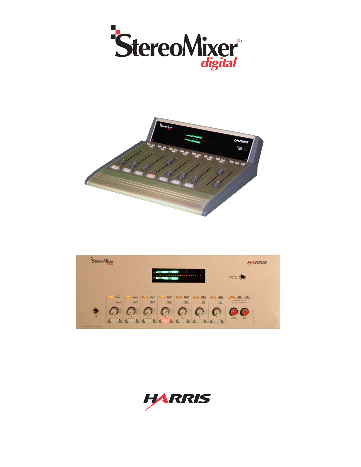
STEREOMIXER® DIGITAL OVERVIEW
StereoMixer®
in two models: rack-mount and desktop. SMX
for single talent/board operator use in applications such as
voice tracking studios, production rooms, nonlinear editing
suites and newsrooms. It has the following features:
• Four analog inputs (one input is mono), with a front panel
TRS stereo jack for convenient field recorder connection
• Three AES-3 digital inputs (S/PDIF-compatible) with
integral sample rate converters on each input
• Two Program buses and one mix-minus bus with both
analog and digital outputs
• Stereo bargraph meter display of the two program buses,
an External Monitor Input, or Cue
• Analog room monitor output, external talk input, talk
output, headphone amplifier output for talent headphones
• Room monitor mute logic plus opto-isolated interface
logic for a hot mic warning interface, intercom talk, mic
remote panel control, channel start command outputs
and timer reset output
• Audio and logic signals use separate connectors with AMP
MOD IV crimp terminal connectors (as used on the
BMX
Input Features
The mixer has seven inputs/channels. Four are analog, three
are digital. Rear panel switches set each analog input to either
-10 dBv (unbalanced) or +4 dBu (balanced) operation.
Channel 1 is a mono line-level input designed for a preamplified talent mic. It can alternately be set as a mono line
input. Channels 2, 3 and 4 are analog stereo line-level inputs.
Channels 2 and 3 can alternately be set as two additional mic
inputs from guest microphone preamps. Internal DIPswitches
digital
digital
(SMXd) is a compact mixer available
d
and RMX
digital
consoles) or D-sub (logic only)
was designed
(identified on page 9) set whether ch. 1, 2 and/or 3 are mic
inputs (which mute the monitor output) or line inputs.
Channel 4 is an analog stereo line-level input that features
a front panel TRS jack to allow easy plug-in of a field recorder
or DJ system (which is summed with a rear panel connector).
Channels 5, 6 and 7 are stereo AES-3 digital inputs with
integral sample rate conversion that accepts sample rates from
32 to 48 kHz.
Any one channel can be set as a Telco input from a phone
hybrid, ISDN or other 2-way communications device. The Telco
channel, set by internal DIPswitches (defined in Table 1 on
page 9), is always removed from the mix-minus output that is
returned to the Telco device.
Each of the seven input channels has these controls:
• Single channel On/Off button (lit by LEDs when On)
• Digital level control (linear faders on the desktop
version; rotary faders on the rack version)
• Function button (Talk on ch. 1, Cue on ch. 2 - 7)
• Program 1 and Program 2 bus assignment buttons
Output Features
The six analog outputs (+4 dBu balanced, -2 dBv unbalanced) are PGM 1, PGM 2, Room Monitor, Mix-Minus with
talk and Talk to External. The three digital outputs (PGM 1,
PGM 2, Mix-Minus) use a sample rate of 48 kHz (AES-3). An
amplified talent headphone output (1/4" TRS jack) has the
same monitor source as the Room Monitor output.
The Mix-Minus output is a sum of all the channels (postfader, post-switch) assigned to the same bus as the Telco channel—but minus the Telco channel audio. The mix-minus bus
is identified by the winking Telco bus assignment button. On
the left digital output and the analog output, talkback is added.
The digital right channel is a mix-minus without talk output.
Talkback audio is only active when channel 1 is set as a mic
input. Pressing the Talk button routes the mic—pre-switch
and pre-fader, to both the Talk output and to the Mix-Minus
with talk outputs.
Monitor Features
The monitor section has these controls:
• Monitor/meter source selectors (PGM 1, PGM 2, EXT)
• Digital level controls for the room monitor and talent
headphone outputs (linear faders on the desktop version;
rotary faders on the rack version)
The monitor outputs/meter can have four sources: Program
1, Program 2, an analog External Monitor input or Cue.
The Room Monitor and Headphones faders control the linelevel output for a pair of powered room monitor speakers and
2
HARRIS CORPORATION
Revision C • 12/05
the output level of the built-in headphone amplifier. The room
monitor output is automatically muted whenever a Mic channel is On (typically channel 1 is set as a mic, but channels 2
and 3 can also be set as mics). The talent/board operator head-
phone jack is next to the Channel 1 controls on the rack version. It is inset into the left side panel on the desktop version.
Power Supply
A separate “line lump” switching power supply, with three
regulated output voltages, is supplied with both versions of
SMX
d
. The ±15 volt outputs power the analog circuitry, while
a +5 volt output powers the DSP and logic control circuits.
Logic
The 2-way talk interface has External Talk audio and logic
inputs, a Talent/board operator Mic Talk output and Talk Out
Tally. These allow the SMX
ing intercom system, or to function as its own talkback system by adding an external audio switching relay.
There are three logic connectors on the rear panel:
• 12-pin AMP MOD IV: Logic outputs for a warning
lamp interface, talk tally output and an external talk
logic input.
• 14-pin AMP MOD IV: Logic inputs and outputs for
an optional cabinet-mount Mic Remote Panel
(PRE99-1197 or PRE99-1198) for channel 1 control from a remote talent mic location.
• 15-pin female D-Sub: Ch. 2 - 7 start pulse outputs
and a timer reset command closure.
d
to easily interface with any exist-
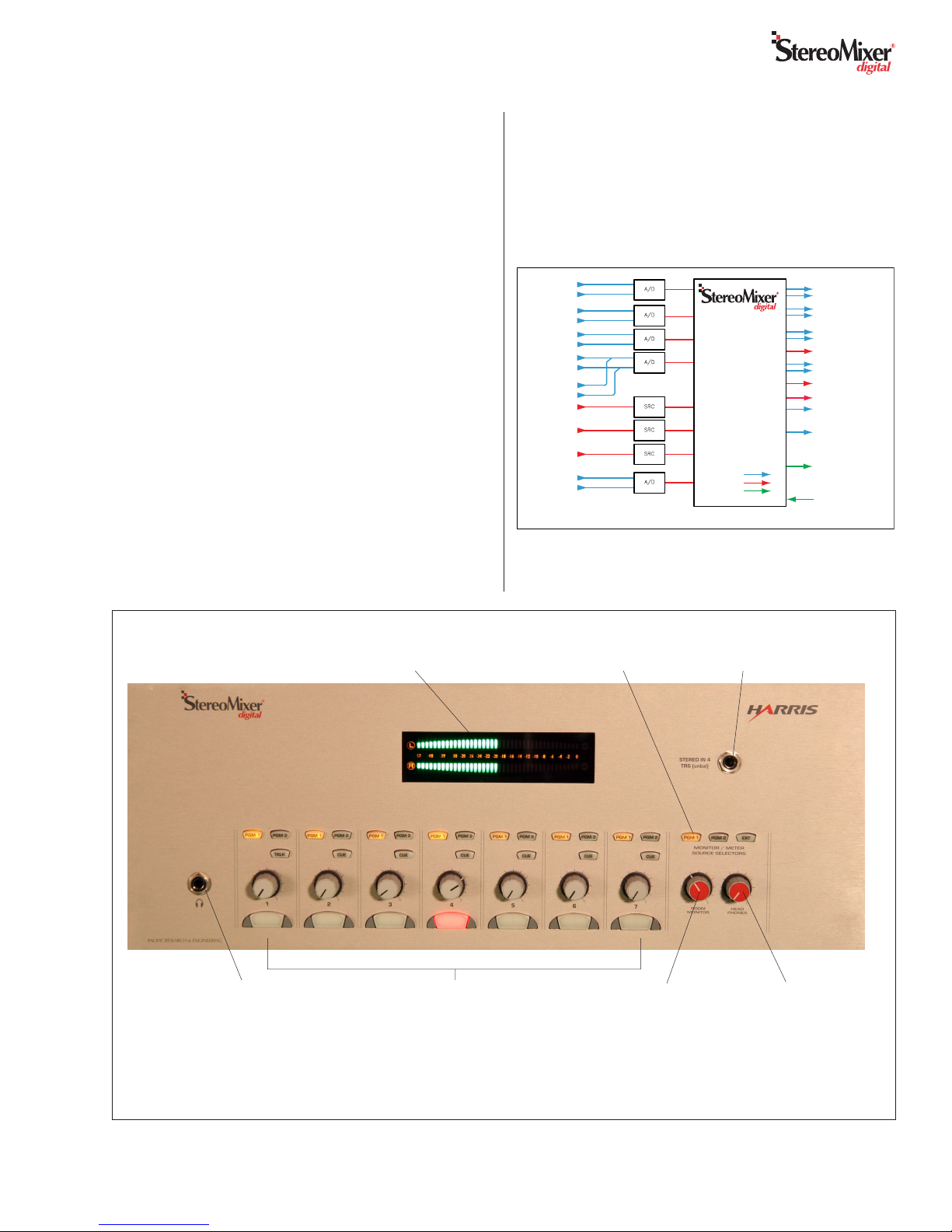
Stereo Bargraph Meter
(Displays average or
Average plus Peak)
MONO IN 1 *
EXT. TALK
ANALOG IN 2L *
ANALOG IN 2R *
ANALOG IN 3L *
ANALOG IN 3R *
ANALOG IN 4L
ANALOG IN 4R
AUX IN 4 STEREO
(Front Panel 1/4" TRS)
DIGITAL IN 5
DIGITAL IN 6
DIGITAL IN 7
EXT MONITOR IN L
EXT MONITOR IN R
* DIPSWITCH SET FOR MIC OR LINE FUNCTIONALITY
SRC: SAMPLE RATE CONVERSION
A/D: ANALOG TO DIGITAL CONVERSION
SMXd Block Diagram
Me ter, Monitor,
& Headphone
Source Selection
Audio Routing
& Mixing DSP
Digital to Analog
Converters
Logic I/O
Stereo Bargraph Meter
ANALOG AUDIO
DIGITAL AUDIO
LOGIC
TRS Stereo Input
(alternate source
for Channel 4)
HEADPHONE AMP OUT L
HEADPHONE AMP OUT R
ROOM MONITOR OUT L
ROOM MONITOR OUT R
PROGRAM 1 OUT L (ANALOG)
PROGRAM 1 OUT R (ANALOG
PROGRAM 1 OUT (DIGITAL)
PROGRAM 2 OUT L (ANALOG)
PROGRAM 2 OUT R (ANALOG
PROGRAM 2 OUT (DIGITAL)
MIX MINUS OUT (DIGITAL)
MIX MINUS OUT (ANALOG)
TALKBACK OUT (ANALOG)
EXT. TALLY LOGIC
(C/R Warning, Talk Tally,
Mic Panel Tallies, Start
Pulses, Timer Reset)
EXT. INPUT LOGIC
(Ext. Talk logic input,
Mic Panel Switches)
Tal e nt
Headphones
Jack
Channel controls (x7) with Bus
assign and Cue or Talk buttons, level
control & removable On/Off button lens
Room Monitor
Output level
control
Overview of the Rack Mount model’s
Controls and Features
(Desktop model’s controls are shown on the next page)
3
HARRIS CORPORATION
Revision C • 12/05
Tal e nt
Headphones
level control
 Loading...