

Harris 99-1300-0, 99-1300-1, 99-1300-2 Operation & Technical Manual

Broadcast
Console
99-1300-0 (14-input mainframe)
99-1300-1 (22-input mainframe)
99-1300-2 (30-input mainframe)
Operations
&
Technical
Manual
HARRIS 75-51
Revision B • 1/03
Broadcast Communications Division
www.broadcast.harris.com

HARRIS CORPORATION
ii
Revision B • 1/03

Contents
Safety Instructions ......................................... iv
Hazard/Warning Label Identification............. iv
Manual Revisions............................................ v
1- GENERAL INFORMATION
Product Overview ........................................1-1
Specifications ...............................................1-4
Warranty......................................................1-6
2- INSTALLATION
Console Installation......................................2-2
Mainframe Configuration ........................2-2
Connector Access ....................................2-3
Power Supply..........................................2-4
Grounding and Shielding ........................2-4
Installing Backup Batteries .....................2-4
Setting the Clock .....................................2-5
Event Timer ............................................2-6
Meter Setup ............................................2-6
Cabling and Wiring ......................................2-7
Required Cables and Wire.......................2-7
Wire Preparation ....................................2-7
Crimp T ool Operation ..............................2-8
Audio Connections .......................................2-9
Unbalanced Connections .......................2-10
Digital Clock Reference ..............................2-11
Logic Connections......................................2-11
Universal Input Logic Interface .............2-12
Setting DIP Switches.............................2-13
Quick Guides for Each Module...................2-16
Logic Connection Examples .......................2-50
Microphone Logic .................................2-50
Basic Peripheral Logic ..........................2-52
Complex Peripheral Logic.....................2-54
3- OPERATION
Module Overview .........................................3-1
Meter P anel Overview .................................. 3-1
Microphone Preamplifier Module .................3-2
Universal Input Module................................3-3
Telco/Codec Module.....................................3-5
Remote Line Selector (RLS) Module ..........3-10
Meter Switcher Module .............................. 3-11
Control Room Module................................ 3-12
Studio Module ...........................................3-13
Output 1 Module........................................3-14
Output 2 Module........................................3-14
Meter P anel................................................3-15
4- MAINTENANCE
Parts and Repair Services............................. 4-1
Parts Ordering and Repair Information...4-1
Spare and Replacement Parts..................4-2
Tool and Installation Kits........................4-3
Module Servicing .........................................4-3
F ader Servicing ....................................... 4-4
Clock and Event Timer................................. 4-5
Backup Batteries..........................................4-5
Power Supply...............................................4-5
General T roubleshooting T ips .......................4-6
5- ACCESSORIES
Furniture and Cabinetry...............................5-1
Furniture-Mounted Panels............................5-1
Peripheral Panels .........................................5-2
Mic Remote P anels.......................................5-2
Headphone Distribution Amp ......................5-2
Logic Wiring Diagrams & Cables..................5-2
INDEX
iii
HARRIS CORPORATION
Revision B • 1/03
Safety Instructions
1. Read All Instructions. Read all safety and operating
instructions before operating the product.
2. Retain All Instructions. Retain all safety and operating
instructions for future reference.
3. Heed All Warnings. You mu s t adher e to all warnings
on the product and those listed in the operating
instructions.
4. Follow All Instructions. Follow all operating and
product usage instructions.
5. He at . This produ ct must be situated away from any
heat sources such as radiators, heat registers, stoves,
or other products (including power amplifiers) that
produce heat.
6. Ven ti l ati on . Slots and openings in the product are
provided for ventilation. They ensure reliable operation
of the product and keep it from overheating. Do not
block or cover these openings during operation. Do
not place this product into a rack unless proper
ventilation is provided and the manufacturer’s
recommended installation procedures are followed.
7. Wate r a nd Mo i s t ur e. Do not use this product near
water such as a bathtub, wash bowl, kitchen sink, or
laundry tub, in a wet basement, or near a swimming
pool or the like.
8. At tach ment s. Do not use any attachments not
recommended by the product manufacturer as they
may cause hazards.
9. Power Sources. You must operate this product using
the type of power source indicated on the marking
label and in the installation instructions. If you are not
sure of the type of power supplied to your facility,
consult your local power company.
10. Grounding and Pol arization. This product is
equipped with a polarized AC plug with integral safety
ground pin. Do not defeat the safety ground in any
manner.
11. Power Cord Protection. Power supply cords must be
routed so that they are not likely to be walked on nor
pinched by items placed upon or against them. Pay
particular attention to the cords at AC wall plugs and
convenience receptacles, and at the point where the
cord plugs into the product.
12. Lig htni ng. For added protection for this product,
unplug it from the AC wall outlet during a lightning
storm or when it is left unattended and unused for
long periods of time. This will prevent damage to the
product due to lightning and power line surges.
13. Ov erl oad ing. Do not overload AC wall outlets,
extension cords, or inte gral convenience outlets as this
can result in a fire or electric shock hazard.
14. Obje ct a n d L i q u i d E nt ry. Never push objects of any
kind into this product through openings as they may
touch dangerous voltage points or short out parts,
which could result in a fire or electric shock. Never spill
liquid of any kind on the product.
15. Accessories. Do not place this product on an unstable
cart, stand, tripod, bracket, or table. The prod uct may
fall, causing serious injury to a child or adult and serious
damage to the product. Any mounting of the product
must follow manufacturer’s installation instructions.
16. Produ ct and Ca rt Co mbinat ion. Move this product
with care. Quick s tops, e xcessive force, and uneven
surfaces may cause the product and the cart
combination to overturn.
17. Se rvi ci ng. Refer all servicing to qualified ser vicing
personnel.
18. Dama ge Req ui rin g S e rvi ce. Unplug this product
from the wall AC outlet and refer servicing to qualified
service personnel under the following conditions:
a. When the AC cord or plug is damaged.
b. If liquid has been spilled or objects have fallen into
the product.
c. If the product has been exposed to rain or water.
d. If the product does not operate normally (following
operating instructions).
e. If the product has b een dropped or damaged in
any way.
f. When the product exhibits a distinct change in
performance. This indic ates a need for se r vice.
19. Replacement Pa rts. When replacement parts are
required, be sure the ser vice technician has used
replacement parts specified by the manufacturer or
that have the same characteristics as the original parts.
Unauthorized substitutions may result in fire, electr ic
shock, or other hazards.
20. Safety Check. Upon completion of an y repairs to this
product, ask the servic e technician to perform safety
checks to determine that the product is in proper
operating condition.
21. Clea n ing. Do not use liquid or aerosol cleaners. Use
only a damp cloth for cleaning.
Hazard/Warning Label Identification
The Exclamation Point symbol,
CAUTION
RISK OF ELECTRIC SHOCK
DO NOT OPEN
WARNING: SHOCK HAZARD - DO NOT OPEN
AVIS: RISQUE DE CHOC ELECTRIQUE - NE PAS OUVRIR
CAUTION: TO REDUCE THE RISK OF ELECTRIC SHOCK DO NOT
REMOVE ANY COVER OR PANEL. NO USER SERVICEABLE PARTS
INSIDE. REFER SERVICING TO QUALIFIED SERVICE PERSONNEL.
WARNING: TO REDUCE THE RISK OF FIRE OR ELECTRIC SHOCK,
DO NOT EXPOSE THE POWER SUPPLY OR CONSOLE TO RAIN OR
MOISTURE.
WARNING—This equipment generates, uses, and can radiate radio frequency energy. If not installed and used in accordance with the instructions in this
manual it may cause interference to radio communications. It has been tested and found to comply with the limits for a Class A computing device
(pursuant to Subpart J of Part 15 FCC Rules), which are designed to pro vide reasonable protection against such interfer ence when oper ated in a commercial environment. Operation of this equipment in a residential area is likely to cause interference, in which case the user, at his own expense, will be
required to take whatever measures may be required to correct the interference.
iv
HARRIS CORPORATION
within an equilateral triangle, alerts the
user to the presence of important
operating and maintenance (servicing)
instructions in product literature and
instruction manuals.
The Lightning Flash With
Arrowhead symbol, within an
equilateral triangle, aler ts the user to
the presence of uninsulated
dangerous voltage within the
product’s enclosure that may be of
sufficient magnitude to constitute a
risk of electric shock.
Revision B • 1/03

Manual Revisions
This page provides a quick reference of the
current document pages and their revision level. If
you receive a revision to this document from Harris,
replace the old manual pages with the new ones and
discard the old pages. Replace this page with the new
Manual Revisions page.
Revision Affected pages Comments
A All pages 2/02 First Release
B All pages 1/03 corrected various
installation & operation
descriptions. Added
accessory product
information.Condensed
manual page count.
v
HARRIS CORPORATION
Revision B • 1/03

HARRIS CORPORATION
vi
Revision B • 1/03

General
Information
Thank you for joining the growing ranks of
broadcasters employing Harris Corporation prod-
ucts designed by Pacific Research & Engineering.
Harris Corporation supplies audio products and sys-
tems to the world’s leading broadcast facilities. Our
mission is to provide the finest quality products,
systems, documentation, and after -sale support. We
invite comments and suggestions for improvements
to this documentation and to all of our services.
The Legacy is a very sophisticated console with
an extensive range of features contained in a compact design. To obtain maximum benefit from the
console’s capabilities, read the
Operation
PRODUCT OVERVIEW
Each Legacy console ships with the following
modules installed in the mainframe:
chapters prior to product installation.
• Microphone Preamplifier module (one
5-input Mic Preamp PCA standard, second
5-input Mic Preamp PCA optional)
• Universal Input modules (as ordered)
• Telco/Codec modules (up to 4, as ordered)
• Remote Line Selector (RLS) modules
(as ordered)
Installation
and
1
• Meter Switcher module (1 standard)
• Control Room module (1 standard)
• Studio module (1 optional)
• Output modules (2 standard)
Blank panels cover unused module positions.
The Legacy’ s motherboard and module area is
completely contained within a sheet metal and
extruded aluminum chassis for strength and RFI
immunity. The meter panel is hinged at the rear,
closing over the upper part of the modules to cover
the audio and logic connectors and the Logic Setup
switches. The chassis bottom is open beneath the
meter panel for easy cable access.
Module Descriptions
Microphone Preamplifier Module
This module (PRE99-1151-2) can hold ten
high-performance preamplifiers (five are standard
with an additional five optional). Each has a gain
trim control under a security cover. Phantom
power (+48 VDC) is selectable for each input. Each
Mic Preamp boosts its mic-level inputs (from -65
dBu to -30 dBu) to a line level (+4 dBu), low-impedance, balanced output for connection directly
to a Universal Input module or to outboard mic
processing equipment.
One module with a 5-input Mic Preamp PCA is
standard; a second optional 5-input PC A may be
installed. An additional 5-input Mic Preamplifier
module (PRE99-1151-2) or a 10-input Mic
Preamplifier module (PRE99-1151-1) may be installed into the slot directly to the right of the standard Mic Preamplifier module.
1-1
HARRIS CORPORATION
Revision B • 1/03

1 General Information
Universal Analog/Digital Input Module
The Universal Input modules (PRE99-1315)
feature two inputs (A and B), each of which can
accept analog or digital signals. Setup switches on
the module set the source for each input. They
also set the source level (for analog signals) or the
attenuation amount (for digital signals). Each input has its own fully independent parallel logic
control connector for remote control of the module and/or module control of the associated source
equipment.
Each Universal Input module includes the following controls or features: A/B input selection,
channel on/off control, fader level control, cue
control, mode selection with pan/balance control,
Send control, and output bus selection to four program buses and one off-line bus.
Two 24-pin logic connectors connect logic wiring to/from external control panels or peripherals. DIP switches set logic and module function
options for the A and B inputs.
Telco/Codec Input Module
Up to four Telco/Codec (Telco) modules can be
installed into any of the input module slots on the
mainframe. The optional Telco module (PRE99-
1316) has a single audio input (analog or digital)
from a remote send and receive device (like a telephone hybrid, satellite transceiver , ISDN interface,
or other stereo or mono Codec).
Each module features manual or automatic control of the F oldback signal returned to the h ybrid
or codec. T he F oldback signal for each Telco module can be manually set to an y program or off-line
bus. T he F oldback signal can also follow the T elco
module’s on/off status when the Auto-Foldback
function is active. The Auto-Foldback function
automatically switches the feed to the caller between the off-line mix and the assigned bus with
the highest priority. For more information, see the
Telco Operation section on pages 3-7 to 3-9.
Each Telco module includes the following controls or features: channel on/off control, fader level
control, cue control, mode selection with pan/balance control, Send control, record and monitor
controls, and output/Foldback selection to four
program buses and one off-line bus. Logic I/O is
available for logic wiring to/from the hybrid or
codec.
Remote Line Selector (RLS) Module
This module (PRE99-1323) features two banks
of eight selection buttons to independently route
the eight input signals to the two outputs. The
module switch either analog or digital signals, as
set by a DIP switch on the module.
Meter Switcher Module
This module (PRE99-1317) is located to the
right of the input module area. It provides control
of the digital timer and contains the meter source
selector buttons and the signal drivers for all the
meter displays.
The timer control section features stop, start,
hold, and reset controls, as well as whether the
modules automatically reset the timer .
Control Room Module
This module (PRE99-1318) contains the monitor source selection and control facilities for the
console operator , and a co-host and a guest in the
control room. The module has parallel logic control (via a 14-pin connector) which provides external monitor dimming or muting, and warning
light control. The module includes four external
monitor inputs and six monitor and headphone
outputs. The outputs can simultaneously monitor
any combination of up to six analog sources (four
external inputs and Telco Record and Monitor)
and two digital sources (four programs and Send).
The Control Room module features monitor and
headphone fader -level controls, monitor -mode con-
HARRIS CORPORATION
1-2
Revision B • 1/03

1 General Information
trol, cue and talkback level controls, and headphone Auto-Cue select.
Studio Module
The optional Studio module (PRE99-1319) is
installed to the right of the Control Room module.
It provides a monitor and talkback-level control
for one studio or voice booth. The monitor source
can be any combination of 11 sources (four exter nal inputs, four programs, Send, and T elco Record
and Monitor) simultaneously.
The Studio module has a 14-pin parallel logic
connector for external dimming or muting of the
studio monitor speakers and control of a studio
warning light interface. Controls also provide the
ability to talk to or from a studio and an external
location.
Output Modules
Two Output modules ship standard with the
Legacy.
The Output 1 module (PRE99-1320) contains
the digital-to-analog converters and mix matrices
for creating mix-minus foldbacks to support up
to four Telco/Codec modules. It also contains individually mixed outputs for Telco/Codec recording. There is a mix-minus output for each Telco/
Codec module. Digital and analog outputs are provided for the mix-minus and recorder feed outputs. For digital outputs, sample rates of 48 kHz
and 44.1 kHz are supported. T he mix-minus analog outputs are fixed at +4 dBu. This module features output sample rate selectors for digital outputs and a gain trim control for the analog Telco
record mix output.
The Output 2 module (PRE99-1321) contains
the AES digital output drivers, digital-to-analog
converters, and analog line amplifiers for the Send
output and the four program outputs. The digital
output sample rate is 48 kHz. An output sample
rate of 44.1 kHz can be selected for the program
1 and 2 auxiliary outputs, the program 3 and 4
outputs, and the Send output. Gain trim controls
for the analog outputs are also provided.
Pow er Supply
The separately packaged rack-mount power
supply assembly (PRE99-1202) uses keyed connectors to supply a single +48 volts DC to the console mainframe. There are two connectors from
the power supply assembly to the console: one connector supplies DC power and the other supplies
electrical signal information to the console. The
power supply module has an on/off switch and
an LED indicator on the front panel. The power
supply is fully regulated and protected against excessive current by internal fuses and electronic
safeguards.
1-3
HARRIS CORPORATION
Revision B • 1/03

1 General Information
SPECIFICATIONS
The specifications for the Legacy are significantly more complete, and the related test conditions are more defined, than those usually shown
for consoles in this class. Be sure to follow the test
conditions and measure in the units as stated.
The specifications are for a fully loaded Legacy30 input mainframe.
Test Conditions:
Specifications are for the basic signal paths, per
channel, with >1k ohm loads connected to the
analog main outputs.
0 dBu corresponds to an amplitude of 0.775
volts RMS regardless of the circuit impedance. This
is equivalent to 0 dBm measured into a 600 ohm
circuit for convenient level measurement with
meters calibrated for 600 ohm circuits. Noise specifications are based upon a 22 kHz measurement
bandwidth. T he use of a meter with 30 kHz bandwidth will result in a noise measurement increase
of approximately 1.7 dB.
Total Harmonic Distortion (THD+N) is measured at a +18 dBu output level using 1 kHz or a
swept signal with a 22 kHz low-pass filter.
FSD = Full Scale Digital, +24 dBu
Microphone Preamplifiers
Source Impedance: 150 ohms
Input Impedance: 5 k ohms minimum, balanced
Input Level Range: Adjustable, -65 to -30 dBu
Input Headroom: >20 dB above nominal input
Output Level: +4 dBu, nominal
Analog Line Inputs
Input Impedance: >40 k ohms, balanced
Input Level Range: Selectable; -10 dBv, +4 dBu,
+6 dBu, +8 dBu
Input Headroom: 20 dB above nominal input
Analog Main Outputs
Output Source Impedance: <3 ohms balanced
Output Load Impedance: 1 k ohms minimum
Nominal Output Levels: Program, Send, Telco/Codec
Mix-Minus, T elco Record Mix F eed: +4 dBu, adjustable between +3 dBu and +9 dBu
Maximum Output Levels: Program, Send, Telco/
Codec Mix-Minus, Telco Record Mix Feed:
+24 dBu; +28 dBu with 100k output load impedance and nominal output level adjusted to
+8 dBu
Digital Inputs and Outputs
Reference Level: +4 dBu (-20 dB FSD)
Digital I/O: Through digital input and digital Pro-
gram, Send, Telco/Codec Mix-Minus outputs
Signal Format: AES-3, S/PDIF (input only)
AES-3 Input Compliance:
24-bit sample rate conver-
sion available, individually s witch selectable
AES-3 Output Compliance:
Digital Reference:
24-bit
Crystal (internal) or AES-3 (ex-
ternal) at 48 kHz ±100 ppm
Internal Sample Rate:
48 kHz
Output Sample Rates: Program 1 and 2 Main out-
puts 48 kHz; Program 1 and 2 Aux, Program 3
and 4, Send, T elco/Codec Mix-Minus, and Telco
Record Mix outputs 48 kHz or 44.1 kHz, individually switch selectable
Processing Resolution:
24-bit fixed with extended
precision accumulators
Conversions:
A/D 24-bit, Delta-Sigma, 128x
oversampling on all digital inputs; D/A 24-bit,
Delta-Sigma, 128x ov ersampling
Latency:
<1.6 ms, mic in to monitor out
HARRIS CORPORATION
1-4
Revision B • 1/03

1 General Information
Monitor Outputs
Output Source Impedance: <3 ohms, balanced
Output Load Impedance: 1 k ohms minimum
Output Level: +4 dBu nominal, +24 dBu maximum
Frequency Response
Microphone or Line Input to Program or Send Output:
+0 dB/-0.5 dB, 20 Hz to 20 kHz
Dynamic Range
Analog Input to Analog Output: 105 dB referenced to
FSD, 108 dB “A” weighted to FSD
Analog Input to Digital Output: 109 dB referenced to
FSD
Digital Input to Analog Output: 107 dB referenced to
FSD, 110 dB “A” weighted to FSD
Digital Input to Digital Output: 138 dB
Equivalent Input Noise
Microphone Preamp: -127 dBu, 150 ohm source
Crosstalk Isolation
Program-to-Program or to-Program or to-Send: >95 dB,
20 Hz to 20 kHz
A Input to B Input, B Input to A Input:
>110 dB, 20 Hz
to 20 kHz
Stereo Separation
Analog Program Outputs: >86 dB, 20 Hz to 20 kHz
Console Power Requirements
Fully configured Legacy-14: 185 watts at 115/230
VAC, ±12%, 50/60 Hz
Fully configured Legacy-22: 250 watts at 115/230
VAC, ±12%, 50/60 Hz
Fully configured Legacy-30
:
285 watts at 115/230
VAC, ±12%, 50/60 Hz
Power Supply Voltage
Console power: +48 VDC at 8.34 Amp, redundant
operation optional
Total Harmonic Distortion + Noise
Mic Pre Input to Mic Pre Output: <0.005%, 20 Hz to
20 kHz, -38 dBu input, +18 dBu output, 100k
ohm load, 22 kHz filter bandwidth
Analog Input to Analog Output: <0.003% at 1 kHz,
+18 dBu input, +18 dBu output, 100 k ohm
load, 22 kHz filter bandwidth
Digital Input to Digital Output:
<0.00016%, 20 Hz to
20 kHz, -20 db FSD input, -20 db FSD output,
20 kHz filter bandwidth
Digital Input to Analog Output:
<0.003% at 1 kHz,
-6 db FSD input, +18 dBu output, 100 k ohm
load, 22 kHz filter bandwidth
Power Supply Ground
Rack-mount power supply frame: grounded through
AC cord
Power Supply Connection
AC input: IEC power cord
DC output: two keyed multi-pin connectors
Dimensions
Legacy-14: 9.75"
Legacy-22: 9.75
Legacy-30: 9.75
x 41.13" x 33.38" (H, W, D)
"
x 54.44" x 33.38" (H, W, D)
"
x 67.24" x 33.38" (H, W, D)
Power Supply (Rack-mount power supply frame):
3.5
"
(2 RU) x 19.0" x 16.0"
(H, W , D)
Harris Corporation reserves the right to change
specifications without notice or obligation.
1-5
HARRIS CORPORATION
Revision B • 1/03

1 General Information
WARRANTY
The Legacy digital console carries a
manufacturer’s warranty which is subject to the
following guidelines and limitations:
A) Except as expressly excluded herein, Harris
Corporation (“Seller”) warrants equipment of
its own manufacture against faulty workmanship or the use of defective materials for a period of one (1) year from date of shipment to
Buyer . The liability of the Seller under this W arranty is limited to replacing, repairing, or issuing credit (at the Seller’s discretion) for any
equipment, provided that Seller is promptly
notified in writing within five (5) days upon
discovery of such defects by Buyer , and Seller’ s
examination of such equipment shall disclose
to its satisfaction that such defects existed at
the time shipment was originally made by
Seller, and Buyer returns the defective equipment to Seller’s place of business in Mason,
Ohio, packaging and transportation prepaid,
with return packaging and transport guaranteed.
E) This Warranty is void for equipment which
has been subject to abuse, improper installation, improper operation, improper or omitted maintenance, alteration, accident, negligence (in use, storage, transportation, or handling), operation not in accordance with
Seller’s operation and service instructions, or
operation outside of the environmental conditions specified by Seller.
F) This Warranty is the only warranty made by
Seller, and is in lieu of all other warranties,
including merchantability and fitness for a particular purpose, whether expressed or implied,
except as to title and to the expressed specifications contained in this manual. Seller ’ s sole
liability for any equipment failure or any
breach of this Warranty is as set forth in subparagraph A) above; Seller shall not be liable
or responsible for any business loss or interruption, or other consequential damages of an y
nature whatsoever, resulting from any equipment failure or breach of this warranty.
B) Equipment furnished by Seller, but manufac-
tured by another, shall be warranted only to
the extent provided by the other manufacturer .
C) Thermal filament devices, such as fuses, are
expressly excluded from this warranty.
D) The warranty period on equipment or parts
repaired or replaced under warranty shall expire upon the expiration date of the original
warranty .
HARRIS CORPORATION
1-6
Revision B • 1/03
Installation
"
8
8
8
8
8
8
8
8
8
8
8
8
8
8
8
8
8
8
8
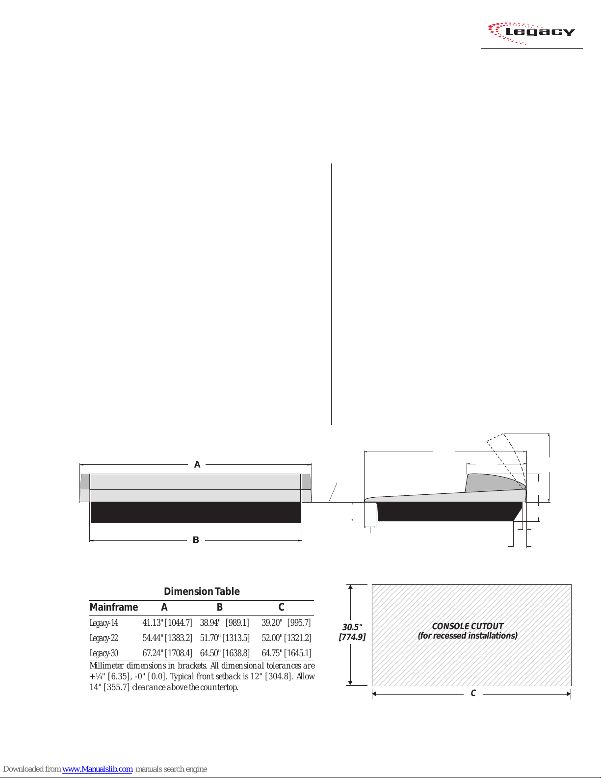
The Legacy mainframe is designed to
“drop into” a cutout (shown below) in the studio
furniture countertop. A minimum of 14 inches
(355.7 mm) of vertical clearance above the
countertop is required to fully open the meter
panel. T he rear 2.5 inches (63.5 mm) of the main-
2
The Legacy console shipment consists of:
• The 14-, 22-, or 30-input mainframe with the
standard modules (Microphone Preamp, Meter
Switcher , Control Room, and Outputs) installed,
along with the other modules ordered (Universal Input, T elco/Codec, RLS, Studio), and blank
panels to cover any unused positions.
• The rack-mount power supply assembly .
• T he Legacy Tool kit (3 AA batteries, AMP MOD
IV crimp tool and contact removal tool, hex
driver, and module removal tool).
frame is open so wiring can be easily dressed up
through the mainframe to the module connectors,
which are hidden below the meter panel.
Console Front View Console Side View, with dimensions (inches & [mm])
Dimension T able
Mainframe A B C
Legacy-14 41.13" [1044.7] 38.94" [989.1] 39.20" [995.7]
Legacy-22 54.44" [1383.2] 51.70" [1313.5] 52.00" [1321.2]
Legacy-30 67.24" [1708.4] 64.50" [1638.8] 64.75" [1645.1]
Millimeter dimensions in brackets. All dimensional tolerances are
+¼" [6.35], -0" [0.0]. Typical front setback is 12" [304.8]. Allow
14" [355.7] clearance above the countertop.
• Audio and Logic connector kit. The kit contains all the AMP MOD IV connector housings
and receptacle contacts typically needed for
installation.
COUNTERTOP
4.00"
[101.6]
2.48"
[63.0]
23456789012345678901234567890121234567
23456789012345678901234567890121234567
23456789012345678901234567890121234567
23456789012345678901234567890121234567
23456789012345678901234567890121234567
23456789012345678901234567890121234567
23456789012345678901234567890121234567
23456789012345678901234567890121234567
30.5"
[774.9]
23456789012345678901234567890121234567
23456789012345678901234567890121234567
23456789012345678901234567890121234567
23456789012345678901234567890121234567
23456789012345678901234567890121234567
23456789012345678901234567890121234567
23456789012345678901234567890121234567
23456789012345678901234567890121234567
23456789012345678901234567890121234567
23456789012345678901234567890121234567
23456789012345678901234567890121234567
2-1
HARRIS CORPORATION
Revision B • 1/03
33.38"
[847.9]
11.79"
[299.5]
CONSOLE CUTOUT
(for recessed installations)
C
5.75"
[146.1]
4.00"
[101.6]
0.75"
[19.1]
2.50"
[63.5]
14.00
[355.6]
2 Installation
Console Installation
To simplify console installation, logic cable wir ing diagrams for specific peripheral equipment are
available from the Harris Technical Services department. See page 4-1 for contact information.
INSTALLATION NOTE: Do not locate the con-
sole near intense electromagnetic hum fields, such
as those produced by large power transformers
and by audio amplifiers that use inexpensive
power transformers operating in or near saturation. Strong electromagnetic fields may impair the
performance of the Legacy and neighboring equipment. Audio cables must also be routed to achieve
maximum practical distance from all AC power
mains wiring.
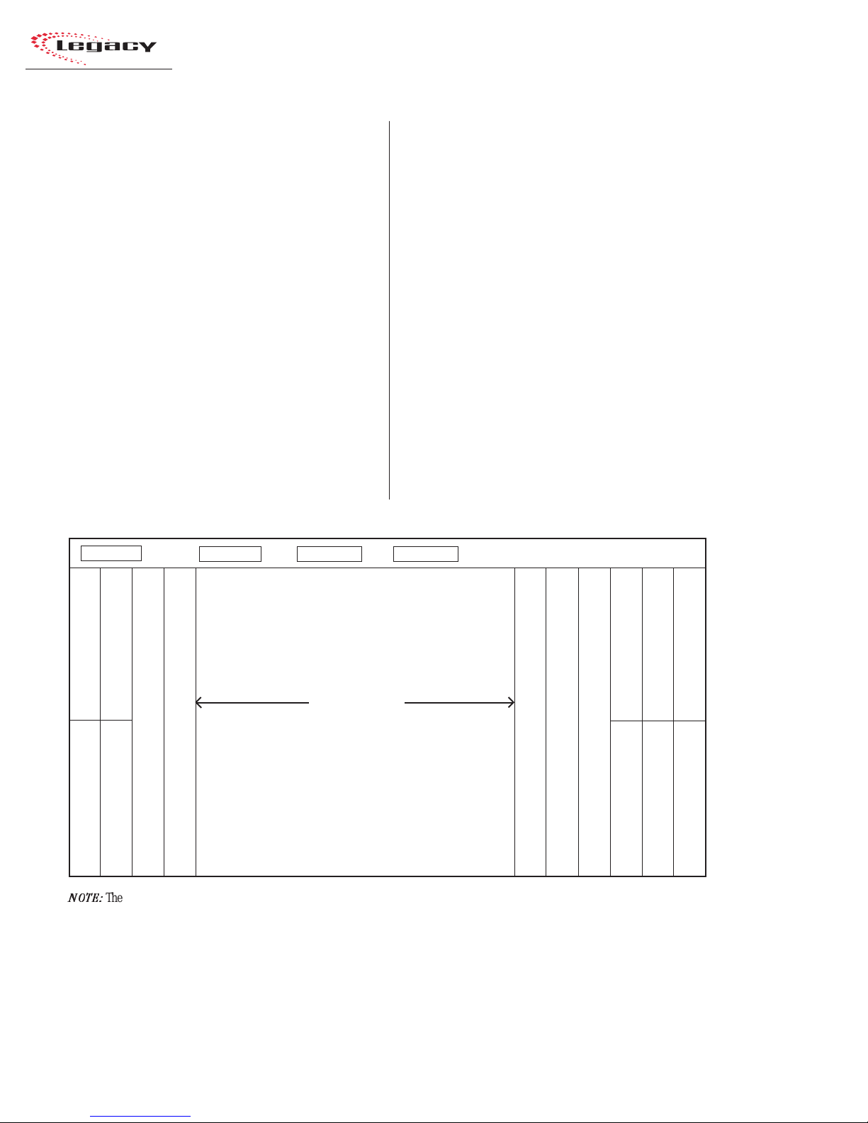
Legacy Mainframe, Module Configuration
MAINFRAME CONFIGURATION
The Legacy design positions the input modules
in the physical center of the mainframe. T his gives
the operator equal reach to peripheral equipment
located to the either side of the console.
Module Placement
The 14, 22, or 30 input module positions can
have any combination or order of the following
modules installed: Universal Input, Telco/Codec
(four maximum), and Remote Line Selector (RLS).
The remaining console positions are fixed. T he Mic
Preamplifier module(s), Meter Switcher module,
Control Room module, optional Studio module,
and the two Output modules must be positioned
as shown in the illustration below.
DSP Card 1 (Master) DSP Card 2 DSP Card 3* DSP Card 4*
Mic Preamp (standard)
Mic Preamp 2 (optional)
12.5” blank panel (standard)
Input modules
* (number of DSPs present
set by the frame size)
Output 1 (standard)
Output 2 (standard)
12.5” blank panel
The input module positions are
filled with any combination or
number of Universal Input and
Remote Line Selector modules, and
up to four Telco/Codec modules.
Control Room (standard)
Meter Switcher (standard)
Unused positions are covered with
25" Blank Panels.
Reserved position (covered by a 25" Blank panel)
Reserved position (covered by a 25" Blank panel)
12.25" Blank Panel (standard)
12.25" Blank Panel (standard)
NOTE:
The number of input module positions matches the console model number (e.g., Legacy-22 has 22 input positions). There are
two DSP cards in the Legacy-14, three in the Legacy-22, and four in the Legacy-30.
The areas covered by the five 12.25" Blank Panels can be used for mounting Harris BMXdigital Accessory Panels or custom remote
control panels. Since the Harris BMXdigital Accessory Panels are 6" long, a PRE99-1100 Divider Kit (for mounting up to four
Accessory Panels in place of two 12.25" Blank Panels), or a PRE99-1101 Divider Kit (for mounting up to six Accessory Panels in place
of three 12.25" Blank Panels) is required. Typically, the PRE99-1100 Divider Kit is installed in place of the Blank Panels on the left
end of the console and the PRE99-1101 is installed in place of the Blank Panels on the right end of the console. 6" Blank Panels
(PRE99-1714-3) cover unused Accessory Panel positions.
Studio (optional) 25” blank panel (standard)
12.25" Blank Panel (standard)
12.25" Blank Panel (standard)
12.25" Blank Panel (standard)
(standard)
HARRIS CORPORATION
2-2
Revision B • 1/03
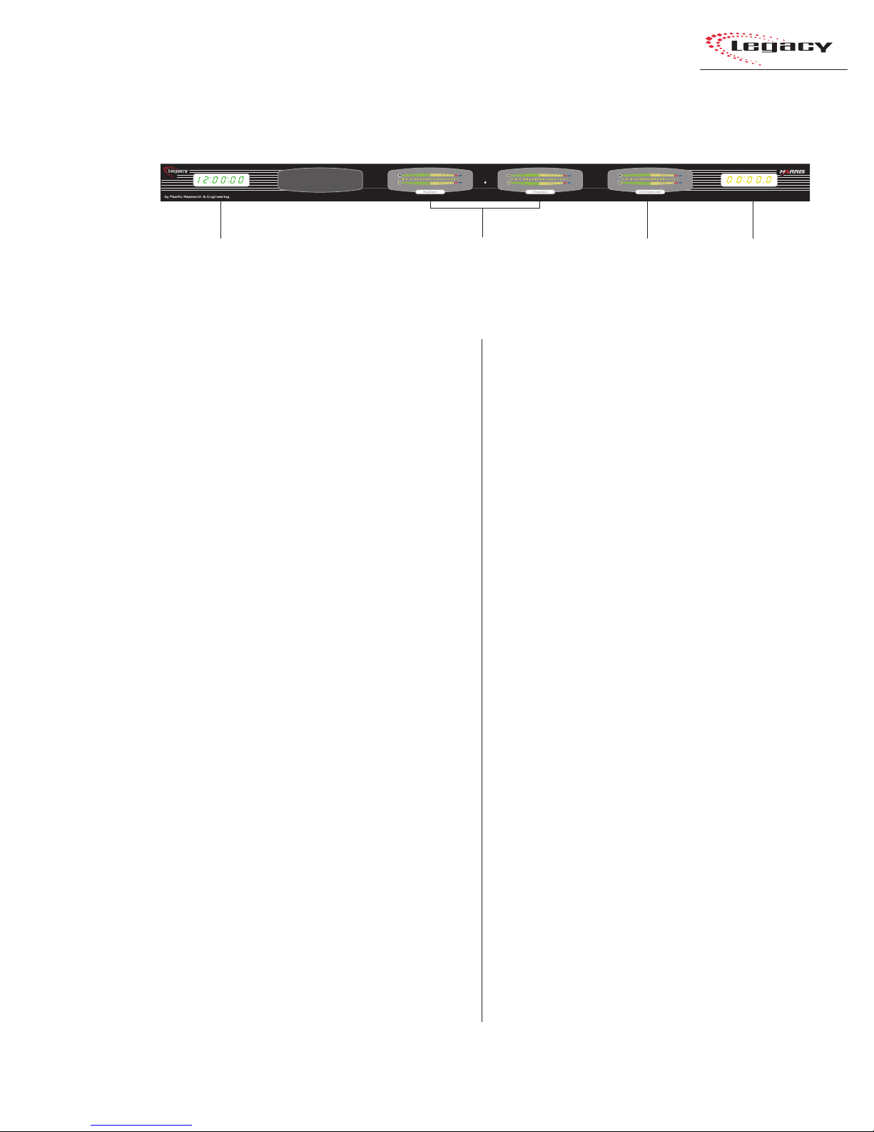
Legacy Meter Panel
2 Installation
Clock
Meter Panel
The meter panel contains three horizontal bargraph meters. T wo of the meters pro vide individual
level monitoring for the Program 1 and 2 outputs. The third meter is used to monitor the level
of Cue, Program 3 or 4, any external input, the
Send output, or the Telco Record output, as selected on the Meter Switcher module. The level at
which the peak indicator (PK) comes on, as well
as the meter display mode (peak hold or non-peak
hold), may be set for each meter via DIP s witches
on each meter display board.
The meter panel also contains a slaveable 12/
24-hour digital clock (HH:MM:SS) and an event
timer (MM:SS:T) that can be controlled manually , through buttons on the Meter Switcher module, or automatically through module On commands.
For additional information on the meter panel,
see pages 3-15 and 3-16.
Main Meters
(Program 1 and 2)
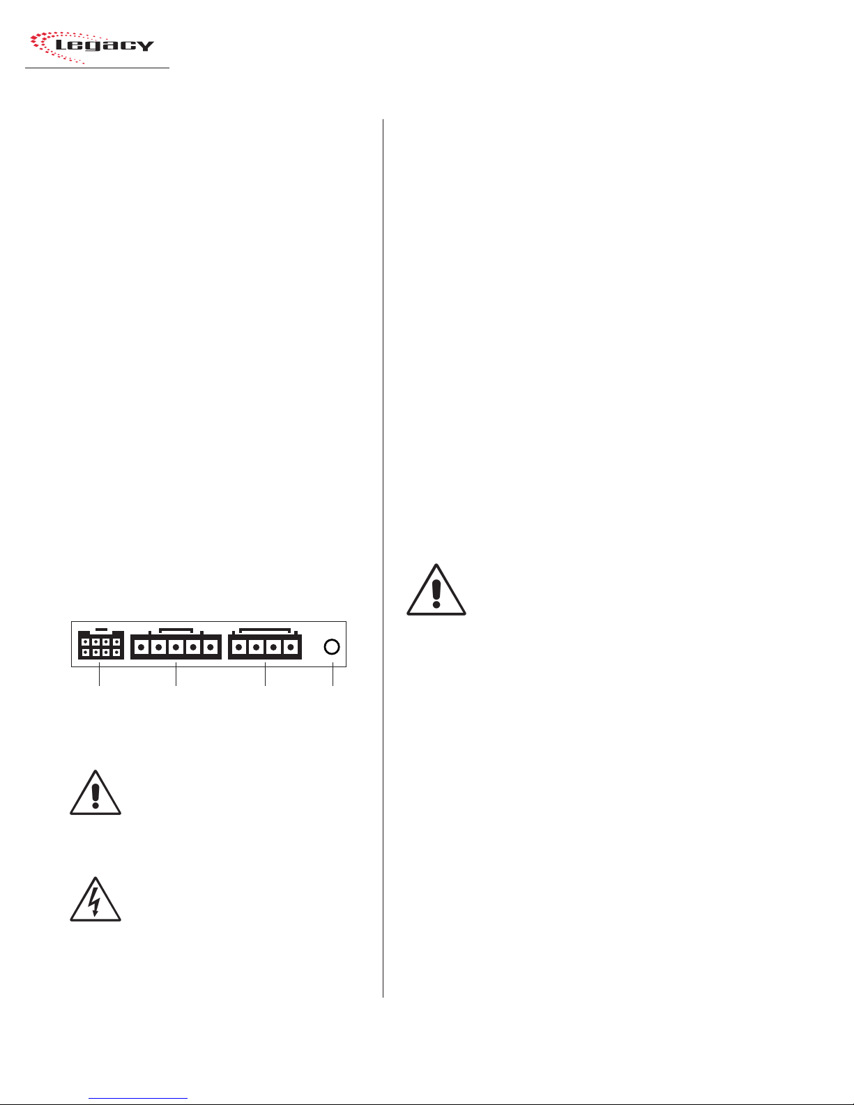
CONNECTOR AC CESS
meter panel in normal operation. T he meter panel
connects to the rear of the console by hinges. To
access the connectors, open the meter panel by
lifting it up and rotating it toward the rear of the
console until it stops.
the way so that it does not accidentally fall shut.
be removed from the mainframe chassis.
Aux M et e r
(Meter Switcher: Displays
Cue, Program 3 or 4, Send,
or Telco Record)
Event
Timer
All module connectors are hidden below the
Caution: Make sure that the panel is open all
To facilitate initial wiring, the meter panel can
To remove the meter panel from the mainframe:
1 Open the meter panel fully and unplug the
meter power cable (attached to the rear panel)
and the two cables (meter signals and talkback mic) from the Meter Switcher module.
2 With another person holding the meter panel,
remove the screws and bushings that attach
each gas spring to the meter panel. Lay the
gas springs on the mainframe while working.
3 Unlatch the hinges by moving the release pins
to their unlocked positions and lift the meter
panel up and off the mainframe.
To reinstall the meter panel, align the two halves
of the hinges, then release the pins out of their
unlocked positions.
Reattach each gas spring to the meter panel by
inserting a screw through the gas spring and the
bushing.
2-3
HARRIS CORPORATION
Revision B • 1/03
2 Installation
POWER SUPPLY
The power supply assembly is rack mounted (it
requires 2 RU or 3.5" [88.9 mm] of rack space)
within the console cabinetry , below and to the left
or right of the supporting countertop. The Legacy
Power Supply must be installed so that the 30
foot power supply cable supplied with the Power
Supply is not under any tension when routed
through the cabinet and connected to the
mainframe’s rear panel connectors.
Connecting the Power Supply
The power supply cable has two connectors:
• A 5-pin connector to supply 48 volt DC
power to the console.
• A 4-pin connector to supply power supply
status information (Imminent Power Loss)
to the console.
Both connectors must be attached to the back
of the Legacy and to the power supply.
Power Connections —
Console Mainframe, Rear Panel
GROUNDING AND SHIELDING
The broadcast facility’s technical ground can
be connected to the mainframe chassis using the
threaded insert on the rear of the console (shown
in the Power Connections drawing on this page).
Use a 10-32 screw and crimp lug to terminate the
facility’s technical ground wire.
Connect the cable shields at both the console
and the peripheral end when all system components share a common ground potential and are
using isolated ground AC outlets tied individually
back to the main technical ground.
If isolated ground AC outlets are not available,
connect the cable shields at the console end only.
The shields should be floated (left unconnected)
at the peripheral device end. Ensure the peripheral devices connect to a clean ground through
their power cords, or through separate ground
wires to the facility’s technical ground.
POWER SUPPLY GROUNDING
NOTE: The Power Supply chassis
connects to the AC mains safety or
“U” ground wire.
Meter
Panel
Power
48 VDC
Power
Power
Supply
Status
DC GROUNDING NOTE:
connect
the audio or logic supply
ground wiring to the chassis of the
power supply .
AC GROUNDING NOTE: Do not
defeat the safety ground in any way.
Doing so may provide a potentially
dangerous condition to the operator .
HARRIS CORPORATION
Threaded
Insert for
10-32
screw
Do not
AUDIO GROUND NOISES: Buzz pickup is gener-
ally electrostatic—such as capacitive coupling
between an audio line and a power line. To avoid
audio ground noises, do not route audio lines in
the same wireway as an AC power line.
INST ALLING BA CKUP BATTERIES
Three AA rechargeable NiCad batteries are supplied in the 76-2001 Tool Kit. They supply a “Keep
Alive” voltage to hold each module’s logic state
during momentary power outages. They mount in
a battery clip located below the three 12" blank
panels on the right end of the console.
To install the backup batteries:
1 Remove the three blank panels located in front
of the Output modules.
2-4
Revision B • 1/03
2 Installation
3
3
3
3
3
3
3
3
3
3
3
3
3
3
3
3
3
3
3
3
3
3
3
3
3
3
3
3
3
3
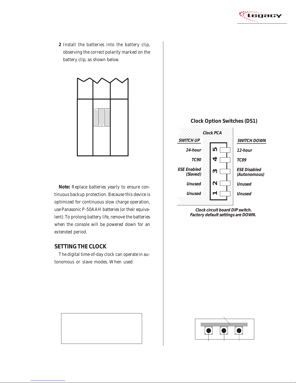
2 Install the batteries into the battery clip,
observing the correct polarity marked on the
battery clip, as shown below.
Backup Battery Installation
Output 1
+- +
-+-
12.25" Blank panel
Middle 12.25" Blank Panel
removed to show the
battery clip
Note: Replace batteries yearly to ensure con-
tinuous backup protection. Because this device is
optimized for continuous slow charge operation,
use Panasonic P-50AAH batteries (or their equiv alent). To prolong battery life, remo ve the batteries
when the console will be powered down for an
extended period.
SETTING THE CL OCK
The digital time-of-day clock can operate in autonomous or slave modes. When used autonomously (the factory preset), a temperature-controlled quartz crystal oscillator controls the clock
timing. In slav e mode, clock timing comes from a
TC89- or TC90-compatible ESE master clock reference signal.
Master clocks are available from:
ESE
142 Sierra St.
El Segundo, CA 90245.
Telephone: 310.322.2136
www.ese-web.com
Output 2
the type of ESE signal (TC89 or TC90), and the
type of clock time desired (12-hour or 24-hour
format) are set using DIP switch DS1 on the clock
PCA. DS1 is on the right rear edge of the circuit
board.
Blank
The clock PCA is mounted behind the clock display on the meter panel.
234567890123456789012
234567890123456789012
234567890123456789012
234567890123456789012
234567890123456789012
12.25" Blank panel
234567890123456789012
SWITCH UP
234567890123456789012
234567890123456789012
234567890123456789012
234567890123456789012
234567890123456789012
234567890123456789012
234567890123456789012
234567890123456789012
234567890123456789012
234567890123456789012
234567890123456789012
ESE Enabled
234567890123456789012
234567890123456789012
234567890123456789012
234567890123456789012
234567890123456789012
234567890123456789012
234567890123456789012
234567890123456789012
234567890123456789012
234567890123456789012
234567890123456789012
234567890123456789012
234567890123456789012
be set after power-up. There are three clock set
buttons on the bottom left front of the clock PCA.
2-5
HARRIS CORPORATION
Revision B • 1/03
The operating mode (autonomous or ESE slav e),
To access the clock PCA, open the meter panel.
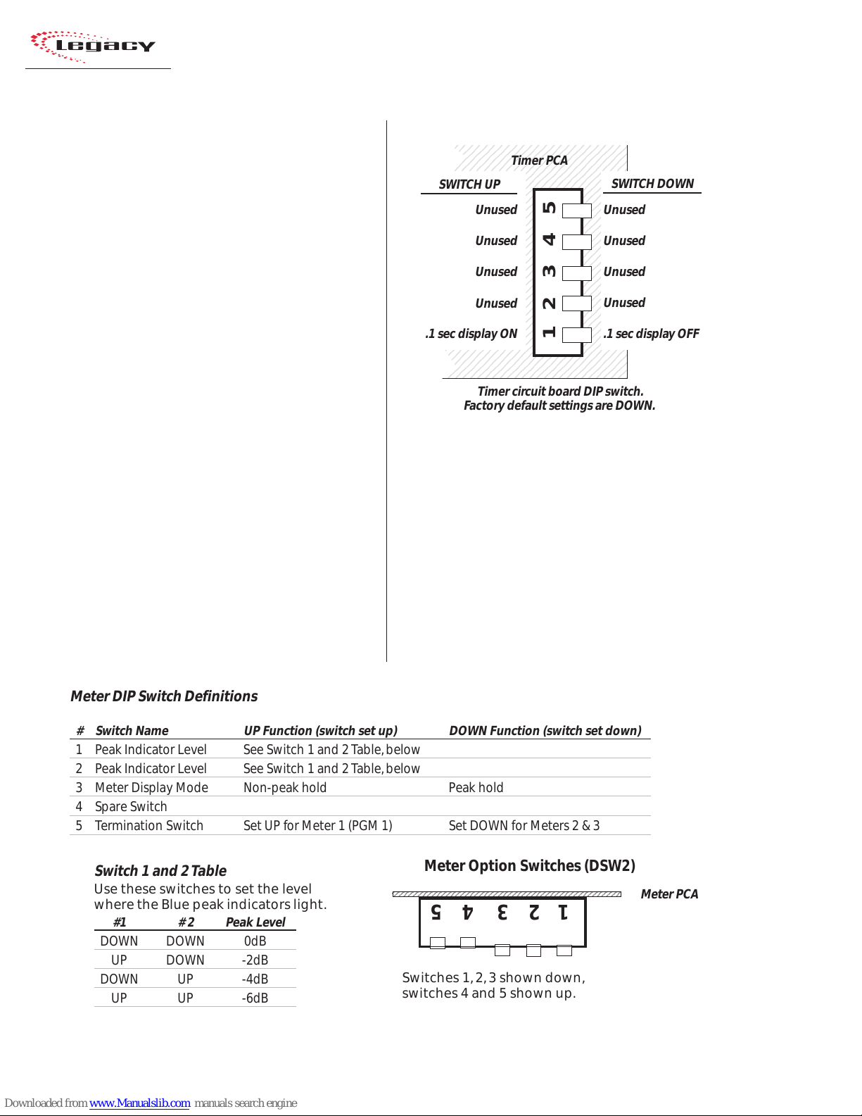
Clock Option Switches (DS1)
Clock PCA
SWITCH DOWN
24-hour
TC90
12-hour
TC89
ESE Disabled
(Slaved)
Unused
Unused
12 3 45
(Autonomous)
Unused
Unused
Clock circuit board DIP switch.
Factory default settings are DOWN.
With the clock set to autonomous mode, it must
• Use the right button (F ast) to scroll by minutes at a time.
• Use the middle button (Slow) to scroll by
seconds at a time.
• Use the left button (Hold) to synchronize
the console clock to an external time reference by setting the clock ahead of the
Setting the Clock
Clock Circuit Board, left front edge
Hold Slow Fast
2 Installation
6
6
6
6
6
6
6
6
6
6
6
6
6
6
6
6
6
6
6
6
6
6
6
6
6
6
6
6
6
6
1234567890123456789012345678901212345678901234567
1234567890123456789012345678901212345678901234567
external time reference, then press and hold
the HOLD button to freeze the time. When
the external time reference reaches the time
on the Legacy clock, release the HOLD button to start the clock.
When an ESE time-code signal is connected to
the BNC connector on the clock circuit board, and
slave mode is selected (DS1-3 is set UP), the clock
does not require setting. If the ESE time-code signal fails, the clock automatically defaults to its
internal crystal reference oscillator, flashing the
display colons to indicate the loss of time-code.
EVENT TIMER
The event timer displays time in minutes, seconds and tenths of seconds. T he only timer option
setting is whether to display the tenths of seconds
digit as the timer runs. DS1-1 (a DIP switch on
the timer circuit board, located behind the timer
display), sets whether the tenths are shown or not.
In the UP position, the tenths of seconds are displayed. In the DO WN position, the factory default,
the tenths do not display while the timer runs.
Note that the tenths of seconds are always shown
when the timer is in the Stop or Hold mode.
Event Timer Option Switches (DS1)
234567890123456789012345
234567890123456789012345
234567890123456789012345
234567890123456789012345
234567890123456789012345
234567890123456789012345
SWITCH UP
234567890123456789012345
234567890123456789012345
234567890123456789012345
234567890123456789012345
234567890123456789012345
234567890123456789012345
234567890123456789012345
234567890123456789012345
234567890123456789012345
234567890123456789012345
234567890123456789012345
234567890123456789012345
234567890123456789012345
234567890123456789012345
234567890123456789012345
234567890123456789012345
234567890123456789012345
234567890123456789012345
234567890123456789012345
234567890123456789012345
.1 sec display ON
234567890123456789012345
234567890123456789012345
234567890123456789012345
234567890123456789012345
Unused
Unused
Unused
Unused
Timer PCA
12345
SWITCH DOWN
Unused
Unused
Unused
Unused
.1 sec display OFF
Timer circuit board DIP switch.
Factory default settings are DOWN.
METER SETUP
The level at which the blue peak indicators turn
on, as well as the meter display mode (peak hold
or non-peak hold), is set separately for each meter
using DIP switches on the edge of each meter PCA.
To access the meter DIP switches, open the meter
panel by lifting it up and rotating it toward the
rear of the console until it stops. Each meter ’s DIP
switches are located on the underside of the meter
panel, directly below the right end of each meter.
Meter DIP Switch Definitions
# Switch Name UP Function (switch set up) DOWN Function (switch set down)
1 Peak Indicator Level See Switch 1 and 2 Table, below
2 Peak Indicator Level See Switch 1 and 2 Table, below
3 Meter Display Mode Non-peak hold Peak hold
4 Spare Switch
5 Termination Switch Set UP for Meter 1 (PGM 1) Set DOWN for Meters 2 & 3
Switch 1 and 2 Table
Use these switches to set the level
where the Blue peak indicators light.
#1 # 2 Peak Level
DOWN DOWN 0dB
UP DOWN -2dB
DOWN UP -4dB
UP UP -6dB
Meter Option Switches (DSW2)
Switches 1, 2, 3 shown down,
switches 4 and 5 shown up.
2-6
HARRIS CORPORATION
Revision B • 1/03
123 45
Meter PCA
2 Installation
Cabling and Wiring
Before installing the console, draw up a facility
wiring plan that lists the console interconnections
with all peripheral devices. Identify and create tags
for all audio and logic cabling. List each connection in a master facility wiring logbook to facilitate wiring installation, future system wiring
changes, equipment updates, and system troubleshooting.
Refer to the module Quick Connection Guides,
on pages 2-16 to 2-49, for information on each
audio and logic connection (including block diagrams for each logic interface connector) and on
each module’s setup DIP switches.
REQUIRED CABLES AND WIRE
The Legacy uses the following types of cables
and wires:
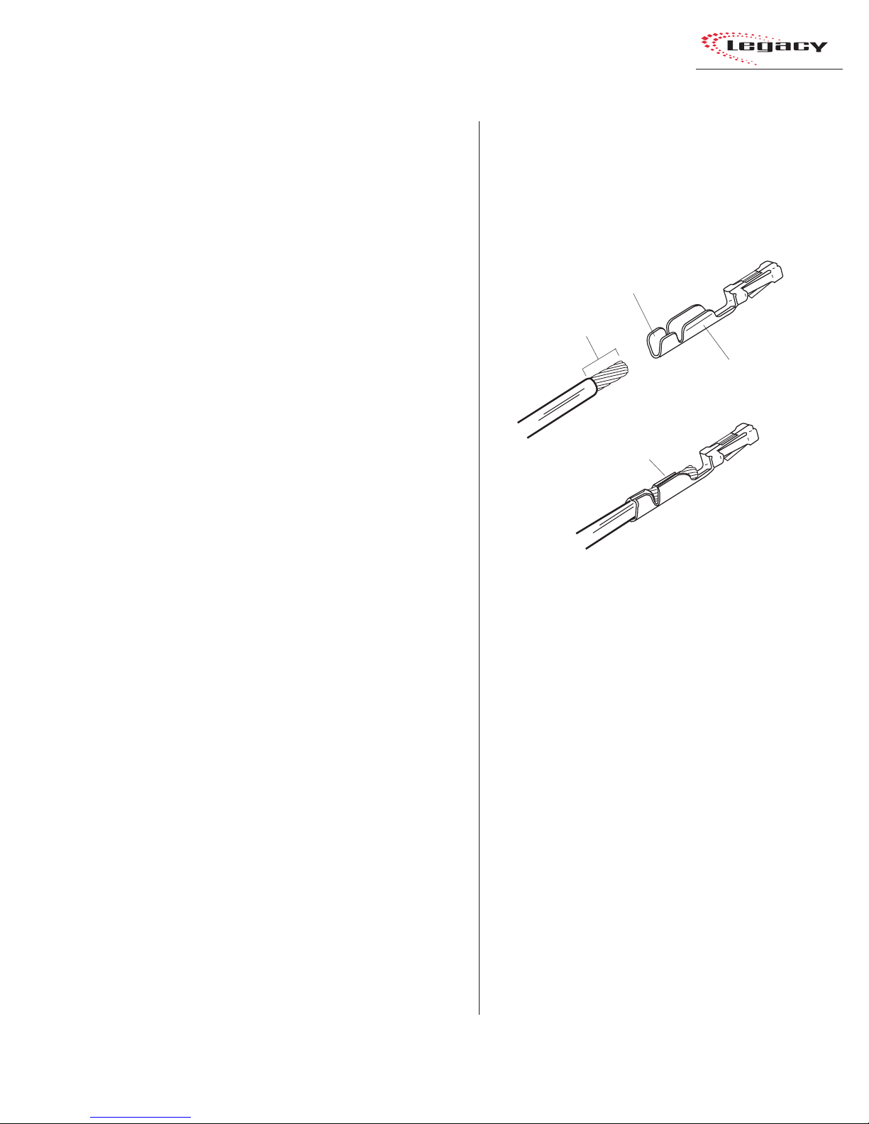
WIRE PREPARATION
All Legacy audio and logic wiring terminates
in AMP MOD IV receptacle contacts at the console. Stranded wire of 22 to 26 A WG, with insulation diameters of .040 to .060 inch, can be used
with the AMP MOD IV receptacle contacts.
Insulation Barrel
9/64” [3.57 mm]
Wire Barrel
Properly
Crimped Contact
• Analog audio connections require twoconductor, stranded, insulated, foil-shield
cable using a separate shield drain wire
(equivalent to Belden 8451, 9451 or 8761).
• AES/EBU connections require 110 ohm
two-conductor, stranded, insulated, foilshield cable containing a separate shield
drain wire (equivalent to Belden 1800A).
• Logic control cables require stranded, 22
AWG, multiple-conductor, non-shielded,
jacketed cable (equivalent to Belden 9423,
8457 or 9421). The number of conductors
used is determined by the application. Typically cables with five and eight wires are
most often used for constructing logic
cables. Even though there are eighteen distinct signals on the Logic Interface connector, only a handful are typically used for
any given application.
AMP MOD IV Receptacle Contacts
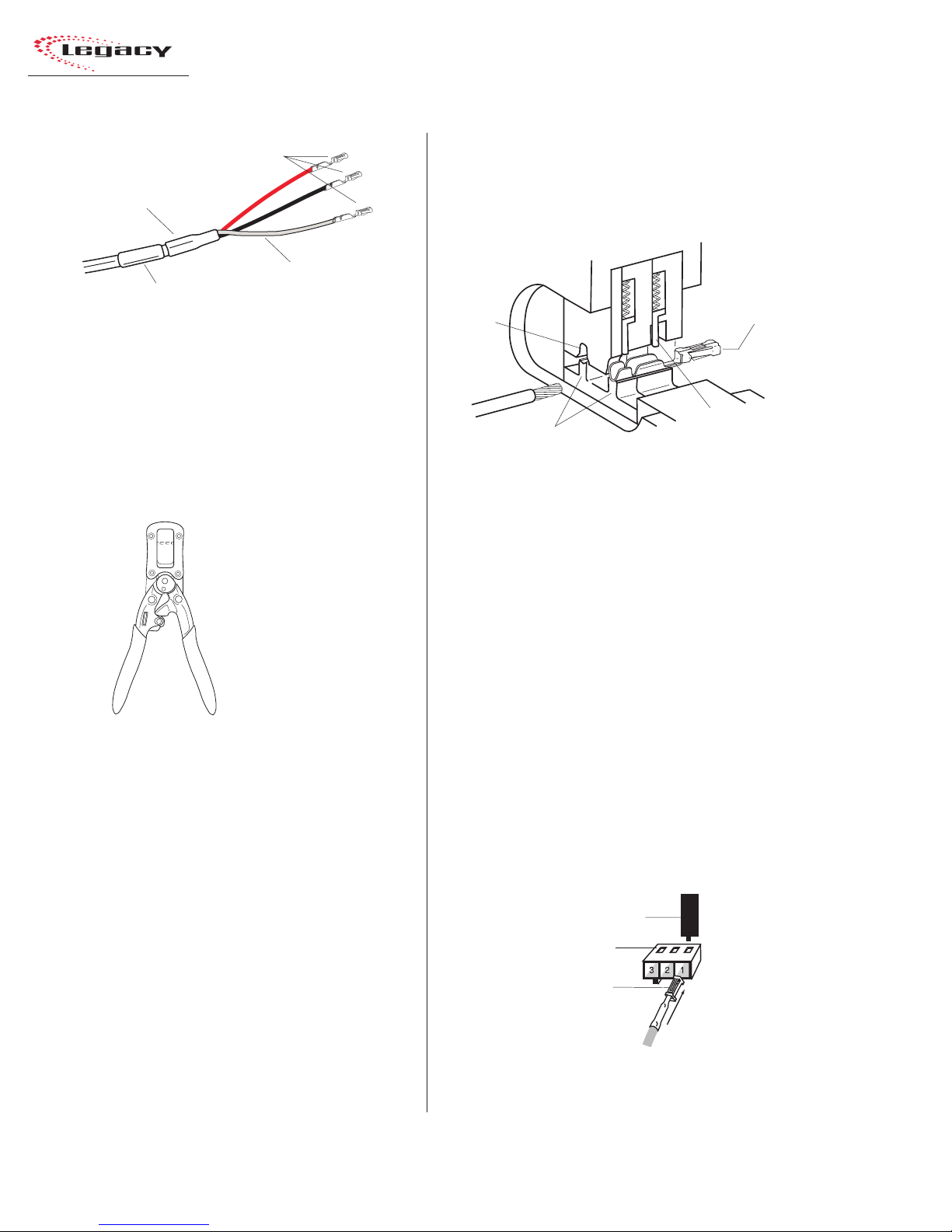
Follow these steps for audio wire preparation:
1 Strip the cable insulation jacket and foil shield
back 1½" [38.10 mm].
2 Remove the foil shield and sleeve the drain
wire with 20 AWG Teflon sleeving. Leave
9/64" [3.57 mm] of the drain wire exposed.
3 Cover the cut end of the jacket with 3/4"
[19.05 mm] of heat-shrink tubing. Shrink this
tubing, centered on the jacket cut end, to hold
the drain wire sleeving in place.
4 Strip the signal wire insulation back 9/64"
[3.57 mm].
5 Crimp the receptacle contact onto the wire
and insulation.
Audio Cable Shield Note: To ensure your in-
stallation follows recommended grounding procedures, you must sleeve all drain wires with Teflon sleeving and put heat shrink tubing over all
cable jacket cut ends to insulate the shield wire.
2-7
HARRIS CORPORATION
Revision B • 1/03
2 Installation
AMP MOD IV
Receptacle Contacts
3/4” [19.05 mm]
Shrink T ubing
Te flon Sleeving
Cable ID
Tag
over drai n wire
Audio Wire , ready for insertion into an
AMP MOD IV connector housing
Logic control cables are fabricated in a similar
manner to the audio wiring. Strip the jacket insulation back 1½" [38.10 mm], sleeve the cut end
with 3/4" [19.05 mm] of shrink tubing and strip
the insulation from each wire 9/64" [3.57 mm].
AMP MOD IV
Contact
Crimp Tool
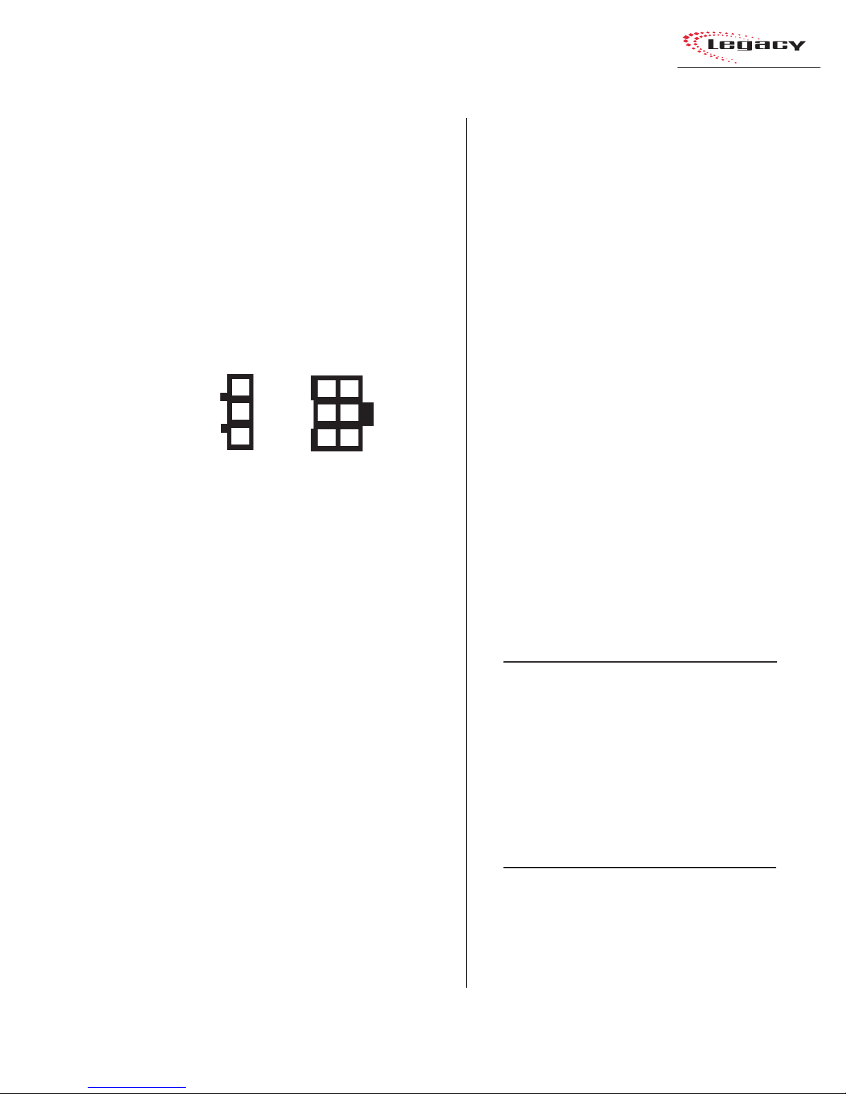
CRIMP TOOL OPERATION
A ratcheting AMP MOD IV crimp tool is
included in the tool kit. The tool crimps both the
insulation and wire barrels on the AMP MOD IV
receptacle contacts in one crimping action.
To use the ratcheting crimp tool:
1 Hold the crimp tool with the printed side up.
Insert the contact from the opposite side, with
the barrel openings up, until the insulation
barrel end is flush to the opening of the die.
Close the tool only until the anvil holds the
contact in place (Refer to the cutaway view
on this page).
2 Insert the stripped wire into the contact until
it hits the tool’s wire stop. Hold the wire in
place while squeezing the tool handles to
crimp the contact onto the wire. The tool
handles automatically release and spring open
after the crimp cycle is complete.
Printed
Side
Die
Anvils
AMP MOD IV
Receptacle
Contact
Wire Stop
Crimp Tool — Cutaway View
Once the contact has been crimped, insert and
lock the contact receptacle into the appropriate
connector housing following the pin-out diagrams
found in the Quick Guides on pages 2-16 to 2-49.
A receptacle contact is inserted into the housing with its locking tab side toward the locking
tab slots on the side of the connector housing. A
slight click can be heard when the contact’s locking tab springs up into the locking tab slot.
To remove a contact from a housing, the PRE70129 Contact Removal Tool (included in the PRE
76-2001 tool kit) is required. Insert the tool’s tip
into the locking tab slot and press the locking tab
down while lightly pulling on the wire to remove
the contact from the housing.
Contact Removal Tool
Locking Tab Slots
Locking Tab
Receptacle Contact
Insertion & Removal Detail
HARRIS CORPORATION
2-8
Revision B • 1/03
2 Installation
AUDIO CONNECTIONS
Audio connections take advantage of the threepins per row design of the three- and six-pin AMP
MOD IV housings. Three-pin housings are used
for balanced digital connections while six-pin
housings are used for balanced analog connections.
One important exception is the Mic Preamp module, which uses three-pin connectors for balanced
analog microphone inputs.
Pin Numbers for Analog &
Digital Audio Connectors
3
2
1
3-pin
connector
Pin numbering always shown from the wire insertion
end, oriented from the board operator’s perspective.
All audio wiring, when plugged into a module
connector , has this orientation:
• T he audio shields are on pins 1 and 4 (the
pins closest to the board operator).
• The audio low wires (typically the black
wires) are on pins 2 and 5 (the middle pins).
• The audio high wires (typically the red
wires) are on pins 3 and 6 (the back pins).
For stereo applications, the left channel wires
plug into the left column of pins and the right channel wires plug into the right column of pins (from
the board operator’s perspective).
When a six-pin input comes from a mono source
(such as an external microphone preamp output),
the left and right inputs should be paralleled together (pins 1 and 4 tied together, pins 2 and 5
tied together and pins 3 and 6 tied together). If
this is not done, then the module’s mode buttons
will have to be set for mono operation (see page
3-4 for L/R Mode information on the Universal
Input Module).
6
3
5
2
4
1
6-pin
connector
Analog Connections
There are no analog interstage patch points
within the Legacy input or output modules. To
use the console with a patch bay, connect the line
level outputs from the peripheral devices directly
to the patch bay. Normal these signals to the appropriate analog input modules.
Likewise, the Legacy’s analog outputs may be
routed through a patch bay normalled to standard peripherals such as analog on-air processing gear, recorders, telephone hybrids, etc.
The Mic Preamp module’ s line-level outputs (+4
dBu, nominal, balanced, mono outputs) can also
be routed through a patch bay normalled to an
input module, or to external mic processing.
When a mic processor with only a microphone
level input is used, the microphone is connected
directly to the mic processor, with the processor’s
line-level output either directly connected to an
input module (using the mono wiring pinout
shown below) or through a patch bay normalled
to an input module.
Two-Channel (Stereo)
Line Input or Output — 6-Pin Housing
Pin Signal Description
1 Shield for the left channel, or signal 1
2 Low (- input or output), left channel, or signal 1
3 High (+ input or output), left channel, or signal 1
4 Shield for the right channel, or signal 2
5 Low (- input or output), right channel, or signal 2
6 High (+ input or output), right channel, or signal 2
Single Channel (Mono)
Line Input — 6-Pin Connector
Pin Signal Description
1 Shield (connects directly to the chassis)
2 Low (- input) tied to pin 5
3 High (+ input) tied to pin 6
4 Shield (connects directly to the chassis)
5 Low (- input) from pin 2
6 High (+ input) from pin 3
2-9
HARRIS CORPORATION
Revision B • 1/03
2 Installation
Microphone Input — 3-Pin Connector
Pin Signal Description
1 Shield (connects directly to the chassis)
2 Low (- input)
3 High (+ input)
Digital Connections
Most of Legacy’s digital inputs and outputs are
wired like the Microphone Input shown above. One
exception is the RLS module, which uses 6-pin
connectors since it can be set for analog or digital
operation. When set for digital, the signals connect using pins 1, 2, and 3 of the connector.
The other modules with digital inputs or outputs; Universal Input, Telco/Codec, Output 1 and
2, use three-pin connectors like that shown abo ve.
The digital inputs accept AES-3 (AES/EBU) compatible signals and, as mentioned in the Unbalanced Connections section that follows, can also
accept S/PDIF signals in most cases.
Each digital output is an AES-3 compatible signal (nominal sample rate is 48 kHz, but some
outputs are switch selectable for 44.1 kHz) . AES3 output signals cannot connect directly to an
S/PDIF input. A signal translation interface is required to accomplish this function.
AES/EBU Digital Inputs and
External Clock Reference Input
Pin Signal Description
1 Shield (connects directly to the chassis)
2 Low (- input)
3 High (+ input)
AES/EBU Digital Outputs
Pin Signal Description
1 Shield for AES/EBU signal
2 Low (- output)
3 High (+ output)
UNBALANCED CONNECTIONS
Although all analog inputs and outputs are
active and balanced, unbalanced consumer or
“semipro” equipment can be connected to the con-
sole. For best results, connect an unbalanced device through an IHF-PRO match box and keep
the unbalanced cable lengths as short as possible.
If a match box is not available, connect an unbalanced device to a Legacy input using the following illustration.
Connecting an Unbalanced Device
to a Legacy Analog Input
From the
Unbalanced
Device
R
L
Shields
Console
Balanced
Input
3
6
2
5
1
4
When an unbalanced device must connect to a
Legacy balanced analog output, and an IHF-PRO
match box is not available, do not tie the low (-)
and shield pins together to “unbalance” the signal. The low output pin must always be left “floating” when unbalancing a Legacy output, as shown
in the following illustration.
Connecting an Unbalanced Device
to a Legacy Analog Output
(Nominal Output is -2 dBu)
Console
Balanced
Output
3
6
2
5
1
4
(Make no connections to pins 2 & 5)
To the
Unbalanced
Device
L
R
Shields
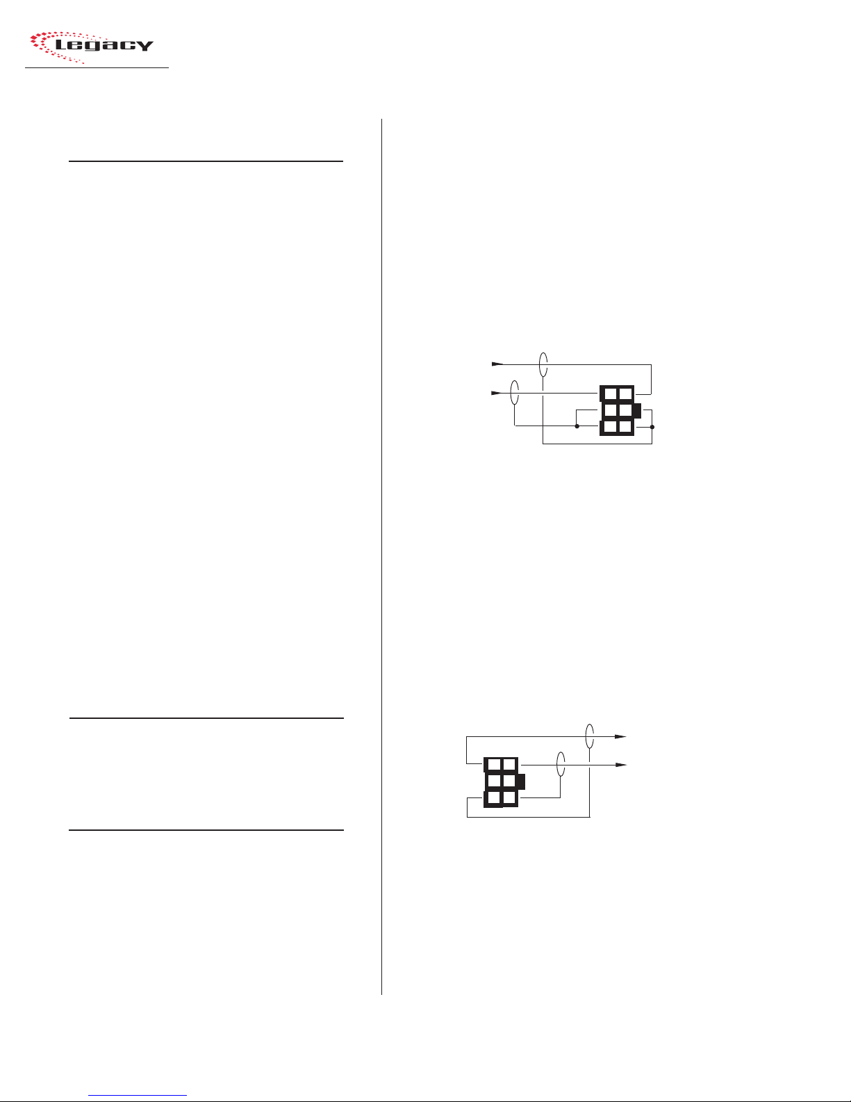
S/PDIF Signals
Digital devices with only an S/PDIF digital output can connect to a Legacy input, but only when
a 249 ohm resistor is added to load the 75 ohm
S/PDIF cable. Install the resistor at the AMP MOD
IV housing per the illustration on the next page.
HARRIS CORPORATION
2-10
Revision B • 1/03
2 Installation
Connecting an S/PDIF Device to
a Legacy AES/EBU Input
From
S/PDIF
Device
Signal
Shield
249 ohm resistor
Console
AES/EBU
Input
3
2
1
An unbalanced-to-balanced line transformer
can also be used to interface an S/PDIF signal.
Note 1: A signal conversion interface must be
used to connect an AES/EBU output to a S/PDIF
input.
Note 2: Some S/PDIF signals may not work with
the Legacy’s inputs, even with the additional load
resistor or a transformer , because of nonstandard
levels or protocols in the S/PDIF product.
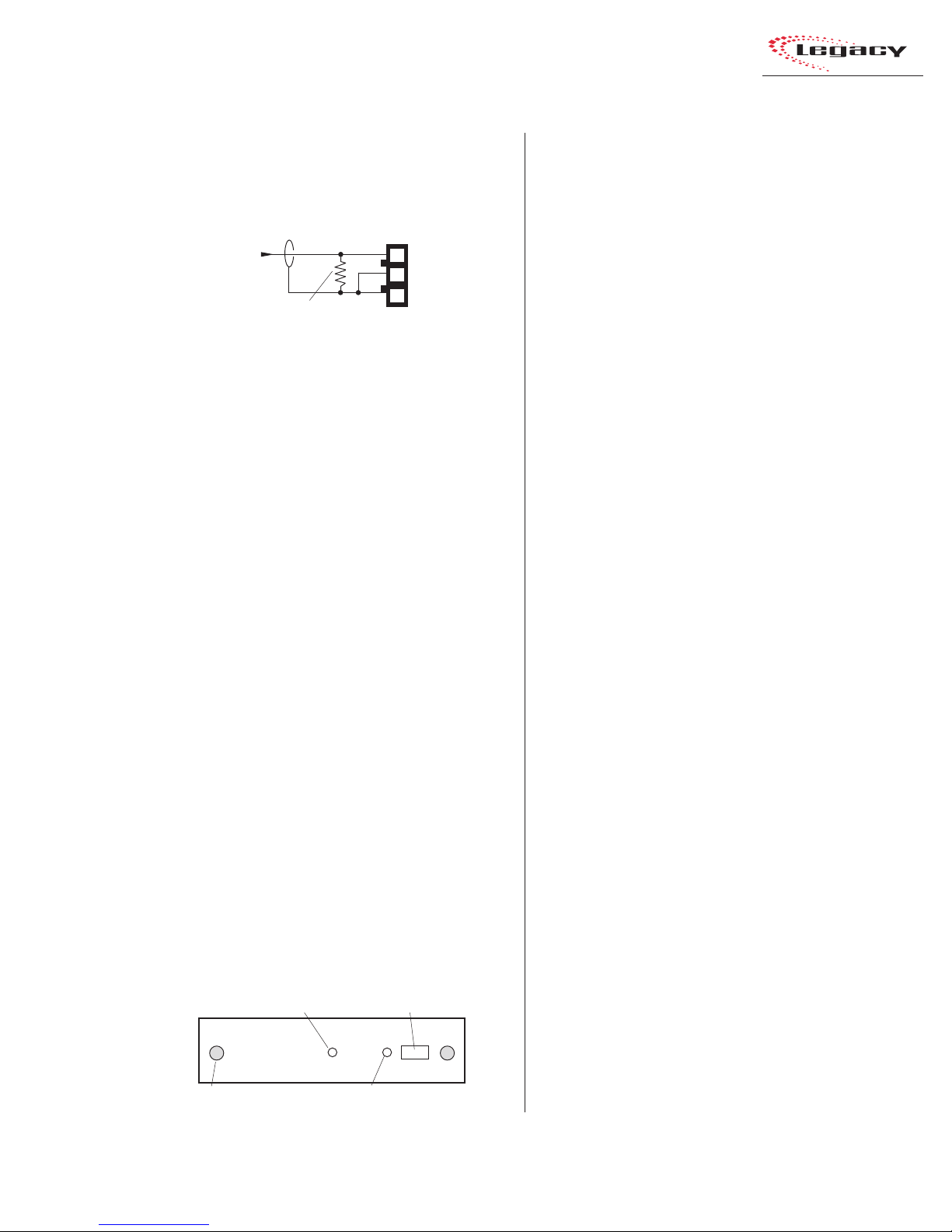
DIGITAL CLOCK REFERENCE
The Legacy has an internal clock for sample
rate timing, with sample rate converters on each
input to synchronize/convert external digital signals to the console’s internal 48 kHz sample rate.
The console can automatically synchronize to an
external AES-3 digital reference signal (of 48 kHz,
±100 ppm only) through a 3-pin connector on the
left DSP card (the DSP cards are along the back
of the mainframe, below the meter panel).
A green LED next to the connector indicates
whether the console is using internal reference
(LED is lit), or using the external reference (LED
is off). If an external reference signal is connected,
and yet the LED is still lit, this indicates the refer ence signal is not present or is out of range.
Master DSP Card
LED — When lit, indicates
the card is operating
Thumb
screw (x2)
LED — When lit, indicates the console
is using an internal reference
3-pin digital connector
(Master DSP card only)
LOGIC CONNECTIONS
Legacy modules have built-in logic I/O interfaces that can control, or be controlled by,
peripheral devices connected to the console. For
example, a CD pla yer connected to a module can
be automatically started when the module is
turned on. Then, at the end of the cut, the CD
Player logic can turn the module audio off and
control the off button illumination to indicate that
the cut has been played.
When a mic remote control panel is connected,
its On, Off, Cough, and Talkback buttons control
the module while tally outputs from the module
control the button tallies on the mic panel.
Legacy modules have the following logic connectors:
• Universal Input modules have two LOGIC
I/O connectors for controlling the devices
connected to the A and B inputs.
• Telco modules have a single LOGIC I/O
connector for controlling the device connected to the module.
• T he Meter Switcher module has three EXT
TIMER connectors for resetting studio or
producer timers, and the connectors for the
factory-installed wiring that ties the mainframe to the meter panel.
• The Control Room module has a LOGIC
connector for the warning light and talkback outputs and the remote mute and dim
inputs. A CUE CNTL connector allows external cue input control.
• T he optional Studio module has one LOGIC
connector for the studio warning light and
talkback outputs and the remote mute and
dim inputs and tally outputs. An EXTERNAL connector has the talkback commands and the audio (both to and from)
for an external location.
2-11
HARRIS CORPORATION
Revision B • 1/03

2 Installation
MODULE QUICK GUIDES
Pages 2-16 to 2-49 have Quick Guides to configuring each module’s logic connections and DIP
switch settings. Each guide includes the audio and
logic connector pinouts and signal descriptions,
DIP switch setting definitions and, for some modules, logic block diagrams.
Module Quick Guides:
• Mic Preamp: pages 2-16 & 2-17
• Universal Input: pages 2-18 to 2-21
• Telco/Codec: pages 2-22 to 2-25
• RLS: pages 2-26 & 2-27
• Meter Switcher: pages 2-28 to 2-30
• Control Room: pages 2-32 to 2-37
• Studio: pages 2-38 to 2-45
• Output 1: pages 2-46 & 2-47
• Output 2: pages 2-48 & 2-49
Pages 2-50 to 2-55 show examples of typical
logic connections to the Universal Input module
for a mic remote control panel, a CD player, and a
digital delivery system.
Note: To completely isolate the console from the
peripheral device, use only the opto-isolated control input and output connections since the Logic
Ground and Logic Supply +5VDC connections are
referenced to the console’s logic power supply and
ground.
Connect these only to isolated devices, such as
a mic control panel or other Harris Accessory
Panel. Connecting the logic ground to a nonisolated peripheral device can result in a ground
loop between the console and the peripheral
device.
UNIVERSAL INPUT LOGIC INTERF A C E
A block diagram of the Universal Input module
logic interface is shown on page 2-13. Logic outputs (shown on the right side of the illustration)
are isolated from the peripheral device by six solidstate “relays . ” T he “relay contacts” can switch logic
voltages up to 60 volts at 350 mA.
Pressing the On button generates a 220 ms contact closure from pin 5 (Start Command Pulse). A
sustained contact closure while On is available on
pin 23 (Start Command Sustained). It stays closed
as long as the module is On. Pressing the Off button generates a 220 ms closure from pin 4 (Stop
Command Pulse). These three command outputs
are tied together at pin 13 (Command Common).
Module DIP switches DS2-2 (for the A input)
and DS4-2 (for the B input), set whether a single
pulse is output when the module status changes
(Off to On, or On to Off), or if each additional
press of the On or Off buttons produces another
contact closure. The default setting (switch 2 set
to OFF) is a single contact closure. When DS2-2
or DS4-2 is set to On, then each additional press
of the On or Off button produces another 220 ms
contact closure.
T he remaining outputs; Logic Activ e/Cue Tally
[pin 15], On Tally [pin 17], and Off Tally [pin 16],
are tied together at Tally Common [pin 14]. They
present sustained logic outputs for each function.
There are six logic inputs on the left side of the
illustration: Reset/Talk to Studio, Ready/Talk to
External, On, Off, Cough, and Talk to Control
Room/Ext. Cue. T hese inputs are opto-isolated and
current limited so any logic voltage from +5 to
+40 VDC can be used.
Reset/Talk to Studio, and Ready/Talk to External have both high (+) and low (-) input pins so
that either polarity logic can be used. The other
inputs use active low logic (pull to ground) that
typically come from a mic control panel (although
On and Off could be triggered by a peripheral
HARRIS CORPORATION
2-12
Revision B • 1/03
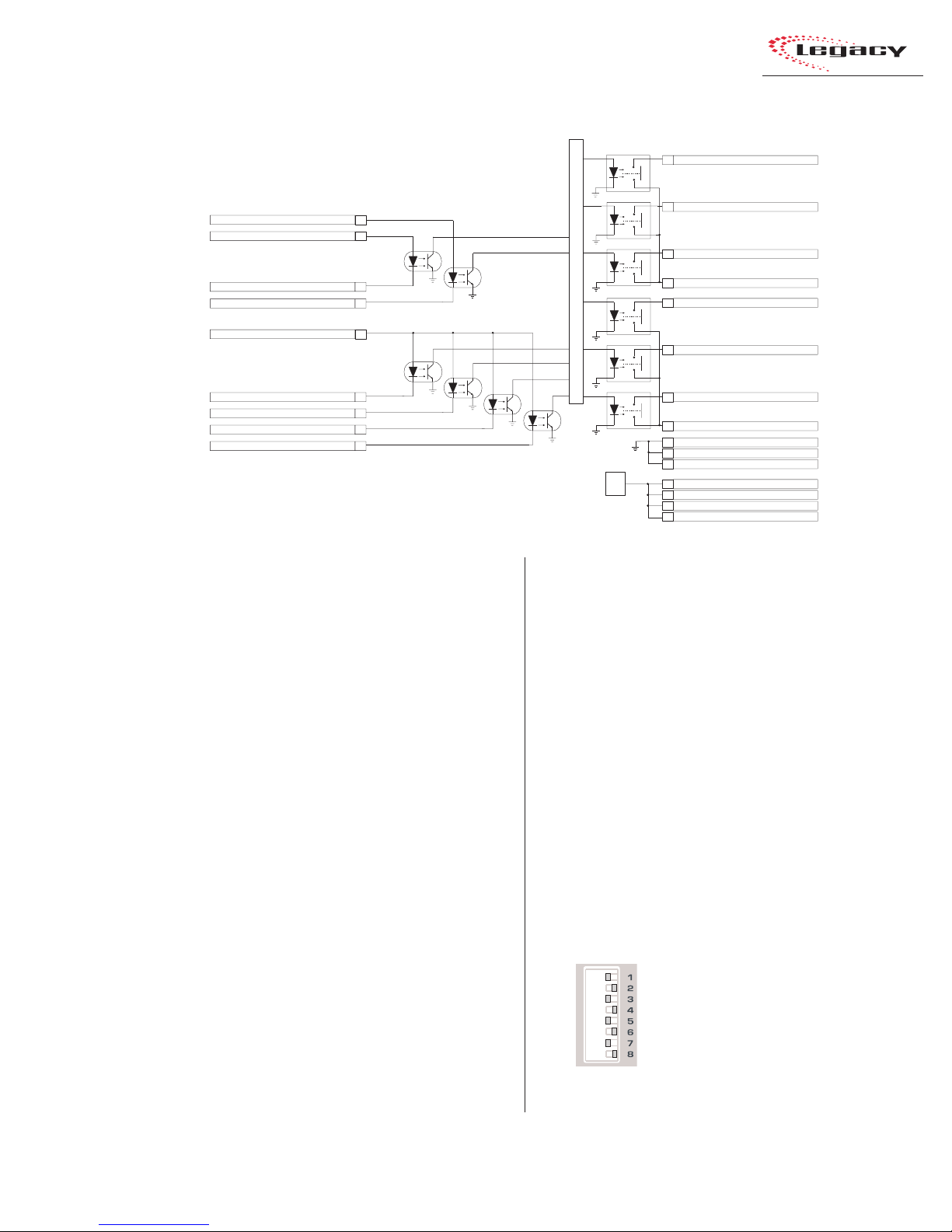
Block Diagram, Universal Input
Module Logic Interface
MIC: Talk to Studio (+) LINE: Reset Input (+)
MIC: Talk to Ext. (+) LINE: Ready Input (+)
MIC: Talk to Ext. (-) LINE: Ready Input (-)
MIC: Talk to Studio (-) LINE: Reset Input (-)
22
24
21
19
2 Installation
Start Command Pulse
5
Stop Command Pulse
4
Start Command Sustained
23
Command Commo n
Internal Logic
13
MIC: Logic Active Tally LINE: Cue Tally
15
Activate Logic Inputs(+)
On Input (-)
Off Input (-)
Cough Input (-)
MIC: Talk To C/R (-) LINE: Cue Input (-)
Notes:
Opto-Isolator inputs can handle +5 to +40 VDC logic
Opto-Isolator outputs can handle up to 60 volts or 350 mA
18
7
8
9
20
device). T o use these inputs, pin 18 (Activate Logic
Inputs) must be jumpered to the + logic voltage.
Typically this is pin 6 (Logic Supply +5 VDC), but
it can also be supplied by the peripheral device.
The Reset/Talk to Studio and Ready/Talk to
External inputs can use either active low logic (pull
to ground) or active high logic (pull to +VDC) from
peripheral devices. Which function is active is determined by the setting of DS1/DS3 s witches 2, 3,
and 5. When all are off, the module is set as a
Line Input, and the commands are Reset and
Ready. When DS1/DS3 switch 2, 3, or 5 is on,
then the module is set as a Mic Input and the commands are Talk to Studio and Talk to External.
With active high logic, Ready/Talk to External
(-) and Reset/Talk to Studio (-) are tied to logic
ground on the peripheral device. Ready/Talk to
External (+) and Reset/Talk to Studio (+) then
connect to the appropriate logic outputs on the
peripheral device.
When active low logic is used by the peripheral
device, Read y/Talk to External (+) and Reset/T alk
to Studio (+) connect to the logic supply voltage
On Tally
17
Off Tally
16
Tally Common
14
Logic Ground
1
Logic Ground
2
Logic Ground
+5V
Reg.
3
6
Logic Supply +5VDC
10
Logic Supply +5VDC
11
Logic Supply +5VDC
12
Logic Supply +5VDC
on the peripheral device, and Ready/Talk to External (-) and Reset/Talk to Studio (-) connect to
the appropriate logic outputs.
Pin 15’s signal (Logic Active Tally / Cue Tally)
changes depending upon whether the channel logic
switches (DS1/DS3) are set to mute any location.
When a mute is set (DS1/DS3, switch 2, 3, or 5 is
set to On), the module is set as a microphone and
the Logic Active Tally output (pin 15) is closed
when that input (input A for DS1 or input B for
DS3) is active. When no mute is set, the module is
set for line logic and pin 15 becomes a Cue Tally.
Setting DIP Switches
When referring to a module’s DIP switch setting, a switch is Set to Off when it is to the right
and it is Set to On when it is to
the left (orientation is from the
board operator’s perspective).
In the illustration, all odd numbered switches are shown set to
On = set Left
Off = set Right
On and all even numbered
switches are shown set to Off.
2-13
HARRIS CORPORATION
Revision B • 1/03
2 Installation
Universal Input Module Logic
and Microphones
The three main functions of microphone logic
are to automatically mute the monitor speakers
in the room with the “hot” mic, to command the
appropriate hot mic warning light, and to activate such microphone functions as talk to control
room and cough.
The warning commands come from the Control
Room or Studio modules, but it is DS1 (for the A
input) and DS3 (for the B input), switches 2, 3, or
5, on each Universal Input module that tell the
monitor modules whether a mic is located in the
control room, a studio, or an external location.
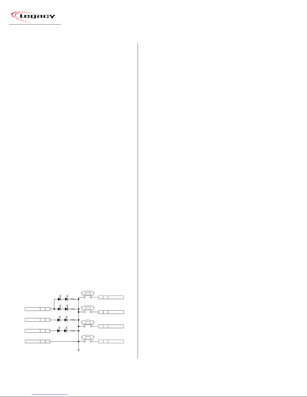
Pages 2-50 and 2-51 summarize setting up a
Universal Input module as a microphone input,
utilizing a PRE99-1198 Mic Panel (simplified
schematic shown below).
The Mic P anel connects to the module’ s LOGIC
I/O connector. To enable the remote control
inputs (On, Off , Cough, Talk to C/R), pin 18 (Activate Logic Inputs) has to be jumpered to pin 6,
10, 11, or 12 (Logic Supply +5VDC).
T he On Tally output drives the LEDs in the On
button and the Off Tally drives the LEDs in the
Off button. The other LEDs (Cough and Talkback)
connect internally to the Logic Supply +5 VDC.
Mic Control Panel
(Simplified Schematic
for PRE99-1197 or PRE99-1198)
TAL KB ACK
COUGH
ON
OFF
S1
8 J1 TALK TO C/R
S2
7 J1 COUGH
S4
6 J1 ON
S3
5 J1 OFF
AMBER (TALKBACK)
AMBER (COUGH)
V+ SUPPLY J1 4
ON TALLY J1 3
OFF TALLY J1 2
LOGIC GND J1 1
AMBER (OFF)
CR3 CR6
CR4 CR5
RED (ON)
CR8 CR7
CR1 CR2
GNDD
J1: TO/FROM CONSOLE CHANNEL LOGIC
All LEDs are tied to Logic Ground (pins 1, 2 or 3
on the LOGIC I/O connector).
To construct a custom mic control panel like
that shown on this page, use SPST (single pole,
single throw) momentary contact switches with
LED or lamp indicators. Lamps must be 6.3 v olt
type with a current draw of under 50 mA.
Tie one side of each switch and lamp to Logic
Common (pin 1, 2 or 3 on the LOGIC I/O connector). The other side of the Cough and Talkback
lamps tie together to Logic Active T ally (pin 15).
Each switch is tied to its logic counterpart (the
On switch goes to the On (-) input, pin 7, the Off
switch goes to Off (-) input, pin 8, etc.). T he on/off
lamps are tied to their Tally outputs (On lamp to
On Tally, pin 17; Off lamp to Off Tally, pin 16).
Tally Common (pin 14) is jumpered to Logic
Supply +5VDC (pin 6, 10, 11 or 12) at the LOGIC
I/O connector. Pin 18, Activate Logic Inputs (+)
is also jumpered to Logic Supply +5VDC (typically pin 6 is used).
Input Module Logic (Universal Input and
T elc o ) and Per ipheral De vices
Peripheral devices are controlled through the
Start and Stop Command Pulses, or through the
Start Command Sustained logic, and the Commands Common connections.
In the basic logic connection example on pages
2-52 and 2-53, activ e low logic is used, thus Command Common is connected to the logic ground
on the peripheral device (labeled Command Common on the Denon CD player in the example).
In the complex logic example shown on pages
2-54 and 2-55, active high logic is used, thus
Command Common connects to Logic Supply
+5 VDC.
Note: This voltage is more typically supplied
directly by the peripheral device in order to
prevent ground loops.
HARRIS CORPORATION
2-14
Revision B • 1/03

2 Installation
Peripheral devices control the module through
the Reset and Ready logic inputs. In the example
on pages 2-52 and 2-53, only the Ready function
is used. The Ready function performs an audio
reset, which turns off the module without generating a Stop Command Pulse. In addition, it also
controls the Off lamp illumination.
In the example on pages 2-54 and 2-55,
Reset (+) and Ready (+) connect to Logic Supply
+5VDC on the module. The Ready (-) command
and the Reset (-) command are pulled low by the
active low logic relay outputs on the peripheral
device, which all tie to the module’ s Logic Ground
(pin 1).
For peripheral devices that require a stead y on
signal, the Start Command Sustained output can
be used.
Additional Logic Connections
There are additional logic connections on the
Meter Switcher module, Control Room module,
and optional Studio module
Three 3-pin connectors on the Meter Switcher
module interface remote timers so they can be
reset by the console timer reset logic. The Meter
Switcher module also has factory-installed cabling
for the timer, the talkback mic, and the digital
level meters. For more information on the Meter
Switcher module’s logic connections and settings,
see pages 2-28 to 2-30.
A 14-pin connector on the Control Room module carries the logic interface for the Control Room
warning light, remote mute and dim inputs, and
the mute, dim and talkback tallies. The 8-pin Cue
Cntl connector on the Control Room module has
the External Cue logic interface. For more information on the Control Room module’s logic connections and settings, see pages 2-32 to 2-36.
The optional Studio module includes a 14-pin
connector to control the studio’s logic, including
warning lights, mutes, and dims. The Studio mod-
ule also has a 16-pin connector for the audio and
logic for an external site’s talkback audio and control. F or more information on the Studio module’ s
logic connections and settings, see pages 2-38 to
2-45.
2-15
HARRIS CORPORATION
Revision B • 1/03
2 Installation
QUICK GUIDE TO THE MICROPHONE PREAMPLIFIER MODULE
Each Legacy Preamplifier module can contain two separate PCAs with five mic preamps on each
assembly. The console comes standard with one Preamp module with one five-input mic preamp PCA
that allows an additional five-input preamp PCA to be retrofitted. A second Mic Preamp (with either
five or ten inputs) can be added to the console.
Each Mic Preamp PCA has five 3-pin analog microphone input connectors and five 6-pin analog
audio output connectors. Each input connects to a separate mic preamp driving its own line-level
balanced analog output connector. The connectors are hidden by the meter panel in normal operation
and the trimpots, visible to the operator, are covered by a security cover.
INPUTS
1 - 10 — The 3-pin analog inputs accept mono microphone signals.
Connect only low impedance, balanced, dynamic or condenser
microphones, with nominal mic output levels of -65 to -30 dBu, to these
inputs.
Analog Mic Inputs
High (+)
Low (-)
Shield
3
2
1
(wire insertion end view)
OUTPUTS
1 - 10 — The 6-pin analog outputs are wired in parallel (mono) using
the standard pinout sequence. This allows these outputs to connect directly
to Universal Input modules without requiring any setting changes be made
to the Input Mode from a standard stereo input. The preamp output signal
level is +4 dBu.
Analog Preamp Outputs
Left Hig h (+ )
Left Low ( - )
Shield
3
6
Right High ( + )
2
5
Right Low (-)
1
4
Shield
HARRIS CORPORATION
(wire insertion end view)
2-16
Revision B • 1/03
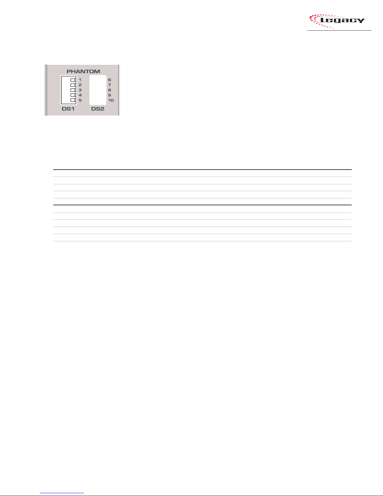
2 Installation
MICROPHONE PREAMPLIFIER MODULE SWITCHES
PHANTOM
DS1 — These five DIP switches control the phantom power for the mic inputs 1 - 5. The factory
default for the phantom power is off per the Microphone Preamplifier Module Switch Definitions
table shown below.
DS2 — These five optional DIP switches set the phantom power for optional mic inputs 6-10.
Microphone Preamplifier Module Switch Definitions
# Switch Name ON Function (set to operator’s left) OFF Function (set to operator's right)
1 Mic Input #1 Phantom power on Phantom power off
2 Mic Input #2 Phantom power on Phantom power off
3 Mic Input #3 Phantom power on Phantom power off
DS1
4 Mic Input #4 Phantom power on Phantom power off
5 Mic Input #5 Phantom power on Phantom power off
6 Mic Input #6 Phantom power on Phantom power off
7 Mic Input #7 Phantom power on Phantom power off
8 Mic Input #8 Phantom power on Phantom power off
9 Mic Input #9 Phantom power on Phantom power off
DS2 (optional)
10 M ic Input #10 Phantom power on Phantom power off
2-17
HARRIS CORPORATION
Revision B • 1/03
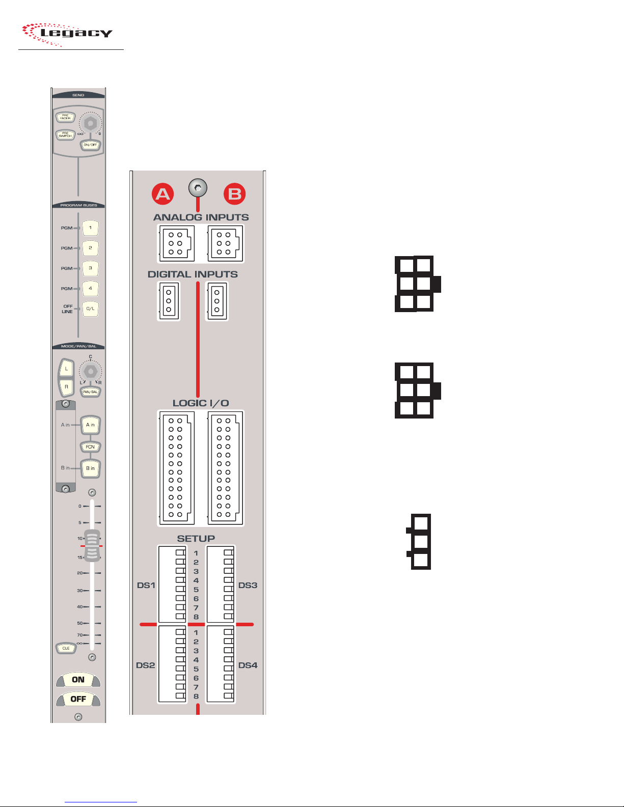
2 Installation
QUICK GUIDE TO THE UNIVERSAL INPUT MODULE
Six connectors come standard on each Universal Input module: two 6-pin analog audio input connectors, two 3-pin digital audio input connectors, and two 24-pin logic connectors. The connectors are
hidden by the meter panel in normal operation.
AUDIO
ANALOG INPUTS A & B — The 6-pin analog inputs accept stereo or
mono line level signals. Mono signals, like those from a preamplified
microphone, should be paralleled to the left and right inputs.
Analog Inputs - Stereo
Left High (+ )
Left Low (- )
Shield
3
6
Right High (+)
2
5
Right Low (-)
1
4
Shield
(wire insertion end view)
Analog Inputs - Mono
3
High (+)
Low (-)
Shield
6
High (+)
2
5
Low (-)
1
4
Shield
(wire insertion end view)
DIGITAL INPUTS A & B — The two 3-pin digital inputs accept AES-3
(AES/EBU) or S/PDIF signals (when the circuit shown on page 2-11 is used).
Digital Inputs
High (+)
Low (-)
Shield
3
2
1
HARRIS CORPORATION
(wire insertion end view)
LOGIC
LOGIC I/O A & B — Two 24-pin logic connectors allow separate A/B
input control of peripheral devices or remote panels connected to the A and
B inputs. For additional information, see pages 2-20 and 2-21
2-18
Revision B • 1/03
 Loading...