

Page 1
harman/kardon
GLA-55
GLA-55/230
Two-Piece 2.0 Multimedia Speaker System
SERVICE MANUAL
harman/kardon, Inc.
8500 Balboa Blvd.
Released 2009 Northridge, CA. 91329 Rev0 4/2010
Discontinued XXXX
Page 2

GLA-55 harman/kardon
1
CONTENTS
BASIC SPECIFICATIONS………………………………..1
FEATURES……..….…………………………..…………..2
PACKAGING………………………..….…………………..3
QUIC K SETUP/ C O NNECTI O NS………………………….4
OPERATION…..……………………...……………………5
EXPLODED VIEW (MASTER, RIGHT)…..….….. ……..6
MATCHING PARTS LIST (MASTER, RIGHT) …….…....7
EXPLODED VIEW (SLAVE, LEFT)………… …………..9
MATC H I NG PART S LIST (SLAVE, LEFT) …………......10
DISASSEMBLY INSTRUCTIONS………..……….….…11
DISASSEMBLY IMAGE AIDS……………….…….….…14
NOTE ON ELECTRONICS……………………….…..…16
ELECTRICAL PARTS LIST…….…………………….…17
PCB DRAWINGS……………………………..……….…23
SCHEMATICS……………………………………..…..…24
GLA-55 SPECIFICATIONS
Power Output 56 Watts RMS per channel
Frequency Response (–10dB) 35Hz – 20kHz (- 10dB)
Dimensions (W x D x H) 5 x 10.5” (127mm x 267mm)
Weight per Speaker 2.5lb (1.2kg)
Input Impedance 5k ohms
Signal-to-Noise Ratio 85dB A-weighted
Input Requirement Main connection – 1/8" (3.5mm) mini stereo jack
Input Sensitivity 250mV for rated power
Maximum Power Consumption 60 Watts
Driver Complement Atlas™ AL Woofer; CMMD® Lite Tweeter
Voltage Input 120V AC (US), 100V AC (Japanese), 230V AC (Europe)
harman/kardon, Inc. continually strives to update and improve existing products, as well as create new ones. The specifications and
construction details in this and related publications are therefore subject to change without notice.
Page 3

Features
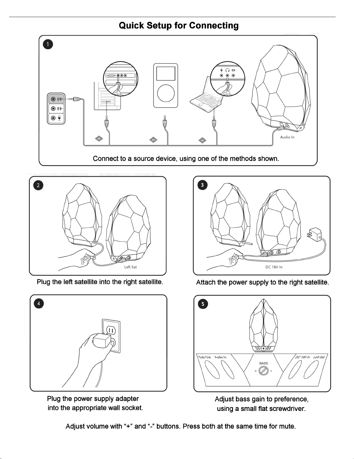
Compatibility
• The GLA-55 speaker system is compatible with virtually any audio device with an analog output. A stereo mini jack connection allows
you to enjoy high-quality audio from a variety of devices such as MP3 and CD players, desktop computers (all platforms), satellite radio
and laptops.
Easy-to-use music controls
• Just a touch increases or decrease the volume. Touch both volume controls simultaneously to mute the audio output. Touch again to
unmute. An LED on the front of both satellites lets you know whether the system is on, on standby, or muted.
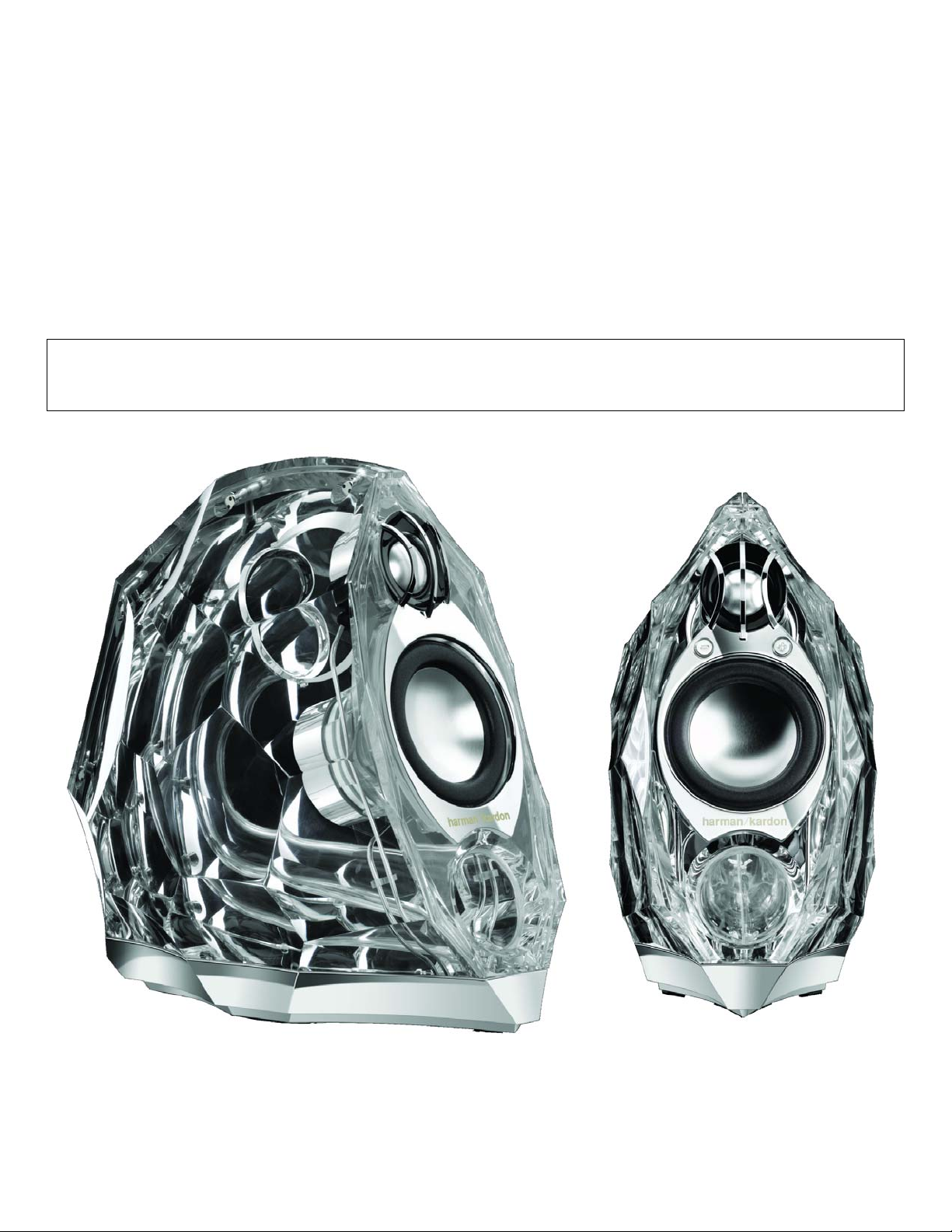
Beauty and sound
• The GLA-55 is a stylized multimedia focal point. Not just an exceptionally high-quality audio system, it’s also – from its chrome base to
its fully visible audio engine and port – a piece of art. No detail is left unrefined. The faceted cut-glass enclosures are a first in desktop
audio systems, and will integrate beautifully with home and office décor.
Digital power and DSP
• The GLA-55 system delivers with a powerfully tuned digital audio path. The clean and compact digital amplification, coupled with
DSP (digital signal processing) equalization, efficiently provides GLA-55 transducers with cool-running power.
Subwoofer output
• The GLA-55 systems packs a powerful punch on its own but, for added bass response, the subwoofer output allows connection to most
stand-alone subwoofer systems.
Advanced technology
• GLA-55 speakers feature many proprietary technologies to provide the highest quality sound, including astonishing bass and clear,
accurate sound in any location.
• Atlas
TM
AL and CMMD® Transducers – The CMMD drivers provide accurate high frequencies but are also capable of low-frequency
extension to four octaves; the Atlas AL drivers are capable of nearly 1" peak-to-peak travel for tight, accurate bass reproduction. Their
pairing provides a full, rich frequency response from the lowest bass to the highest highs.
• Slipstream Port Design – The GLA-55 port minimizes boundary layer separation, providing high-output bass with low distortion.
• COE (Computer-Optimized Equalization) – The GLA-55 system equalization is computer-optimized to provide a rich, complete sound-
stage over a wide range of listening positions.
• OCT (Optimized Compression Topology) – GLA-55 speakers utilize a proprietary compression technology, which ensures clean,
accurate sound at high output levels.
Detailed technical specifications
/ GLA-55
Two-piece speaker system
Manufacturer: Harman Kardon, Inc.
Model Name: GLA-55
Available In: Clear with chrome accents
Input Requirement: Main connection – 1/8" (3.5mm)
mini stereo jack
Drivers: 1 x CMMD, 1 x Atlas AL driver
per satellite
Power: 56 Watts per satellite
Frequency Response: 60Hz – 20kHz
Dimensions (W x H): 5.5" x 10.5" (140mm x 270mm)
Weight: Approx 2.5 lb (1.2kg)
Input Impedance: 5k ohms
Voltage input: 120V AC (US), 100V AC (Japanese),
230V AC (Europe)
GLA-55 harman/kardon
2
Page 4
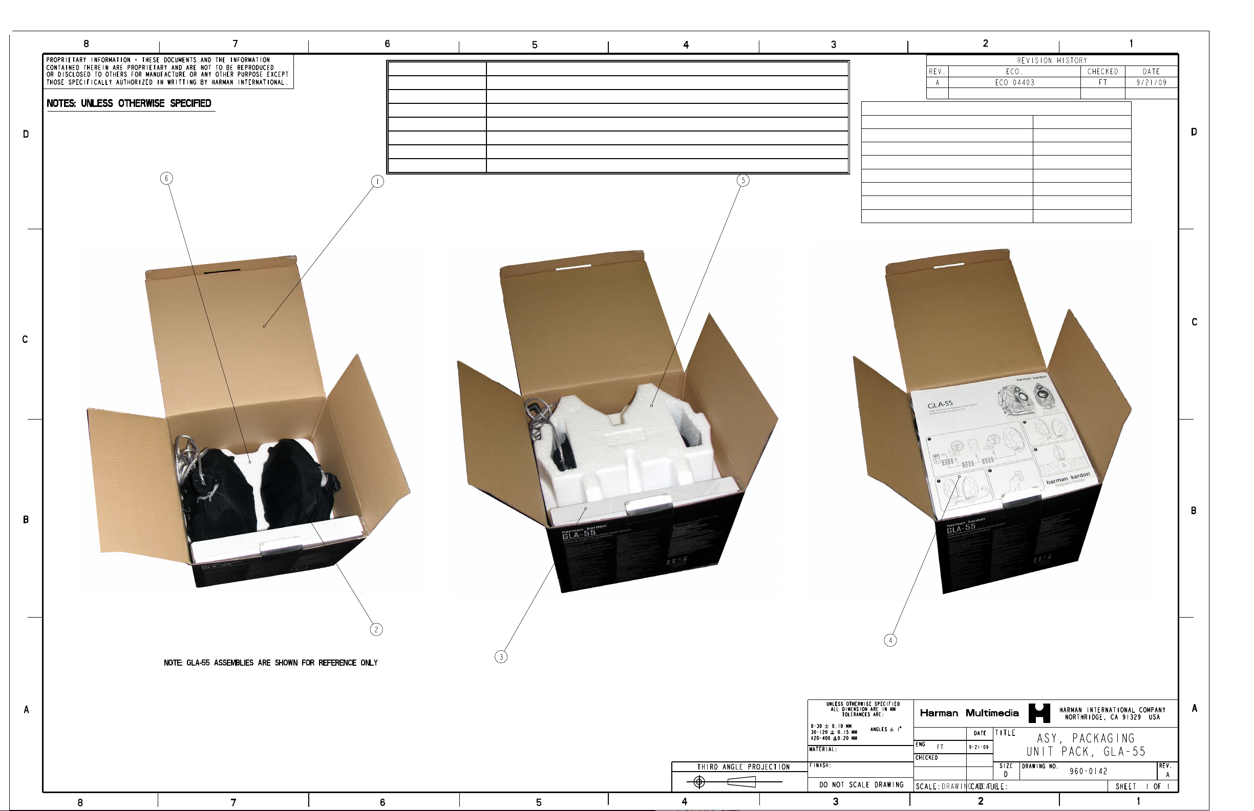
Part Number Description
3
900-0478-001 GIFT BOX, HK CRYSTAL
950-0084-002 WARRANTY CARD; GENERIC HARMAN MULTIMEDIA
905-0032-001 FOAM, CUSHION, TOP, EPE, HK CRYSTAL
905-0033-001 FOAM, CUSHION, BOTTOM, EPE, HK CRYSTAL
500-0368-001 CABLE, STEREO, 3.5MM, STRAIGHT ON ONE SIDE, RT ANGLE
700-0072-001 POWER SUPPLY, HK CRYSTAL, US
AC SUPPLY CORD NEEDED WITH 700-0072-001
AC PWR CORD US 500-0130-001
AC PWR CORD EU 500-0130-002
AC PWR CORD, UK 500-0130-003
AC PWR CORD AUSTRALIA 500-0130-004
AC PWR CORD 100V JAPAN 500-0130-005
AC PWR CORD, KOREA 500-0130-006
AC PWR CORD, CHINA 500-0130-007
Page 5
GLA-55 harman/kardon
4
Page 6

GLA-55 harman/kardon
5
harman/kardon GLA-55
• LED’s and Auto-ON feature:
The unit has an Auto-ON/Standby feature (like many of our other home
subwoofers)
The indicator is a white LED at the front of each loudspeaker
LED operation:
• Steady ON when the unit is powered up and receiving a signal (playing).
• LED’s slowly blink: STANDBY mode. (After approx.10 minutes of no signal)
• Mute function (press both volume buttons same time) the LED will be OFF. In
this state the speaker will not respond to an incoming signal (will not play
again unless it’s unmuted).
• Volume buttons/mute function (touch switch + and – buttons) in the MASTER
speaker above the woofer.
• The optional sub out jack is a 3.5mm stereo plug; this is a full range signal (not
low freq only, but intended only to be connected to powered subwoofers.)
• There is no main AC power switch
Page 7
GLA-55 harman/kardon
6
Page 8
GLA-55 harman/kardon
7
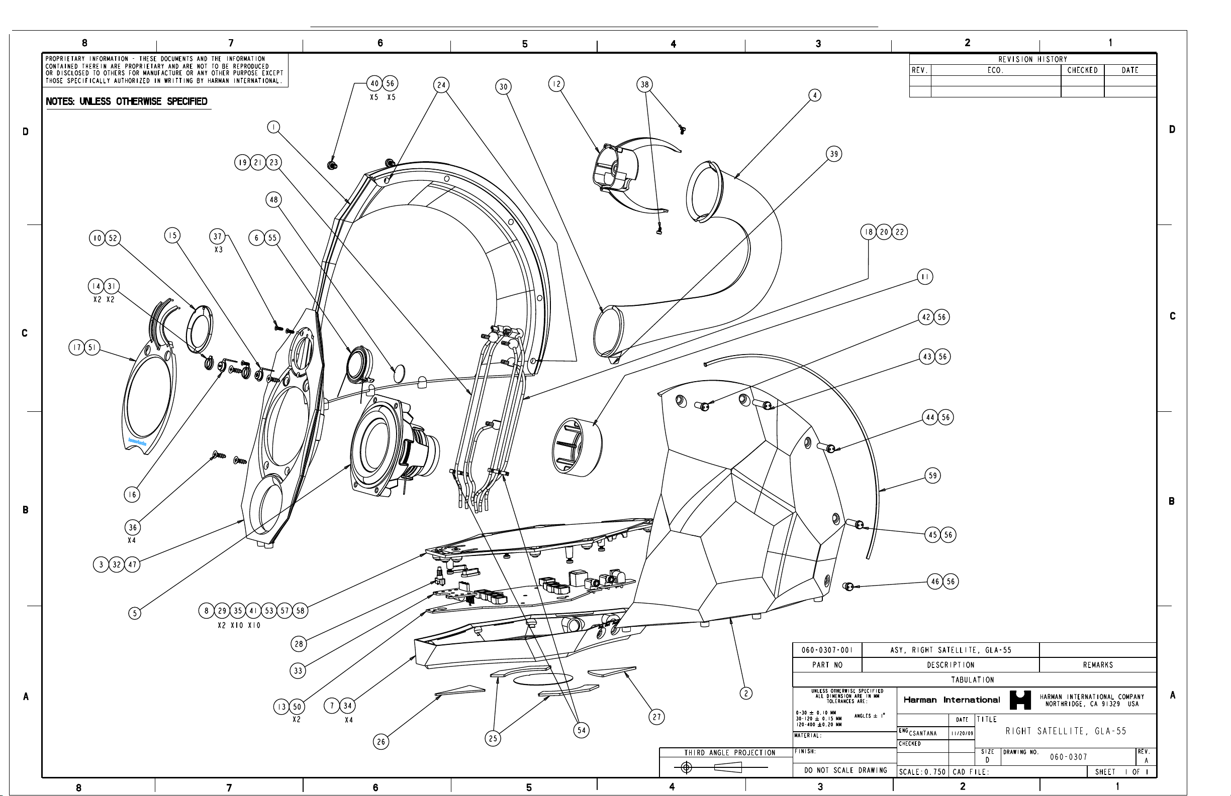
GLA-55 PARTS LIST (RIGHT, ACTIVE) LOUDSPEAKER
Item # Part Number Description Qty
1 100-0092-001 HOUSING, LEFT SIDE, 1 EA
2 100-0093-001 HOUSING, RIGHT SIDE, 1 EA
120-0091-001 BAFFLE, RIGHT, HK GLA-55
3
4 060-0308-001 ASY, PORT, 1 EA
5 050-0168-003B WOOFER, HERCULES ALUMINUM, 4 OHM, COSMETIC, 1 EA
6 050-0132-003B TWEETER, CMMD LITE, 4 OHM, COSMETIC, 1 EA
250-0155-001 BASE ENCLOSURE RIGHT, HK GLA-55
7
250-0154-001 COVER, BASE ENCLOSURE RIGHT, HK GLA-55
8
10 190-0376-001 TRIM, TWEETER, 1 EA
11 190-0528-001 COVER, HERCULES, 1 EA
12 250-0143-001 COVER, CMMD TWEETER, ZINC, 1 EA
13 400-0190-001 PCBA, MAIN, RIGHT SATELLITE, 1 EA
190-0377-001 TRIM, VOLUME BUTTON, HK CRYSTAL
14
190-0378-002 VOLUME BUTTON, PLUS, CHROME, HK CRYSTAL
15
190-0379-002 VOLUME BUTTON, MINUS, CHROME, HK CRYSTAL
16
250-0227-001 BEZEL, HERCULES, RIGHT,ZINC, HK GLA-55
17
18 500-0312-001 ASY, CABLE, VOLUME, PLUS, RIGHT, CHROME, 1 EA
19 500-0313-001 ASY, CABLE, VOLUME, MINUS, RIGHT, CHROME, 1 EA
20 500-0314-001 ASY, CABLE, TWEETER, PLUS, RIGHT, CHROME 1 EA
21
500-0315-001 ASY, CABLE, TWEETER, MINUS, RIGHT, CHROME 1 EA
22
500-0316-001 ASY, CABLE, HERCULES, TOP, CHROME 1 EA
23
500-0317-001 ASY, CABLE, HERCULES, BOTTOM, CHROME 1 EA
24
830-0030-001 WASHER, RUBBER, 1.2MMTHICK 2 EA
25 180-0068-001 FOOT, SIDE, 2.0MM THICK, PMS COOL GRAY 11, 2 EA
26 180-0069-001 FOOT, FRONT, 1.5MM THICK, COLOR: PMS COOL GRAY 11, 1 EA
27 180-0070-001 FOOT, REAR, 2.0MM THICK, COLOR: PMS COOL GRAY 11, 1 EA
190-0380-001 LIGHT PIPE, RIGHT SPEAKER, HK GLA-55
28
190-0533-001 GROMMET,3HOLES,RIGHT SPEAKER,HK GLA-55!
29
30 190-0554-001 SEAL, PORT TO BAFFLE, 1 EA
31 190-0558-001 SEAL, RUBBER, VOLUME BUTTON TO BAFFLE, RIGHT 2 EA
32 190-0558-001 SEAL, RUBBER PAD, BAFFLE TO HOUSING, 1 EA
400-0263-001 PCB, DAUGHTER, HK GLA-55, RIGHT SAT
33
34 800-0048-001 SCREW, MACHINE, M3 X 10MM, PAN HEAD PHILLIPS, ZINC 4 EA
35 800-0048-009 SCREW, MACHINE, M3 X 5MM, PAN HEAD PHILLIPS, ZINC 3 EA
36 800-0149-001
37 800-0150-001
38 800-0151-003
39 800-0152-003
40 800-0155-003
41 800-0156-001
42 820-0016-001
43 820-0016-002
44 820-0016-003
45 820-0016-004
46 820-0016-005
SCREW, FLAT HEAD, SELF TAPPING, BRIGHT ZINC PLATE,
4MMX12MM
SCREW, MACHINE, M2.5 X 7.,5MM, FLAT HEAD, PHILLIPS DRIVE,
ZINC
SCREW, MACHINE, M2.5 X 4.0 MM LONG, SOCKET HEAD CAP,
STEEL, BRIGHT NICKEL PLATE
SCREW, LG PAN HEAD, SELF TAPPING, BRIGHT ZINC PLATE, TORX
DRIVE,TWO START, 3MM DIA. X 8MM LONG
SCREW, MACHINE, M4 X 7MM, CAP HEAD SPANNER, STEEL,
BRIGHT CHROME PLATE
SCREW, MACHINE, M3X6MM LONG, PAN HEAD, PHILLIPS, SPRING
LOCK WASHER, ZINC
BOLT, MACHINE, M4 X 10.00 INTERNAL THREAD, CAP HEAD
SPANNER, STEEL, BRIGHT CHROME PLATE
BOLT, MACHINE, M4 X 22.70 INTERNAL THREAD, CAP HEAD
SPANNER, STEEL, BRIGHT CHROME PLATE
BOLT, MACHINE, M4 X 21.00 INTERNAL THREAD, CAP HEAD
SPANNER, STEEL, BRIGHT CHROME PLATE
BOLT, MACHINE, M4 X 20.30 INTERNAL THREAD, CAP HEAD
SPANNER, STEEL, BRIGHT CHROME PLATE
BOLT, MACHINE, M4 X 7.00 INTERNAL THREAD, CAP HEAD
SPANNER, STEEL, BRIGHT CHROME PLATE
1EA
1EA
1EA
1EA
1EA
1EA
1EA
1EA
2EA
1EA
4EA
3EA
2EA
1EA
4EA
10 EA
1EA
1EA
1EA
1EA
1EA
Page 9

GLA-55 harman/kardon
8
48 850-0075-002 PAD, FOAM, PORON, 18 (D) X 1 (T) 1 EA
50 850-0348-001
51 850-0350-001 PAD, BEZEL, 1 EA
52 850-0351-001 PAD, ADHESIVE, TWEETER COVER, 1 EA
53 850-0352-001 GASKET, COVER BASE, 1 EA
850-0353-001 SPACER, CABLE SUPPORT, CLEAR SILICONE, 3 HOLES, RIGHT
54
55 850-0357-001 GASKET, CMMD TWEETER, 1 EA
56 850-0367-001 RUBBER SEAL, SCREW BOSS, 10 EA
850-0394-001 PAD
57
930-0066-001 INSULATION FILM, PCBA, GLA-55
58
850-0377-001 RUBBER SEAL, GASKET, BTWN HOUSING LEFT,RIGHT,HOUSING
59
PAD, GAP FILLER, HEATSKINK, 11MMX11MMX1MM THICK
2EA
2EA
1EA
1EA
1EA
Page 10

GLA-55 harman/kardon
9
Page 11

A
A
A
A
A
A
(D)
)
GLA-55 harman/kardon
10
GLA-55 PARTS LIST (LEFT, PASSIVE) LOUDSPEAKER
Item # Part Number Description Qty
1 100-0092-001
2 100-0093-001
120-0089-001 BAFFLE, LEFT, HK GLA-55
3
4 060-0308-001
5 050-0168-003B
6 050-0132-003B
7 250-0140-001
8 250-0153-001
10 190-0376-001
11 190-0528-001
12 250-0143-001
14 250-0145-001
16 500-0357-001
17 500-0358-001
18 500-0359-001
19 500-0360-001
20 830-0030-001
25 180-0068-001
26 180-0069-001
27 180-0070-001
28 190-0529-001
29 190-0532-001
30 190-0554-001
31 500-0369-001
32 190-0558-001
33 400-0264-001
34 800-0048-001
35 800-0048-009
36 800-0149-001
37 800-0150-001
38 800-0151-003
39 800-0152-003
40 800-0155-003
41 800-0156-001
42 820-0016-001
43 820-0016-002
44 820-0016-003
45 820-0016-004
46 820-0016-005
48 850-0075-002
51 850-0350-001
52 850-0351-001
53 850-0352-001
54 850-0354-001
55 850-0357-001
56 850-0367-001
850-0377-001 RUBBER SEAL, GASKET, BTWN HOUSING LEFT,RIGHT,HOUSING
59
HOUSING, LEFT SIDE,
HOUSING, RIGHT SIDE,
SY, PORT,
WOOFER, HERCULES ALUMINUM, 4 OHM, COSMETIC,
TWEETER, CMMD LITE, 4 OHM, COSMETIC,
BASE, ENCLOSURE, LEFT, ZINC,
COVER, BASE ENCLOSURE, LEFT,
TRIM, TWEETER,
COVER, HERCULES,
COVER, CMMD TWEETER, ZINC,
BEZEL, HERCULES, LEFT, ZINC,
SY, CABLE, TWEETER, PLUS, LEFT, CHROME,
SY, CABLE, TWEETER, MINUS, LEFT, CHROME,
SY, CABLE, HERCULES, TOP/LEFT, CHROME,
SY, CABLE, HERCULES, BOTTOM LEFT, CHROME,
WASHER, RUBBER, 1.2MMTHICK
FOOT, SIDE, 2.0MM THICK, PMS COOL GRAY 11,
FOOT, FRONT, 1.5MM THICK, COLOR: PMS COOL GRAY 11,
FOOT, REAR, 2.0MM THICK, COLOR: PMS COOL GRAY 11,
LIGHT PIPE, LEFT SPEAKER,
GROMMET, CABLE ISOLATION, 2HOLES, LEFT SPEAKER,
SEAL, PORT TO BAFFLE,
SY, CABLE, INPUT, LEFT, SATELLITE, CLEAR PVC W/METAL BRAID,
SEAL, RUBBER PAD, BAFFLE TO HOUSING,
PCBA, LEFT SATELLITE,
SCREW, MACHINE, M3 X 10MM, PAN HEAD PHILLIPS, ZINC
SCREW, MACHINE, M3 X 5MM, PAN HEAD PHILLIPS, ZINC
SCREW, FLAT HEAD, SELF TAPPING, BRIGHT ZINC PLATE, 4MMX12MM
SCREW, MACHINE, M2.5 X 7.,5MM, FLAT HEAD, PHILLIPS DRIVE, ZINC
SCREW, MACHINE, M2.5 X 4.0 MM LONG, SOCKET HEAD CAP, STEEL, BRIGHT
NICKEL PLATE
SCREW, LG PAN HEAD, SELF TAPPING, BRIGHT ZINC PLATE, TORX
DRIVE,TWO START, 3MM DIA. X 8MM LONG
SCREW, MACHINE, M4 X 7MM, CAP HEAD SPANNER, STEEL, BRIGHT CHROME
PLATE
SCREW, MACHINE, M3X6MM LONG, PAN HEAD, PHILLIPS, SPRING LOCK
WASHER, ZINC
BOLT, MACHINE, M4 X 10.00 INTERNAL THREAD, CAP HEAD SPANNER, STEEL,
BRIGHT CHROME PLATE
BOLT, MACHINE, M4 X 22.70 INTERNAL THREAD, CAP HEAD SPANNER, STEEL,
BRIGHT CHROME PLATE
BOLT, MACHINE, M4 X 21.00 INTERNAL THREAD, CAP HEAD SPANNER, STEEL,
BRIGHT CHROME PLATE
BOLT, MACHINE, M4 X 20.30 INTERNAL THREAD, CAP HEAD SPANNER, STEEL,
BRIGHT CHROME PLATE
BOLT, MACHINE, M4 X 7.00 INTERNAL THREAD, CAP HEAD SPANNER, STEEL,
BRIGHT CHROME PLATE
PAD, FOAM, PORON, 18
PAD, BEZEL,
PAD, ADHESIVE, TWEETER COVER,
GASKET, COVER BASE,
SPACER, CABLE SUPPORT, CLEAR SILICONE, 2 HOLES, LEFT
GASKET, CMMD TWEETER,
RUBBER SEAL, SCREW BOSS,
X 1 (T
1EA
1EA
1EA
1EA
1EA
1EA
1EA
1EA
1EA
1EA
1EA
1EA
1EA
1EA
1EA
1EA
2EA
2EA
1EA
1EA
1EA
2EA
1EA
1EA
1EA
1EA
4EA
3EA
4EA
3EA
2EA
1EA
4EA
10 EA
1EA
1EA
1EA
1EA
1EA
1EA
1EA
1EA
1EA
2EA
1EA
10 EA
1EA
Page 12

GLA-55 harman/kardon
11
GLA-55 disassembly
Tools needed:
• (2) #8 spanner screwdrivers or #8 spanner bits
• Soldering/desoldering tools
• Phillips screwdriver
• Torx (size T10) screwdriver or T10 bit
• Exacto knife
• Optional: One half section of the packing foam
IMPORTANT NOTE:
There a number of pads, gaskets, adhesive, and surfaces with double-sided tape on this
product. Attention must be paid to these areas when the GLA-55 is disassembled. If these
materials are damaged, removed, or disturbed, they must be replaced in their original location,
or the air integrity of the product will be compromised and fidelity may suffer.
I Replacing the Silver-Braided Connecting Cord On The GLA-55 Slave speaker
• Follow steps 1-5 in the procedure below “GLA-55 disassembly Slave speaker (w/ cord)”
II GLA-55 disassembly Left, Slave speaker (w/ cord)
1) Support the loudspeaker with one half section of the packing foam with the base facing upwards.
Alternately, if the packing foam is not available, the speaker must be supported so the base faces
upwards in a clamp so it can be worked on easily, taking care to pad the clamp so the enclosure will not
be scratched.
2) Peel off the four rubber pads on the base cover.
3) Remove the (4) Phillips screws that are now exposed
4) Remove the base cover from the loudspeaker and slide the cord grommet out of the notch
5) Unplug the six pin Molex connector from the small circuit board and set the cord aside.
6) Remove the (3) Torx size T10 screws from the small circuit board
7) There are (4) connections that need to be desoldered (they appear as blobs of solder). Desolder and
remove all excess solder with braided wick or a desoldering tool.
8) Remove the small circuit board; detach and watch for the small, loose “light pipe” that you do not lose it.
9) Remove the (10) Torx size T10 or Phillips screws holding the silver main base on.
10) Remove the single Torx size T10 or Phillips screw (for port tube)
Page 13

GLA-55 harman/kardon
12
11) Remove the (2) black two-hole grommets by sliding them off the conductors; any adhesive present will
need to be removed with an exacto knife.
12) Remove the silver base.
13) Remove the loudspeaker from the packing foam (or clamp); remove the (5) spanner screws holding the
enclosure together. These screws consist of a spanner head threaded post and screw. WARNING
these are all different lengths, and you should mark of keep track of each screw as they are removed.
14) Separate the two enclosure halves, along with the front faceplate.
15) To access the drivers, pull the front chrome bezel off the front baffle; grasp it by the protective bars over
the tweeter dome and pull outward. The bezel is attached to the front baffle with double-sided tape.
16) The woofer screws are now exposed. Remove as needed.
17) Unplug the Faston connectors and buss wire from the woofer terminals.
18) For the tweeter, remove the black trim surrounding the tweeter dome. It can be pried out of the cavity
using a sharp tool at the relief holes at the top of the trim. Remove the (3) screws as needed. CAUTION
the tweeter screws also hold the port tube in place, remove as needed.
19) Unplug the Faston connectors and buss wire from the tweeter terminals.
20) When replacing the woofer, decorative cover part # 190-0528-001 should be ordered and applied to
the woofer magnet with adhesive.
Re-assembly takes place in reverse order, with these tips:
• SEE
• If you have bent the protective bars on the front chrome bezel when removing it, and they will no longer
• (2) black two-hole grommets (#29 on the drawing/parts list) will need adhesive added to seat them, and
IMPORTANT NOTE PAGE 1 OF DISASSEMBLY REGARDING GASKETS
seat in the three holes, the bars may have to be straightened into the correct position again.
to seal the buss wires threading through the holes; use silicon sealer or similar adherent.
III GLA-55 disassembly Right, Master speaker (w/amplifier)
1) Support the loudspeaker with one half section of the packing foam with the base facing upwards.
Alternately, if this packing foam is not available, the speaker must be supported so the base faces up in
a clamp so it can be worked on easily, taking care to pad any tools so the enclosure will not be
scratched.
2) Peel off the four rubber pads on the base cover.
3) Remove the (4) Phillips screws that are now exposed
4) Lift the base cover off the enclosure – warning: lift straight up or you may damage a connector.
5) If needed to replace the Main PCB (amplifier) from the base cover, remove the (7) Phillips screws.
6) Remove the (3) Torx size T10 screws from the small circuit board
Page 14

GLA-55 harman/kardon
13
7) There are (6) connections that need to be desoldered (they appear as blobs of solder). Desolder and
remove all excess solder with braided wick or a desoldering tool.
8) Remove the small circuit board; detach and watch for the small, loose “light pipe” that you do not lose it.
9) Remove the (10) Torx size T10 or Phillips screws holding the silver main base on.
10) Remove the single Torx size T10 or Phillips screw (for port tube)
11) Remove the (2) black three-hole grommets by sliding them off the conductors; any adhesive present
will need to be removed with an exacto knife.
12) Remove the silver base.
13) Remove the loudspeaker from the packing foam (or clamp); remove the (5) spanner screws holding the
enclosure together. These screws consist of a spanner head threaded post and screw. WARNING
these are all different lengths, and you should mark of keep track of each screw as they are removed.
14) Separate the two enclosure halves, along with the front faceplate.
15) To access the drivers, pull the front chrome bezel off the front baffle; grasp it by the protective bars over
the tweeter dome and pull outward. The bezel is attached to the front baffle with double-sided tape.
16) Two of the woofer screws are now exposed. Two more are underneath the volume buttons. Remove
the two Faston connectors from the rear of the buttons, then push the buttons out of the front baffle.
This should expose the two remaining woofer screws; remove as needed.
17) Unplug the Faston connectors and buss wire from the woofer terminals.
18) For the tweeter, remove the black trim surrounding the tweeter dome. It can be pried out of the cavity
using a sharp tool at the relief holes at the top of the trim. Remove the (3) screws as needed. CAUTION
the tweeter screws also hold the port tube in place, remove as needed.
19) Unplug the Faston connectors and buss wire from the tweeter terminals.
20) When replacing the woofer, decorative cover part # 190-0528-001 should be ordered and applied to
the woofer magnet with adhesive.
Re-assembly takes place in reverse order, with these tips:
• SEE
• If you have bent the protective bars on the front chrome bezel when removing it, and they will no longer
• (2) black three-hole grommets (#29 on the drawing/parts list) will need adhesive added to seat them,
IMPORTANT NOTE PAGE 1 OF DISASSEMBLY REGARDING GASKETS
seat in the three holes, the bars may have to be straightened into the correct position again.
and to seal the buss wires threading through the holes; use silicon sealer or similar adherent.
Page 15

GLA-55 harman/kardon
14
Page 16

GLA-55 harman/kardon
15
Page 17

GLA-55 harman/kardon
16
The electronics in the GLA-55 should be
replaced in its entirety with MAIN PCB
part# 400-0190-001. Should this part become
unavailable, the schematic and parts list are
included for reference only. Individual
components are not stocked. For assistance in
obtaining substitutes, contact Harman/kardon
Page 18

GLA-55 harman/kardon
17
PCBA,
RIGHT
SATELLITE,
Assy-PCB
400-0190-001
Part Number Description
Reference
Designator
410-0180-001
603-0001-003
603-0001-004
PCB, MAIN, RIGHT
SATELLITE, GLA-55
RESISTOR, THICK
FILM, 0603, 1/16W,
5%, 1.0K OHM
RESISTOR, THICK
FILM, 0603, 1/16W,
R22, R57, R60, R68,
R69
R19, R20
EA
EA Resistor
EA Resistor
5%, 1.2K OHM
603-0001-006
RESISTOR, THICK
FILM, 0603, 1/16W,
R17
EA Resistor
5%, 2.0K OHM
603-0001-009
RESISTOR, THICK
FILM, 0603, 1/16W,
R16
EA Resistor
5%, 6.8K OHM
603-0001-011
603-0001-018
603-0001-025
RESISTOR, THICK
FILM, 0603, 1/16W,
5%, 10K OHM
RESISTOR, THICK
FILM, 0603, 1/16W,
5%, 100K OHM
RESISTOR, THICK
FILM, 0603, 1/16W,
R15, R29, R42, R43,
R47, R51, R52, R58,
R61, R84, R94
R34, R37, R44, R48,
R77
R64, R76
EA Resistor
EA Resistor
EA Resistor
5%, 4.7K OHM
603-0001-027
603-0001-034
RESISTOR, THICK
FILM, 0603, 1/16W,
5%, 100 OHM
RESISTOR, THICK
FILM, 0603, 1/16W,
R10, R25, R70, R71,
R89, R90
R13, R18, R74, R75
EA Resistor
EA Resistor
5%, 1.0M OHM
603-0001-040
RESISTOR, THICK
FILM, 0603, 1/16W,
R63, R67, R80, R93
EA Resistor
5%, 10 OHM
603-0001-053
RESISTOR, THICK
FILM, 0603, 1/16W,
R56, R59, R73
EA Resistor
5%, 20K OHM
603-0001-054
RESISTOR, THICK
FILM, 0603, 1/16W,
R11
EA Resistor
5%, 33 OHM
603-0001-055
RESISTOR, THICK
FILM, 0603, 1/16W,
R79
EA Resistor
5%, 130K OHM
603-0001-069
RESISTOR, THICK
FILM, 0603, 1/16W,
R83
EA Resistor
5%, 7.5K OHM
603-0001-074
RESISTOR, THICK
FILM, 0603, 1/16W,
R23
EA Resistor
5%, 10M OHM
Page 19

GLA-55 harman/kardon
18
603-0001-077
RESISTOR, THICK
FILM, 0603, 1/16W,
R24
EA Resistor
5%, 1.5M OHM
603-0001-085
RESISTOR, THICK
FILM, 0603, 1/16W,
R91, R92
EA Resistor
5%, 3.0K OHM
603-0001-086
RESISTOR, THICK
FILM, 0603, 1/16W,
R33
EA Resistor
5%, 330 OHM
603-0001-094
RESISTOR, THICK
FILM, 0603, 1/16W,
R27
EA Resistor
5%, 43K OHM
603-0001-098
RESISTOR, THICK
FILM, 0603, 1/16W,
R72
EA Resistor
5%, 13K OHM
603-0005-011
RESISTOR, THICK
FILM, 0603, 1/16W,
R41, R53
EA Resistor
1%, 10.0K OHM
603-0005-039
RESISTOR, THICK
FILM, 0603, 1/16W,
R82
EA Resistor
1%, 24.9K OHM
603-0005-041
RESISTOR, THICK
FILM, 0603, 1/16W,
R14, R28
EA Resistor
1%, 27.4K OHM
603-0005-050
RESISTOR, THICK
FILM, 0603, 1/16W,
R38, R39, R49, R50
EA Resistor
1%, 3.01K OHM
603-0005-093
RESISTOR, THICK
FILM, 0603, 1/16W,
R40, R54
EA Resistor
1%, 12.4K OHM
603-0005-107
RESISTOR, THICK
FILM, 0603, 1/16W,
R85
EA Resistor
1%, 21.5K OHM
603-0005-111
RESISTOR, THICK
FILM, 0603, 1/16W,
R12
EA Resistor
1%, 3.40K OHM
603-0005-131
RESISTOR, THICK
FILM, 0603, 1/16W,
R81
EA Resistor
1%, 8.06K OHM
603-0005-194
RESISTOR, THICK
FILM, 0603, 1/16W,
R35, R36, R45, R46
EA Resistor
1%, 1.54K OHM
603-0005-269
RESISTOR, THICK
FILM, 0603, 1/16W,
R86
EA Resistor
1%, 4.64K OHM
EA Resistor
EA Resistor
603-0015-002
603-0015-004
RESISTOR, THICK
FILM, 1210, 1/4W, 1%,
6.2 OHM
RESISTOR, THICK
FILM, 1210, 1/4W, 1%,
R3, R5-R7, R21,
R26, R87, R88
R1, R2, R8, R9
20 OHM
603-0015-016
RESISTOR, THICK
FILM, 1210, 1/4W, 1%,
R30, R62
EA Resistor
390 OHM
Page 20

GLA-55 harman/kardon
19
603-0015-017
RESISTOR, THICK
FILM, 1210, 1/4W, 1%,
R78
EA Resistor
100 OHM
603-0015-018
RESISTOR, THICK
FILM, 1210, 1/4W, 1%,
R65, R66
EA Resistor
330 OHM
603-0015-019
RESISTOR, THICK
FILM, 1210, 1/4W, 1%,
R4
EA Resistor
750 OHM
603-0015-023
611-0220-001
RESISTOR, THICK
FILM, 1210, 1/4W, 1%,
2.7K OHM
CAPACITOR,
METALLIZED
POLYESTER FILM,
R55
C4, C7, C18, C25,
C98, C105
6030018023
EA Resistor
EA Capacitor
63V, 5%, 1.0UF
612-0004-009
CAPACITOR,
CERAMIC, X7R, 0805,
C29
EA Capacitor
50V, ±10%, 1200PF
612-0004-013
CAPACITOR,
CERAMIC, X7R, 0805,
C49, C56, C63, C77
EA Capacitor
50V, ±10%, 2700PF
612-0004-015
CAPACITOR,
CERAMIC, X7R, 0805,
C40, C47
EA Capacitor
50V, ±10%, 3900PF
612-0004-016
CAPACITOR,
CERAMIC, X7R, 0805,
C48, C62
EA Capacitor
50V, ±10%, 4700PF
612-0004-017
CAPACITOR,
CERAMIC, X7R, 0805,
C53, C74
EA Capacitor
50V, ±10%, 5600PF
612-0004-020
CAPACITOR,
CERAMIC, X7R, 0805,
C85, C96, C131
EA Capacitor
50V, ±10%, 0.01UF
C9, C13, C19, C22,
C24, C27, C30, C34,
C36, C39, C42, C44,
C45, C58-C61, C65-
612-0004-030
CAPACITOR,
CERAMIC, X7R, 0805,
50V, ±10%, 0.1UF
C67, C70-C72, C78C80, C83, C84, C86,
C87, C90, C91, C93,
EA Capacitor
C94, C97, C102C104, C106, C112,
C114, C115, C118C130
612-0004-039
CAPACITOR,
CERAMIC, X7R, 0805,
C89, C92
EA Capacitor
50V, ±10%, 0.039UF
612-0005-004
CAPACITOR,
CERAMIC, NPO,
C33, C38
EA Capacitor
0805, 50V, ±5%, 82 PF
612-0005-006
CAPACITOR,
CERAMIC, NPO,
0805, 50V, ±5%, 220
C35
EA Capacitor
PF
Page 21

GLA-55 harman/kardon
20
EA Capacitor
612-0005-007
CAPACITOR,
CERAMIC, NPO,
0805, 50V, ±5%, 330
C2, C3, C21, C26
PF
EA Capacitor
EA Capacitor
612-0005-035
612-0017-001
CAPACITOR,
CERAMIC, NPO,
0805, 50V, ±5%,
1000PF
CAPACITOR,
CERAMIC, X5R, 1206,
C8, C12, C16, C23,
C28, C32, C52, C54,
C55, C68, C75, C76,
C81, C88, C109
C51, C57, C69, C73
16V, ±10%, 10 UF
612-0018-007
CAPACITOR,
CERAMIC, X7R, 0805,
C111, C113
EA Capacitor
25V, ±10%, .33 UF
EA Capacitor
612-0022-001
CAPACITOR, AL
ELECTROLYTIC,
SMT, CAN, ±20%,
C1, C31, C46
16V, 10UF, SIZE B
612-0022-002
CAPACITOR, AL
ELECTROLYTIC,
SMT, CAN, ±20%,
C117
EA Capacitor
16V, 22UF, SIZE B
EA Capacitor
612-0023-009
CAP, AL
ELECTROLYTIC,
SMT, CAN, ±20%,
C5, C6, C14, C15,
C37, C43
25V, 470UF, SIZE G
EA Capacitor
612-0024-004
CAPACITOR, AL
ELECTROLYTIC,
SMT, CAN, ±20%,
C108
35V, 100UF, SIZE F
612-0041-002
CAPACITOR,
CERAMIC, X5R, 0805,
C95, C99
EA Capacitor
25V, ±20% 2.2 UF
612-0041-003
CAPACITOR,
CERAMIC, X5R, 0805,
C50, C64
EA Capacitor
25V, ±20% 0.47 UF
EA Capacitor
EA Inductors
612-0046-001
620-0012-002
CAPACITOR,
CERAMIC, X7R, 0805,
16V, ±10%, 1 UF
FERRITE BEAD 1206,
600 OHM AT 100MHZ,
0.3 OHM DCR, 500MA
C41, C82, C100,
C101, C107, C110,
C116
FB1, FB2
DC
INDUCTOR, POWER,
MAGNETIC
620-0049-001
SHIELDED, SMT LOW
L1-L8
EA Inductors
PROFILE, 10UH,
MSS1260-103ML
620-0049
INDUCTOR, POWER,
MAGNETIC
SHIELDED, SMT,
COILCRAFT,
Vend Item Ctrl
Dwg
MSS1260 SERIES
630-0011-002
DIODE, 1N4148WS,
SOD323
D2, D3, D6
EA Diodes
Page 22

GLA-55 harman/kardon
21
630-0027-001
DIODE, LM385M3-2.5
ZENER SOT-23
VARISTOR, ESD
D5
EA Diodes
PROTECTION, SMD
630-0034-001
0603, COOPER
SX1-SX16, SX18
EA Diodes
INDSTRIES, ULTRA
LOW IMPEDANCE
630-0042-001
630-0049-001
DIODE, ZENER,
350MW, SOT23, 5.1V
DIODE, SCHOTTKY
RECTIFIER, 40V, 5
AMPS, SB540, DO-
D4
D1
EA Diodes
EA Diodes
201AD
640-0023-001
660-0001-000
660-0002-000
TRIM POT, 3/8 IN,
10K, 3386H-1-103
TRANSISTOR NPN,
2SC2712GR, SMD
TO236MOD
TRANSISTOR PNP,
2SA1162GR,
VR1
Q2, Q3, Q5-Q8, Q11,
Q12
Q1, Q4, Q10
EA Pots/Encdr
EA Transistor
EA Transistor
TO236MOD
660-0006-002
GENERAL
TRANSISTOR, PNP-
Q9
EA Transistor
2N4403, TO-92
660-0041-001
662-0002-004
662-0030-001
MOSFET, P-CH 30V
10A, IRF7416, SO8
COMPARATORS,
LM393, DUAL, S0IC-8
VOLTAGE
REGULATOR TI,
UA78M33CDCY, 3.3V,
M3
U1
U8
EA Transistor
EA AnalogDevice
EA AnalogDevice
500MA, SOT223
EA AnalogDevice
662-0047-001
POWER AMPLIFIER,
QUAD HALF BRIDGE
40V 3.5A, ST518,
U5, U6
PSSO36 (SLUG UP)
670-0016-001
AMPLIFIER, DUAL
OPERATIONAL,
U3, U4
EA Op-Amps
BA4560, SMT
675-0050-001
PROGRAM, CPU, 8
BIT, FREESCALE
MC9SO8GQ8CDTE,
U2
EA Microprocessor
TSSOP16, GLA-55
EA Microprocessor
675-0016-001
CPU, 8 BIT,
MC9S08QG8,
FREESCALE,
TSSOP16
680-0010-001
ADC 24BIT 96KHZ,
AKM AK5358
U9
EA DSP
TSSOP16
DSP,
MULTICHANNEL
680-0012-001
DIGITAL AUDIO
U7
EA DSP
PROCESSOR,
STA308A, TQFP64
Page 23

GLA-55 harman/kardon
22
685-0030-001
LED, SMD, 0603,
WHITE, BRIGHTEK
LED1
EA LEDs
S1A1608W1CA-2A-91
CRYSTAL, OSC,
12.288MHZ,
690-0015-001
ABRACON ASV-
Y1
EA Crystals
12.288MHZ-E-J-S-T,
SMD
AUDIO JACK,
STEREO, 3.5MM, MK
730-0023-000
MININJACK/LGY6502-
J4, J5
EA Connector
0600, BAI CHUAN
HE/PJ314, BLACK
730-0151-002
730-0160-002
CONNECTOR, DIN 6
PIN RIGHT ANGLE
HEADER, NO
SHROUD, 0.1" PITCH,
J1
J6
EA Connector
EA Connector
3 PIN
730-0206-001
730-0215-001
DC POWER JACK,
50V, 3A, ESTD-008
HEADER, NO
SHROUD, 0.1" PITCH
J3
J7
EA Connector
EA Connector
DUAL ROW 6 PIN
730-0228-001
TEST POINT,
THROUGH HOLE
MINIATURE, 0.040"
TP1-TP6
EA Connector
HOLE 0.1" GRID
CONNECTOR,
SAMTEC TSW, 0.1
730-0243-001
GRID, .025 PIN, 0.1
J2
EA Connector
TAIL, .320 LONG, 6
PIN, TSW-106-14-F-S
Page 24

GLA-55 harman/kardon
23
Page 25

5
24
Low- Power Down
AudioDet
C101
C101
1.0u
1.0u
X7R
X7R
25V
25V
High - Power On
X7R
X7R
25V
25V
C40
C40
3900p
3900p
AGND
C105
C105
1.0u
1.0u
Film
Film
50V
50V
5mm
5mm
R67 10R67 10
C47
C47
3900p
3900p
C99
C99
2.2u
2.2u
X5R
X5R
16V
16V
AGND
PWRDN
C104
C104
0.1u
0.1u
AGND
AGND
R59
R59
20K
20K
C88
SX9
SX9
0603
0603
AGND
inL
inRinRinRinR
AGND
C88
1000p
1000p
NPO
NPO
SX7
SX7
0603ESDA
0603ESDA
0603
0603
R58
R58
10K
10K
AGND
12-18mA Active
+VPWR
R61
R61
10K
10K
R56
R56
20K
20K
R57
R57
1.0K
1.0K
1.0K
1.0K
R60
R60
R66
R66
330
330
1210
1210
R65
R65
330
330
1210
1210
D4
D4
BZX84C5V1
BZX84C5V1
SOT23
SOT23
AGND
C100
C100
1.0u
1.0u
C103
C103
0.1u
0.1u
AGND
R63 10R63 10
+3_3VA
3-5 mA Active
C81
C81
1000p
1000p
NPO
NPO
D D
AGND AGND
J5
J5
LGY-6502
LGY-6502
3
2
1
AGND
0603ESDA
0603ESDA
C C
+3_3VD
RF Bridge for crossing power plane
+3_3VD
C115
C115
0.1u
0.1u
+3_3VDU
C95
C95
2.2u
2.2u
X5R
X5R
16V
16V
C96
C96
0.01u
0.01u
7mA power down current
73mA all channels running
Low- Power Down
High - Power On
PWRDN
B B
DGND
+3_3VD
C97
C97
0.1u
0.1u
DGND
Reset
DGND
R10
R10
100
100
+3_3VA
C98
C98
1.0u
1.0u
Film
Film
50V
50V
5mm
5mm
AGND
1
2
3
4
5
6
7
8
9
10
11
12
13
14
15
16
Pull up resistors
shown near micro
SDA
SCL
C27
C27
0.1u
0.1u
DGND
U9
AK5358U9AK5358
1
AINR
2
AINL
3
CKS1
4
VCOM
5
AGND
6
VA
7
VD
DGND8SDTO
AGND
Connect AGND and DGND
a short distance from pins 9-16
or use continuous GND plane
C102
C102
0.1u
0.1u
64
MVO/DSD_CLK
TEST_MODE
VDD3_3_1
GND_1
NC
SDI_78/DSD_6
SDI_56/DSD_5
SDI_34/DSD_4
SDI_12/DSD_3
LRCKI/DSD_2
BICKI/DSD_1
VDD3_3_2
GND_2
NC
RESET
PLL_BYPASS
DGND
A A
Notes:
All non-polar capacitors are 0805 50V X7R ±10%
unless otherwise specified
All polar capacitors are Aluminum Electrolytic ±20%
unless otherwise specified
All resistors are 0603 5% unless othewise specified
PLL Filter (pin 21) is
sensitive - guard and
ground well.
5
4
1
INH
VCC
GND2Output
Y1
Y1
ASV-12.288MHZ-E-J-S-T
ASV-12.288MHZ-E-J-S-T
DGND
5x7mm
5x7mm
Place R
close to
oscillator
16
CKS0
15
CKS2
DIF
PDN
SCLK
MCLK
LRCK
Reset
C93
C93
0.1u
0.1u
NC61NC62NC
60
GND_7
58
59
VDD3_3_7
+3_3VD
SDO_1257SDO_34
C35
C35
220p
220p
NPO
NPO
+3_3VD
DGND
63
PWDM
SA17SDA18SCL19XTI20PLL_FILTER21NC22GNDA_PLL23VDDA3_3_PLL24CKOUT25NC26GND_327VDD3_3_328NC29OUT8_A30NC31OUT7_A
R12
R12
3.40K
3.40K
1%
1%
C29
C29
1200p
1200p
14
13
12
11
10
9
DGNDAGND
DGND
56
55
LRCKO
+3_3VD
BICKO
C90
C90
0.1u
0.1u
54
NC
DGND
53
C91
C91
0.1u
0.1u
GND_6
DGND
52
51
EAPD
VDD3_3_6
50
OUT1_B49OUT1_A
VDD3_3_5
VDD3_3_4
32
C36
C36
0.1u
0.1u
4
4
3
R1133R11
33
+3_3VA
Left-Twt-A
Left-Twt-B
OUT2_A
OUT2_B
NC
GND_5
OUT3_A
NC
OUT4_A
NC
OUT5_A
OUT5_B
NC
GND_4
OUT6_A
OUT6_B
U7
U7
STA308A
STA308A
HZ1206E601R-10
HZ1206E601R-10
C117
C117
22u
22u
16V
16V
Case B
Case B
HZ1206E601R-10
HZ1206E601R-10
3
+3_3VD
C22
C22
0.1u
0.1u
DGND DGND
MClock should be routed in one single
short run with minimal branching. Put
R11 at one end of trace.
Label Test Points on Silk Screen
Avoid stubs to Test Points
Do not install for production
TP3
TP3
TEST POINT
TEST POINT
3.072MHz
SCLK
1
TP4
TP4
TEST POINT
TEST POINT
MCLK
1
48
47
46
45
44
43
42
41
40
39
38
37
36
35
34
33
1 2
1 2
1210
1210
FB1
FB1
1210
1210
FB2
FB2
C30
C30
0.1u
0.1u
Left-Woof-A
Left-Woof-B
Right-Twt-A
Right-Twt-B
Right-Woof-A
Right-Woof-B
Left_Sub_Out
Right_Sub_Out
R9310R93
10
DGND
GLA-55 harman/kardon
+3_3VD
Left-Woof-A
C84
C84
0.1u
0.1u
Left-Woof-B
Right-Woof-A
Right-Woof-B
Right-Twt-A
Right-Twt-B
+VPWR
12.288MHz
TP5
TP5
TEST POINT
TEST POINT
LRCLK
1
TP6
TP6
TEST POINT
TEST POINT
+3_3VD
48KHz
SDTO
1
TP2
TP2
TEST POINT
TEST POINT
1
GND
DGND
TP1
TP1
TEST POINT
TEST POINT
TWARN
1
+3_3VD
C86
C86
0.1u
0.1u
DGND
+3_3VD
C87
C87
0.1u
0.1u
DGND
+3_3VD
RF Bridge for crossing power plane
3
+3_3VD
C59
C59
0.1u
0.1u
C71
C71
0.1u
0.1u
R51
R51
10K
10K
Left-Twt-A
Left-Twt-B
+3_3VD
C80
C80
0.1u
0.1u
C66
C66
0.1u
0.1u
DGND
DGND
DGND
DGND
C58 0.1uC58 0.1u
R47 10KR47 10K
C78 0.1uC78 0.1u
C79
C79
0.1u
0.1u
DGND
C83 0.1uC83 0.1u
DGND
R52 10KR52 10K
C61 0.1uC61 0.1u
C60
C60
0.1u
0.1u
DGND
OUTPL
OUTPL
VCC1P
PGND1P
PGND1N
VCC1N
OUTNL
OUTNL
OUTPR
OUTPR
VCC2P
PGND2P
PGND2N
VCC2N
OUTNR
OUTNR
GNDS
P2
OUTPL
OUTPL
VCC1P
PGND1P
PGND1N
VCC1N
OUTNL
OUTNL
OUTPR
OUTPR
VCC2P
PGND2P
PGND2N
VCC2N
OUTNR
OUTNR
GNDS
P2
18
NC
17
16
15
14
13
12
11
10
9
8
7
6
5
4
3
2
1
18
NC
17
16
15
14
13
12
11
10
9
8
7
6
5
4
3
2
1
AGND
19
GNDREF
20
GNDR1
21
VREG1
22
VREG1
23
VL
24
CONFIG
25
PWRDN
26
TRI-STATE
27
FAULT
28
TWARN
29
INLA
30
INLB
31
INRA
32
INRB
33
VREG2
34
VREG2
35
VSIG
36
VSIG
U5
STA518U5STA518
DGND
Connect DGND and GNDP2
underneath Power Amp IC's
19
GNDREF
20
GNDR1
21
VREG1
22
VREG1
23
VL
24
CONFIG
25
PWRDN
26
TRI-STATE
27
FAULT
28
TWARN
29
INLA
30
INLB
31
INRA
32
INRB
33
VREG2
34
VREG2
35
VSIG
36
VSIG
U6
STA518U6STA518
DGND
Connect DGND and GNDP2
underneath Power Amp IC's
GNDD GNDA GNDP2
DGND
u4p11
DGND
P2
u4p17
P2
P2
u4p2
P2
2
+VPWR
C6
C6
470u
470u
C82
C82
C65
C65
0.1u
0.1u
P2
C70
C70
0.1u
0.1u
P2
u4p2
C72
C72
0.1u
0.1u
P2
C67
C67
0.1u
0.1u
P2
DGND
P2
1.0u
1.0u
25V
25V
C107
C107
1.0u
1.0u
25V
25V
C110
C110
1.0u
1.0u
25V
25V
C116
C116
1.0u
1.0u
25V
25V
25V
25V
CASE G
CASE G
u4p11
+VPWR
L Tweeter
R Woofer
+VPWR
+VPWR
R Tweeter
MSS1260-103ML
MSS1260-103ML
L2 10uH
L2 10uH
u4p17
C118
C118
R3
R3
0.1u
0.1u
6.2
C7
C7
C18
C18
Film
Film
50V
50V
5mm
5mm
1.0u
1.0u
C25
C25
Film
Film
50V
50V
5mm
5mm
1.0u
1.0u
5mm
5mm
C4
C4
Film
Film
50V
50V
+3_3VD
6.2
1210
1210
C9
0.1uC90.1u
C120
C120
0.1u
0.1u
R21
R21
6.2
6.2
1210
1210
R6
R6
6.2
6.2
1210
1210
C19
C19
0.1u
0.1u
C122
C122
0.1u
0.1u
R26
R26
6.2
6.2
1210
1210
R87
R87
6.2
6.2
1210
1210
C125
C125
0.1u
0.1u
C24
C24
0.1u
0.1u
1210
1210
+3_3VA
R7
R7
6.2
6.2
R88
R88
6.2
6.2
1210
1210
C127
C127
0.1u
0.1u
C13
C13
0.1u
0.1u
R5
R5
6.2
6.2
1210
1210
+VPWR
0.1u
0.1u
C119
C119
0.1u
0.1u
0.1u
0.1u
0.1u
0.1u
+VRAW
C121
C121
C124
C124
P2
C126
C126
0.1u
0.1u
C123
C123
0.1u
0.1u
C129
C129
0.1u
0.1u
C128
C128
0603ESDA
0603ESDA
P2
0603ESDA
0603ESDA
0603ESDA
0603ESDA
0603ESDA
0603ESDA
C23
C23
1000p
1000p
NPO
NPO
1000p
1000p
P2
Vol-Up
Vol-Dn
0603
0603
C12
C12
NPO
NPO
SX4
SX4
0603
0603
SX6
SX6
0603
0603
0603
0603
P2
L Woofer
C3
330pC3330p
1.0u
1.0u
Film
Film
50V
50V
R220R2
5mm
5mm
20
MSS1260-103ML
MSS1260-103ML
L4 10uH
L4 10uH
L6
u4p9u4p9
C15
C15
470u
470u
25V
25V
CASE G
CASE G
C14
C14
470u
470u
25V
25V
CASE G
CASE G
C5
C5
470u
470u
25V
25V
CASE G
CASE G
L6
10uH
10uH
MSS1260-103ML
MSS1260-103ML
C26
C26
330p
330p
R9
R9
1.0u
1.0u
20
20
1210
1210
MSS1260-103ML
MSS1260-103ML
10uH
10uH
L8
L8
MSS1260-103ML
MSS1260-103ML
L7 10uH
L7 10uH
R820R8
20
C21
C21
330p
330p
MSS1260-103ML
MSS1260-103ML
L5 10uH
L5 10uH
L3
L3
10uH
10uH
MSS1260-103ML
MSS1260-103ML
R120R1
20
C2
330pC2330p
L1
L1
10uH
10uH
MSS1260-103ML
MSS1260-103ML
+3_3VDU
+3_3VDU
+3_3VD
+3_3VA
+VPWR
+VRAW
Title
Title
Title
Size Document Number Rev
Size Document Number Rev
Size Document Number Rev
Date: Sheet
Date: Sheet
Date: Sheet
Crystal
Crystal
Crystal
070-0149 V
B
070-0149 V
B
070-0149 V
B
2
SX3
SX3
SX5
SX5
1
J1_P3
C8
C8
NPO
NPO
1000p
1000p
J1_P3
External
connector for
Left Sat
J1
J1
J1_P1
J1_P5
J1_P4
J1_P6
J1_P6
LED_gate
J2_P1
J2_P3
P2
R4
R4
750
750
1210
1210
Internal connector for
Right Sat
13Tuesday, August 11, 2009
13Tuesday, August 11, 2009
13Tuesday, August 11, 2009
C16
C16
1000p
1000p
NPO
NPO
J2_P4
0603
0603
0603ESDA
0603ESDA
SX15
SX15
P2
0603
0603
0603ESDA
0603ESDA
SX14
SX14
J2_P5
J2_P6
SX13
SX13
0603ESDA
0603ESDA
0603
0603
P2
SX12
SX12
0603ESDA
0603ESDA
0603
0603
J2_P7
R55
R55
2.7K
2.7K
1210
1210
of
of
of
J1_P2
+VRAW
P2
1
2
3
4
5
6
7
M-DIN_6-R
M-DIN_6-R
SX2
SX2
0603ESDA
0603ESDA
0603
0603
P2
J1_P1
SX1
SX1
0603ESDA
0603ESDA
0603
0603
6
5
4
3
2
1
J2
J2
TSW-106-14-F-S
TSW-106-14-F-S
SX18
SX18
0603ESDA
0603ESDA
0603
0603
SX16
SX16
0603ESDA
0603ESDA
0603
0603
P2
1
Page 26

5
25
+3_3VDU
5mA
DGND
J7
CON6AJ7CON6A
2x3 0.1" header
Programming Header
Do Not Install
for production
12
34
56
DGND
C46
C46
10u
10u
16V
16V
CASE B
CASE B
D D
SCL
DGND
SDA
Label on Silkscreen
1
SCL
SDA
2
GND
3
J6
CON3J6CON3
Do Not Install for production
Layout - avoid stub to connector.
DGND
C C
18VDC 4A
J3
J3
B B
ESTD-008
ESTD-008
Total current draw should drop to approx 30mA in micro
controlled power down state.
1
2
3
PWRIN
SX10
SX10
0603ESDA
0603ESDA
0603
0603
close to
connector
D1
SB540D1SB540
C32
C32
1000p
1000p
NPO
NPO
AGND DGND
All GNDS common - GND Plane
C108
C108
100u
100u
35V
35V
CASE F
CASE F
P2
C109
C109
1000p
1000p
NPO
NPO
0.33u
0.33u
C111
C111
DGND
A A
GNDD GNDA GNDP2
DGND
AGND
P2
C45
C45
0.1u
0.1u
PWRDN
+3_3VDU
+VRAW
R79
R79
130K
130K
D5
D5
LM385M3-2.5
LM385M3-2.5
2 1
SOT-23
SOT-23
DGND
R20
R20
1.2K
1.2K
1
R64
R64
R76
R76
4.7K
4.7K
4.7K
4.7K
AudioDet
R74
R74
1.0Meg
1.0Meg
32
5mA
R19
R19
1.2K
1.2K
1
M3
M3
IRF7416
IRF7416
SO8
SO8
3
2
1
1
R77
R77
100K
100K
Q7
Q7
2SC2712
2SC2712
TO-236MOD
TO-236MOD
1
PTA5/IRQ/TCLK/RESET
2
PTA4/ACMPO/BKGD/MS
3
VDD
4
VSS
5
PTB7/SCL/EXTAL
6
TPB6/SDA/XTAL
7
PTB5/TPMCH1/SS
8
PTB4/MISO
U2
U2
MC9S08QG8CDTE
MC9S08QG8CDTE
TSSOP16
TSSOP16
LED1
LED1
White
White
0603
0603
LED_gate
32
Q5
Q5
2SC2712
2SC2712
TO-236MOD
TO-236MOD
DGND
C42
C42
0.1u
0.1u
5
6
7
8
4
R75
R75
1.0Meg
1.0Meg
32
Q6
Q6
2SC2712
2SC2712
TO-236MOD
TO-236MOD
DGND
R84
R84
2SC2712
2SC2712
TO-236MOD
TO-236MOD
R83
R83
7.5K
7.5K
DGND
5
4
390
390
R30
R30
1210
1210
+3_3VDU
R23
R23
10meg
10meg
1
R25 100R25 100
Place caps close together
Place near power amps
C43
C43
470u
470u
25V
25V
CASE G
CASE G
P2
C113
C113
0.33u
0.33u
R78
R78
100
100
1210
1210
1
R81
R81
8.06K
8.06K
1%
1%
R82
R82
24.9K
24.9K
DGND
10K
10K
C37
C37
470u
470u
25V
25V
CASE G
CASE G
+VPWR
32
Q8
Q8
4
PTA0/KBIP0/TPMCH0/ADP0/ACMP+
PTA1/KBIP1/ADP1/ACMP-
PTA2/KBIP2/SDA/ADP2
PTA3/KBIP3/SCL/ADP3
PTB0/KBIP4/RXD/ADP4
PTB1/KBIP5/TXD/ADP5
PTB2/KBIP6/SPSCK/ADP6
PTB3/KBIP7/MOSI/ADP7
+VRAW
390
390
R62
R62
1210
1210
R22
R22
R27
R27
43K
43K
32
Q3
Q3
2SC2712
2SC2712
TO-236MOD
TO-236MOD
DGND
DGND
Q9
Q9
2N4403
2N4403
TO92
TO92
Good for 25 mA
1%
1%
C28
C28
1000p
1000p
NPO
NPO
DGND
1
1
C112
C112
0.1u
0.1u
32
DGND
U8
U8
UA78M33
UA78M33
SOT223
SOT223
In
GND
2
+3_3VDU
1.0K
1.0K
Q2
Q2
2SC2712
2SC2712
TO-236MOD
TO-236MOD
+VPWR
3
Out
TAB
4
DGND
PWM
150KHz 50% duty cycle
16
15
14
13
12
11
10
9
R24
R24
1.5Meg
1.5Meg
C41
C41
1.0u
1.0u
X7R
X7R
25V
25V
Left_Sub_Out
Right_Sub_Out
R8010R80
C94
C94
10
0.1u
0.1u
DGND
Vol_PWM
Vol_Up_Micro
RESET
PWRDN
R94
R94
10K
10K
DGND
Bass Control
+3_3VD
+3_3VA
C31
C31
10u
10u
16V
16V
CASE B
CASE B
AGND
3
GLA-55 harman/kardon
R44
R44
100K
100K
C50
C50
0.47u
0.47u
25V
25V
10%
10%
X5R
X5R
D6
D6
1N4148WS
1N4148WS
SOD323
SOD323
C1
C1
10u
10u
16V
16V
CASE B
CASE B
3
C85
C85
0.01u
0.01u
Vol_PWM
R34
R34
100K
100K
Bass_A
3.01K 1%
3.01K 1%
R50
R50
C69
C69
10u
10u
20%
20%
1206
1206
25V
25V
X5R
X5R
3.01K 1%
3.01K 1%
R39
R39
+VRAW
VR1
VR1
+3_3VDU
R85
R85
21.6K
21.6K
1%
1%
R86
R86
4.64K
4.64K
1%
1%
Low- Power Down
High - Power On
DGND
Vol_Dn_Micro
Bass_A
+3_3VDU
Screwdriver
adjust trim pot
3
10K
10K
2
1
ccw
ccw
earth gnd shown because of pot location.
All GNDS are connected
C64
C64
0.47u
0.47u
25V
25V
10%
10%
X5R
X5R
+VPWR
R43
R43
10K
10K
R42
R42
10K
10K
AGND
C57
C57
10u
10u
20%
20%
1206
1206
25V
25V
X5R
X5R
AGND
C77
C77
0.0027u
0.0027u
3.01K 1%
3.01K 1%
R49
R49
C63
C63
0.0027u
0.0027u
10.0K 1%
10.0K 1%
R53
R53
3.01K 1%
3.01K 1%
R38
R38
C49
C49
0.0027u
0.0027u
10.0K 1%
10.0K 1%
R41
R41
AGND
+3_3VDU
C106
C106
0.1u
0.1u
0.0027u
0.0027u
f=20KHz
Q=1.307
AGND
C56
C56
f=20KHz
Q=1.307
AGND
R33
R33
330
330
3
2
BA4560
BA4560
3
2
BA4560
BA4560
D3
D3
1N4148WS
1N4148WS
SOD323
SOD323
+3_3VDU
0.4mA
C130
C130
0.1u
0.1u
+VPWR
U4A
U4A
+
-
+VPWR
U3A
U3A
+
-
R16
R16
R17
R17
DGND
C75
C75
8
1000p
1000p
NPO
NPO
V+
OUT
C76
C76
V-
1000p
1000p
NPO
NPO
4
AGND
12.4K 1%
12.4K 1%
R54
R54
C54
C54
1000p
1000p
8
NPO
NPO
V+
OUT
V-
4
AGND
12.4K 1%
12.4K 1%
R40
R40
6.8K
6.8K
2.0K
2.0K
1
1
C55
C55
1000p
1000p
NPO
NPO
R13
R13
1.0Meg
1.0Meg
AGND
AGND
AGND
AGND
C33
C33
82p
82p
NPO
NPO
C34
C34
0.1u
0.1u
1.54K 1%
1.54K 1%
R46
R46
Vol-Shield
DGND
Q1
Q1
2SA1162GR
2SA1162GR
TO-236MOD
TO-236MOD
R91
R91
3.0K
3.0K
R14
R14
27.4K
27.4K
DGND
1.54K 1%
1.54K 1%
R36
R36
C131
C131
.01u
.01u
3
2
1.54K 1%
1.54K 1%
R45
R45
2
+
-
To J10 pin 4
C62
C62
.0047u
.0047u
C74
C74
.0056u
.0056u
1.54K 1%
1.54K 1%
R35
R35
2
D2
D2
1N4148WS
1N4148WS
SOD323
SOD323
OUT
f=20KHz
Q=.5412
C48
C48
.0047u
.0047u
C53
C53
.0056u
.0056u
1
U1A
U1A
LM393
LM393
SO8
SO8
AGND
f=20KHz
+3_3VDU
U4B
U4B
5
+
6
-
BA4560
BA4560
Q=.5412
AGND
1
R68 1.0KR68 1.0K
C38
C38
82p
R18
R18
0.3mA
R15
R15
10K
10K
+3_3VDU
+VPWR
5
6
BA4560
BA4560
82p
NPO
NPO
1.0Meg
1.0Meg
Vol_Dn_Micro
R72 13KR72 13K
8
V+
7
OUT
V-
C68
C68
1000p
1000p
4
NPO
NPO
AGND
+VPWR
8
U3B
U3B
+
V+
OUT
C52
C52
-
V-
1000p
1000p
NPO
NPO
4
AGND
Title
Title
Title
Size Document Number Rev
Size Document Number Rev
Size Document Number Rev
B
B
B
Date: Sheet
Date: Sheet
Date: Sheet
Q4
Q4
2SA1162GR
2SA1162GR
TO-236MOD
TO-236MOD
R92
R92
3.0K
3.0K
5
+
OUT
6
-
C44
C44
R28
R28
0.1u
0.1u
27.4K
27.4K
DGND
Q10
Q10
2SA1162GR
2SA1162GR
TO-236MOD
TO-236MOD
R73 20KR73 20K
AGND
X5R
X5R
25V
25V
20%
20%
1206
1206
10u
10u
R90
R90
C73
C73
100
100
AGND
R48
R48
100K
100K
5%
5%
C51
C51
10u
10u
20%
20%
1206
1206
25V
25V
X5R
X5R
7
AGND
Crystal
Crystal
Crystal
070-0149 V
070-0149 V
070-0149 V
R89
R89
100
100
AGND
R69 1.0KR69 1.0K
0.3mA
+3_3VDU
R29
R29
10K
10K
7
U1B
U1B
LM393
LM393
SO8
SO8
1
3 2
Q11
Q11
2SC2712
2SC2712
TO-236MOD
TO-236MOD
C89
C89
.039u
.039u
X7R
X7R
AGND
+3_3VA
RF Bridge for crossing power plane
R37
R37
100K
100K
5%
5%
R70
R70
100
100
Vol_Up_Micro
AGND
+VPWR
C114
C114
0.1u
0.1u
2SC2712
2SC2712
TO-236MOD
TO-236MOD
0603ESDA
0603ESDA
C92
C92
.039u
.039u
AGND
1
3 2
Q12
Q12
SX11
SX11
0603
0603
R71
R71
100
100
AGND
+VRAW
SX8
SX8
0603ESDA
0603ESDA
0603
0603
AGND
23Tuesday, August 11, 2009
23Tuesday, August 11, 2009
23Tuesday, August 11, 2009
8
V+
V-
4
DGND
AGNDAGND
1
Vol-Dn
Vol-Up
1mA
U1C
U1C
LM393
LM393
SO8
SO8
AGND
C39
C39
0.1u
0.1u
DGND
J4
J4
3
2
1
LGY-6502
LGY-6502
of
of
of
 Loading...