

Page 1
Thank you for purchasing a Harman Kardon CP 35 Home Theater System. This
FRONT
LEFT
SPEAKER
(White)
SURROUND
BACK
LEFT
SPEAKER
(Brown)
SURROUND
BACK
RIGHT
SPEAKER
(Tan)
CENTER
SPEAKER
(Green)
SUBWOOFER
(Purple)
SURROUND
LEFT
SPEAKER
(Blue)
FRONT
RIGHT
SPEAKER
(Red)
SURROUND
RIGHT
SPEAKER
(Gray)
Quick-Start Guide will help you with a basic system installation. For detailed
information on any step in this Guide, please refer to the pages referenced in
the Owner’s Manual for the AVR 335, which is part of this system. We strongly
recommend that you read all four Owner’s Manuals for complete details on
how to install, configure and operate the AVR 335, DVD 31, HKTS 14 and
HKS 4, as well as for the important safety information they contain. You should
also read the Owner’s Manual for the included RCP 2 system remote.
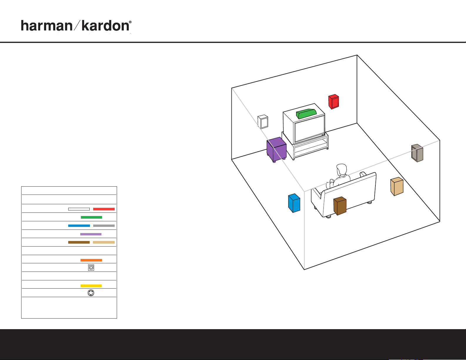
Figure 1 – Speaker Placement
The colors shown for each speaker correspond to
the matching output terminal connection on the back
of the AVR 335 (see page 7).
CP 35 QUICK-START GUIDE
Connections Color Guide
Audio Connections Left Right
Front
Center
Surround
Subwoofer
Surround Back
Digital Audio Connections
Coax
Optical
Video Connections
Composite
S-Video
Match the colored jacks on the AVR 335 to the appropriate
jacks on your source equipment or speakers
standardized, but not all equipment or connectors use them.
The colors are
.
Step 1. Place your speakers in the listening room
(see page 16).
SPEAKER PLACEMENT
Page 2
CP 35 QUICK-START GUIDE
SURROUND BACK
RIGHT SPEAKER
SURROUND BACK
LEFT SPEAKER
FRONT RIGHT
SPEAKER
FRONT LEFT
SPEAKER
CENTER SPEAKER
SUBWOOFER
+
_
LINE LEVEL (LFE)
+
_
SURROUND
RIGHT SPEAKER
+
_
+
_
+
_
SURROUND
LEFT SPEAKER
+
_
+
_
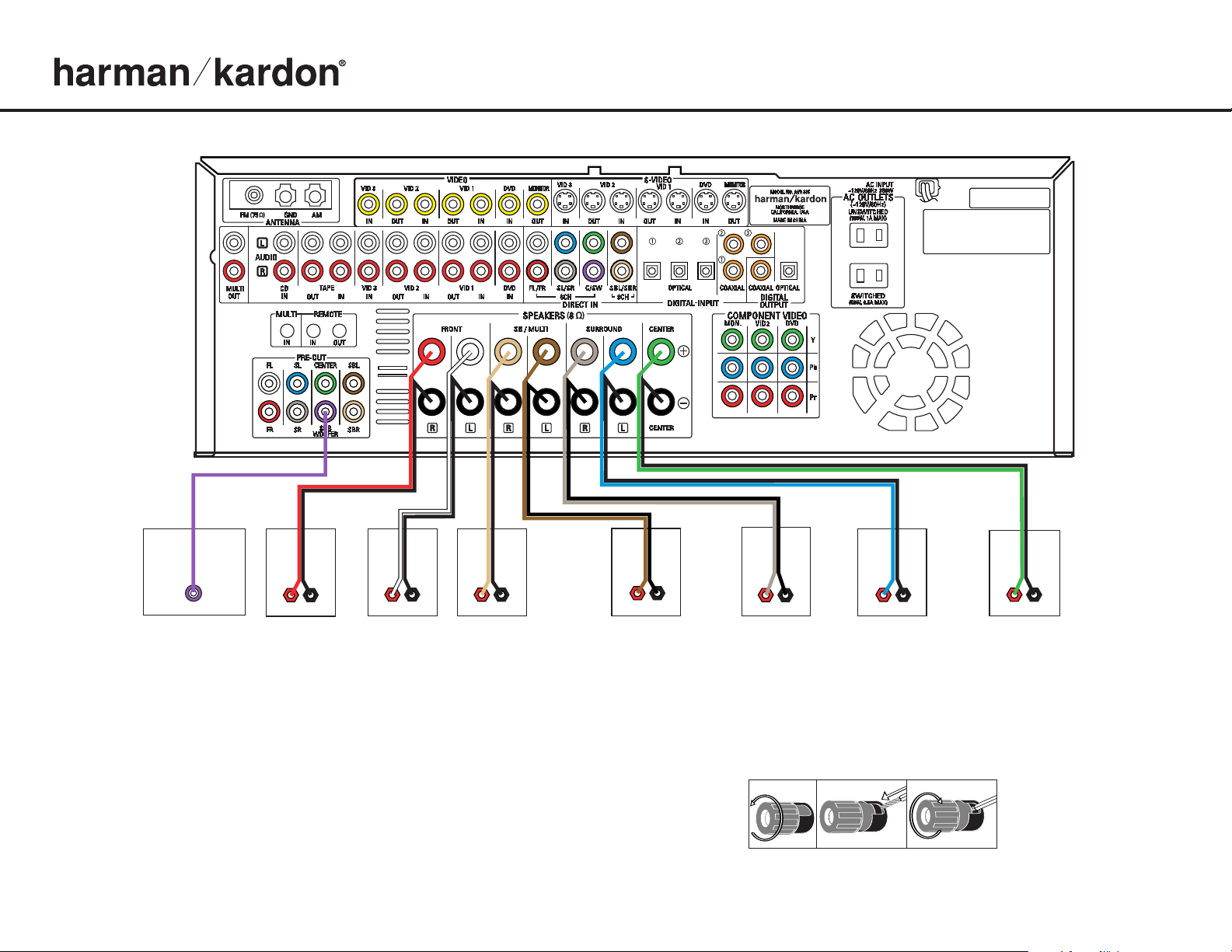
Step 2. Connect the speakers to the receiver: red (+) on speaker to colored (+) on receiver and black
(–) to black (–) (see page 14).
Step 3. Connect the Subwoofer Pre-Out jack to the Line Level In/SUB input jack on your subwoofer.
You may adjust the other settings on the subwoofer later, as needed (see page 14).
Figure 2 – Speaker Connections
Figure 3 – How to Use the Binding-Post
Speaker Terminal
Page 3

A
M Antenna
FM Antenna
240240
91329
/EQ
/EQ
+
Figure 4 – DVD Connections
Dashed lines (––––) indicate coax
and optical digital audio connections.
Choose either type (but not both) for
each digital audio source.
Figure 5 – Connecting EzSet+
Microphone
Step 4. Connect AM and FM antennas, as shown above (see page 14).
Step 5. Connect the DVD 31 to the AVR 335 as shown above:
AUDIO connections: Connect the L/R Audio Out jacks on the DVD
to the L/R DVD Audio in jacks on the AVR.
DIGITAL AUDIO connections: Use the enclosed coaxial interconnect
orange connectors) to connect the Coaxial Digital Output on the
(
DVD to the Coaxial Digital 1 Input on the AVR.
VIDEO connections: Depending on the input available on your TV,
use either composite video (
dotted yellow), S-video (dotted black)
or component video (dotted red/blue/green) connections. Only one
connection type is needed.
POWER: Plug the DVD’s AC power cord into the SWITCHED output
on the back of the AVR. Press the Main Power Switch on the DVD so
that it is ON (see page 17).
Cable or Satellite set-
Connect other source devices such as a
Step 6.
HDTV receiver or audio recorder using the connections
top box,
VCR,
shown in the Device Connection Options chart and Figure 6 on the
back of this Guide. Plug all sources into an AC power outlet.
Step 7. Connect the AVR to your TV or video display. You must make a
composite,“S” or component video connection corresponding
corresponding to each video source device used in your system.
Remember to switch the TV to the correct input for each source.
NOTE: The AVR’s on-screen menus are not available when viewing
a component video connection. For that reason, a composite or
S-video connection is recommended, though not required, when
component video is used.
Basic Configuration
Step 8. Select digital inputs: Use the On-Screen Input Setup menu or the
front-panel Digital Select button and the arrow buttons to select an
optical or coaxial digital input, for any digital source of the DVD
(see page 18).
Step 9.
Use
to configure and optimize your system.
Plug the EzSet+ microphone into the front-panel Headphones
Place the microphone at the center of the room, or
5).
.
Jack (Fig
at your normal listening position. If desired, the mike may be
attached to a standard camera tripod using the threads on the
bottom of the mike. Follow the instructions on pages 20–21 of
the Owner’s Manual, which contains the steps needed to activate
the system. As EzSet+ senses the output of each speaker, you will
hear loud test signals.This is a normal part of the EzSet+ process.
When the on-screen menu indicates that setup is complete, your
system is adjusted for output levels, delay times and speaker settings. Unplug the microphone and store it for future use.
Step 10.
If you are using a component video connection to a digital television,
set the DVD 31’s output to Progressive Scan, as shown on page 17
of the DVD 31 manual.
Step 11.
Your system is configured – sit back and enjoy!
SPEAKER AND DVD CONNECTIONS
Page 4

V
CR (Video 1) TV or Video Monitor
In/Rec
Out/Play
I
N
L
R VIDEO
V
ideo S-Video Component Video
Y
Pb Pr
Component Video
Y Pb Pr
Cable or Sat or HDTV Set-Top Box (Video 2)
O
UT
L R Video S-Video
O
ptical Coax
AUDIO RECORDER
REC/IN
PLAY/OUT
®
Figure 6 – Source Component Connections
Dashed lines (––––) indicate coax and optical digital audio connections. Choose either type (but not both) for each
digital audio source.
Dotted lines (
when available, but you may use any of the three types (but not more than one). When component, composite and
S-video sources are connected to the AVR,you must also connect all outputs from the AVR to your TV.
Device Connection Options: Recommended connections are shown in red, but connections may be made to best fit your system requirements. The Video 4, Coax 3 and Optical 3 inputs are on the front panel of the receiver.
Device Input Name Audio Input Connections Audio Output Connections Video Connections
CD Player CD CD L/R Inputs, Optical Digital 1, 2 or 3, or Coaxial Digital 1, 2 or 3 Not required Not required
DVD Player DVD Coaxial Digital 1, 2 or 3, Optical Digital 1, 2 or 3, or DVD L/R Inputs Not required DVD Component, Composite or S-Video
VCR Video 1 Video 1 L/R Inputs Video 1 L/R Outputs Video 1 Composite or S-Video Input and Output
Cable Box or Satellite Receiver Video 3 Video 3 L/R Inputs, Optical Digital 1/2/3*, or Coaxial Digital 1/2/3* Inputs Not required Video 3 Composite or S-Video Input
Audio Recorder Tape Tape L/R Inputs, Optical Digital 1/2/3** or Coaxial Digital 1/2/3** Inputs Tape L/R Outputs, Digital Optical** or Coaxial Outputs** Not required
TV or Projector Not applicable Not required Not required Monitor-Out Component, Composite and/or S-Video
Check with your cable company to deter
*
mine whether digital audio is available for all channels
It may be necessar
.
y to make BOTH analog and digital connections if it is not.
••••) indicate component, composite or S-vdeo connections. Component video is the preferred connection
Digital audio recorders only
**
.
250 Crossways Park Drive,Woodbury, New York 11797 www.harmankardon.com
© 2004 Harman International Industries, Incorporated Part No. CQE1A235Z
SOURCE COMPONENT CONNECTIONS
 Loading...