

Page 1
harman/kardon
Model
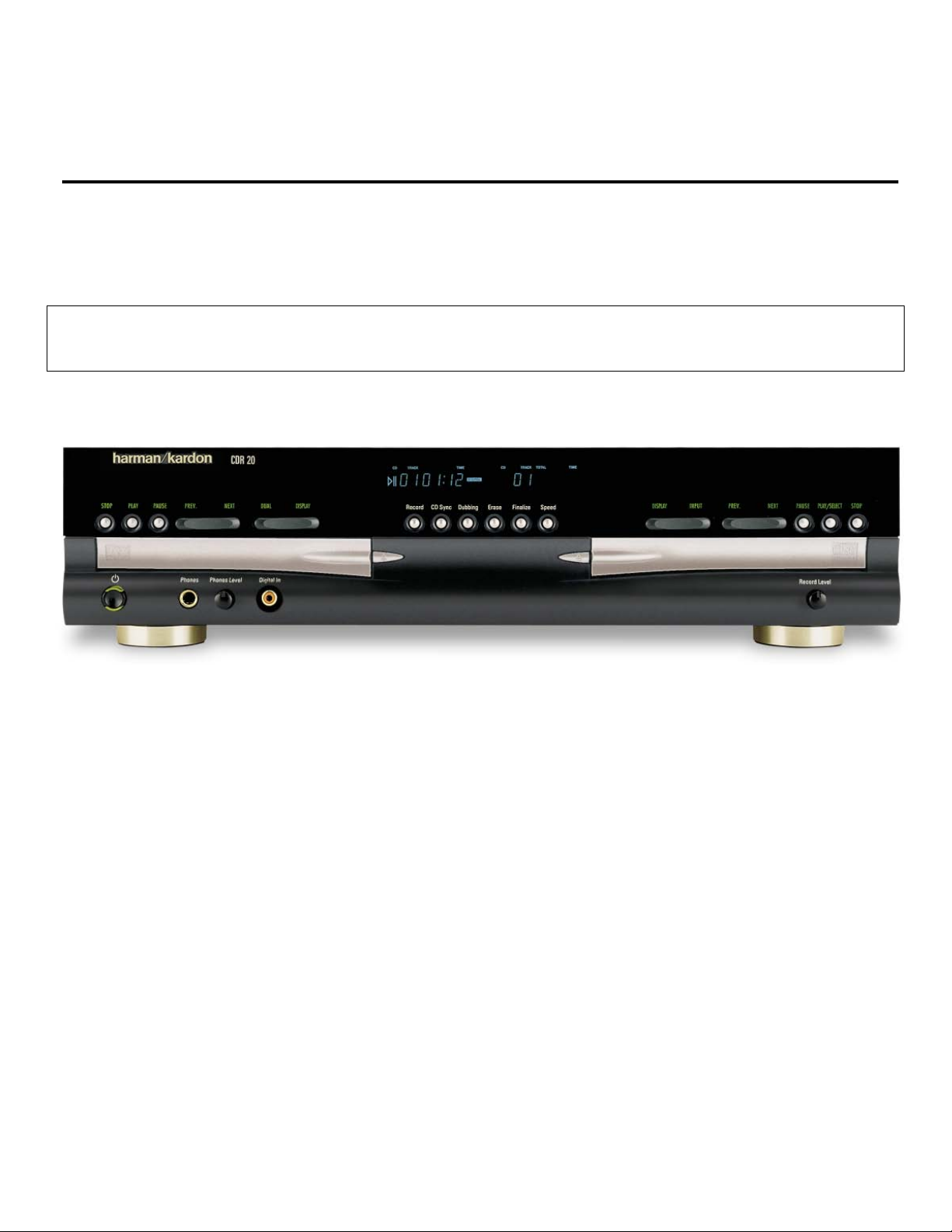
CDR20
Dual Tray CD/CD-R/CD-RW Recorder/Player
SERVICE MANUAL
CONTENTS
SERVICING PRECAUTIONS . . . . . . . . ... . . .. .2
ESD PRECAUTIONS..…………………………... 4
SPECIFICATIONS . . . . . . . . . . . . . . . . . . . .. . . .5
FRONT PANEL CONTROLS ……….. . . .. . . .. . 6
FRONT PANEL DISPLAY ……….. . . .. . . . . . . 8
REAR PANEL CONNECTIONS. . . . . . ……… 10
REMOTE CONTROL FUNCTIONS. . . . . .. .. …11
INSTALLATION/CONNECTIONS. ……………..13
BASIC TROUBLESHOOTING GUIDE………... 14
SPECIAL NOTES ON CDR20 RECORDING… 15
harman/kardon, Inc.
250 Crossways Park Dr.
BULLETIN HK2001-04……………………..……..16
BULLETIN HK2001-06……….. .. . . . . …….. .. . 17
DETAILED TROUBLESHOOTING GUIDE …….19
BLOCK DIAGRAMS . . . . . . . . .. . . .. . .. .. . . . .36
EXPLODED VIEWS . . . . . . . . . . . .. . .. . .. . . . . 39
MECHANICAL PARTS LIST……….. .. . . . . . .. . 42
ELECTRICAL PARTS LIST . . . . . .. . . ..… …….44
PCB DRAWINGS. . . . . . . . . . . . ….. . .. . . . .. . . 65
SCHEMATIC DIAGRAMS . . . . . ……………….. 71
WIRING DIAGRAM………………………………..85
Woodbury, New York 11797
Page 2
2
CDR20
SERVICING PRECAUTIONS
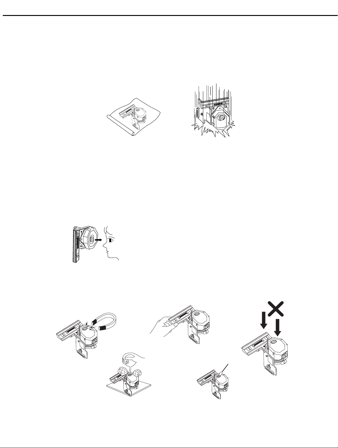
NOTES REGARDING HANDLING OF THE PICK-UP
1. Notes for transport and storage
1) The pick-up should always be left in its conductive bag until immediately prior to use.
2) The pick-up should never be subjected to external pressure or impact.
harman/kardon
Storage in conductive bag
Drop impact
2. Repair notes
1) The pick-up incorporates a strong magnet, and so should never be brought close to magnetic materials.
2) The pick-up should always be handled correctly and carefully, taking care to avoid external pressure and
impact. If it is subjected to strong pressure or impact, the result may be an operational malfunction
and/or damage to the printed-circuit board.
3) Each and every pick-up is already individually adjusted to a high degree of precision, and for that reason
the adjustment point and installation
screws should absolutely never be touched.
4) Laser beams may damage the eyes!
Absolutely never permit laser beams to enter the eyes!
Also NEVER switch ON the power to the laser output part (lens, etc.) of the pick-up if it is damaged.
NEVER look directly at the laser beam, and don’t let contact
fingers or other exposed skin.
5) Cleaning the lens surface
If there is dust on the lens surface, the dust should be cleaned away by using an air bush (such as used
for camera lens). The lens is held by a delicate spring. When cleaning the lens surface, therefore, a cotton swab should be used, taking care not to distort this.
Pressure
Magnet
Pressure
How to hold the pick-up
Cotton swab
Conductive Sheet
6) Never attempt to disassemble the pick-up.
Spring by excess pressure. If the lens is extremely dirty, apply isopropyl alcohol to the cotton swab. (Do
not use any other liquid cleaners, because they will damage the lens.) Take care not to use too much of
this alcohol on the swab, and do not allow the alcohol to get inside the pick-up.
Page 3
3
CDR20
NOTES REGARDING COMPACT DISC PLAYER REPAIRS
1. Preparations
1) Compact disc players incorporate a great many ICs as well as the pick-up (laser diode). These components are sensitive to, and easily affected by, static electricity. If such static electricity is high voltage,
components can be damaged, and for that reason components should be handled with care.
2) The pick-up is composed of many optical components and other high-precision components. Care must
be taken, therefore, to avoid repair or storage where the temperature of humidity is high, where strong
magnetism is present, or where there is excessive dust.
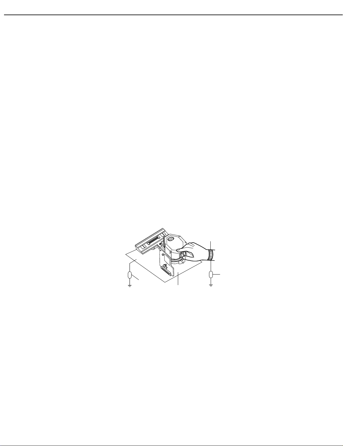
2. Notes for repair
1) Before replacing a component part, first disconnect the power supply lead wire from the unit
2) All equipment, measuring instruments and tools must be grounded.
3) The workbench should be covered with a conductive sheet and grounded.
When removing the laser pick-up from its conductive bag, do not place the pick-up on the bag. (This is
because there is the possibility of damage by static electricity.)
4) To prevent AC leakage, the metal part of the soldering iron should be grounded.
5) Workers should be grounded by an armband (1MΩ)
6) Care should be taken not to permit the laser pick-up to come in contact with clothing, in order to prevent
static electricity changes in the clothing to escape from the armband.
7) The laser beam from the pick-up should NEVER be directly facing the eyes or bare skin.
harman/kardon
Resistor
(1 Mohm)
Armband
Resistor
(1 Mohm)
Conductive
Sheet
Page 4

4
CDR20
harman/kardon
ESD PRECAUTIONS
Electrostatically Sensitive Devices (ESD)
Some semiconductor (solid state) devices can be damaged easily by static electricity. Such components commonly are called Electrostatically Sensitive Devices (ESD). Examples of typical ESD devices are integrated circuits and some field-effect transistors and semiconductor chip components. The following techniques should
be used to help reduce the incidence of component damage caused by static electricity.
1. Immediately before handling any semiconductor component or semiconductor-equipped assembly, drain off
any electrostatic charge on your body by touching a known earth ground. Alternatively, obtain and wear a
commercially available discharging wrist strap device, which should be removed for potential shock reasons
prior to applying power to the unit under test.
2. After removing an electrical assembly equipped with ESD devices, place the assembly on a conductive surface such as aluminum foil, to prevent electrostatic charge buildup or exposure of the assembly.
3. Use only a grounded-tip soldering iron to solder or unsolder ESD devices.
4. Use only an anti-static solder removal device. Some solder removal devices not classified as "anti-static"
can generate electrical charges sufficient to damage ESD devices.
5. Do not use freon-propelled chemicals. These can generate electrical charges sufficient to damage ESD
devices.
6. Do not remove a replacement ESD device from its protective package until immediately before you are
ready to install it. (Most replacement ESD devices are packaged with leads electrically shorted together by
conductive foam, aluminum foil or comparable conductive materials).
7. Immediately before removing the protective material from the leads of a replacement ESD device, touch the
protective material to the chassis or circuit assembly into which the device will by installed.
CAUTION : BE SURE NO POWER IS APPLIED TO THE CHASSIS OR CIRCUIT, AND OBSERVE ALL
OTHER SAFETY PRECAUTIONS.
8. Minimize bodily motions when handing unpackaged replacement ESD devices. (Otherwise harmless motion
such as the brushing together of your clothes fabric or the lifting of your foot from a carpeted floor can generate static electricity sufficient to damage an ESD device).
Page 5

5
CDR20
harman/kardon
CDR20 SPECIFICATIONS
Playback Sampling Frequency 44.1 kHz
D/A Conversion 96kHz, Multi-Bit Delta-Sigma Conversion
Oversampling 128 Times
Playback Specifications
Frequency Response 2Hz – 20,050Hz
Playback S/N 105dB
Playback Dynamic Range 105dB
Playback THD 0.005% / –88dB
Analog Audio Output 2V RMS, ± 2dB
Digital-Coaxial Output 0.5 Vpp/75Ω
Headphone Output 1V RMS/32ΩLoad
Record Specifications
Digital Dubbing Mode(X1/X2/X4) Equal to source
Digital Input Sample Rate 32kHz ~ 96kHz
Signal/Noise Rati o - Analog 91dB
Signal/Noise Rati o - External(Source) source-10dB
Dynamic Range 91dB
THD 0.005%/-85dB
Analog Input Sensitivity 330 mV RMS 47kΩ= 0dB
Digital Inputs (Direct Recording) 44.1kHz, ± 100 ppm/min.
General
Power Requirement 100~240V AC, 50/60Hz
Power Consumption 28 Watts
Dimensions
Height 4.4"/112mm
Width 17.3"/440mm
Depth 14.2"/363mm
Weight 10.5 lb/4.7 kg
Page 6
2
1
3
5
6
7
8
9
)
!
@
#
$
%
^
4
&
*
(
Ó
Ô
Ò
Ú
Û
Ù
ı
ˆ
˜
¯
˘
¸
0
6
CDR20
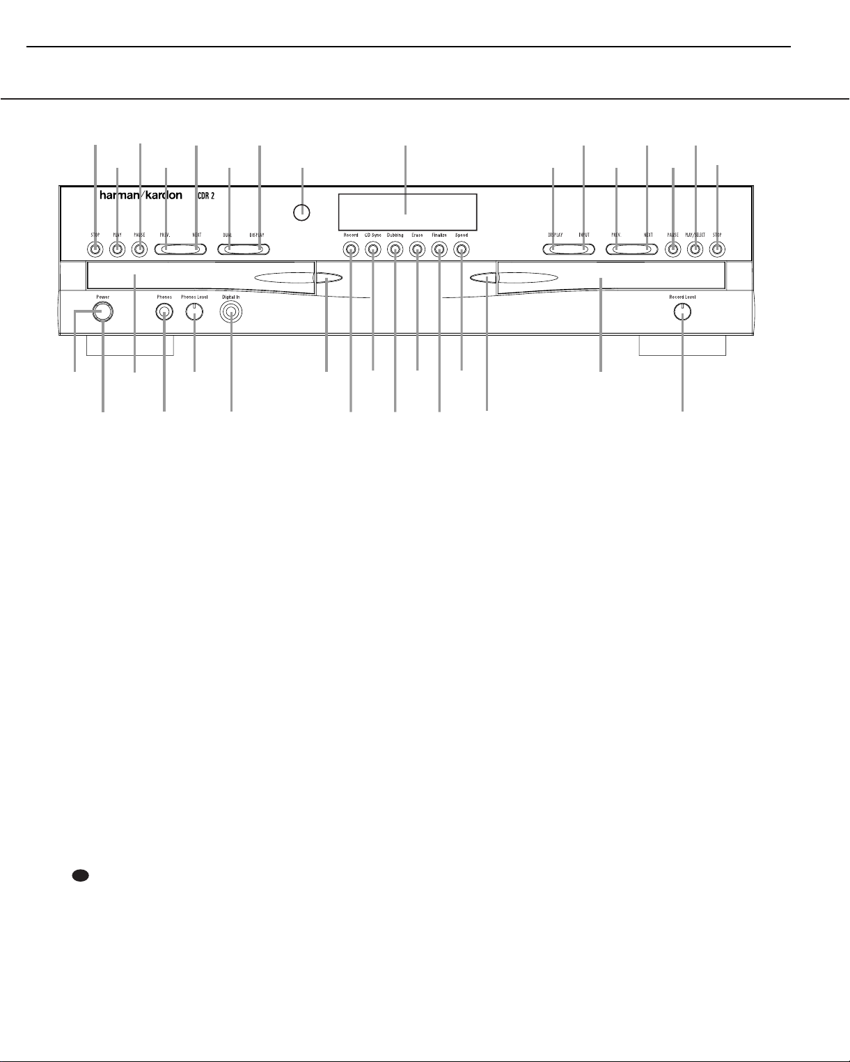
Front-Panel Controls
harman/kardon
1 Power Switch
2 Status-Mode Indicator
3 Play Deck
4 Headphone Jack
5 Headphone Level Control
6 Digital Input
7 Play-Deck Open
8 Record Button
9 CD Sync
) Dubbing
! Erase
1 Power Switch: Press this switch to apply
power to the CDR 20.When the unit is first
turned on, the Status-Mode Indicator 2
surrounding the switch will turn green. Once
the unit has been turned on with this switch, it
may be operated from either the front panel or
remote control. Press the switch again to turn
the unit completely off.
2 Status-Mode Indicator:When the CDR
20 is in the ON mode,this indicator will glow
green.When the unit has been placed in the
Standby mode by pressing the Power-Off but-
ton on the remote,the indicator will glow
amber, indicating that the unit is still connected
to the AC main supply and is ready to be
turned on from the remote control.
3 Play Deck:This disc deck is used to play
back conventional CD discs and CD-R or
CD-RW discs that have been finalized.
32
@ Finalize
# Speed
$ Record-Deck Open
% Record Deck
^ Analog-Record Level Control
& Record-Deck Stop
* Record-Deck Play/Select
( Record-Deck Pause
Ó Record-Deck Next
Ô Record-Deck Previous
Input Select
4 Headphone Jack: Connect standard head-
phones to this jack for private listening.
5 Headphone Level Control: Turn this
control to adjust the volume level to the headphones.Note that the use of this control will
not change the analog output levels at the
rear-panel audio outputs ¡™.
6 Digital Input: This coaxial digital input
may be used to connect a portable digital audio
player to the CDR 20 for digital recording.
When an active digital signal is connected to
both the front- and rear-panel coaxial inputs,
the source connected to the front-panel input
will be selected for recording.
7 Play-Deck Open: Press this button to
open the Play Deck 3.
8 Record Button: Press this button to begin
the recording process.See pages 20-22 for
more information on CD recording.
Ò Record-Deck Display Select
Ú Information Display
Û Remote Sensor
Ù Play-Deck Display Select
ı Dual-Play Selector
ˆ Play-Deck Next
˜ Play-Deck Previous
¯ Play-Deck Pause
˘ Play-Deck Play
¸ Play-Deck Stop
9 CD Sync: Press this button once to begin
an automated recording of a single track from
an external CD player when a digital connection is used. Press it twice to begin automated
recording of an entire disc. See page 21 for
more information on CD Sync recording.
) Dubbing: Press this button to begin the
process of making a complete copy of the disc
in the Play Deck 3 to a CD-R or CD-RW disc
in the Record Deck %. See page 20 for more
information on dubbing.
! Erase: Press this button to erase one or
more tracks or the entire contents of an unfinalized CD-RW disc.When a CD-RW disc has
already been finalized you may erase the entire
disc or you may “unfinalize”the disc by erasing
the TOC data. See page 22 for more information on erasing CD-RW discs.
Page 7

7
CDR20
Front-Panel Controls
harman/kardon
@ Finalize: Press this button when a record-
ing is complete to initiate the finalization
process.The Play/Select Button *j
must be pressed within three seconds to activate finalization.Until this button is pressed
and the finalization process is complete,CD-R
discs may not be played on conventional CD
machines.See page 22 for more information on
finalization.
# Speed: Press this button to select the
recording speed for internal dubs.See page 20
for more information on selecting the proper
speed.
$ Record-Deck Open: Press this button to
open the Record Deck %.
% Record Deck: This Disc Deck is used to
record or play back CD,CD-R and CD-RW discs.
^ Analog-Record Level Control: The con-
trol is used to adjust the input level when making recordings from analog sources such as cassettes,or when CDs are recorded in an analog
mode.See page 22 for more information on
record levels.
& Record-Deck Stop: Press this button to
stop the CD in the Record Deck.
* Record-Deck Play/Select: This button
has two functions.It may be pressed when a
standard CD is in the Record Deck to put the
machine in play,or it may be used to enter a
selection or start certain record functions.
( Record-Deck Pause:When the Record
Deck is in the Play mode,pressing this button
will pause the disc. If the disc has previously
been paused, pressing this button will restart
the playback.
Ó Record-Deck Next: When a disc is play-
ing in the Record Deck %, press and hold this
button to play the disc in a fast-forward mode
to quickly locate a desired passage.At any time,
tapping the button and quickly releasing it will
move to the next track on a disc in play.
Ô Record Deck Previous: This button has
two functions.When a disc is playing in the
Record Deck %, press and hold this button to
play the disc in a fast reverse mode to quickly
locate a desired passage.At any time, tapping
the button and quickly releasing it will move to
the beginning of the current track,and the next
press will move to the previous track.When a
disc is stopped, each press will move back one
for programming or play when the disc is
stopped. Once a track is entered, it may be
played by simply pressing the Play
button *j.
Input Select: Press this button to select
the input source (analog or digital coax) for
recording. See page 22 for more information on
input selection.
Ò Record-Deck Display Select: Press this
button to cycle through the time display options
for the Record Deck. See page 17 for more
information on the time display.
Ú Information Display: The indicators in
the Information Display provide status reports
on the operation of the CDR 20.See page 7 for
complete explanations of each indicator.
Û Remote Sensor: The IR sensor that
receives the commands from the remote control
is behind this area. Do not cover or obscure this
part of the front panel to avoid any malfunction
with the remote.
Ù Play-Deck Display Select: Press this but-
ton to cycle through the time display options
for the Play Deck. See page 17 for more information on the time display.
ı Dual-Play Selector: Press this button to
enable both CD decks to play at the same time
and function as separate,independent CD
units.In this mode it is also possible to record
from an external source while the Play Deck is
functioning as a standard CD player. See page
17 for more information on dual-play capability.
ˆ Play-Deck Next: When a disc is playing in
the Play Deck 3, press and hold this button to
play the disc in a fast-forward mode to quickly
locate a desired passage.At any time, tapping
the button and quickly releasing it will move to
the next track on a disc in play.
˜ Play-Deck Previous: This button has two
functions.When a disc is playing in the Play
Deck 3, press and hold this button to play the
disc in a fast-reverse mode to quickly locate a
desired passage.At any time, tapping the button and quickly releasing it will move to the
beginning of the current track,and the next
press will move to the previous track.When a
disc is stopped, each press will move back one
track for programming or play when the disc is
stopped. Once a track is entered, it may be
played by simply pressing the Play button
˘j.
¯ Play-Deck Pause: When the Play Deck is
running, pressing this button will pause the
disc. If the disc has previously been paused,
pressing this button will restart the playback.
˘ Play-Deck Play: Press this button to begin
playback of a CD in the Play Deck or the dubbing process.
¸ Play-Deck Stop: Press this button to stop
the CD in the Play Deck.
Page 8
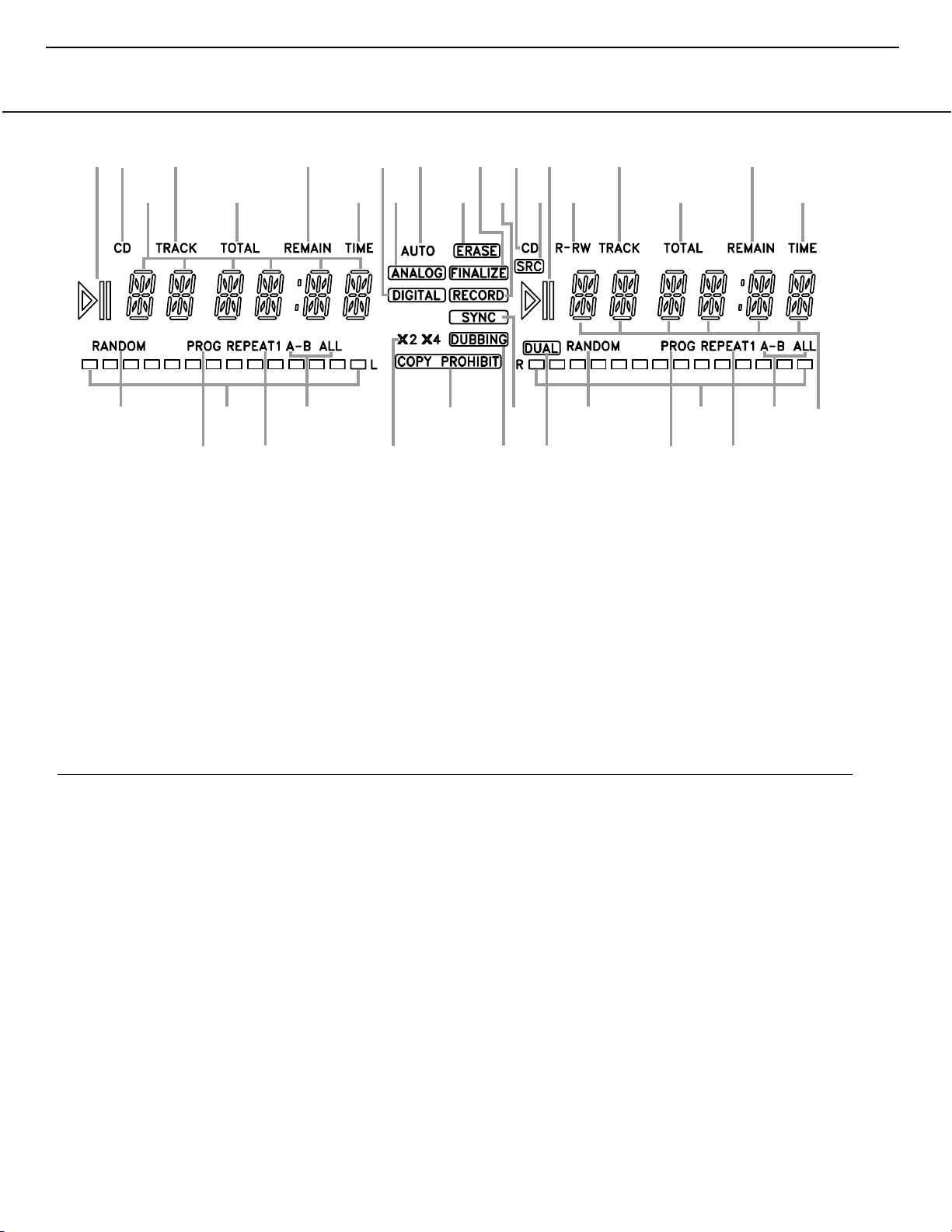
Front-Panel Information Display
A
C
U
W
D
B
E
F
G
I
H
A
J
K
L
M
N
O
L
M
N
O
P
QQ
R
S
S
T
V
X
Y
K
C
D
B
E
A Random Indicators
B Program Indicators
C Level Indicators
D Repeat Indicators
E Repeat-Status Indicators
F Speed Indicators
G Copy-Prohibit Indicator
H Dubbing Indicator
I Sync Indicator
J Dual-Play Indicator
K Information Displays
L Time Indicators
M Remaining-Time Indicators
N Total-Time Indicators
O Track-Time Indicators
P R/RW Indicator
Q Play/Pause Indicators
R Sample-Rate Converter
S CD Indicators
T Record Indicator
U Finalize Indicator
V Erase Indicator
W Auto Indicator
X Analog Indicator
Y Digital Indicator
A Random Indicators: These indicators light
when random playback has been programmed
for one of the CD decks.See page 16 for more
information on random play.
B Program Indicators: These indicators
light when one of the CD decks is being programmed for playback options.See page 18 for
more information on programmed play.
C Level Indicators: These LEDs display the
input level during an analog recording, and the
output level during playback. See page 22 for
more information on record levels.
D Repeat Indicators: These indicators light
when a repeat function is being used. See page
18 for more information on repeat play.
E Repeat-Status Indicators: These indica-
tors display the type of repeat function being
used. See page 18 for more information on
repeat status.
F Speed Indicators: These indicators show
which record speed has been selected for dub
recordings.See page 20 for more information
on record-speed selection.
G Copy-Prohibit Indicator: This indicator
lights when a recording is not possible
due to the intervention of the Serial Copy
Management System (SCMS). See page 20 for
more information on SCMS.
H Dubbing Indicator: This indicator lights
when a dub is in progress between the two CD
Decks.See page 20 for more information on CD
dubbing.
I Sync Indicator: This indicator lights when
the unit has been programmed for a CD Sync
recording. See page 21 for more information on
CD Sync recordings.
J Dual-Play Indicator: This indicator lights
when the unit is playing in the Dual mode,
which allows both CD decks to act as playback
decks at the same time.See page 17 for more
information on the dual-play mode.
K Information Displays: These displays
serve two functions,showing the time displays
for discs playing, and displaying messages
about discs or recordings.
Important Note: Since the CDR 20 is a dual-deck player/recorder,there are two separate sets of indicators for the Random,Program,Repeat,Repeat
Status,Time,Total Time and Track Time.In addition, there is a separate Information Display,Play/Pause Indicator and CD Indicator for each deck. As the
function of these indicators is identical for both decks,they are described in this manual with a common letter. When the CDR 20 is playing or recording a
disc, any indicators that light on the left side of the display describe the status of the Play Deck, while those that light on the right side of the display
describe the status of the Record Deck. Depending on the activity of the unit and the settings you select, different indicators may light on the two sides at
the same time.
8
CDR20
harman/kardon
Page 9

9
CDR20
Front-Panel Information Display
harman/kardon
L Time Indicators: These indicators light in
conjunction with one of the time indicators
MNO to show which of the time status
modes is active.
M Remaining-Time Indicators: These indica-
tors light when the Information Display K
shows the time remaining on a disc.
N Total Time:These indicators light when the
Information Display K shows the total time of
all tracks on a disc.
O Track Time:These indicators light when the
Information Display K shows the running time
of the individual track being played.
P R/RW Indicator: This indicator shows which
type of recordable disc is present in the Record
Deck %.When a CD-R disc is present,only the
R is lit.The RW lights when an erasable CD-RW
disc is in use.
Q Play/Pause Indicators:These indicators
show the status of the individual CD decks.The
› lights when the CD is playing, and the ›
lights when the unit is in a Pause mode.
±±
R Sample-Rate Converter: This indicator
lights when the Sample-Rate Converter is in use
to change the digital sample rate when the
incoming signal is not the standard 44.1kHz
used by standard CDs.This is an automatic function and does not require any user intervention.
S CD Indicators: These indicators light when
a standard CD is playing in either deck 3 or
%.
T Record Indicator: This indicator lights
when the unit is making a recording and flashes
during the preparations for recording.
U Finalize Indicator: This indicator lights
when the unit is in the Finalization process,
which is required before a CD-R disc may be
played on a standard CD machine.See page 22
for more information on Finalization.
V Erase Indicator: This indicator lights when
a CD-RW disc is being erased.Note that only
CD-RW discs may be erased;it is not possible to
erase a CD-R disc.See page 22 for more information on erasing discs.
W Auto Indicator: This indicator lights when
the automatic method of incrementing tracks is
selected for a recording session. See page 21 for
more information on track increments.
X Analog Indicator: This indicator lights
when an analog source is being recorded.
See page 21 for more information on source
selection.
Y Digital Indicator: This indicator lights when
a digital source is being recorded. See page 21
for more information on source selection.
Page 10
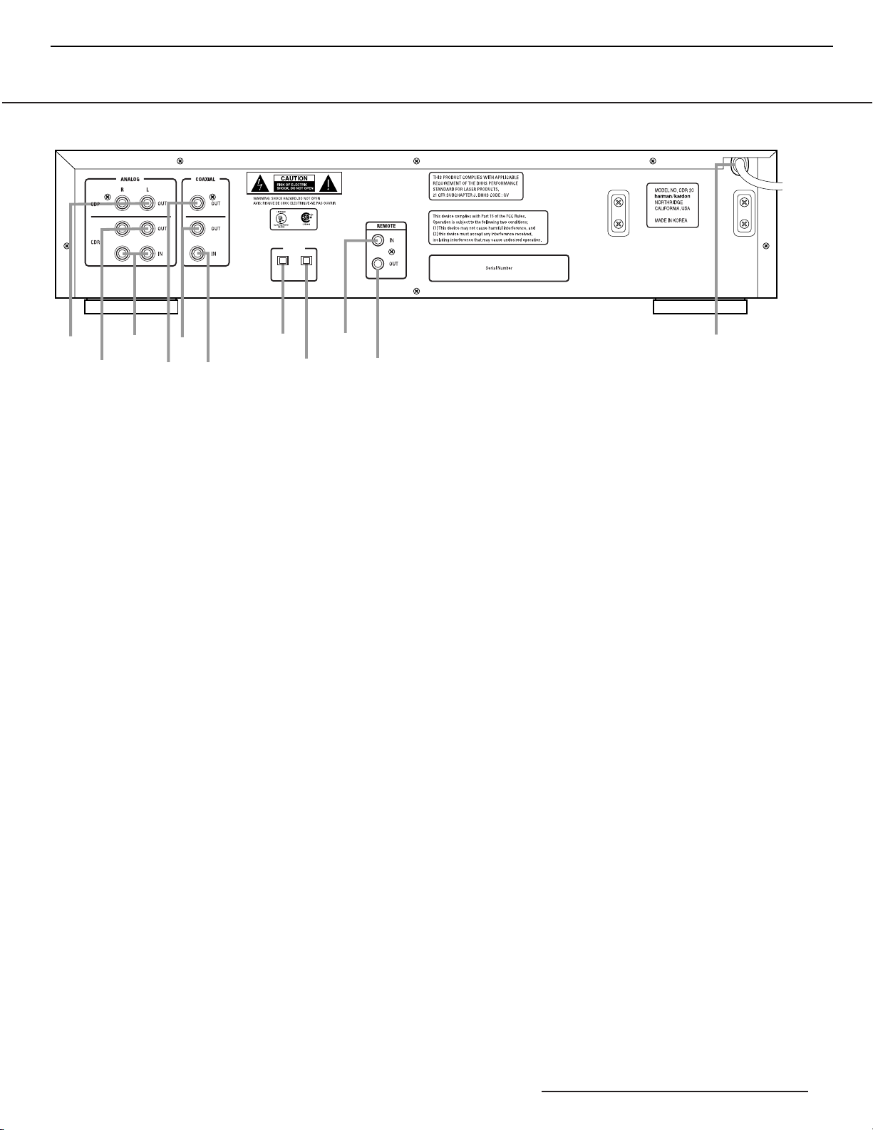
Rear-Panel Connections
¡
™
£
¢
∞
§
⁄
ª
AC 100~240V 50-60Hz 28W
CDR
IN
¶
•
‚
OPTICAL
CDP
OUT
¡ Play Deck (CDP) Analog Output
™ Record Deck (CDR) Analog Output
£ Record Deck (CDR) Analog Input
¢ Play Deck (CDP) Coaxial-Digital Output
∞ Record Deck (CDR) Coaxial-Digital Output
§ Record Deck (CDR) Coaxial-Digital Input
¶ Record Deck (CDR) Optical-Digital Input
• Play Deck (CDP) Optical-Digital Output
ª Remote IR Input
‚ Remote IR Output
⁄ AC Power Cord
¡ Play Deck (CDP) Analog Output: These
jacks carry the analog audio output signal from
the Play Deck 3. Connect them to the CD
input jacks on a receiver, preamp or processor.
™ Record Deck (CDR) Analog Output:
These jacks carry the output signal from the
Record Deck %. Connect them to the Tape
Play/In input jacks on a receiver,preamp or
processor.
£ Record Deck (CDR) Analog Input:These
jacks accept the analog signals that are used
for CD recordings.Connect them to the Tape
Rec/Play outputs on a receiver, preamp or
processor.
¢ Play Deck (CDP) Coaxial-Digital
Output: This jack carries the digital-audio out-
put signal from the Play Deck 3. Connect it
to a coaxial-digital input on a receiver, processor or digital decoder.
∞ Record Deck (CDR) Coaxial-Digital
Output: This jack carries the digital audio out-
put signal from the Record Deck %. Connect
it to a coaxial digital input on a receiver,
processor or digital decoder.
§ Record Deck (CDR) Coaxial-Digital
Input: This jack accepts the digital-audio input
signal from a compatible digital audio product
and should be connected directly to a digital
player or to a coaxial-digital output on a CD or
DVD player or an A/V receiver or processor.
IMPORTANT NOTE: The coaxial digital inputs
should only be connected to digital input or
output jacks.Even though they use the same
RCA type connector as standard analog audio
connections,DO NOT connect them to conventional analog input or output jacks.
¶ Record Deck (CDR) Optical-Digital
Input: This jack accepts the digital-audio input
signal from a compatible digital audio product,
and should be connected to the optical-digital
output on a CD or DVD player or an A/V
receiver or processor.
• Play Deck (CDP) Optical-Digital
Output: This jack carries the optical digital
output signal from the Play Deck 3. Connect
it to an optical digital input on a receiver,
processor or digital recorder. This will typically
be connected to the “CD”input.
ª Remote IR Input: Connect the output of a
remote infrared sensor or the remote control
output of another compatible Harman Kardon
product to this jack.This will enable the remote
control to operate even when the front-panel
Remote Sensor Û is blocked.This jack may
also be used with compatible IR remote control
based automation systems.
‚ Remote IR Output: Connect this jack
to the IR input jack of another compatible
Harman Kardon remote controlled product to
have the built-in remote sensor Û on the
CDR 20 provide IR signals to other compatible
products.
⁄ AC Power Cord: Connect this plug to an
AC outlet.If the outlet is switch controlled,
make certain that it is in the ON position.
10
CDR20
harman/kardon
Page 11
11
CDR20
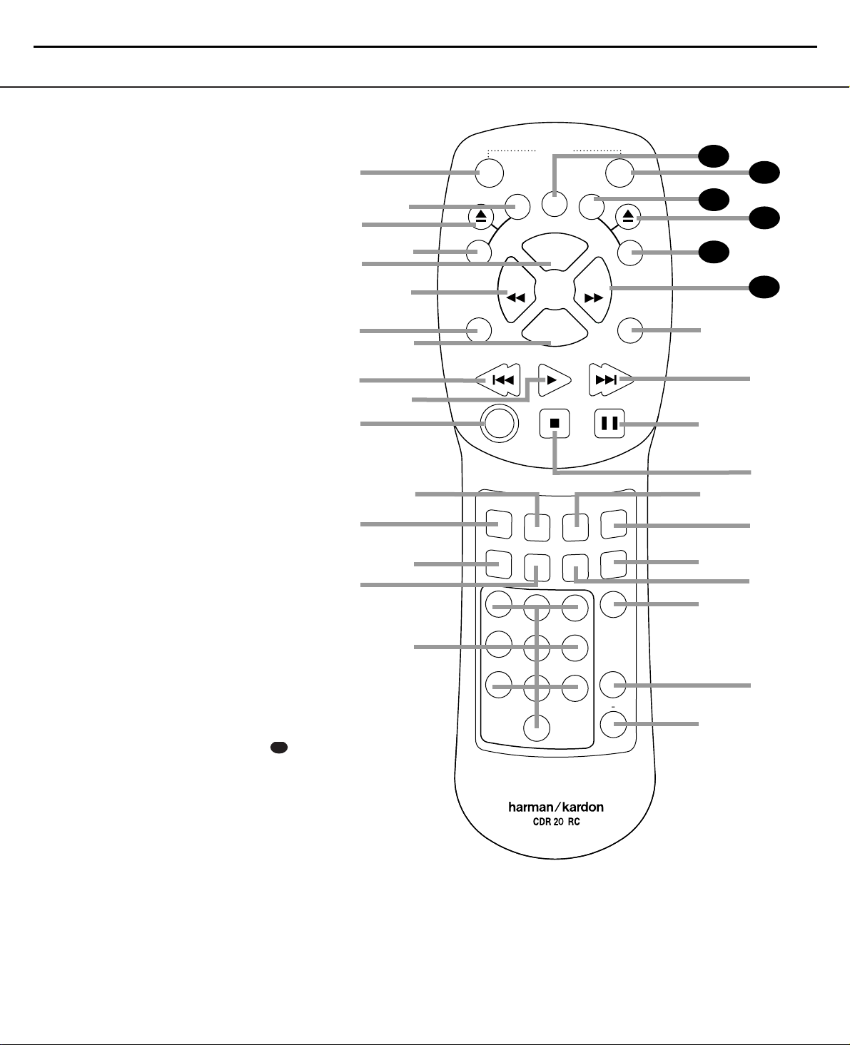
Remote Control Functions
a Power-On Button
b Play Deck (CDP) Display Control
c Play Deck (CDP) Open
d Play Deck (CDP) Select
e Program
f Reverse Search
g Single
h Program Check
i Previous-Track Skip
j Play/Select
k Random Play
l Dub
m Automatic/Manual Track Increment Selector
n Track Increment
o Finalize
p Numeric Keys
q A-B Repeat
r Repeat
s Speed Select
t Record Button
u Erase Button
v Input Select
w CD Sync
x Stop
y Pause
z Next Track/Skip
` Dual-Deck Playback
Forward Search
28
●
Record Deck (CDR) Select
29
●
Record Deck (CDR) Open
30
●
Record Deck (CDR) Display Control
31
●
Power Off
32
●
Clear
33
●
34
IMPORTANT NOTE: Some of the remote’s
functions, including Play,Pause, Stop,
Search, Next and Previous Track, are
shared between the two decks.Always
remember to press the CDP Select button
d to use the remote to control the Play
Deck, or press the CDR Select button
to control the Record Deck. When you
press one of these buttons, an indication
of CDP or CDR will appear in the appropriate Information Display K.
29
a
c
e
g
i
k
m
o
b
d
f
h
j
l
n
p
ON
P
D
C
SINGLE
AUTO/MAN
TR INCR
P
S
I
D
SEARCH
PREV
RANDOM
1
4
7
L
POWER
Y
A
CLEAR
PROG.
PROG
CHECK
PLAY/SELECT
STOP PAUSE
DUB
CD SYNC
FINALIZE
REC
23
6
5
8
9
0
CDR/RW
S
I
D
P
L
SEARCH
NEXT
INPUT
ERASE
SPEED
REPEAT
OFF
A
Y
A B
DUAL
harman/kardon
33
32
31
30
C
D
R
29
28
`
z
y
x
w
v
u
t
s
r
q
Page 12

Remote Control Functions
a Power-On Button: Press this button to
turn the CDR 20 on. Note that in order for this
control to function, the Front-Panel Power
Switch 1 must first be pressed so that the
unit is in the Standby mode.
b Play Deck (CDP) Display Control: Press
this button to cycle through the various time
display options for the disc in the Play Deck
3. See page 17 for more information on time-
display options.
c Play Deck (CDP) Open: Press this button
to open the Play Deck 3.
d Play Deck (CDP) Select: Press this but-
ton to control or program the functions of the
disc in the Play Deck 3.
e Program: Press this button to begin the
programming sequence for one of the CD
decks.See page 18 for more information on
programming the CDR 20.
f Reverse Search: Press this button to play
the selected disc in reverse to locate a desired
passage.
g Single: When this button is pressed, the
CDR 20 will function as a two-disc CD player/
changer. In the Single mode,the audio output
will be routed to all output jacks ¡™¢∞
• regardless of which CD deck is actually
playing. See page 17 for more information on
the Single-Play mode.
h Program Check: Press this button to
check or edit a programmed playback sequence.
See page 18 for more information on programmed
playback.
i Previous-Track Skip: Press this button to
skip backwards to the beginning of the track
currently being played. Press it a second time to
move back to the beginning of each previous
track.
j Play/Select: This button has two func-
tions.It will most often be used as a standard
play button, but when setting up certain record
functions,it is also used as an Enter or Select
button.
k Random Play: When the CD deck is
stopped, press this button to begin random play
of all tracks on a disc.
l Dub: Press this button to begin a dub.See
page 20 for more information on dubbing.
m Automatic/Manual Track Increment
Selector: Press this button to select between
automatic and manual track increments during
a recording session. See page 21 for more information on track increments.
n Track Increment:When the Manual
mode for track increments is selected during
recording, press this button to increase the
track number. NOTE: This function does not
operate during CD Sync or dub recording.
o Finalize: Press this button when a record-
ing is complete to initiate the finalization
process.The Play/Select button *j must
be pressed within three seconds to activate
finalization. Until this button is pressed and the
finalization process is complete,CD-R or CD-RW
discs may not be played on conventional CD
machines.See page 22 for more information
on Finalization.
p Numeric Keys: Press these buttons to
access a specific track for playback or during
the programming process.See page18 for more
information on programmed playback.
q A-B Repeat: Press this button to specify a
segment of a disc for repeat play.See page 18
for more information on repeat play.
r Repeat: Press this button once to repeat
the current track.To repeat an entire disc, press
the button twice.
s Speed Select: Press this button to select
the recording speed for internal dubs.See page
20 for more information on selecting the proper
speed.
t Record Button: Press this button to
begin a manual recording.
u Erase Button: Press this button to initiate
the erasure of a track or of an entire CD-RW
disc or to Unfinalize a disc. Note that erasure is
only possible on CD-RW discs.See page 22 for
more information on erasing discs.
v Input Select: Press this button to select
the input source (analog or digital-coax) for
recording. See page 21 for more information on
input selection.
w CD Sync: Press this button once to begin
an automated recording of a single track from
an external CD player when a digital connection
is used. Press it twice to begin automated
recording of an entire disc. See page 21 for
more information on CD Sync recording.
x Stop: Press this button to stop playback or
recording.
y Pause: Press this button to momentarily
pause playback. Press it again to resume
playback.
z Next Track/Skip: Press this button to skip
forward to the next track on a disc.
` Dual Deck Playback: Press this button
to enable both CD decks to play back at the
same time and function as separate,independent CD units.In this mode it is also possible to
record from an external source while the Play
Deck is functioning as a standard CD player. See
page 17 for more information on dual-play
capability.
Forward Search: Press this button to
play a disc in a fast-forward mode.
Record Deck (CDR) Select: Press this
button to control or program the functions of
the disc in the Record Deck %.
Record Deck (CDR) Open: Press this
button to open the Record Deck %.
Record Deck (CDR) Display Control:
Press this button to cycle through the various
time-display options for the disc in the Record
Deck %. See page 17 for more information on
time-display options.
Power-Off: Press this button to place the
unit in a Standby mode.
Clear: Press this button to clear an item
in a program sequence.See page18 for more
information.
33
32
31
30
29
28
12
CDR20
harman/kardon
Page 13

13
CDR20
Installation and Connections
harman/kardon
Important Note: To prevent possible damage
to your speakers or other components in your
audio system, we strongly recommend that ALL
system components,including the CDR 20,be
turned off and unplugged from their AC power
source when any connections are made or a
new component is installed.
Locating the CDR 20
Since the CD transports in the CDR 20 are precision instruments,they are subject to interference from vibration.To minimize the possibility
of skipping during playback or recording, it is
recommended that the unit be placed on a
level, solid, vibration-free surface.
When installing the CDR 20 in a cabinet or
tight space,always make certain that there is
enough room in front of the unit for the disc
drawers to open fully,and that there is enough
space above the unit so that discs may easily
be inserted in the disc drawers.
In addition to the safety considerations outlined
on page 4, it is also recommended that the
CDR 20 not be placed in a location that is subject to direct sunlight or extreme heat or cold,
as these conditions may damage the discs used
in the player, or the player itself. Note that
audio amplifiers or high-power receivers,as
well as certain other electronic products,may
generate significant heat.For that reason,do
not place the CDR 20 directly on top of an
amplifier, receiver, or other heat source.Always
allow at least one inch of free space on all
sides of the CDR 20, as well as other electronic
products,to allow for proper ventilation.
The unit should also be kept away from sources
of water or damp conditions.
Connections to Your Audio System
When connecting the CDR 20, think of the
process as if your were connecting a standard
CD player and a tape or cassette recorder, with
the addition of the digital connections.
Play-Deck Connections
The rear-panel connections labeled “CDP” refer
to the outputs of the Play Deck 3, which
functions as a standard CD player. Connect the
analog left/right CDP outputs ¡ to the CD
inputs on your receiver, preamp or surround
processor. For best playback results, a digital
connection is recommended, using the coaxial
or optical ¢• outputs. Connect them to the
matching digital inputs of your receiver, preamp,processor or external digital decoder. Note
that you may have to change a setting on the
receiver or processor to link the digital input to
the “CD”button or input selector. Consult the
owner’s manual on that device for details, as
this configuration may vary from unit to unit.
Record-Deck Connections
The rear-panel connections labeled “CDR” refer
to the inputs and outputs for the Record Deck
%. Depending on the capabilities of your
receiver, preamp or processor, you may find it
convenient to connect the analog inputs and
outputs to the jacks marked for a tape recorder.
As the CDR 20’s functions resemble those of
a standard tape recorder, this might make it
easier to select it as an input on your receiver
or preamp.Connect the analog CDR-Out jacks
™ to the Play/In jacks of a Tape or Aux input
on your receiver or preamp.Connect the CDR-In
jacks £ to the Tape Rec/Out jacks on your
receiver or preamp.
To play the output of the Record Deck through
the digital decoder in your receiver or an external processor, connect the CDR Coax-Out ∞
jacks to the matching digital-input jacks on
your receiver or processor. Note that you may
have to change a setting on the receiver or
processor to link the digital input to the “Tape”
button or the specific input selector associated
with the digital inputs.Consult the owner’s
manual on your receiver or processor for
details,as this configuration may vary from unit
to unit.
To make recordings from external digital
sources,such as a CD,DVD or MD player, connect the CDR Coax-In jacks §6 or CDR
Optical In Jack ¶ on the CDR to the digital
output jacks on your receiver or processor. If
your receiver does not have digital-output jacks,
you may connect the CDR Coax In jacks
§6 or CDR Optical In Jack ¶ on the CDR
20 directly to the digital outputs on your CD
player or other digital device.
Connections to a portable digital CD or MD
player may also be made by connecting the
Coax Digital Output of the player to the FrontPanel Digital Input 6 on the CDR 20.
Note that when both the front and rear panel
digital inputs are connected to external sources,
the CDR 20 will give priority to the front-panel
input 6. If it is impractical to disconnect the
front-panel input when you need to use the
rear-panel jack,simply turn off the device connected to the front-panel input.This will stop
the digital signal, and permit the rear-panel
jack to be used.
IMPORTANT NOTES ON DIGITAL
CONNECTIONS:
Although digital-coax connections use the same
type of “RCA” phono jack as standard analog
signals,please take special care to connect digital signals only to digital jacks.In many cases,
the digital jacks may be identified by an
orange-colored insert ring around the center of
the jack.When making digital connections, be
sure to use coax-interconnect cables,such as
the one supplied with the CDR 20 or cables
intended for video applications.Even though
they have the correct type of RCA connector, do
not use audio-interconnect cables that have
twisted-pair construction, as they are not
appropriate for digital signal use.If you have
any questions about the type of cables to use
with the CDR 20, consult your dealer.
Page 14

Troubleshooting Guide and Error Messages
TROUBLESHOOTING GUIDE
SYMPTOM POSSIBLE CAUSE SOLUTION
Unit does not operate when Standby switch • No AC power • Make certain AC power cord is plugged into a live outlet
or remote Power-On is pressed • Check to see if AC outlet is switch controlled
• Main Power Switch is off • Turn on Main Power
Remote does not function • Wrong deck selected • Press the CDP button to control the Play Deck;
press the CDR button to control the Record Deck
• Dead batteries • Replace both batteries
• Sensor blocked • Remove obstructions from front panel or
connect a remote sensor to the Remote-In Jack
Disc does not erase • CD-R disc in use • CD-R discs do not erase,only CD-RW discs may be erased
Recorded CD-R disc does not play in • CD-R disc not finalized • Finalize the CD-R disc in the CDR 20’s Record Deck
another CD player or DISC ERROR
message appears in Play Deck
Recording suddenly stops • Input source stopped or paused • Recordings will stop when the input source is paused
for more than 3 seconds for digital recordings
and 10 seconds for analog recordings
ERROR MESSAGES
ERROR MESSAGE EXPLANATION AND PROBABLE CAUSE SOLUTION
CHECK DISC • A record-related button has been pressed when a • Unfinalize the disc to add tracks to a CD-RW disc
Finalized disc is in the Record Deck % • Replace the disc with a blank CD-R or CD-RW disc
• A record-related button has been pressed when a • Replace the disc with a blank CD-R or CD-RW disc
standard CD is in the Record Deck %
DATA DISC • A non-audio CD-ROM or a CD-Video disc has been • Only CD Audio and DTS discs will play in the CDR 20;
placed in the machine replace the disc
DISC ERROR• An Unfinalized disc has been placed in the Play Deck 3• Finalize the disc
• ADVD disc has been placed in the unit • Replace the disc, the CDR 20 does not play or dub DVD discs
DISC FULL • There are only four seconds of record time remaining • Use another blank CD-R or CD-RW disc
on the disc being recorded • Erase one or more tracks on a CD-RW disc
ERROR • The disc is not seated properly • Open the drawer and check to see that the disc is properly seated
• There is a problem with the disc • Try another disc
FAILED • A dub has not been completed properly • Check the play disc
• Repeat the dub process
FULL • More than 99 tracks have been recorded • The CDR 20 does not record more than 99 tracks on a disc
NO AUDIO • Arecord-related button has been pressed when • Replace the disc with a blank CD-R or CD-RW Audio disc
a non-audio disc is in the Record Drawer %
SVC-1 • There is an internal problem with the CDR 20 • Contact an authorized Harman Kardon service depot
14
CDR20
harman/kardon
Page 15

15
CDR20
harman/kardon
Notice - Important information regarding the use of the harman/kardon CDR 20.
1) Complaint: “I cannot record at x2 or x4 speed. Unit switched back to 1x speed”
Possibl e explanations:
a) Programmed play only records at x1 sp eed. You cannot record at x2 or x4 speeds when programmed
dub is attempted (to record only certain tracks on a CD)
b) Some brand s of CDR do not allo w recording at x2 or x4 speed. Try another major brand – Maxell,
Memorex, Sony,TDK. See list below.
c) Disc might be a copy - even a cou nt erfeit disc – this will prevent recording at speeds gre at er than 1X.
Try recording off a new store-bought CD you know
2) Due to slight variations in the manufacture of blank CD-R/RW audio discs, and for optimum
performance of your CD recorder, harman/kardon recommends that you use blank recording
discs manufactured by the following companies:
Products from these brand s ha ve been tested and certified for use with the CDR 20. While discs from other
brands may also work, we cannot guarantee proper operation of the unit when they are used.
Recommended CD-R Audio Disc Manufacturers:
TDK Electronics Corporation Maxell Corporation of America
LG Electronics, Inc. Mitsubishi Electric & Electronics USA, Inc.
Ricoh Co mpany, Ltd. Philips Electronics North America
Memorex Axia
Recommended CD-RW Audio Disc Manufacturers:
TDK Electronics Corporation Fuji Photo Film, U.S.A., Inc.
LG Electroni cs , I nc. Memor ex
Phili ps Elec tronics North America Samsung Electron i cs Co., Ltd.
Ricoh Co mpany, Ltd. Axia
SANYO-Verbatim CD Company SKC America, Inc.
ZeroOne Mitsubishi Electric & Electronics USA, Inc
Maxell Corporation of America
NOTE: The names shown a bove are the primary manufacturers, who may also produce discs for other brand
names. When in doubt as to the origin of a disc, check with the brand shown on the package.
3) When a CD Audio disc is recorded on a computer, it is often possible to record a set of tracks,
finalize the disc, and then add additional tracks and finalize the disc again in a second recording
session. This produces what is called a “multi-session” disc. Please note that these discs will work
properly when played back on a computer, or on the CDR 20’s Record (CDR) deck. However, due to
differences in the way CDs are played back on computers, as opposed to consumer CD Audio players,
multi-session discs will NOT play back prope rly on the CDR 20’s P lay (CDP) de c k, o r on most consumer
CD players. When a multi-session disc is played in the CDP deck, only the tracks in the first session will
play. This is not a defect or problem with the CDR 20, but is due to differen ces in the formats be t ween
computer recordings and CD Audio products or commercially recorded CDs.
4) The CDR 20 prohibits the track incrementing function during the first six seconds for each track
during recording. Thus, if a source track is less than six seconds long, it will be recorded, but it will not be
assigned a track number. The track with less than six seconds will be combined into the next track number
that is recorded on the disc. This feature prevents the recording of empty tracks when the source signal
was not cued up to start playing at the same time a recording session begins.
is not a copy.
Page 16
16
CDR20
harman/kardon
harman/kardon
Service bulletin # H/K2001-04 October 2001
To: All harman/kardon Service Centers
Model: CDR20
Subject: Delay in Reading Blank Disc
In the event you receive a CDR20 CD Player/Recorder with the complaint: “The unit has an excessive
delay (over 45 seconds) when initially reading a blank CDR disc in the Record dr awer, after it’s
inserted”, perform the modification below:
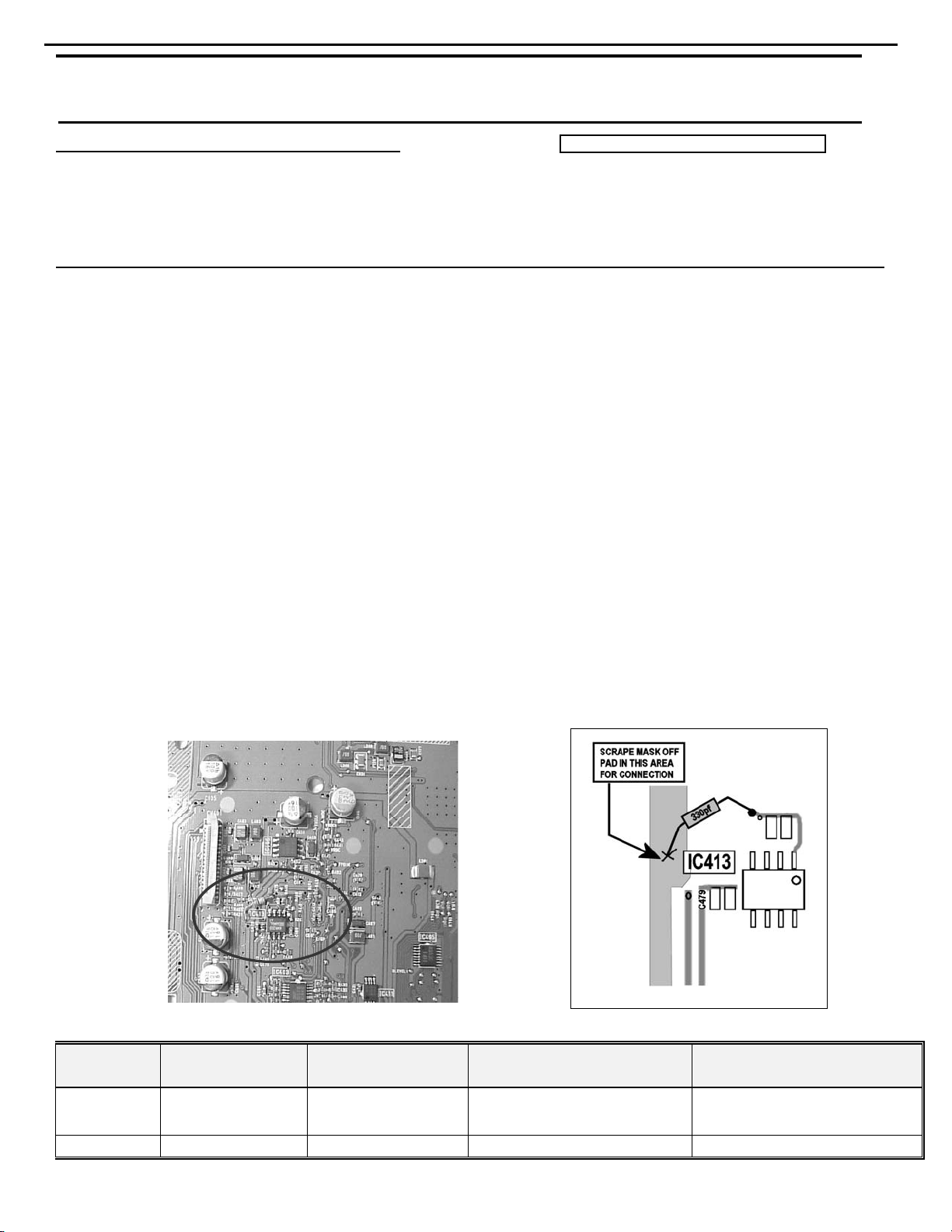
Synopsis: Add a 330 pf ceramic capacitor from pin #1 on IC413 Op-amp to Ground.
1) With the unit plugged in, turn it ON. Press the eject button on the Record side to open the drawer.
2) With the drawer fully extended, carefully lift up on the front trim to separate it, and off the main part of the
drawer. Press the eject buton again to close the drawer. Turn the unit OFF and unplug it.
3) Remove the (7) Phillips screws holding the top cover on; remove the top cover.
4) Unplug the three connectors at the rear of the Record PCB.
5) Unscrew the (4) black Phillips screws that are deep in the slotted wells in each corner of the Record
mechanism. Lift the entire Record assembly up and out of the unit.
6) Remove the gray metal shield from the assembly. Lay the assembly upside-down on a table, PCB facing
upwards.
7) The PCB can be disengaged from the assembly by depressing the two black plastic tabs on opposite sides of
the PCB and lifting, in sequence.
8) CAREFULLY lift the PCB off the assembly, noting the (4) connectors that are attached to the PCB. Unplug the
three ribbon connectors. (NOTE: the largest female connector on the PCB has a locking collar which must be
lifted to disengage the cable); the mustard-colored molex connector can remain in place, “hinge” the PCB open
enough to lay it flat on the table.
9) Locate the area of concern with the aid of the illustrations. Solder a 330pf ceramic capacitor,
(h/k part# 147-75-331) from electrical equivalent pin #1 on IC431 Op-amp to Ground.
10) Reassemble and replace the record mechanism in reverse order; test the unit by inserting a blank CDR disc in
the Record drawer and note the time delay.
Warranty labor rate: MINOR repair
Service Bulletin
Model Serial num ber
120V
CDR20
CDR20 LG0003-27201 LG0004-07631 Factory Installed NONE REQUIRED
LG0003-01001
to
LG0003-27200
Serial num ber
230V
LG0004-01001
to
LG0004-07630
Status Action
May have long time delay when
reading a b lank CDR dis c
Add 330 pf capacitor fr om pin #1
on IC413 Op-am p t o G r ound
Page 17
17
CDR20
harman/kardon
harman/kardon
Service bulletin # H/K2001-06 November 2001
To: All harman/kardon Service Centers
Model: CDR20
Subject: Noise when dubbing at x4 speed
In the event you receive a CDR20 CD Player/Recorder with the complaint: “There is noise being
generated on a r ecorded CDR at x4 speed”, perform the modification below:
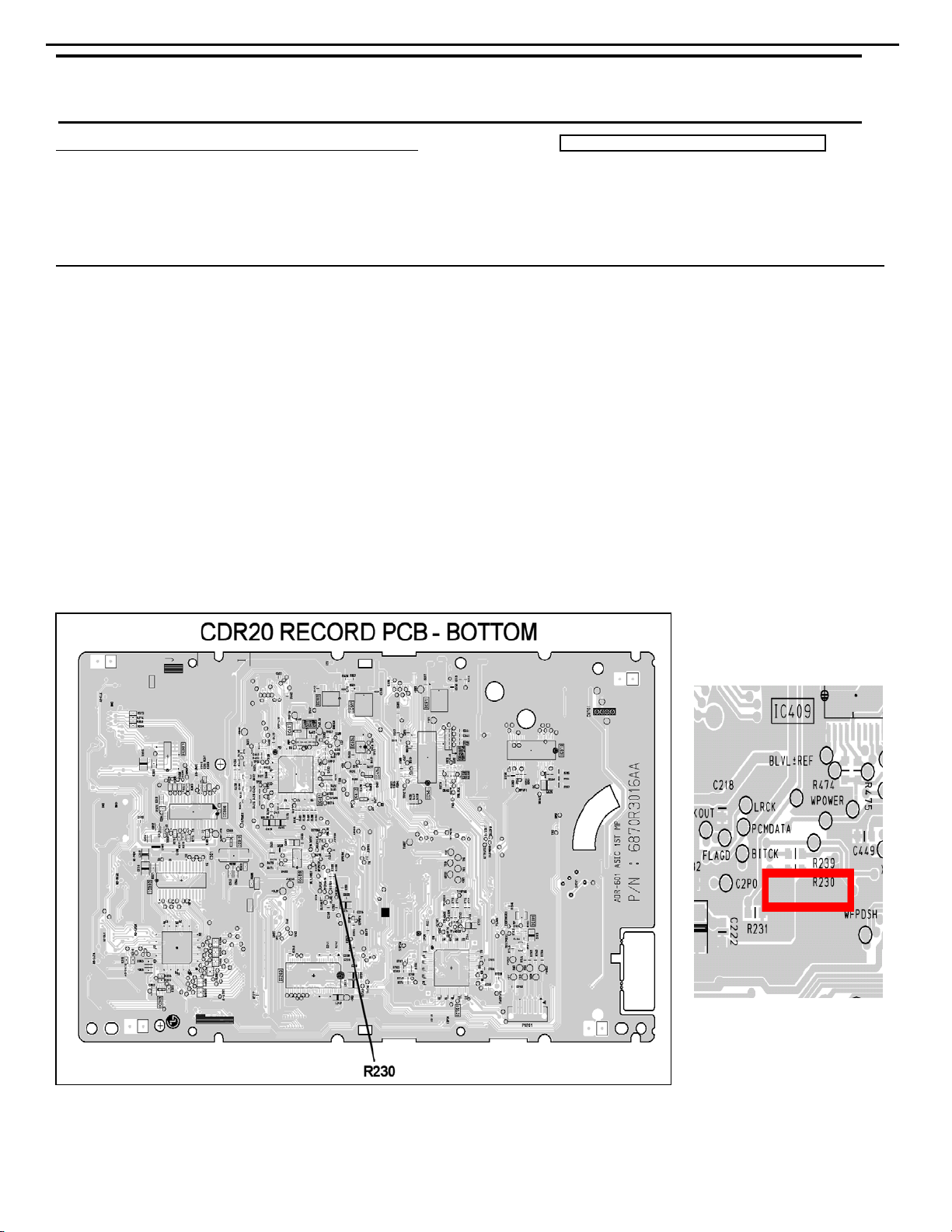
Synopsis: Change re sistor R230 from 100 ohms to 22 ohms.
1) With the unit plugged in, turn it ON. Press the eject button on the Record side to open the drawer.
2) With the drawer fully extended, carefully lift up on the front trim to separate it, and off the main part of the
drawer. Press the eject buton again to close the drawer. Turn the unit OFF and unplug it.
3) Remove the (7) Phillips screws holding the top cover on; remo ve the top cover.
4) Unplug the three connectors at the rear of the Record PCB.
5) Unscrew the (4) black Phillips screws that are deep in the slotted wells in each corner of the Record
mechanism. Lift the entire Record asse mbly up and out of the unit.
6) Remove the gray metal shield from the assembly. Lay the assembly upside-down on a table, PCB facing
upwards.
7) Locate the area of concern with the aid of the illustrations. Change SMD resistor R230 from 100 ohms to
22 ohms, h/k part# 301-22.
Reassemble and replace the record mechanism in reverse order; test the unit by inserting a blank CDR disc and
8)
making a recording at x4 speed to assure the noise problem is gone.
Warranty labor rate: MINOR repair
Service Bulletin
See Page 2 for serial numbers of Factory Modified Units
Page 18

18
CDR20
Service bulletin # H/K2001-06 November 2001
harman/kardon
FACTORY MODIFIED UNITS
(120v)
All Serial Numbers begin with prefix LG0003-
28111 28335 28415 28910 29164 29655
28230 28336 28417 28914 29172 29659
28234 28337 28418 28918 29181 29666
28241 28338 28431 28921 29183 29693
28244 28339 28432 28924 29184 29711
28247 28340 28442 28926 29195 29748
28260 28341 28468 28945 29236 29772
28264 28342 28475 28956 29277 29783
28272 28343 28481 28960 29300 29788
28280 28343 28488 28971 29301 29803
28281 28345 28489 28973 29302 29805
28282 28346 28509 28986 29303 29808
28283 28347 28521 28995 29306
28284 28348 28522 28998 29308
28285 28349 28525 29002 29309
28286 28350 28526 29007 29310
28287 28351 28531 29009 29328
28288 28352 28533 29010 29330
28289 28353 28545 29012 29331
28290 28354 28547 29028 29344
28291 28355 28551 29029 29364
28292 28356 28625 29031 29393
28303 28363 28638 29033 29405
28317 28370 28648 29039 29409
28318 28371 28662 29045 29414
28319 28372 28715 29046 29419
28320 28373 28719 29053 29446
28321 28374 28763 29059 29453
28322 28376 28813 29067 29461
28323 28378 28816 29088 29474
28324 28379 28820 29089 29478
28325 28380 28827 29105 29481
28326 28382 28849 29114 29559
28327 28383 28862 29131 29570
28329 28384 28863 29135 29578
28330 28385 28872 29138 29581
28331 28387 28876 29141 29620
28332 28389 28890 29154 29630
28333 28391 28893 29155 29634
28334 28402 28909 29159 29648
Also units in the range LG0003-29853 - LG0003-30640
Page 19
TROUBLESHOOTING GUIDE
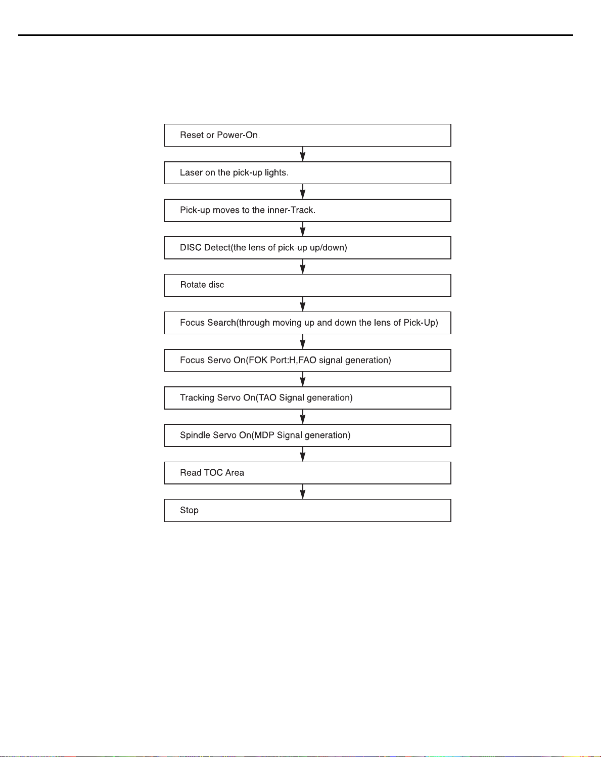
1. Initial Lead-in Operation
2. Trouble List(Circuit)
(In the Initial Lead-in Operation Mode)
A. Pick-Up doesn’t move to the inner-track.
B. Pick-Up lens doesn’t move up and down.
C. Disc doesn’t rotate.
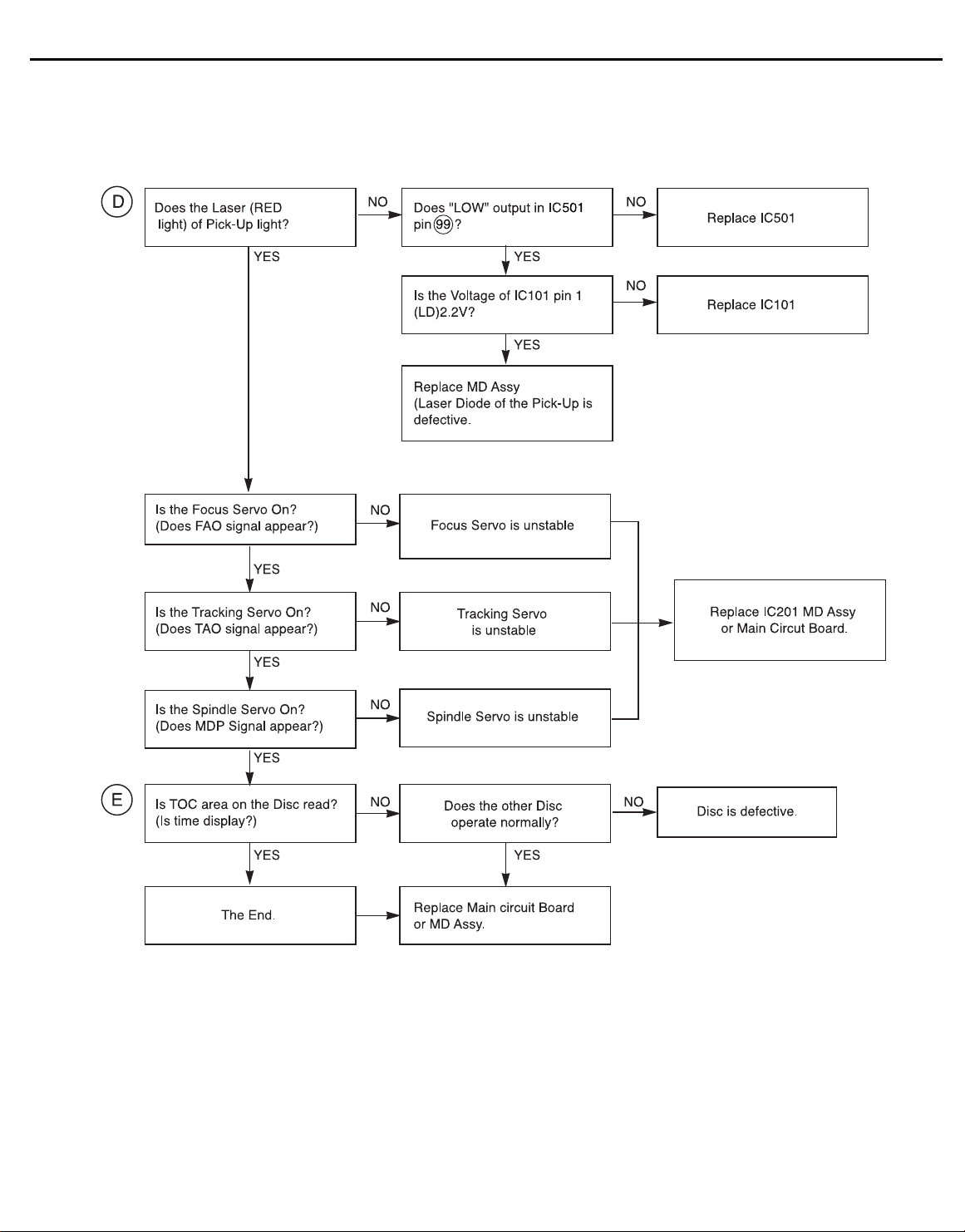
D. The Laser(RED) of Pick-Up doesn’t light.
E. TOC isn’t read.
19
CDR20
harman/kardon
Page 20
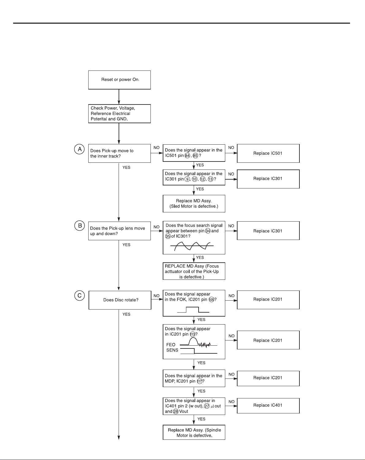
3. Troubleshooting Guide(In the Initial Lead-in Operation Mode)
20
CDR20
harman/kardon
Page 21
21
CDR20
harman/kardon
Page 22
22
CDR20
harman/kardon
Page 23
23
CDR20
harman/kardon
Page 24

24
CDR20
harman/kardon
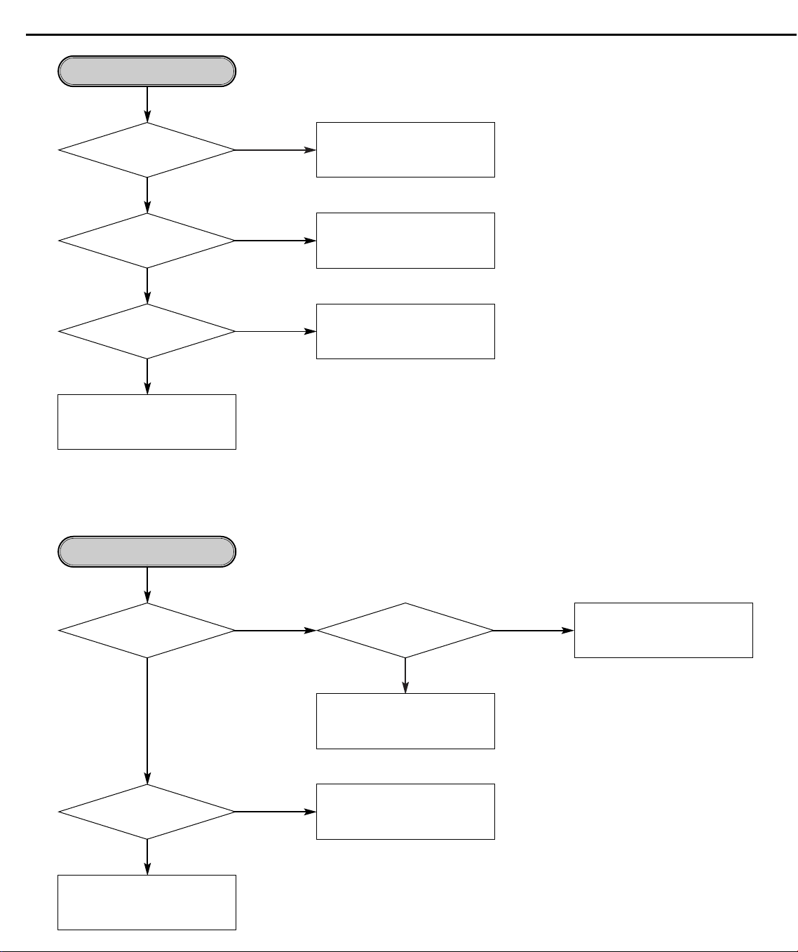
TROUBLESHOOTING GUIDE FOR CD-RW BOARD
Reset or Power Check.
•Is the Pin 1, 3 of PN105 5V?
•Is the Pin 5 of PN105 12V?
YES
of IC101 change 0V to 5V at the power
Are the X701 and X301 oscillating?
•Is the Pin7 of IC514 2.5V?
•Is the pin1 and 2 of IC514 2.0V?
Does the pin1
supply initial input mode?
YES
YES
•Is the pin4 of IC103 3.9V?
•Is the Pin32 of IC401 2.0V?
•Is the Pin4 of IC102 3.3V?
YES
NO
NO
NO
NO
NO
• Check the PN105.
• Check the SMPS board.
• Check the IC101(RESET IC).
• Check the IC301(HD64F3062),
IC301(XC10TQ80)
•Check the X701, X301.
•Check the IC701, IC301.
•Check the IC103(BA3939).
•Check the IC401(CXA2551R).
•Check the IC102(BA033S).
Check the IC514(NJM3414).
YES
•Is the pin1 of IC511 8.0V?
•Is the pin1 of IC512 8.0V?
YES
OK
NO
•Check the IC511(NJM7808).
•Check the IC512(NJM7808).
Page 25
25
CDR20
System Check.
Load tray without inserting disc.
harman/kardon
Does Tray operate normally?
YES
Does Pick-up move to inside?
YES
Does Spindle Motor rotate in a moment?
YES
Does Lens move Up/Down?
YES
Does Laser turn on?
YES
After eject tray, Inset CD Disc and reloading.
Does Disc stop?
NO
NO
NO
NO
NO
YES
Go to "Tray operating is abnormal"
Go to "Sled operating is abnormal"
Go to "Spindle opreating is
abnormal"
Go to "Focus Actuator operating is
abnormal"
Go to "Laser is abnormal"
Go to "Spindle control is abnormal 1"
NO
Does Disc rotate
continuously as Disc recognition
is abnormal?
NO
After eject tray, Inset CD-R Blank
Disc and reloading.
NO
Does Disc stop?
NO
Does Disc rotate
continuously as Disc recognition
is abnormal?
NO
OK
YES
YES
YES
Go to "Spindle control is abnormal 2"
Go to "Spindle control is abnormal 3"
Go to "Disc recognition is abnormal"
Page 26
26
CDR20
Tray operating is abnormal.
(Tray open/close doesn't work)
harman/kardon
Is threre Tray control signal intput?
Is three Tray drive voltage output?
•Check the Tray Connector(CN701).
•Check the Motor Line and Motor.
(IC501 pin26)
YES
(IC501 pin15, 16)
YES
NO
NO
•Check the connection of IC409 pin 12.
•Replace the IC409(M62352).
•Check the communication line between
IC409 and IC701(MICOM).
Is TRAY_MUTE
signal"L"?(IC501 pin20)
YES
When CN701
is open, Is there Tray drive
signal output?
YES
NO
NO
•Check the connection of IC701
pin 25.
•Replace the IC301.
Replace the IC501(BA5983FM).
Page 27

27
CDR20
Sled operating is abnormal.
harman/kardon
Sled control signal output?
Sled drive voltage input?
Sled drive voltage output?
HALL/SLDOUT signal input?
Is there
(IC701 pin 85)
YES
Is there
(IC501 pin 23)
YES
Is there
(IC501 pin 17, 18)
YES
Is there
(IC701 pin82)
NO
NO
NO
NO
Check the connection of IC701
pin 85
Check the connection of IC502
pin 17.
Replace the IC502(BA5925)
Is Act_Mute signal "L"?
(IC501 Pin9)
YES
Replace the IC501(BA5983)
Is there HALL 1
signal input (IC508 pin3)
NO
NO
YES
Replace the IC701(MICOM)
Check the connection of IC701
pin 26.
Replace the IC508(BU4053)
YES
Is there
SLED FG signal input?
(IC701 pin97)
YES
OK
NO
NO
Check the IC502(BA5925)
•Check the Connector(CN501)
•Replace the SLED Motor.
Page 28

28
CDR20
Spindle operating is abnormal.
harman/kardon
Is there Spindle
control signal input?
(IC510 pin 22)
YES
Is there Spindle
drive voltage output?
(IC510 pin 2,4,7)
YES
NO
NO
Is there DMO signal input?
(IC509 pin5)
YES
Is there Spindle
control signal output?
(IC509 pin 7)
YES
Replace the IC508(BU4053).
Is SPNON signal “H”?
(IC510 pin 23)
YES
Is SBRK signal “L”?
(IC510 pin 18)
NO
•Check the connection of IC201 pin2.
•Replace the IC201(OTI-9790)
NO
NO
NO
•Replace the IC509(NJM3404).
•Check the connection of IC301 pin99.
•Replace the IC701(MICOM)
•Check the connection of IC701 pin94.
•Replace the IC701(MICOM)
•Check the spindle Connector
(CN502)
•Replace the Spindle Motor.
YES
Is there
a SPNFG signal input?
(IC701 pin 7, IC201
pin 95)
YES
OK
NO
•Check the connection of IC510 pin19.
•Replace the IC501(BA6664FM)
Page 29

29
CDR20
Focus Actuator operating
is abnormal
harman/kardon
Focus Search control signal
Is there
input? (IC510 pin 3)
YES
Is there Focus Search
drive voltage output?
(IC501 pin 13,14)
YES
•Check the connection of PN401 Pin 1,4.
•Check the Pick-up Connector(CN401).
Replace the Pick-Up.
NO
NO
•Check the connection of IC201 pin207.
•Check the communication line between
IC201 and IC701
•Replace the IC201(OTI-9790)
Is Act_Mute signal “L”?
(IC501 pin 9)
YES
Replace the IC501(BA5983).
NO
•Check the connection of IC701
pin26.
•Replace the IC701(MICOM)
Spindle control is abnormal 1
(CD-ROM DISC)
Does FOCUS Servo
operate normally?
YES
Is there RFAC signal input?
(IC201 pin 163)
YES
Go to “Spindle operating is
abnormal”
NO
NO
Go to “Focus Servo is unstable”
Is there a output normally?
(IC401 pin 71, 72)
YES
Replace the IC413(EL2245).
NO
Replace the IC401(CXA2551R).
Page 30
30
CDR20
Spindle control is abnormal 2
(CD-ROM Disc)
harman/kardon
Is there
RRF signal input?
(IC413 pin 3)
YES
Is there
RFDC signal input?
(IC401 pin 85)
YES
Does Tracking
Servo operate normally?
YES
Go to “Disc recognition is abnormal”
NO
NO
NO
Go to “RF output is abnormal”
Replace the IC413(EL2245).
Go to “Track servo is unstable”
Spindle control is abnormal 3
Is there WBLIN signal
input? (IC201 pin 132)
YES
Is there DMO signal
output? (IC202 pin 2)
YES
Go to “Spindle operating is
abnormal”
NO NO
NO
Is there ATFM signal
output? (IC401 pin 25)
YES
Replace the IC401(CXA2551R).
Replace the IC201(OTI-9790).
Go to “RF output is abnormal”
Page 31

31
CDR20
Disc recognition is abnormal
harman/kardon
Is there
CDR/RW signal input
normally?(IC601 pin 33)
YES
RF output is abnormal
Is there
PICK UP(A,B,C,D) output
normally? (CN401 pin 8,9,
14,15)
YES
Is RRF signal
output normal?(IC401 pin 86)
•First Recognition try : Over 1.7 Vpp
•Second Recognition try :
Over 0.5 Vpp
NO
NO NO
NO
output normally? (IC401 pin
Replace IC701 (MICOM)Go to “Track Servo is unstable”
•Check the PICK UP FFC.
•Replace the PICK UP
•Check the connection between
CN401 and IC401.
•Replace the IC401(CXA2551R).
Is there
RECD1, RECD2 signal
48,49)
YES
NO
Go to “RF output is abnormal”
Go to “Laser is abnormal”
YES
OK
Page 32

32
CDR20
Focus Servo is unstable
harman/kardon
Is FE signal
output normal in Focusing
Up/Down? (IC401
pin 56)
YES
Is FAQ signal
output normal in Focusing
Up/Down? (IC201
pin 207)
Go to “Focus Actuator operating
is abnormal”
Track Servo is unstable
Is TE signal
output normal in Focusing ON
and Tracking OFF?
(IC401 pin57)
YES
NO
NO
NO NO
Check the IC401(CXA2551R).
Go to “RF output is abnormal”
Replace the IC201(OTI-9790).
Is PICK UP(E,F,G,H)
output normal?(CN401
pin 16,7,13,10)
YES
•Check the PICK UP FFC.
•Replace the PICK UP.
Is TE signal
input normal in Focusing
ON and Tracking OFF?
(IC201 pin198)
YES
Is
there TAO signal
output in Tracking ON?
(IC201 pin 208)
YES
Check the Driver IC(IC501) and
P/U referring to “Focus Asctatr
operating is abnormal.”
NO
NO
Check the IC401(CXA2551R).
YES
Go to “RF output is abnormal”
Check the IC403(NJM3403)
Replace the IC201(OTI-9790).
Page 33

33
CDR20
In case of writing fail.
Nomal Case
harman/kardon
Cheak the Media CD-R
or CD-RW?
YES
Dose the disc have
any Dust, Scratch,
Fingerprint...?
NO
Finalized Disc?
YES
If CD-R disc, use new CD-R disc.
If CD-RW disc, erase the dise.
NO
YES
NO
Check disc Label.
Romove the Dust, Fingerprint
and if the disc has long width
Scratch, change it.
Eject Disc.
Go to “Writing Part Check”
Page 34

34
CDR20
Writing Part Check.
Refer “Laser is abnormal”.
Load tray with CD-R/RW Disc.
Start Recording or dubbing.
harman/kardon
Does the unit
becomes stand-by mode to
record/dubbing?
YES
Dose Writing finish
without any error?
YES
Is the written file
read nomally?
YES
YES
NO
NO
NO
•Check the communication Iines
between IC701 and IC201.
•Check and replace the 701.
Eject Tray.
Go to “ALPC Logic Circuit Check”.
Is the re-written file
readed nomally?
NO
OK
Check the connection of IC201
pin 187 and replace IC201.
ROPCSH input signal
Is
Pulse when CD-R writing
(IC401 pin 43)
YES
Go to “BETAMeasurement
Circuit Check”.
Page 35

35
CDR20
BETAMeasurement circuit ceck
After inserting Test Dise(TCD-784),
start playing.
harman/kardon
IC401 Pin 86(RRF):3+/-1.0V?
YES
RRFIN:2+/0.7V?
(IC401 PIN85)
YES
IC405 Pin 10(CDR/RWS)=“H”?
YES
IC701 Pin 78(RFBETA):
2+/-1.0V?
YES
K
NO
NO
NO
NO
•Check the connection of IC401 pin 86.
•
Check and replace the IC401
(CXA2551R).
•Check the connection of IC407.
•Check and replace the IC407.
•Check the connection of IC701 pin 20.
•Check and replace the IC701(MICOM).
Is BETAsignal nomal?
(IC405 pin 14)
YES
Check the replace the IC405(BU4052)
NO
•Check the connection of IC401 pin 82.
•Check and replace the IC401.
Page 36

BLOCK DIAGRAM
I / V AMP
LD
Driver
Spindle
motor
Sled
motor
Pick-up
(KRS-220c
:Sony)
disc
BA5983FM
F.T.S.T drive
BA6664FM
Motor drive
BA5925
Sled Speed
M62352
12CH
8 bit DAC
AT93C86
1KB
EEPROM
S/H 17.43MHz
20MHz
RF/Servo Signal
Timing
Signal
ASIC
VC00S01
256K
SRAM
D-out
CDP
I/O
33.86MHz
I/F
Serial data
MCLK
Serial /AES3
output
CXA2551R
RF AMP
Wobble
ALPC
OTI9790
DSP + SERVO
Decoder
Encoder
ATIP Demod.
Write Strategy
I/F
2MB
DRAM
SRC
CS8420
OPC/
ROPC
Circuit
H8/3062
System
Controller
CPLD
Laser Control
S/H Signal Gen
36
• CD RECORD SECTION
CDR20
harman/kardon
Page 37

• CD PLAY SECTION
37
CDR20
harman/kardon
Page 38

• IO SECTION
C
D
P
C
D
R
W
BU4053
S/W
BU4053
S/W
AK4394
(DAC)
AK4394
(DAC)
AK4394
(DAC)
AK4394
(DAC)
LRCK
DATA
BCLK
BU4053
S/W
BU4053
S/W
MCK(P)
MCK(R)
LRCK
DATA
BCLK
TC4W53
S/W
TC4W53
S/W
74HC04
BUFFER
74HC04
BUFFER
ANALOG P OUTPUT
ANALOG R OUTPUT
ANALOG INPUT
COAXIAL P OUT
COAXIAL R OUT
COAXIAL IN(2)
74HC04
BUFFER
74HC04
BUFFER
74HC04
BUFFER
74HC04
BUFFER
OPTICAL R OUT
OPTICAL IN
RELAY
F
R
O
N
T
AK5351
(ADC)
AK5351
(ADC)
74HC04
BUFFER
74HC04
BUFFER
BCK
DATA
LRCK
H/P OUT
74HC04
BUFFER
74HC04
BUFFER
COAXIAL
IN (1)
REC
VOL.
POWER
DOWN
MUTE
DEMPH
MUTE
DEMPH
CDP-DOUT
CDR-DOUT
EQ LEVEL
L/R
CDP/CDR
38
CDR20
harman/kardon
Page 39

EXPLODED VIEW
403
403
257
403
255
279
403
403
404
A49
403
403
403
A47
403
403
403
275
403
401
401
401
276
403
401
401
401
401
404
404
403
251
250
252
A48
254
256
258
259
278
403
260
259
403
278
403
259
259
278
403
277
262
266
267
A43
263
261
262
264
266
270
A43-4
A43-3
A43-2
A43-2
267
268
270
269
268
405
405
404
A48-1
A48-2
A46
A45
A44
404
265
A46-1
S AL LOCA. NPART NO.(LG) A DESCRIPTION SPECIFICATION REMARKS
ASSEMBLY SECTION
A43 3721R-M001C O PANEL ASSY,AUDIO FORNT+PCB(ADR-601.KTH1K)
A43-1 3721S-M111B O PANEL ASSY,FRONT ADR-601 KTH1K
A43-2 6871RJ1963C O PWB(PCB) ASSY,JACK(AUDIO) AADR600 KTH1 H/P,COXIAL
A43-3 6871SF42GAE O PWB(PCB) ASSY,FRONT AADR600 KTH1 EMI2
A43-4 6871RU0001B O PWB(PCB) ASSY,SUBSET(AUDIO) AADR600 KTH1 REC VOLUME
A44 6721R-0311A O DECK ASSY,AUDIO AADR601 E2+PCB
A45 6721R-W222A O DECK ASSY,AUDIO AADR601 PCB+Q1
A46 3141R-0007S O CHASSIS ASSY MAIN(AADR601.KTH1K)
A46-1 3610RB0001A O FOOT BOTTOM ASS''Y(GOLD ADR-600)
A47 6871R-3072A O PWB(PCB) ASSY,TOTAL ADR-601 KTH1K I/O
A48 4941R-0002A O KNOB ASSY POWER+PCB(ADR-600 KTH1)
A48-1 4941RB0001A O KNOB ASSY POWER(ADR-600 KTH1)
A48-2 6871RZ1963A O PWB(PCB) ASSY,OTHERS CDR-600 AH1 FRONT POWER LED
A49 3501R-3060A O BOARD ASSY ADR-601 SMPS PWB
PARTS SECTION
250 4940S-6939A O KNOB POWER(ADR-600 KTH1)
251 3790S-M079A O WINDOW POWER LENS(CDR 2 AH1)
252 3300R-X002A O PLATE PET 713F 0.15T PI9.9
254 4510S-1019A O LEVER POWER(CDR 2)
255 3580S-C108B O DOOR PLAY(ADR-600 KTH1 PRINT2)
256 3580S-C105B O DOOR ACDR(ADR-600 KTH1 2PRINT)
259 3610S-0192A O FOOT BOTTOM(ADR-600 KTH1)
260 3140S-P913B O CHASSIS MAIN(ADR-600 KTH1)
261 3790S-M072B O WINDOW FRONT(ADR-601 KTH1)
262 4350S-0001A O RING 3KEY(ADR-600 KTH1)
263 4350S-0002A O RING 6KEY(ADR-600 KTH1)
264 3858S-X170A O SHEET (MECH) FL(CDR 2 AH1)
265 3720S-M113A O PANEL,FRONT FRONT(ADR-600 KTH1)
266 3858S-X171A O SHEET (MECH) ETC
267 4940S-6938A O KNOB PLAY 3K(ADR-600 KTH1)
268 4940S-6937A O KNOB SEESAW 4K(ADR-600 KTH1)
269 4940S-6940A O KNOB REC 8K(ADR-600 KTH1)
270 4940S-6941A O KNOB VOLUME(ADR-600 KTH1)
275 3720S-P014K O PANEL BACK(ADR601. KTH1)
276 3140S-P911C O CHASSIS TOP(ADR-600KTH1 HARMAN)
277 3846S-0208A O MARK HARMAN KARDON BADGE
278 4766R-0003A O FELT FOOT(19.7*19.7)
279 3550S-1027B O COVER RW DECK(AIR VENT ADR-600 KTH1)
300 6410RAHS02A O POWER CORD AP-10W NI SP2 CORE 80 STP SANG
39
• MAIN SECTION
CDR20
harman/kardon
Page 40

• CD PLAY SECTION
006
009
010
436
014
013
025
020
026
434
027
028
029
033
435
435
030
034
031
031
431
431
035
032
431
012
007
A01
A02
A00
A03
008
011
001
002
40
CDR20
harman/kardon
Page 41

435
109
108
107
440
100
437
113
112
720
114
110
430
131
125
439
439
126
127
128
126
132
151
153
152
438
129
439
441
130
150
131
430
154
111
106
A10
A11
A12
• CD RECORD SECTION
41
CDR20
harman/kardon
Page 42

SECTION 5 REPLACEMENT PARTS LIST
A : CDR 20 KTH1K
RUN : 2000.10.28
. Mechanical Section
NSP : Not Service Parts
S AL LOCA. NPART NO.(LG) A DESCRIPTION SPECIFICATION REMARKS
ASSEMBLY SECTION
A00 6721R-0301A O DECK ASSY,VIDEO ACDR(Q1,PLYER)
A01 4405H-1064A O MECHANISM ASSY MAIN LOADING(GM-RT1332A)
A02 4931R-0033A O HOLDER ASSY CLAMP(Q1,ACDR)
A03 4405R-D001A O MECHANISM ASSY PU UNIT
A10 6721R-0302B O DECK ASSY,VIDEO ACDR(E5,RECODER)
A11 4405H-1070C O MECHANISM ASSY LOADING(GM-WT1524A,HORIZON
A12 4405R-D001B O MECHANISM ASSY ACDR PU UNIT(E5)
PARTS SECTION
001 4861R-0004A O CLAMP ASSY Q1 & E2 ACDR
002 4930H-1061A O HOLDER CLAMP(GM-RT1332A)
006 4400H-1009A O BELT GM-RT1332A
007 4970H-1087A O SPRING LEVER SWITCH (GM-RT1332A)
008 4510H-1033A O LEVER SWITCH(Q1)
009 4560H-1015A O PULLEY GEAR (Q1)
010 4470H-1115A O GEAR LOADING(Q1)
011 3040H-1056A O BASE UP/DOWN(Q1)
012 3040H-1055A O BASE MAIN (Q1) NSP
013 4681H-1024A O MOTOR ASSY LOADING(H1 TO V3)
014 4974H-1034A O GUIDE UP/DOWN(Q1)
020 3390H-1016C O TRAY DISC (IBM, BLACK)
025 6716S-E001A O PICK UP SF-P151EXVA SANYO ACDR
026 6850HD1L16A O CABLE,FLEXIBLE 2896-A-1.0-17(05*65)160 BANDO
027 4974H-1039A O GUIDE FEED (Q1, MATSUSHITA)
028 4970H-1086A O SPRING FEED(GM-RT1332A)
029 4370H-1024C O SHAFT P/U (R,GM-RT1332A)
030 4370H-1025B O SHAFT P/U (L,GM-RT1332A)
031 5040H-1053A O RUBBER GM-RT1332A (F)
032 4680HB1019A O MOTOR(MECH) GCS-L32A LGEC SPINDLE
033 5040H-1052A O RUBBER GM-RT1332A(R)
034 3040H-1057A O BASE P/U(Q1)
035 4680HP5002B O MOTOR(MECH) 15S1R10F6NC3 MATSUSHITA STEPPI
100 4861H-0008A O CLAMP ASSY GM-WT1524A
106 4400H-1003A O BELT GM-R512
107 4560H-1004A O PULLEY GEAR
108 4470H-1015A O PULLEY GEAR, LOADING(GM-R512)
109 4470H-1016A O PULLEY GEAR, MIDDLE(GM-R512)
110 4974H-1018A O GUIDE PLATE
111 3040H-1059A O BASE UP/DOWN(E2)
112 4681H-1024A O MOTOR ASSY LOADING(H1 TO V3)
113 3040H-1035B O BASE MAIN(E2)
114 4974H-1023A O GUIDE UP/DOWN(K1)
120 3390H-1011D O TRAY DISC(E2/HORIZONTAL/BLACK)
125 4810H-1042A O BRACKET WEIGHT BALANCER
126 5040H-1055B O RUBBER FRONT(E4)
127 6716R-E002A O PICK UP KRS-220C SONY 4RWX4RX32CD
128 4471H-0003A O GEAR ASSY RACK(E2)
129 4471H-0004A O GEAR ASSY PINION(E2)
130 4405H-1084B O MECHANISM ASSY SLED UNIT(E3,NEW HALL PCB)
131 5040R-0047A O RUBBER REAR(E2,5040H-1054A),YAMAUCHI
150 3140H-1010A O CHASSIS P/U(E2) NSP
151 4680HB1034A O MOTOR(MECH) GRS-R02A LGP SPINDLE NSP
152 4370H-1078A O SHAFT P/U(L/CD-RW) NSP
153 4930H-1075A O HOLDER FFC (E4) NSP
154 4370H-1079A O SHAFT P/U(R/CD-RW) NSP
SCREW&WASHER
401 353-633A O SCREW TAPTITE 4X8 BK S-TYPE
403 353-046K O SCREW SPECIAL (3X10 B.K)
42
CDR20
harman/kardon
Page 43
RUN : 2000.10.28
NSP : Not Service Parts
S AL LOCA. NPART NO.(LG) A DESCRIPTION SPECIFICATION REMARKS
404 353-051AAAA O SCREW TAP/T,WASHER 3X10 FZY,H/D:9.5
404 353-051AAAA O SCREW TAP/T,WASHER 3X10 FZY,H/D:9.5
405 353-051A O SCREW SPECIAL
431 1SZZH-1007B O SCREW, + D2.0 6MM SWRCH16A/ZNBK 4MM 1
434 1SZZH-1011B O SCREW + D1.7 6MM SWRCH16A/NIY 3.5MM
435 1SZZH-1004A O SCREW, + D1.7 5MM SWRCH16A/ZNY 3.5MM
436 4000H-1006B O SCREW + D1.7 4.5MM SWRCH16A/ZNY 4MM
437 4000H-1006A O SCREW, + D1.7 4MM SWRCH16A/ZNBK 3MM 0
438 1WZZH-1009A O WASHER BLACK Y POLY N
440 1SZZH-1011A O SCREW, + D1.7 7MM SWRCH16A/ZNY 3MM 0.
441 1SZZH-1005A O SCREW + D1.7 5MM SWRCH16A/NIY 3MM 0.
. Cabinet & Main Frame Section
ASSEMBLY SECTION
A43 3721R-M001C O PANEL ASSY,AUDIO FORNT+PCB(ADR-601.KTH1K)
A43-1 3721S-M111B O PANEL ASSY,FRONT ADR-601 KTH1K
A43-2 6871RJ1963C O PWB(PCB) ASSY,JACK(AUDIO) AADR600 KTH1 H/P,COXIAL
A43-3 6871SF42GAE O PWB(PCB) ASSY,FRONT AADR600 KTH1 EMI2
A43-4 6871RU0001B O PWB(PCB) ASSY,SUBSET(AUDIO) AADR600 KTH1 REC VOLUME
A44 6721R-0311A O DECK ASSY,AUDIO AADR601 E2+PCB
A45 6721R-W222A O DECK ASSY,AUDIO AADR601 PCB+Q1
A46 3141R-0007S O CHASSIS ASSY MAIN(AADR601.KTH1K)
A46-1 3610RB0001A O FOOT BOTTOM ASS’’Y(GOLD ADR-600)
A47 6871R-3072A O PWB(PCB) ASSY,TOTAL ADR-601 KTH1K I/O
A48 4941R-0002A O KNOB ASSY POWER+PCB(ADR-600 KTH1)
A48-1 4941RB0001A O KNOB ASSY POWER(ADR-600 KTH1)
A48-2 6871RZ1963A O PWB(PCB) ASSY,OTHERS CDR-600 AH1 FRONT POWER LED
A49 3501R-3060A O BOARD ASSY ADR-601 SMPS PWB
PARTS SECTION
250 4940S-6939A O KNOB POWER(ADR-600 KTH1)
251 3790S-M079A O WINDOW POWER LENS(CDR 2 AH1)
252 3300R-X002A O PLATE PET 713F 0.15T PI9.9
254 4510S-1019A O LEVER POWER(CDR 2)
255 3580S-C108B O DOOR PLAY(ADR-600 KTH1 PRINT2)
256 3580S-C105B O DOOR ACDR(ADR-600 KTH1 2PRINT)
259 3610S-0192A O FOOT BOTTOM(ADR-600 KTH1)
260 3140S-P913B O CHASSIS MAIN(ADR-600 KTH1)
261 3790S-M072B O WINDOW FRONT(ADR-601 KTH1)
262 4350S-0001A O RING 3KEY(ADR-600 KTH1)
263 4350S-0002A O RING 6KEY(ADR-600 KTH1)
264 3858S-X170A O SHEET (MECH) FL(CDR 2 AH1)
265 3720S-M113A O PANEL,FRONT FRONT(ADR-600 KTH1)
266 3858S-X171A O SHEET (MECH) ETC
267 4940S-6938A O KNOB PLAY 3K(ADR-600 KTH1)
268 4940S-6937A O KNOB SEESAW 4K(ADR-600 KTH1)
269 4940S-6940A O KNOB REC 8K(ADR-600 KTH1)
270 4940S-6941A O KNOB VOLUME(ADR-600 KTH1)
275 3720S-P014K O PANEL BACK(ADR601. KTH1)
276 3140S-P911C O CHASSIS TOP(ADR-600KTH1 HARMAN)
277 3846S-0208A O MARK HARMAN KARDON BADGE
278 4766R-0003A O FELT FOOT(19.7*19.7)
279 3550S-1027B O COVER RW DECK(AIR VENT ADR-600 KTH1)
300 6410RAHS02A O POWER CORD AP-10W NI SP2 CORE 80 STP SANG
. Packing Accessory Section
801 3829RDK006D O MANUAL ASSY ADR-600N(CDR 20) USA 5CARD+O/M
802 3890S-C093Y O BOX AADR601 HARMAN DW2 561/456/198
803 3920R-0087A O PACKING ADR-600 0.02 400 EPS 6 660 132
804 292-053D O BAG LVP-1 NSP
808 534-002C O BATTERY 1.5V AAM UM-3 LOL 1PAIR
850 3008R-0004A O DISK CD-R HARMAN KARDON(2ND)
851 564-036D O PLUG CONTACT CORD,PHONE PHONE 1.5MZ 1185#26
852 564-036J O CORD DIGIATL 1.5M 1365#30 ORANGE N
853 6852R-N001A O CORD 1.5M NAMIL REMOTE CONTROL FO
. Remote Control Section
900 6711R1Z017B O REMOTE CONTROLLER ASSY HANHGO 43KEY ACDR CDR20RC
43
CDR20
harman/kardon
Page 44
A : CDR 20 KTH1K
. Electrical Section RUN : 2000.10.28
S AL LOCA. NO. PART NO.(LG) A DESCRIPTION SPECIFICATION
CAPACITOR
C249 0CH1104K946 O CAPA,CHIP CERAMIC M/L H.D F/S 0.1UF 50V Z Y5V(F) 2012 R/TP
C101 0CE4766J618 O CAPACITOR,ELECTROLYTIC 47M SMS 35V M FM(5) TP(5)
C101 0CH1104K942 O CAPACITOR,CHIP[CERAMIC M/L HD 0.1UF 50V Z Y5V(F) 1508 R/TP
C101 0CHZS-0001B O CAPACITOR,CHIP GRM39X7R103K50C500 PT266 MURAT
C102 0CH1102K566 O CAPACITOR,CHIP[CERAMIC M/L HD 1000PF 50V K X7R(X) 2012 R/TP
C102 0CH1104K942 O CAPACITOR,CHIP[CERAMIC M/L HD 0.1UF 50V Z Y5V(F) 1508 R/TP
C102 0CH8107C621 O CAPACITOR,CHIP[AL. ELECTROLYTI 100UF 6.3V M 85STD(CYL) R/TP
C103 0CE4756K618 O CAPACITOR,ELECTROLYTIC 4.7M SMS 50V M FL TP(5)
C103 0CH1105D942 O CAPACITOR,CHIP[CERAMIC M/L HD 1UF 10V Z Y5V(F) 1508 R/TP
C103 0CH7106F621 O CAPACITOR,CHIP[TANTALUM] 10UF 16V M 3528MM TP(-)
C104 0CH1102K566 O CAPACITOR,CHIP[CERAMIC M/L HD 1000PF 50V K X7R(X) 2012 R/TP
C104 0CH7106C611 O CAPA,CHIP TANRALUM 10UF 6.3V M 3216 TP(-)
C105 0CH1104K946 O CAPA,CHIP CERAMIC M/L H.D F/S 0.1UF 50V Z Y5V(F) 2012 R/TP
C105 0CH8107F621 O CAPA,CHIP AL.ELECTROLYTIC 100UF 16V M 6666 R/TP
C105 0CHZS-0002B O CAPACITOR,CHIP GRM40Y5V104Z50C550 PT10 MURATA
C106 0CE4766J618 O CAPACITOR,ELECTROLYTIC 47M SMS 35V M FM(5) TP(5)
C106 0CH1104K942 O CAPACITOR,CHIP[CERAMIC M/L HD 0.1UF 50V Z Y5V(F) 1508 R/TP
C106 0CH8227C621 O CAPACITOR,CHIP[AL. ELECTROLYTI 220UF 6.3V M 105STD (CYL) R/TP
C107 0CH1104K942 O CAPACITOR,CHIP[CERAMIC M/L HD 0.1UF 50V Z Y5V(F) 1508 R/TP
C107 0CHZS-0002C O CAPACITOR,CHIP GRM40Y5V105Z16D530 PT85 MURATA
C108 0CH1104K942 O CAPACITOR,CHIP[CERAMIC M/L HD 0.1UF 50V Z Y5V(F) 1508 R/TP
C108 0CH1104K946 O CAPA,CHIP CERAMIC M/L H.D F/S 0.1UF 50V Z Y5V(F) 2012 R/TP
C108 0CHZS-0002C O CAPACITOR,CHIP GRM40Y5V105Z16D530 PT85 MURATA
C109 0CH1103K946 O CAPA,CHIP CERAMIC M/L H.D F/S 0.01UF 50V Z Y5V(F) 2012 R/TP
C109 0CHZS-0002C O CAPACITOR,CHIP GRM40Y5V105Z16D530 PT85 MURATA
C110 0CH1104K942 O CAPACITOR,CHIP[CERAMIC M/L HD 0.1UF 50V Z Y5V(F) 1508 R/TP
C110 0CH1104K946 O CAPA,CHIP CERAMIC M/L H.D F/S 0.1UF 50V Z Y5V(F) 2012 R/TP
C111 0CH1104K942 O CAPACITOR,CHIP[CERAMIC M/L HD 0.1UF 50V Z Y5V(F) 1508 R/TP
C111 0CHZS-0002C O CAPACITOR,CHIP GRM40Y5V105Z16D530 PT85 MURATA
C112 0CH1104K942 O CAPACITOR,CHIP[CERAMIC M/L HD 0.1UF 50V Z Y5V(F) 1508 R/TP
C113 0CH8107F621 O CAPA,CHIP AL.ELECTROLYTIC 100UF 16V M 6666 R/TP
C114 0CE2266K618 O CAPACITOR,ELECTROLYTIC 22M SMS 50V M FM5 TP(5)
C114 0CH8107F621 O CAPA,CHIP AL.ELECTROLYTIC 100UF 16V M 6666 R/TP
C114 0CHZS-0002B O CAPACITOR,CHIP GRM40Y5V104Z50C550 PT10 MURATA
C115 0CE2266K618 O CAPACITOR,ELECTROLYTIC 22M SMS 50V M FM5 TP(5)
C115 0CH8476F621 O CAPA,CHIP AL.ELECTROLYTIC 47UF 16V M 6666 R/TP
C116 0CE2266K618 O CAPACITOR,ELECTROLYTIC 22M SMS 50V M FM5 TP(5)
C116 0CH8107C621 O CAPACITOR,CHIP[AL. ELECTROLYTI 100UF 6.3V M 85STD(CYL) R/TP
C117 0CE2266K618 O CAPACITOR,ELECTROLYTIC 22M SMS 50V M FM5 TP(5)
C117 0CHZS-0002C O CAPACITOR,CHIP GRM40Y5V105Z16D530 PT85 MURATA
C118 0CH1332K562 O CAPACITOR,CHIP[CERAMIC M/L HD 3300P 50V K X7R 1.6X0.8 R/TP
C118 0CH4101K416 O CAPA,CHIP CERAMIC M/L T.C F/S 100P 50V J NP0 2.0*1.25 R/TP
C119 0CH1104K946 O CAPA,CHIP CERAMIC M/L H.D F/S 0.1UF 50V Z Y5V(F) 2012 R/TP
C119 0CH8107C621 O CAPACITOR,CHIP[AL. ELECTROLYTI 100UF 6.3V M 85STD(CYL) R/TP
C120 0CE4766J618 O CAPACITOR,ELECTROLYTIC 47M SMS 35V M FM(5) TP(5)
C120 0CHZS-0002B O CAPACITOR,CHIP GRM40Y5V104Z50C550 PT10 MURATA
C121 0CH1102K562 O CAPACITOR,CHIP[CERAMIC M/L HD 4.6566128752458E-007F 50V K X7
C121 0CH4101K416 O CAPA,CHIP CERAMIC M/L T.C F/S 100P 50V J NP0 2.0*1.25 R/TP
C122 0CH1104K946 O CAPA,CHIP CERAMIC M/L H.D F/S 0.1UF 50V Z Y5V(F) 2012 R/TP
C122 0CH4470K442 O CAPA,CHIP CERAMIC M/L T.C F/S 47PF 50V J N220 1508 R/TP
C123 0CE4766J618 O CAPACITOR,ELECTROLYTIC 47M SMS 35V M FM(5) TP(5)
C123 0CH4471K412 O CAPACITOR,CHIP[CERAMIC M/L TC 470PF 50V J NP0 1508 R/TP
C124 0CH4101K416 O CAPA,CHIP CERAMIC M/L T.C F/S 100P 50V J NP0 2.0*1.25 R/TP
C125 0CH4101K416 O CAPA,CHIP CERAMIC M/L T.C F/S 100P 50V J NP0 2.0*1.25 R/TP
C126 0CH1104K946 O CAPA,CHIP CERAMIC M/L H.D F/S 0.1UF 50V Z Y5V(F) 2012 R/TP
C127 0CE4766J618 O CAPACITOR,ELECTROLYTIC 47M SMS 35V M FM(5) TP(5)
C128 0CH1104K946 O CAPA,CHIP CERAMIC M/L H.D F/S 0.1UF 50V Z Y5V(F) 2012 R/TP
C129 0CE4766J618 O CAPACITOR,ELECTROLYTIC 47M SMS 35V M FM(5) TP(5)
C130 0CH4221K416 O CAPA,CHIP CERAMIC M/L T.C F/S 220P 50V J 2.0X1.25 R/TP
C131 0CE2266K618 O CAPACITOR,ELECTROLYTIC 22M SMS 50V M FM5 TP(5)
C132 0CH4221K416 O CAPA,CHIP CERAMIC M/L T.C F/S 220P 50V J 2.0X1.25 R/TP
C
133 0CE2266K618
O CAPACITOR,ELECTROLYTIC
22M
SMS
50V M FM5
TP(5)
44
CDR20
harman/kardon
Page 45

RUN : 2000.10.28
S AL LOCA. NO. PART NO.(LG) A DESCRIPTION SPECIFICATION
C134 0CH1104K946 O CAPA,CHIP CERAMIC M/L H.D F/S 0.1UF 50V Z Y5V(F) 2012 R/TP
C135 0CH1104K946 O CAPA,CHIP CERAMIC M/L H.D F/S 0.1UF 50V Z Y5V(F) 2012 R/TP
C136 0CH1104K946 O CAPA,CHIP CERAMIC M/L H.D F/S 0.1UF 50V Z Y5V(F) 2012 R/TP
C137 0CH1104K946 O CAPA,CHIP CERAMIC M/L H.D F/S 0.1UF 50V Z Y5V(F) 2012 R/TP
C138 0CH1104K946 O CAPA,CHIP CERAMIC M/L H.D F/S 0.1UF 50V Z Y5V(F) 2012 R/TP
C139 0CH1104K946 O CAPA,CHIP CERAMIC M/L H.D F/S 0.1UF 50V Z Y5V(F) 2012 R/TP
C140 0CH1104K946 O CAPA,CHIP CERAMIC M/L H.D F/S 0.1UF 50V Z Y5V(F) 2012 R/TP
C141 0CH1104K946 O CAPA,CHIP CERAMIC M/L H.D F/S 0.1UF 50V Z Y5V(F) 2012 R/TP
C142 0CH1104K946 O CAPA,CHIP CERAMIC M/L H.D F/S 0.1UF 50V Z Y5V(F) 2012 R/TP
C143 0CH1104K946 O CAPA,CHIP CERAMIC M/L H.D F/S 0.1UF 50V Z Y5V(F) 2012 R/TP
C144 0CH1104K946 O CAPA,CHIP CERAMIC M/L H.D F/S 0.1UF 50V Z Y5V(F) 2012 R/TP
C145 0CH1104K946 O CAPA,CHIP CERAMIC M/L H.D F/S 0.1UF 50V Z Y5V(F) 2012 R/TP
C201 0CHZS-0001B O CAPACITOR,CHIP GRM39X7R103K50C500 PT266 MURAT
C201 0CHZS-0002B O CAPACITOR,CHIP GRM40Y5V104Z50C550 PT10 MURATA
C202 0CE1076F618 O CAPACITOR,ELECTROLYTIC 100M SMS 16V M FM5 TP(5)
C202 0CH1102K562 O CAPACITOR,CHIP[CERAMIC M/L HD 4.6566128752458E-007F 50V K X7
C202 0CH1472K562 O CAPACITOR,CHIP[CERAMIC M/L HD 4700PF 50V K X7R(X) 1608 R/TP
C203 0CH1821K516 O CAPACITOR,CHIP[CERAMIC M/L HD CONDENSER
C203 0CHZS-0002B O CAPACITOR,CHIP GRM40Y5V104Z50C550 PT10 MURATA
C204 0CE4766J618 O CAPACITOR,ELECTROLYTIC 47M SMS 35V M FM(5) TP(5)
C204 0CH1332K562 O CAPACITOR,CHIP[CERAMIC M/L HD 3300P 50V K X7R 1.6X0.8 R/TP
C204 0CHZS-0002C O CAPACITOR,CHIP GRM40Y5V105Z16D530 PT85 MURATA
C205 0CE4766J618 O CAPACITOR,ELECTROLYTIC 47M SMS 35V M FM(5) TP(5)
C205 0CHZS-0002C O CAPACITOR,CHIP GRM40Y5V105Z16D530 PT85 MURATA
C206 0CH1104K942 O CAPACITOR,CHIP[CERAMIC M/L HD 0.1UF 50V Z Y5V(F) 1508 R/TP
C206 0CH1104K946 O CAPA,CHIP CERAMIC M/L H.D F/S 0.1UF 50V Z Y5V(F) 2012 R/TP
C206 0CHZS-0002B O CAPACITOR,CHIP GRM40Y5V104Z50C550 PT10 MURATA
C207 0CH1104K942 O CAPACITOR,CHIP[CERAMIC M/L HD 0.1UF 50V Z Y5V(F) 1508 R/TP
C207 0CH1104K946 O CAPA,CHIP CERAMIC M/L H.D F/S 0.1UF 50V Z Y5V(F) 2012 R/TP
C207 0CH4101K412 O CHIP CAPA CERAMIC M/L T.C F/S 100P 50V J COG 1.6X0.8 R/TP
C208 0CH1104K942 O CAPACITOR,CHIP[CERAMIC M/L HD 0.1UF 50V Z Y5V(F) 1508 R/TP
C208 0CH1104K946 O CAPA,CHIP CERAMIC M/L H.D F/S 0.1UF 50V Z Y5V(F) 2012 R/TP
C208 0CH4221K412 O CAPACITOR,CHIP[CERAMIC M/L TC 220P 50V J COG 1.6X0.8 R/TP
C209 0CE4775C618 O CAPACITOR,AL.ELECTROLYTIC 470UF SR,SV 6.3V M FL TP 5
C209 0CH1104K942 O CAPACITOR,CHIP[CERAMIC M/L HD 0.1UF 50V Z Y5V(F) 1508 R/TP
C209 0CHZS-0002C O CAPACITOR,CHIP GRM40Y5V105Z16D530 PT85 MURATA
C210 0CE1076D618 O CAPACITOR,ELECTROLYTIC 100M SMS 10V M FM5 TP(5)
C210 0CH1104K942 O CAPACITOR,CHIP[CERAMIC M/L HD 0.1UF 50V Z Y5V(F) 1508 R/TP
C211 0CE1076D618 O CAPACITOR,ELECTROLYTIC 100M SMS 10V M FM5 TP(5)
C211 0CH1104K942 O CAPACITOR,CHIP[CERAMIC M/L HD 0.1UF 50V Z Y5V(F) 1508 R/TP
C211 0CH4101K412 O CHIP CAPA CERAMIC M/L T.C F/S 100P 50V J COG 1.6X0.8 R/TP
C212 0CE1076F618 O CAPACITOR,ELECTROLYTIC 100M SMS 16V M FM5 TP(5)
C212 0CH1104K942 O CAPACITOR,CHIP[CERAMIC M/L HD 0.1UF 50V Z Y5V(F) 1508 R/TP
C212 0CHZS-0002C O CAPACITOR,CHIP GRM40Y5V105Z16D530 PT85 MURATA
C213 0CH1104K942 O CAPACITOR,CHIP[CERAMIC M/L HD 0.1UF 50V Z Y5V(F) 1508 R/TP
C213 0CH1332K566 O CAPACITOR,CHIP[CERAMIC M/L HD 3300PF 50V K X7R(X) 2012 R/TP
C214 0CH1104K942 O CAPACITOR,CHIP[CERAMIC M/L HD 0.1UF 50V Z Y5V(F) 1508 R/TP
C214 0CH4101K416 O CAPA,CHIP CERAMIC M/L T.C F/S 100P 50V J NP0 2.0*1.25 R/TP
C214 0CHZS-0002B O CAPACITOR,CHIP GRM40Y5V104Z50C550 PT10 MURATA
C215 0CH1104K942 O CAPACITOR,CHIP[CERAMIC M/L HD 0.1UF 50V Z Y5V(F) 1508 R/TP
C215 0CH1473H942 O CAPA,CHIP CERAMIC M/L H.D F/S 0.0470UF 25V Z Y5V(F) 1608 R/T
C216 0CH1104K942 O CAPACITOR,CHIP[CERAMIC M/L HD 0.1UF 50V Z Y5V(F) 1508 R/TP
C216 0CH4151K412 O CAPA,CHIP CERAMIC M/L T.C F/S 150P 50V J COG 1.6X0.8 R/TP
C217 0CE2276H618 O CAPACITOR,ELECTROLYTIC 220M SMS 25V FM5 TP(5)
C217 0CH1104K942 O CAPACITOR,CHIP[CERAMIC M/L HD 0.1UF 50V Z Y5V(F) 1508 R/TP
C217 0CH1332K562 O CAPACITOR,CHIP[CERAMIC M/L HD 3300P 50V K X7R 1.6X0.8 R/TP
C218 0CH1104K942 O CAPACITOR,CHIP[CERAMIC M/L HD 0.1UF 50V Z Y5V(F) 1508 R/TP
C218 0CH1821K516 O CAPACITOR,CHIP[CERAMIC M/L HD CONDENSER
C218 0CH4221K412 O CAPACITOR,CHIP[CERAMIC M/L TC 220P 50V J COG 1.6X0.8 R/TP
C219 0CH1104K942 O CAPACITOR,CHIP[CERAMIC M/L HD 0.1UF 50V Z Y5V(F) 1508 R/TP
C219 0CH1473H942 O CAPA,CHIP CERAMIC M/L H.D F/S 0.0470UF 25V Z Y5V(F) 1608 R/T
C219 0CH4221K416 O CAPA,CHIP CERAMIC M/L T.C F/S 220P 50V J 2.0X1.25 R/TP
C220 0CE2266K618 O CAPACITOR,ELECTROLYTIC 22M SMS 50V M FM5 TP(5)
C220 0CH1104K942 O CAPACITOR,CHIP[CERAMIC M/L HD 0.1UF 50V Z Y5V(F) 1508 R/TP
C220 0CHZS-0001B O CAPACITOR,CHIP GRM39X7R103K50C500 PT266 MURAT
C
221 0CH1332K566
O CAPACITOR,CHIP[CERAMIC M/L HD
3300PF 50V K X7
R(X)
2012
R/TP
45
CDR20
harman/kardon
Page 46

RUN : 2000.10.28
S AL LOCA. NO. PART NO.(LG) A DESCRIPTION SPECIFICATION
C221 0CH4220K442 O CAPA,CHIP CERAMIC M/L T.C F/S 22PF 50V J N220 1508 R/TP
C221 0CH7106C611 O CAPA,CHIP TANRALUM 10UF 6.3V M 3216 TP(-)
C222 0CH1104K942 O CAPACITOR,CHIP[CERAMIC M/L HD 0.1UF 50V Z Y5V(F) 1508 R/TP
C222 0CH1332K566 O CAPACITOR,CHIP[CERAMIC M/L HD 3300PF 50V K X7R(X) 2012 R/TP
C222 0CH4220K442 O CAPA,CHIP CERAMIC M/L T.C F/S 22PF 50V J N220 1508 R/TP
C223 0CE1076D618 O CAPACITOR,ELECTROLYTIC 100M SMS 10V M FM5 TP(5)
C223 0CH1102K562 O CAPACITOR,CHIP[CERAMIC M/L HD 4.6566128752458E-007F 50V K X7
C223 0CHZS-0001B O CAPACITOR,CHIP GRM39X7R103K50C500 PT266 MURAT
C224 0CE1076D618 O CAPACITOR,ELECTROLYTIC 100M SMS 10V M FM5 TP(5)
C224 0CH1472K562 O CAPACITOR,CHIP[CERAMIC M/L HD 4700PF 50V K X7R(X) 1608 R/TP
C224 0CHZS-0002B O CAPACITOR,CHIP GRM40Y5V104Z50C550 PT10 MURATA
C225 0CH1104K942 O CAPACITOR,CHIP[CERAMIC M/L HD 0.1UF 50V Z Y5V(F) 1508 R/TP
C225 0CH1821K516 O CAPACITOR,CHIP[CERAMIC M/L HD CONDENSER
C225 0CH4680K412 O CAPACITOR,CHIP[CERAMIC M/L TC 68P 50V J COG 1.6X0.8 R/TP
C226 0CH1104K942 O CAPACITOR,CHIP[CERAMIC M/L HD 0.1UF 50V Z Y5V(F) 1508 R/TP
C226 0CH4680K412 O CAPACITOR,CHIP[CERAMIC M/L TC 68P 50V J COG 1.6X0.8 R/TP
C227 0CH1104K942 O CAPACITOR,CHIP[CERAMIC M/L HD 0.1UF 50V Z Y5V(F) 1508 R/TP
C227 0CH1821K516 O CAPACITOR,CHIP[CERAMIC M/L HD CONDENSER
C227 0CH4680K412 O CAPACITOR,CHIP[CERAMIC M/L TC 68P 50V J COG 1.6X0.8 R/TP
C228 0CH1104K942 O CAPACITOR,CHIP[CERAMIC M/L HD 0.1UF 50V Z Y5V(F) 1508 R/TP
C228 0CH4680K412 O CAPACITOR,CHIP[CERAMIC M/L TC 68P 50V J COG 1.6X0.8 R/TP
C229 0CH1104K942 O CAPACITOR,CHIP[CERAMIC M/L HD 0.1UF 50V Z Y5V(F) 1508 R/TP
C229 0CH1104K946 O CAPA,CHIP CERAMIC M/L H.D F/S 0.1UF 50V Z Y5V(F) 2012 R/TP
C229 0CHZS-0002B O CAPACITOR,CHIP GRM40Y5V104Z50C550 PT10 MURATA
C231 0CE2266K618 O CAPACITOR,ELECTROLYTIC 22M SMS 50V M FM5 TP(5)
C232 0CH1104K942 O CAPACITOR,CHIP[CERAMIC M/L HD 0.1UF 50V Z Y5V(F) 1508 R/TP
C234 0CH1104K946 O CAPA,CHIP CERAMIC M/L H.D F/S 0.1UF 50V Z Y5V(F) 2012 R/TP
C235 0CH1104K942 O CAPACITOR,CHIP[CERAMIC M/L HD 0.1UF 50V Z Y5V(F) 1508 R/TP
C236 0CQ3921N409 O CAPACITOR POLYESTER(MYLAR) 0.0039U 100V J POLY TP
C237 0CQ3921N409 O CAPACITOR POLYESTER(MYLAR) 0.0039U 100V J POLY TP
C238 0CH1104K942 O CAPACITOR,CHIP[CERAMIC M/L HD 0.1UF 50V Z Y5V(F) 1508 R/TP
C238 0CH1104K946 O CAPA,CHIP CERAMIC M/L H.D F/S 0.1UF 50V Z Y5V(F) 2012 R/TP
C239 0CH1103K946 O CAPA,CHIP CERAMIC M/L H.D F/S 0.01UF 50V Z Y5V(F) 2012 R/TP
C239 0CH7106C611 O CAPA,CHIP TANRALUM 10UF 6.3V M 3216 TP(-)
C240 0CH1104K942 O CAPACITOR,CHIP[CERAMIC M/L HD 0.1UF 50V Z Y5V(F) 1508 R/TP
C241 0CH1104K942 O CAPACITOR,CHIP[CERAMIC M/L HD 0.1UF 50V Z Y5V(F) 1508 R/TP
C241 0CH1104K946 O CAPA,CHIP CERAMIC M/L H.D F/S 0.1UF 50V Z Y5V(F) 2012 R/TP
C242 0CH1104K942 O CAPACITOR,CHIP[CERAMIC M/L HD 0.1UF 50V Z Y5V(F) 1508 R/TP
C242 0CH1104K946 O CAPA,CHIP CERAMIC M/L H.D F/S 0.1UF 50V Z Y5V(F) 2012 R/TP
C243 0CH7106C611 O CAPA,CHIP TANRALUM 10UF 6.3V M 3216 TP(-)
C245 0CH1104K946 O CAPA,CHIP CERAMIC M/L H.D F/S 0.1UF 50V Z Y5V(F) 2012 R/TP
C246 0CH1105F946 O CAPACITOR,CHIP[CERAMIC M/L HD 1UF 16V Z Y5V(F) 2012 R/TP
C247 0CH4101K416 O CAPA,CHIP CERAMIC M/L T.C F/S 100P 50V J NP0 2.0*1.25 R/TP
C248 0CH4101K416 O CAPA,CHIP CERAMIC M/L T.C F/S 100P 50V J NP0 2.0*1.25 R/TP
C250 0CH4470K416 O CAPA,CHIP CERAMIC M/L T.C F/S 47P 50V J NP0 2.0X1.25 R/TP
C251 0CH4101K416 O CAPA,CHIP CERAMIC M/L T.C F/S 100P 50V J NP0 2.0*1.25 R/TP
C252 0CH4470K416 O CAPA,CHIP CERAMIC M/L T.C F/S 47P 50V J NP0 2.0X1.25 R/TP
C301 0CHZS-0002B O CAPACITOR,CHIP GRM40Y5V104Z50C550 PT10 MURATA
C301 0CHZS-0002C O CAPACITOR,CHIP GRM40Y5V105Z16D530 PT85 MURATA
C302 0CH8106F611 O CAPACITOR,CHIP[AL. ELECTROLYTI 10UF 16V M 85STD(CYL) R/TP
C302 0CHZS-0002B O CAPACITOR,CHIP GRM40Y5V104Z50C550 PT10 MURATA
C303 0CHZS-0002B O CAPACITOR,CHIP GRM40Y5V104Z50C550 PT10 MURATA
C303 0CHZS-0002C O CAPACITOR,CHIP GRM40Y5V105Z16D530 PT85 MURATA
C304 0CH8227C621 O CAPACITOR,CHIP[AL. ELECTROLYTI 220UF 6.3V M 105STD (CYL) R/TP
C304 0CHZS-0002B O CAPACITOR,CHIP GRM40Y5V104Z50C550 PT10 MURATA
C305 0CHZS-0002B O CAPACITOR,CHIP GRM40Y5V104Z50C550 PT10 MURATA
C306 0CHZS-0002B O CAPACITOR,CHIP GRM40Y5V104Z50C550 PT10 MURATA
C307 0CHZS-0002B O CAPACITOR,CHIP GRM40Y5V104Z50C550 PT10 MURATA
C308 0CHZS-0002B O CAPACITOR,CHIP GRM40Y5V104Z50C550 PT10 MURATA
C308 0CHZS-0002C O CAPACITOR,CHIP GRM40Y5V105Z16D530 PT85 MURATA
C309 0CHZS-0002B O CAPACITOR,CHIP GRM40Y5V104Z50C550 PT10 MURATA
C309 0CHZS-0002C O CAPACITOR,CHIP GRM40Y5V105Z16D530 PT85 MURATA
C310 0CH1122K562 O CHIP CAPA CERAMIC M/L H.D F/S 1200P 50V K X7R 1.6X0.8 R/TP
C310 0CHZS-0002B O CAPACITOR,CHIP GRM40Y5V104Z50C550 PT10 MURATA
C311 0CHZS-0002B O CAPACITOR,CHIP GRM40Y5V104Z50C550 PT10 MURATA
C
312 0CH4470K442
O CAPA,CHIP CERAMIC M/L T.C F/S
47PF 50V J N220 1508
R/TP
46
CDR20
harman/kardon
Page 47

RUN : 2000.10.28
S AL LOCA. NO. PART NO.(LG) A DESCRIPTION SPECIFICATION
C221 0CH4220K442 O CAPA,CHIP CERAMIC M/L T.C F/S 22PF 50V J N220 1508 R/TP
C221 0CH7106C611 O CAPA,CHIP TANRALUM 10UF 6.3V M 3216 TP(-)
C222 0CH1104K942 O CAPACITOR,CHIP[CERAMIC M/L HD 0.1UF 50V Z Y5V(F) 1508 R/TP
C222 0CH1332K566 O CAPACITOR,CHIP[CERAMIC M/L HD 3300PF 50V K X7R(X) 2012 R/TP
C222 0CH4220K442 O CAPA,CHIP CERAMIC M/L T.C F/S 22PF 50V J N220 1508 R/TP
C223 0CE1076D618 O CAPACITOR,ELECTROLYTIC 100M SMS 10V M FM5 TP(5)
C223 0CH1102K562 O CAPACITOR,CHIP[CERAMIC M/L HD 4.6566128752458E-007F 50V K X7
C223 0CHZS-0001B O CAPACITOR,CHIP GRM39X7R103K50C500 PT266 MURAT
C224 0CE1076D618 O CAPACITOR,ELECTROLYTIC 100M SMS 10V M FM5 TP(5)
C224 0CH1472K562 O CAPACITOR,CHIP[CERAMIC M/L HD 4700PF 50V K X7R(X) 1608 R/TP
C224 0CHZS-0002B O CAPACITOR,CHIP GRM40Y5V104Z50C550 PT10 MURATA
C225 0CH1104K942 O CAPACITOR,CHIP[CERAMIC M/L HD 0.1UF 50V Z Y5V(F) 1508 R/TP
C225 0CH1821K516 O CAPACITOR,CHIP[CERAMIC M/L HD CONDENSER
C225 0CH4680K412 O CAPACITOR,CHIP[CERAMIC M/L TC 68P 50V J COG 1.6X0.8 R/TP
C226 0CH1104K942 O CAPACITOR,CHIP[CERAMIC M/L HD 0.1UF 50V Z Y5V(F) 1508 R/TP
C226 0CH4680K412 O CAPACITOR,CHIP[CERAMIC M/L TC 68P 50V J COG 1.6X0.8 R/TP
C227 0CH1104K942 O CAPACITOR,CHIP[CERAMIC M/L HD 0.1UF 50V Z Y5V(F) 1508 R/TP
C227 0CH1821K516 O CAPACITOR,CHIP[CERAMIC M/L HD CONDENSER
C227 0CH4680K412 O CAPACITOR,CHIP[CERAMIC M/L TC 68P 50V J COG 1.6X0.8 R/TP
C228 0CH1104K942 O CAPACITOR,CHIP[CERAMIC M/L HD 0.1UF 50V Z Y5V(F) 1508 R/TP
C228 0CH4680K412 O CAPACITOR,CHIP[CERAMIC M/L TC 68P 50V J COG 1.6X0.8 R/TP
C229 0CH1104K942 O CAPACITOR,CHIP[CERAMIC M/L HD 0.1UF 50V Z Y5V(F) 1508 R/TP
C229 0CH1104K946 O CAPA,CHIP CERAMIC M/L H.D F/S 0.1UF 50V Z Y5V(F) 2012 R/TP
C229 0CHZS-0002B O CAPACITOR,CHIP GRM40Y5V104Z50C550 PT10 MURATA
C231 0CE2266K618 O CAPACITOR,ELECTROLYTIC 22M SMS 50V M FM5 TP(5)
C232 0CH1104K942 O CAPACITOR,CHIP[CERAMIC M/L HD 0.1UF 50V Z Y5V(F) 1508 R/TP
C234 0CH1104K946 O CAPA,CHIP CERAMIC M/L H.D F/S 0.1UF 50V Z Y5V(F) 2012 R/TP
C235 0CH1104K942 O CAPACITOR,CHIP[CERAMIC M/L HD 0.1UF 50V Z Y5V(F) 1508 R/TP
C236 0CQ3921N409 O CAPACITOR POLYESTER(MYLAR) 0.0039U 100V J POLY TP
C237 0CQ3921N409 O CAPACITOR POLYESTER(MYLAR) 0.0039U 100V J POLY TP
C238 0CH1104K942 O CAPACITOR,CHIP[CERAMIC M/L HD 0.1UF 50V Z Y5V(F) 1508 R/TP
C238 0CH1104K946 O CAPA,CHIP CERAMIC M/L H.D F/S 0.1UF 50V Z Y5V(F) 2012 R/TP
C239 0CH1103K946 O CAPA,CHIP CERAMIC M/L H.D F/S 0.01UF 50V Z Y5V(F) 2012 R/TP
C239 0CH7106C611 O CAPA,CHIP TANRALUM 10UF 6.3V M 3216 TP(-)
C240 0CH1104K942 O CAPACITOR,CHIP[CERAMIC M/L HD 0.1UF 50V Z Y5V(F) 1508 R/TP
C241 0CH1104K942 O CAPACITOR,CHIP[CERAMIC M/L HD 0.1UF 50V Z Y5V(F) 1508 R/TP
C241 0CH1104K946 O CAPA,CHIP CERAMIC M/L H.D F/S 0.1UF 50V Z Y5V(F) 2012 R/TP
C242 0CH1104K942 O CAPACITOR,CHIP[CERAMIC M/L HD 0.1UF 50V Z Y5V(F) 1508 R/TP
C242 0CH1104K946 O CAPA,CHIP CERAMIC M/L H.D F/S 0.1UF 50V Z Y5V(F) 2012 R/TP
C243 0CH7106C611 O CAPA,CHIP TANRALUM 10UF 6.3V M 3216 TP(-)
C245 0CH1104K946 O CAPA,CHIP CERAMIC M/L H.D F/S 0.1UF 50V Z Y5V(F) 2012 R/TP
C246 0CH1105F946 O CAPACITOR,CHIP[CERAMIC M/L HD 1UF 16V Z Y5V(F) 2012 R/TP
C247 0CH4101K416 O CAPA,CHIP CERAMIC M/L T.C F/S 100P 50V J NP0 2.0*1.25 R/TP
C248 0CH4101K416 O CAPA,CHIP CERAMIC M/L T.C F/S 100P 50V J NP0 2.0*1.25 R/TP
C250 0CH4470K416 O CAPA,CHIP CERAMIC M/L T.C F/S 47P 50V J NP0 2.0X1.25 R/TP
C251 0CH4101K416 O CAPA,CHIP CERAMIC M/L T.C F/S 100P 50V J NP0 2.0*1.25 R/TP
C252 0CH4470K416 O CAPA,CHIP CERAMIC M/L T.C F/S 47P 50V J NP0 2.0X1.25 R/TP
C301 0CHZS-0002B O CAPACITOR,CHIP GRM40Y5V104Z50C550 PT10 MURATA
C301 0CHZS-0002C O CAPACITOR,CHIP GRM40Y5V105Z16D530 PT85 MURATA
C302 0CH8106F611 O CAPACITOR,CHIP[AL. ELECTROLYTI 10UF 16V M 85STD(CYL) R/TP
C302 0CHZS-0002B O CAPACITOR,CHIP GRM40Y5V104Z50C550 PT10 MURATA
C303 0CHZS-0002B O CAPACITOR,CHIP GRM40Y5V104Z50C550 PT10 MURATA
C303 0CHZS-0002C O CAPACITOR,CHIP GRM40Y5V105Z16D530 PT85 MURATA
C304 0CH8227C621 O CAPACITOR,CHIP[AL. ELECTROLYTI 220UF 6.3V M 105STD (CYL) R/TP
C304 0CHZS-0002B O CAPACITOR,CHIP GRM40Y5V104Z50C550 PT10 MURATA
C305 0CHZS-0002B O CAPACITOR,CHIP GRM40Y5V104Z50C550 PT10 MURATA
C306 0CHZS-0002B O CAPACITOR,CHIP GRM40Y5V104Z50C550 PT10 MURATA
C307 0CHZS-0002B O CAPACITOR,CHIP GRM40Y5V104Z50C550 PT10 MURATA
C308 0CHZS-0002B O CAPACITOR,CHIP GRM40Y5V104Z50C550 PT10 MURATA
C308 0CHZS-0002C O CAPACITOR,CHIP GRM40Y5V105Z16D530 PT85 MURATA
C309 0CHZS-0002B O CAPACITOR,CHIP GRM40Y5V104Z50C550 PT10 MURATA
C309 0CHZS-0002C O CAPACITOR,CHIP GRM40Y5V105Z16D530 PT85 MURATA
C310 0CH1122K562 O CHIP CAPA CERAMIC M/L H.D F/S 1200P 50V K X7R 1.6X0.8 R/TP
C310 0CHZS-0002B O CAPACITOR,CHIP GRM40Y5V104Z50C550 PT10 MURATA
C311 0CHZS-0002B O CAPACITOR,CHIP GRM40Y5V104Z50C550 PT10 MURATA
C
312 0CH4470K442
O CAPA,CHIP CERAMIC M/L T.C F/S
47PF 50V J N220 1508
R/TP
47
CDR20
harman/kardon
Page 48

RUN : 2000.10.28
S AL LOCA. NO. PART NO.(LG) A DESCRIPTION SPECIFICATION
C417 0CH1821K516 O CAPACITOR,CHIP[CERAMIC M/L HD CONDENSER
C417 0CHZS-0002B O CAPACITOR,CHIP GRM40Y5V104Z50C550 PT10 MURATA
C418 0CH1332K566 O CAPACITOR,CHIP[CERAMIC M/L HD 3300PF 50V K X7R(X) 2012 R/TP
C418 0CHZS-0002B O CAPACITOR,CHIP GRM40Y5V104Z50C550 PT10 MURATA
C419 0CH1683H566 O CAPA,CHIP CERAMIC M/L H.D F/S 0.0680UF 25V K X7R(X) 2012 R/T
C419 0CH1821K516 O CAPACITOR,CHIP[CERAMIC M/L HD CONDENSER
C419 0CHZS-0002B O CAPACITOR,CHIP GRM40Y5V104Z50C550 PT10 MURATA
C420 0CH1104K942 O CAPACITOR,CHIP[CERAMIC M/L HD 0.1UF 50V Z Y5V(F) 1508 R/TP
C421 0CH1104K942 O CAPACITOR,CHIP[CERAMIC M/L HD 0.1UF 50V Z Y5V(F) 1508 R/TP
C421 0CHZS-0002B O CAPACITOR,CHIP GRM40Y5V104Z50C550 PT10 MURATA
C422 0CH1104K942 O CAPACITOR,CHIP[CERAMIC M/L HD 0.1UF 50V Z Y5V(F) 1508 R/TP
C423 0CH1104K942 O CAPACITOR,CHIP[CERAMIC M/L HD 0.1UF 50V Z Y5V(F) 1508 R/TP
C423 0CH8106F611 O CAPACITOR,CHIP[AL. ELECTROLYTI 10UF 16V M 85STD(CYL) R/TP
C424 0CH1104K942 O CAPACITOR,CHIP[CERAMIC M/L HD 0.1UF 50V Z Y5V(F) 1508 R/TP
C424 0CH1334H946 O CAPACITOR,CHIP[CERAMIC M/L HD 0.3300UF 25V Z Y5V(F) 2012 R/T
C424 0CH1821K516 O CAPACITOR,CHIP[CERAMIC M/L HD CONDENSER
C425 0CE2266K618 O CAPACITOR,ELECTROLYTIC 22M SMS 50V M FM5 TP(5)
C425 0CH1334H946 O CAPACITOR,CHIP[CERAMIC M/L HD 0.3300UF 25V Z Y5V(F) 2012 R/T
C426 0CE2266K618 O CAPACITOR,ELECTROLYTIC 22M SMS 50V M FM5 TP(5)
C426 0CH1334H946 O CAPACITOR,CHIP[CERAMIC M/L HD 0.3300UF 25V Z Y5V(F) 2012 R/T
C427 0CH1153K562 O CAPACITOR,CHIP[CERAMIC M/L HD 0.015U 50V K X7R 1.6X0.8 R/TP
C427 0CQ3921N409 O CAPACITOR POLYESTER(MYLAR) 0.0039U 100V J POLY TP
C428 0CH1104K942 O CAPACITOR,CHIP[CERAMIC M/L HD 0.1UF 50V Z Y5V(F) 1508 R/TP
C428 0CQ3921N409 O CAPACITOR POLYESTER(MYLAR) 0.0039U 100V J POLY TP
C429 0CH1474H946 O CAPA,CHIP CERAMIC M/L H.D F/S 0.4700UF 25V Z Y5V(F) 2012 R/T
C429 0CH4221K416 O CAPA,CHIP CERAMIC M/L T.C F/S 220P 50V J 2.0X1.25 R/TP
C430 0CH4221K416 O CAPA,CHIP CERAMIC M/L T.C F/S 220P 50V J 2.0X1.25 R/TP
C430 0CHZS-0001B O CAPACITOR,CHIP GRM39X7R103K50C500 PT266 MURAT
C431 0CH1104K942 O CAPACITOR,CHIP[CERAMIC M/L HD 0.1UF 50V Z Y5V(F) 1508 R/TP
C432 0CH1104K942 O CAPACITOR,CHIP[CERAMIC M/L HD 0.1UF 50V Z Y5V(F) 1508 R/TP
C433 0CH1104K942 O CAPACITOR,CHIP[CERAMIC M/L HD 0.1UF 50V Z Y5V(F) 1508 R/TP
C434 0CH4151K412 O CAPA,CHIP CERAMIC M/L T.C F/S 150P 50V J COG 1.6X0.8 R/TP
C435 0CH1104K942 O CAPACITOR,CHIP[CERAMIC M/L HD 0.1UF 50V Z Y5V(F) 1508 R/TP
C437 0CH1104K942 O CAPACITOR,CHIP[CERAMIC M/L HD 0.1UF 50V Z Y5V(F) 1508 R/TP
C438 0CH4270K412 O CAPACITOR,CHIP[CERAMIC M/L TC 27PF 50V J NP0 1608 R/TP
C439 0CH4331K412 O CAPACITOR,CHIP[CERAMIC M/L TC 330P 50V J COG 1.6X0.8 R/TP
C440 0CH1104K942 O CAPACITOR,CHIP[CERAMIC M/L HD 0.1UF 50V Z Y5V(F) 1508 R/TP
C441 0CH4270K412 O CAPACITOR,CHIP[CERAMIC M/L TC 27PF 50V J NP0 1608 R/TP
C442 0CH4470K442 O CAPA,CHIP CERAMIC M/L T.C F/S 47PF 50V J N220 1508 R/TP
C443 0CH1154F516 O CAPACITOR,CHIP[CERAMIC M/L HD 0.1500UF 16V K B 2012 R/TP
C445 0CH1332K562 O CAPACITOR,CHIP[CERAMIC M/L HD 3300P 50V K X7R 1.6X0.8 R/TP
C446 0CH1104K942 O CAPACITOR,CHIP[CERAMIC M/L HD 0.1UF 50V Z Y5V(F) 1508 R/TP
C447 0CH1104K942 O CAPACITOR,CHIP[CERAMIC M/L HD 0.1UF 50V Z Y5V(F) 1508 R/TP
C449 0CH1104K942 O CAPACITOR,CHIP[CERAMIC M/L HD 0.1UF 50V Z Y5V(F) 1508 R/TP
C451 0CH1104K942 O CAPACITOR,CHIP[CERAMIC M/L HD 0.1UF 50V Z Y5V(F) 1508 R/TP
C453 0CH1104K942 O CAPACITOR,CHIP[CERAMIC M/L HD 0.1UF 50V Z Y5V(F) 1508 R/TP
C454 0CH7106C611 O CAPA,CHIP TANRALUM 10UF 6.3V M 3216 TP(-)
C455 0CH7106C611 O CAPA,CHIP TANRALUM 10UF 6.3V M 3216 TP(-)
C456 0CH4151K412 O CAPA,CHIP CERAMIC M/L T.C F/S 150P 50V J COG 1.6X0.8 R/TP
C458 0CH4151K412 O CAPA,CHIP CERAMIC M/L T.C F/S 150P 50V J COG 1.6X0.8 R/TP
C459 0CH4151K412 O CAPA,CHIP CERAMIC M/L T.C F/S 150P 50V J COG 1.6X0.8 R/TP
C460 0CH7106F621 O CAPACITOR,CHIP[TANTALUM] 10UF 16V M 3528MM TP(-)
C461 0CH1104K942 O CAPACITOR,CHIP[CERAMIC M/L HD 0.1UF 50V Z Y5V(F) 1508 R/TP
C462 0CH1104K942 O CAPACITOR,CHIP[CERAMIC M/L HD 0.1UF 50V Z Y5V(F) 1508 R/TP
C463 0CH7106F621 O CAPACITOR,CHIP[TANTALUM] 10UF 16V M 3528MM TP(-)
C464 0CH1104K942 O CAPACITOR,CHIP[CERAMIC M/L HD 0.1UF 50V Z Y5V(F) 1508 R/TP
C466 0CH1104K942 O CAPACITOR,CHIP[CERAMIC M/L HD 0.1UF 50V Z Y5V(F) 1508 R/TP
C467 0CH7106C611 O CAPA,CHIP TANRALUM 10UF 6.3V M 3216 TP(-)
C468 0CHZS-0002C O CAPACITOR,CHIP GRM40Y5V105Z16D530 PT85 MURATA
C469 0CH1102K562 O CAPACITOR,CHIP[CERAMIC M/L HD 4.6566128752458E-007F 50V K X7
C470 0CH7106C611 O CAPA,CHIP TANRALUM 10UF 6.3V M 3216 TP(-)
C471 0CE1076F618 O CAPACITOR,ELECTROLYTIC 100M SMS 16V M FM5 TP(5)
C471 0CH7106C611 O CAPA,CHIP TANRALUM 10UF 6.3V M 3216 TP(-)
C472 0CE1076F618 O CAPACITOR,ELECTROLYTIC 100M SMS 16V M FM5 TP(5)
C
473 0CH1104K946
O CAPA,CHIP CERAMIC M/L H.D F/S
0.1UF 50V Z Y5
V(F)
2012
R/TP
48
CDR20
harman/kardon
Page 49

RUN : 2000.10.28
S AL LOCA. NO. PART NO.(LG) A DESCRIPTION SPECIFICATION
C473 0CH8107F621 O CAPA,CHIP AL.ELECTROLYTIC 100UF 16V M 6666 R/TP
C474 0CH1104K946 O CAPA,CHIP CERAMIC M/L H.D F/S 0.1UF 50V Z Y5V(F) 2012 R/TP
C474 0CH4221K412 O CAPACITOR,CHIP[CERAMIC M/L TC 220P 50V J COG 1.6X0.8 R/TP
C475 0CH4070K112 O CAPACITOR,CHIP[CERAMIC M/L TC 7P 50V D COG 1.6X0.8 R/TP
C476 0CH1104K942 O CAPACITOR,CHIP[CERAMIC M/L HD 0.1UF 50V Z Y5V(F) 1508 R/TP
C477 0CH1104K942 O CAPACITOR,CHIP[CERAMIC M/L HD 0.1UF 50V Z Y5V(F) 1508 R/TP
C478 0CH4030K042 O CAPA,CHIP CERAMIC M/L T.C F/S 3P 50V C N220 1.6X0.8 R/TP
C479 0CH4030K042 O CAPA,CHIP CERAMIC M/L T.C F/S 3P 50V C N220 1.6X0.8 R/TP
C480 0CH1104K942 O CAPACITOR,CHIP[CERAMIC M/L HD 0.1UF 50V Z Y5V(F) 1508 R/TP
C481 0CH1104K942 O CAPACITOR,CHIP[CERAMIC M/L HD 0.1UF 50V Z Y5V(F) 1508 R/TP
C482 0CHZS-0001B O CAPACITOR,CHIP GRM39X7R103K50C500 PT266 MURAT
C501 0CH1104K942 O CAPACITOR,CHIP[CERAMIC M/L HD 0.1UF 50V Z Y5V(F) 1508 R/TP
C501 0CH4150K472 O CAPA,CHIP CERAMIC M/L T.C F/S 15PF 50V J N750 1508 R/TP
C502 0CH4150K472 O CAPA,CHIP CERAMIC M/L T.C F/S 15PF 50V J N750 1508 R/TP
C503 0CH1104K942 O CAPACITOR,CHIP[CERAMIC M/L HD 0.1UF 50V Z Y5V(F) 1508 R/TP
C504 0CH8107C621 O CAPACITOR,CHIP[AL. ELECTROLYTI 100UF 6.3V M 85STD(CYL) R/TP
C504 0CH8107F621 O CAPA,CHIP AL.ELECTROLYTIC 100UF 16V M 6666 R/TP
C505 0CH1104K942 O CAPACITOR,CHIP[CERAMIC M/L HD 0.1UF 50V Z Y5V(F) 1508 R/TP
C505 0CHZS-0002B O CAPACITOR,CHIP GRM40Y5V104Z50C550 PT10 MURATA
C506 0CHZS-0001B O CAPACITOR,CHIP GRM39X7R103K50C500 PT266 MURAT
C506 0CHZS-0002B O CAPACITOR,CHIP GRM40Y5V104Z50C550 PT10 MURATA
C507 0CH1562K516 O CHIP CAPA CERAMIC M/L H.D F/S 5600P 50V K B 2.0X1.2 R/TP
C507 0CH8107C621 O CAPACITOR,CHIP[AL. ELECTROLYTI 100UF 6.3V M 85STD(CYL) R/TP
C508 0CHZS-0001B O CAPACITOR,CHIP GRM39X7R103K50C500 PT266 MURAT
C508 0CHZS-0002B O CAPACITOR,CHIP GRM40Y5V104Z50C550 PT10 MURATA
C509 0CH1104K942 O CAPACITOR,CHIP[CERAMIC M/L HD 0.1UF 50V Z Y5V(F) 1508 R/TP
C509 0CHZS-0001B O CAPACITOR,CHIP GRM39X7R103K50C500 PT266 MURAT
C510 0CH1562K516 O CHIP CAPA CERAMIC M/L H.D F/S 5600P 50V K B 2.0X1.2 R/TP
C510 0CHZS-0002C O CAPACITOR,CHIP GRM40Y5V105Z16D530 PT85 MURATA
C511 0CH1104K942 O CAPACITOR,CHIP[CERAMIC M/L HD 0.1UF 50V Z Y5V(F) 1508 R/TP
C511 0CHZS-0002B O CAPACITOR,CHIP GRM40Y5V104Z50C550 PT10 MURATA
C512 0CH1104K942 O CAPACITOR,CHIP[CERAMIC M/L HD 0.1UF 50V Z Y5V(F) 1508 R/TP
C512 0CHZS-0002B O CAPACITOR,CHIP GRM40Y5V104Z50C550 PT10 MURATA
C513 0CH1104K942 O CAPACITOR,CHIP[CERAMIC M/L HD 0.1UF 50V Z Y5V(F) 1508 R/TP
C513 0CHZS-0002B O CAPACITOR,CHIP GRM40Y5V104Z50C550 PT10 MURATA
C514 0CH1682K562 O CAPACITOR,CHIP[CERAMIC M/L HD 6800P 50V K X7R 1.6X0.8 R/TP
C514 0CHZS-0001B O CAPACITOR,CHIP GRM39X7R103K50C500 PT266 MURAT
C515 0CH1682K562 O CAPACITOR,CHIP[CERAMIC M/L HD 6800P 50V K X7R 1.6X0.8 R/TP
C520 0CH1474H946 O CAPA,CHIP CERAMIC M/L H.D F/S 0.4700UF 25V Z Y5V(F) 2012 R/T
C521 0CH1474H946 O CAPA,CHIP CERAMIC M/L H.D F/S 0.4700UF 25V Z Y5V(F) 2012 R/T
C522 0CH1222K562 O CAPACITOR,CHIP[CERAMIC M/L HD 2200PF 50V K X7R(X) 1608 R/TP
C523 0CH1104K942 O CAPACITOR,CHIP[CERAMIC M/L HD 0.1UF 50V Z Y5V(F) 1508 R/TP
C524 0CH1104K942 O CAPACITOR,CHIP[CERAMIC M/L HD 0.1UF 50V Z Y5V(F) 1508 R/TP
C525 0CH1104K942 O CAPACITOR,CHIP[CERAMIC M/L HD 0.1UF 50V Z Y5V(F) 1508 R/TP
C528 0CH1104K942 O CAPACITOR,CHIP[CERAMIC M/L HD 0.1UF 50V Z Y5V(F) 1508 R/TP
C529 0CH7106F621 O CAPACITOR,CHIP[TANTALUM] 10UF 16V M 3528MM TP(-)
C530 0CH1104K942 O CAPACITOR,CHIP[CERAMIC M/L HD 0.1UF 50V Z Y5V(F) 1508 R/TP
C531 0CHZS-0002C O CAPACITOR,CHIP GRM40Y5V105Z16D530 PT85 MURATA
C533 0CH8107F621 O CAPA,CHIP AL.ELECTROLYTIC 100UF 16V M 6666 R/TP
C534 0CH1104K942 O CAPACITOR,CHIP[CERAMIC M/L HD 0.1UF 50V Z Y5V(F) 1508 R/TP
C535 0CHZS-0002C O CAPACITOR,CHIP GRM40Y5V105Z16D530 PT85 MURATA
C536 0CHZS-0002C O CAPACITOR,CHIP GRM40Y5V105Z16D530 PT85 MURATA
C537 0CH1104K942 O CAPACITOR,CHIP[CERAMIC M/L HD 0.1UF 50V Z Y5V(F) 1508 R/TP
C538 0CH8107F621 O CAPA,CHIP AL.ELECTROLYTIC 100UF 16V M 6666 R/TP
C540 0CH1104K942 O CAPACITOR,CHIP[CERAMIC M/L HD 0.1UF 50V Z Y5V(F) 1508 R/TP
C541 0CH1104K942 O CAPACITOR,CHIP[CERAMIC M/L HD 0.1UF 50V Z Y5V(F) 1508 R/TP
C543 0CH1104K942 O CAPACITOR,CHIP[CERAMIC M/L HD 0.1UF 50V Z Y5V(F) 1508 R/TP
C544 0CH1104K942 O CAPACITOR,CHIP[CERAMIC M/L HD 0.1UF 50V Z Y5V(F) 1508 R/TP
C546 0CH1104K942 O CAPACITOR,CHIP[CERAMIC M/L HD 0.1UF 50V Z Y5V(F) 1508 R/TP
C548 0CH1104K942 O CAPACITOR,CHIP[CERAMIC M/L HD 0.1UF 50V Z Y5V(F) 1508 R/TP
C549 0CH1104K942 O CAPACITOR,CHIP[CERAMIC M/L HD 0.1UF 50V Z Y5V(F) 1508 R/TP
C550 0CH1473H942 O CAPA,CHIP CERAMIC M/L H.D F/S 0.0470UF 25V Z Y5V(F) 1608 R/T
C551 0CH1473H942 O CAPA,CHIP CERAMIC M/L H.D F/S 0.0470UF 25V Z Y5V(F) 1608 R/T
C552 0CH1473H942 O CAPA,CHIP CERAMIC M/L H.D F/S 0.0470UF 25V Z Y5V(F) 1608 R/T
C553 0CH1104K942 O CAPACITOR,CHIP[CERAMIC M/L HD 0.1UF 50V Z Y5V(F) 1508 R/TP
C
555 0
CHZS
-0001
B O CAPACITOR,CHIP GRM39X7R
103K50C500 PT266
MURAT
49
CDR20
harman/kardon
Page 50

RUN : 2000.10.28
S AL LOCA. NO. PART NO.(LG) A DESCRIPTION SPECIFICATION
C557 0CH1104K942 O CAPACITOR,CHIP[CERAMIC M/L HD 0.1UF 50V Z Y5V(F) 1508 R/TP
C558 0CH1104K942 O CAPACITOR,CHIP[CERAMIC M/L HD 0.1UF 50V Z Y5V(F) 1508 R/TP
C601 0CH1104K942 O CAPACITOR,CHIP[CERAMIC M/L HD 0.1UF 50V Z Y5V(F) 1508 R/TP
C602 0CH1104K942 O CAPACITOR,CHIP[CERAMIC M/L HD 0.1UF 50V Z Y5V(F) 1508 R/TP
C602 0CHZS-0002B O CAPACITOR,CHIP GRM40Y5V104Z50C550 PT10 MURATA
C603 0CH7106C611 O CAPA,CHIP TANRALUM 10UF 6.3V M 3216 TP(-)
C604 0CH7106C611 O CAPA,CHIP TANRALUM 10UF 6.3V M 3216 TP(-)
C604 0CHZS-0002B O CAPACITOR,CHIP GRM40Y5V104Z50C550 PT10 MURATA
C605 0CH4101K412 O CHIP CAPA CERAMIC M/L T.C F/S 100P 50V J COG 1.6X0.8 R/TP
C605 0CH8107C621 O CAPACITOR,CHIP[AL. ELECTROLYTI 100UF 6.3V M 85STD(CYL) R/TP
C606 0CH4080K112 O CHIP CAPA CERAMIC M/L T.C F/S 8P 50V D COG 1.6X0.8 R/TP
C607 0CHZS-0001B O CAPACITOR,CHIP GRM39X7R103K50C500 PT266 MURAT
C608 0CHZS-0001B O CAPACITOR,CHIP GRM39X7R103K50C500 PT266 MURAT
C609 0CH7106C611 O CAPA,CHIP TANRALUM 10UF 6.3V M 3216 TP(-)
C701 0CH1104K942 O CAPACITOR,CHIP[CERAMIC M/L HD 0.1UF 50V Z Y5V(F) 1508 R/TP
C702 0CH1104K942 O CAPACITOR,CHIP[CERAMIC M/L HD 0.1UF 50V Z Y5V(F) 1508 R/TP
C702 0CH4101K412 O CHIP CAPA CERAMIC M/L T.C F/S 100P 50V J COG 1.6X0.8 R/TP
C703 0CH1104K942 O CAPACITOR,CHIP[CERAMIC M/L HD 0.1UF 50V Z Y5V(F) 1508 R/TP
C704 0CH1104K942 O CAPACITOR,CHIP[CERAMIC M/L HD 0.1UF 50V Z Y5V(F) 1508 R/TP
C704 0CHZS-0001B O CAPACITOR,CHIP GRM39X7R103K50C500 PT266 MURAT
C705 0CH4150K412 O CAPA,CHIP CERAMIC M/L T.C F/S 15P 50V J COG 1.6X0.8 R/TP
C705 0CHZS-0001B O CAPACITOR,CHIP GRM39X7R103K50C500 PT266 MURAT
C706 0CH4150K412 O CAPA,CHIP CERAMIC M/L T.C F/S 15P 50V J COG 1.6X0.8 R/TP
C706 0CHZS-0001B O CAPACITOR,CHIP GRM39X7R103K50C500 PT266 MURAT
C707 0CH1104K942 O CAPACITOR,CHIP[CERAMIC M/L HD 0.1UF 50V Z Y5V(F) 1508 R/TP
C707 0CHZS-0001B O CAPACITOR,CHIP GRM39X7R103K50C500 PT266 MURAT
C708 0CH1104K942 O CAPACITOR,CHIP[CERAMIC M/L HD 0.1UF 50V Z Y5V(F) 1508 R/TP
C708 0CHZS-0001B O CAPACITOR,CHIP GRM39X7R103K50C500 PT266 MURAT
C709 0CHZS-0001B O CAPACITOR,CHIP GRM39X7R103K50C500 PT266 MURAT
C710 0CHZS-0001B O CAPACITOR,CHIP GRM39X7R103K50C500 PT266 MURAT
C711 0CHZS-0001B O CAPACITOR,CHIP GRM39X7R103K50C500 PT266 MURAT
C712 0CH1473H942 O CAPA,CHIP CERAMIC M/L H.D F/S 0.0470UF 25V Z Y5V(F) 1608 R/T
C712 0CH4101K412 O CHIP CAPA CERAMIC M/L T.C F/S 100P 50V J COG 1.6X0.8 R/TP
C713 0CH1473H942 O CAPA,CHIP CERAMIC M/L H.D F/S 0.0470UF 25V Z Y5V(F) 1608 R/T
C713 0CH4101K412 O CHIP CAPA CERAMIC M/L T.C F/S 100P 50V J COG 1.6X0.8 R/TP
C714 0CH1104K942 O CAPACITOR,CHIP[CERAMIC M/L HD 0.1UF 50V Z Y5V(F) 1508 R/TP
C714 0CH4101K412 O CHIP CAPA CERAMIC M/L T.C F/S 100P 50V J COG 1.6X0.8 R/TP
C715 0CH1104K942 O CAPACITOR,CHIP[CERAMIC M/L HD 0.1UF 50V Z Y5V(F) 1508 R/TP
C715 0CH4101K412 O CHIP CAPA CERAMIC M/L T.C F/S 100P 50V J COG 1.6X0.8 R/TP
C716 0CH1104K942 O CAPACITOR,CHIP[CERAMIC M/L HD 0.1UF 50V Z Y5V(F) 1508 R/TP
C719 0CHZS-0001B O CAPACITOR,CHIP GRM39X7R103K50C500 PT266 MURAT
C720 0CHZS-0001B O CAPACITOR,CHIP GRM39X7R103K50C500 PT266 MURAT
C721 0CH7106C611 O CAPA,CHIP TANRALUM 10UF 6.3V M 3216 TP(-)
C721 0CHZS-0001B O CAPACITOR,CHIP GRM39X7R103K50C500 PT266 MURAT
C722 0CH7106C611 O CAPA,CHIP TANRALUM 10UF 6.3V M 3216 TP(-)
C722 0CHZS-0001B O CAPACITOR,CHIP GRM39X7R103K50C500 PT266 MURAT
C723 0CHZS-0001B O CAPACITOR,CHIP GRM39X7R103K50C500 PT266 MURAT
C724 0CH4101K412 O CHIP CAPA CERAMIC M/L T.C F/S 100P 50V J COG 1.6X0.8 R/TP
C725 0CH4101K412 O CHIP CAPA CERAMIC M/L T.C F/S 100P 50V J COG 1.6X0.8 R/TP
C726 0CH4101K412 O CHIP CAPA CERAMIC M/L T.C F/S 100P 50V J COG 1.6X0.8 R/TP
C727 0CH4101K412 O CHIP CAPA CERAMIC M/L T.C F/S 100P 50V J COG 1.6X0.8 R/TP
C728 0CH4101K412 O CHIP CAPA CERAMIC M/L T.C F/S 100P 50V J COG 1.6X0.8 R/TP
C729 0CH4101K412 O CHIP CAPA CERAMIC M/L T.C F/S 100P 50V J COG 1.6X0.8 R/TP
C730 0CH1104K942 O CAPACITOR,CHIP[CERAMIC M/L HD 0.1UF 50V Z Y5V(F) 1508 R/TP
C740 0CHZS-0001B O CAPACITOR,CHIP GRM39X7R103K50C500 PT266 MURAT
C741 0CHZS-0001B O CAPACITOR,CHIP GRM39X7R103K50C500 PT266 MURAT
C743 0CH1104K942 O CAPACITOR,CHIP[CERAMIC M/L HD 0.1UF 50V Z Y5V(F) 1508 R/TP
C750 0CH7106C611 O CAPA,CHIP TANRALUM 10UF 6.3V M 3216 TP(-)
C751 0CH7106C611 O CAPA,CHIP TANRALUM 10UF 6.3V M 3216 TP(-)
C801 0CN1040K948 O CAPACITOR,TUBULAR(HIGH DIELEC) 0.1UF 50V Z F TA26 D
C802 0CN1040K948 O CAPACITOR,TUBULAR(HIGH DIELEC) 0.1UF 50V Z F TA26 D
C804 0CE1073F638 O CAPACITOR,ELECTROLYTIC 100M SRE 16V M FM5 TP(5)
C805 0CN2230H948 O CAPACITOR TUBULA(HIGH DIELE) 0.022M 25V Z F TA26
C806 0CN2230H948 O CAPACITOR TUBULA(HIGH DIELE) 0.022M 25V Z F TA26
C807 0CN2230H948 O CAPACITOR TUBULA(HIGH DIELE) 0.022M 25V Z F TA26
C
808 0CN1040K948
O CAPACITOR,TUBULAR(HIGH DIELEC)
0.1UF 50V Z F TA26
D
50
CDR20
harman/kardon
Page 51

RUN : 2000.10.28
S AL LOCA. NO. PART NO.(LG) A DESCRIPTION SPECIFICATION
C809 0CN1040K948 O CAPACITOR,TUBULAR(HIGH DIELEC) 0.1UF 50V Z F TA26 D
C810 0CN1040K948 O CAPACITOR,TUBULAR(HIGH DIELEC) 0.1UF 50V Z F TA26 D
C811 0CN1010K418 O CAPACITOR,TUBULAR(HIGH DIELEC) 100PF 50V J B TA26
C812 0CN1010K418 O CAPACITOR,TUBULAR(HIGH DIELEC) 100PF 50V J B TA26
C813 0CN1010K418 O CAPACITOR,TUBULAR(HIGH DIELEC) 100PF 50V J B TA26
C814 0CN1010K418 O CAPACITOR,TUBULAR(HIGH DIELEC) 100PF 50V J B TA26
C815 0CN1040K948 O CAPACITOR,TUBULAR(HIGH DIELEC) 0.1UF 50V Z F TA26 D
C816 0CN1040K948 O CAPACITOR,TUBULAR(HIGH DIELEC) 0.1UF 50V Z F TA26 D
C890 0CN1040K948 O CAPACITOR,TUBULAR(HIGH DIELEC) 0.1UF 50V Z F TA26 D
C900 624-085D O CAPACITOR CE 47UF/50V KME (SMPS)
C901 624-088F O CAPACITOR PCX2 275V 0.1UF,M (PILKO)
C902 624-088F O CAPACITOR PCX2 275V 0.1UF,M (PILKO)
C903 624-082C O CAPACITOR,AL.ELECTROLYTIC 100MF/400V SHL SMPS S/Y
C904 0CN223AK948 O CAPACITOR,TUBULAR(HIGH DIELEC) 0.022UF 50V Z F TA26 S
C905 0CQ1031Y519 O CAPACITOR,POLYESTER 0.01UF D 630V K PE NI TP
C906 624-087B O CAPACITOR HIGH-VOL 100P/1KV SMPS SAMHWA
C909 0CQ4732K409 O CAPACITOR,POLYESTER(MYLAR) 0.047UF S 50V J PE TP
C913 624-086E O CAPACITOR AC-CON 472/400V(SC)
C914 624-086E O CAPACITOR AC-CON 472/400V(SC)
C915 0CE2276D618 O CAPACITOR,ELECTROLYTIC 220UF SMS 10V M FL TP5
C916 0CE108BF638 O CAPACITOR,AL.ELECTROLYTIC 1000UF KME TYPE 16V M FM5 TP 5
C917 0CE4764K638 O CAPACITOR,AL.ELECTROLYTIC 47M SRA 50V M FM5 TP(5)
C918 0CE1076F638 O CAPACITOR,AL.ELECTROLYTIC 100M SMS 16V M FM5 TP(5)
C919 624-085D O CAPACITOR CE 47UF/50V KME (SMPS)
C921 624-085D O CAPACITOR CE 47UF/50V KME (SMPS)
C923 0CE108BF638 O CAPACITOR,AL.ELECTROLYTIC 1000UF KME TYPE 16V M FM5 TP 5
C924 0CE108BF638 O CAPACITOR,AL.ELECTROLYTIC 1000UF KME TYPE 16V M FM5 TP 5
C925 0CE3376D638 O CAPACITOR,ELECTROLYTIC 330UF SMS 10V M FM5 TP5
C926 624-085D O CAPACITOR CE 47UF/50V KME (SMPS)
C927 0CE4764K638 O CAPACITOR,AL.ELECTROLYTIC 47M SRA 50V M FM5 TP(5)
C928 0CQ4732K409 O CAPACITOR,POLYESTER(MYLAR) 0.047UF S 50V J PE TP
C929 0CE1076F638 O CAPACITOR,AL.ELECTROLYTIC 100M SMS 16V M FM5 TP(5)
C930 0CE4764K638 O CAPACITOR,AL.ELECTROLYTIC 47M SRA 50V M FM5 TP(5)
C931 0CE4764K638 O CAPACITOR,AL.ELECTROLYTIC 47M SRA 50V M FM5 TP(5)
C932 0CE1076F638 O CAPACITOR,AL.ELECTROLYTIC 100M SMS 16V M FM5 TP(5)
C933 0CE3376D638 O CAPACITOR,ELECTROLYTIC 330UF SMS 10V M FM5 TP5
C934 0CE1076F638 O CAPACITOR,AL.ELECTROLYTIC 100M SMS 16V M FM5 TP(5)
C935 0CE1064H638 O CAPACITOR,ELECTROLYTIC 10M SRA 25V M FM5 TP(5)
C936 0CE1076F638 O CAPACITOR,AL.ELECTROLYTIC 100M SMS 16V M FM5 TP(5)
C937 0CE228CF630 O CAPACITOR,ELECTROLYTIC 2200U SHL 16V M FM5
C938 0CE1064H638 O CAPACITOR,ELECTROLYTIC 10M SRA 25V M FM5 TP(5)
C999 0CH1105F946 O CAPACITOR,CHIP[CERAMIC M/L HD 1UF 16V Z Y5V(F) 2012 R/TP
DIODE
BD901 0DD160000DA O DIODE S1WBA60(1A 600V) SHIDENKEN
D101 0DD187009AC O DIODE KDS187 CHIP KEC TP KEC
D201 0DS121009AA O DIODE,SWITCHING KDS121 TP KEC UMT 85V 300MA 2A
D401 0DS121009AA O DIODE,SWITCHING KDS121 TP KEC UMT 85V 300MA 2A
D502 0DD187009AC O DIODE KDS187 CHIP KEC TP KEC
D701 0DS121009AA O DIODE,SWITCHING KDS121 TP KEC UMT 85V 300MA 2A
D901 0DD221009AA O DIODE ERA22-10 KFLB,TP ,R T/P,FUJI
D902 0DD010009AC O DIODE EU01W(R-FORM) TP SANKEN
D906 0DR310000AA O DIODE,RECTIFIER RU3YXLF-C1 BK SANKEN D4 100V 2
D907 0DD010009AC O DIODE EU01W(R-FORM) TP SANKEN
D908 0DD010009AC O DIODE EU01W(R-FORM) TP SANKEN
D909 0DRSA00020A O DIODE,RECTIFIERS FMB-G24H LF651 SANKEN BK NON
D910 0DD010009AC O DIODE EU01W(R-FORM) TP SANKEN
D911 0DR104009AB O DIODE,RECTIFIER RL104 R. TP GULF SEMICONDUCTOR
D920 0DD010009AC O DIODE EU01W(R-FORM) TP SANKEN
FUSE,HOLDER,DIGITRON
F901 585-027B O FUSE,SLOW BLOW 1600MA 250 V 5.2X20 CY/GL KS /
FH01 586-008B O HOLDER FUSE CLIP TP SINSUNG
FH02 586-008B O HOLDER FUSE CLIP TP SINSUNG
FLD801 6302S-V007A O DIGITRON 16BT-72GNK FUTABA CDR-600
51
CDR20
harman/kardon
Page 52

RUN : 2000.10.28
S AL LOCA. NO. PART NO.(LG) A DESCRIPTION SPECIFICATION
IC,SENSOR
IC101 0ISO258100A O IC,SONY CXA2581N 30PIN TP RFIC
IC101 0ITR613002E O IC,TOREX SEMICONDUCTOR XC61CN3002PR 3P SOT-89 TP VOL
IC101 657-063A O SENSOR LTV-817B,PHOTO COUPLER(LITEON)
IC102 0IJR456500A O IC, JRC(JAPAN RADIO CORP.) NJM4565M-A,OP-AMP,JRC
IC102 0IRH033000A O IC,ROHM BA033SFP P/MOLD-5 TP REGULATOR
IC103 0IJR456500A O IC, JRC(JAPAN RADIO CORP.) NJM4565M-A,OP-AMP,JRC
IC103 0IRH393900A O IC,ROHM BA3939FP-E2
IC104 0IJR553200A O IC,JRC(JAPAN RADIO CORP.) NJM5532 OP AMP JRC
IC105 0IAK439320A O IC,AKM AK4393VF-E2 28SOP TP DAC 1K RE
IC106 0IPH740400F O IC,PHILIPS 74HCU04D SOT108-1 TP INVERTER
IC107 0IPH740400F O IC,PHILIPS 74HCU04D SOT108-1 TP INVERTER
IC108 0IRH405300A O IC,ROHM BU4053BCFV 16P,SSOP TP TRIPLE
IC109 0IRH405300A O IC,ROHM BU4053BCFV 16P,SSOP TP TRIPLE
IC110 0IRH405300A O IC,ROHM BU4053BCFV 16P,SSOP TP TRIPLE
IC112 0IAK535120A O IC,AKM AK5351VF-E2 24SOP TP ADC 1K RE
IC201 0IOA979000A O IC,OAK TECHNOLOGY OTI-9790 CD-R/RW CONTROLLER TP
IC201 GISO301110A O IC,SONY CXD3011R-1 144,LQFP BK DSP
IC203 0IGS711816J O IC,LG SEMICONDUCTOR GM71V18163CT-6 44TSOP BK 16MDR
IC301 0IMI567880A O IC,MITSUBISHI M56788FP 42 SSOP TP DRIVE
IC301 0IVC000100A O IC,VERSACHIPS VC00S01 80 QFP BK FPGA ASIC AC
IC302 0IWI242573A O IC,WINBOND W24257AS-35 (TAPE&REEL) 1K/TP
IC302 DITO453000C O IC,TOSHIBA TC4W53FU SSOP 8PIN
IC303 0ITO704000A O IC,TOSHIBA TC7S04F INVERTER(GE85L)
IC304 0IFA405300A O IC,FAIRCHILD CD4053BCMX 16PIN,SOP TP MULTIP
IC306 0ICB842000B O IC,CRYSTAL SEMICONDUCTOR CS8420-CS(REV D) 28L SOIC TP D
IC307 0IFA405300A O IC,FAIRCHILD CD4053BCMX 16PIN,SOP TP MULTIP
IC310 0ITO704000A O IC,TOSHIBA TC7S04F INVERTER(GE85L)
IC401 0IAK439320A O IC,AKM AK4393VF-E2 28SOP TP DAC 1K RE
IC401 0ISA119950A O IC,SANYO LB11995H-TLM 28P HSOP TP MOTOR
IC401 GISO255100A O IC,SONY CXA2551R 100PIN LQFP TP RF AMP
IC402 0IJR210000A O IC,JRC NJM2100M-TE1-DMP,OP AMP,JRC
IC403 0IJR210000A O IC,JRC NJM2100M-TE1-DMP,OP AMP,JRC
IC403 0IJR340300A O IC,JRC NJM3403AV-TE1 OP AMP
IC404 0IJR290300D O IC,JRC NJM2903V-TE1 8P SSOP TP COMPAR
IC404 0IJR553200A O IC,JRC(JAPAN RADIO CORP.) NJM5532 OP AMP JRC
IC405 0IRH405200C O IC,ROHM BU4052BCFV SSOP-B16 TP DUAL 4C
IC406 0IJR341400C O IC,JRC NJM3414AM-TE1,3K/REEL. JRC
IC406 0IJR456000B O IC,JRC NJM4560M-TE1-DMP,OP AMP.JRC
IC407 0INS766500A O IC,NATIONAL SEMICONDUCTOR NC7SZ66M5X SOT23 TP SINGLE BIL
IC409 0IMI623520A O IC,MITSUBISHI M62352GP 20P SSOP TP 12CH D/A
IC411 0IJR340400B O IC,JRC NJM3404AV SIP-8 TP SINGLE-SUPP
IC412 0ITO708000D O IC,TOSHIBA TC7W08FUDUAL 2 INPUT AND GATE
IC413 0IET224500A O IC,ELANTEC EL2245CS SO8 TP ALPC 2CH OP AM
IC414 0INS766500A O IC,NATIONAL SEMICONDUCTOR NC7SZ66M5X SOT23 TP SINGLE BIL
IC501 6957R-0112B O IC,HITACHI HD64F3062AFBL FP-100B TP MICOM
IC502 0IRH592500A O IC,ROHM BA5925FV SSOP-B28 TP SLED
IC502 0ITR613002E O IC,TOREX SEMICONDUCTOR XC61CN3002PR 3P SOT-89 TP VOL
IC508 0IRH405300A O IC,ROHM BU4053BCFV 16P,SSOP TP TRIPLE
IC509 0IJR340400B O IC,JRC NJM3404AV SIP-8 TP SINGLE-SUPP
IC510 0IRH666400A O IC,ROHM BA6664FM HSOP28 TP NOTOR DRIVE
IC511 0IJR780800C O IC,JRC NJM7808DLA 3 TP REGULATOR
IC512 0IJR780800C O IC,JRC NJM7808DLA 3 TP REGULATOR
IC514 0IJR341400C O IC,JRC NJM3414AM-TE1,3K/REEL. JRC
IC601 0ICP010000A O IC,CROSS SNT CST0100C 44QFP BK ASIC
IC601 0IRH393900A O IC,ROHM BA3939FP-E2
IC602 0IFA405300A O IC,FAIRCHILD CD4053BCMX 16PIN,SOP TP MULTIP
IC701 0IHI643062B O IC,HITACHI HD64F3062AFBL FP-100B TP MICOM
IC702 0IFA938680A O IC,FAIRCHILD FM93C86AM8X 8P SOP TP EEPROM 1
IC801 0IMA125110A O IC,MATSUSHITA MN12511 SOP024 TP FLD DRIVE
IC802 0IMA125110A O IC,MATSUSHITA MN12511 SOP024 TP FLD DRIVE
IC901 0ISK615300A O IC,SANKEN STR-G6153T 5PIN FM CUT BK PWM
IC902 657-063A O SENSOR LTV-817B,PHOTO COUPLER(LITEON)
IC
904 0
ISS
431000
AOIC
,
SAMSUNG ELECTRONICS KA
431AZ
(LM
431
AZ)
52
CDR20
harman/kardon
Page 53

RUN : 2000.10.28
S AL LOCA. NO. PART NO.(LG) A DESCRIPTION SPECIFICATION
IC905 0ISS781200E O IC,SAMSUNG SEMICONDUCTOR KA78R12 TO-220 LD 1A REGL
IC906 0ISS791200A O IC,SAMSUNG SEMICONDUCTOR KA7912 ST REGULATOR IC
IC907 0IKE781200B O IC,KEC KIA7812PI 12V 1A,KEC
RMC801 0IRH693840A O IC,ROHM RPM6938-V4 3P BK REMOCON MODUL
JACK,COIL,FILTER
JACK 353-046K O SCREW SPECIAL (3X10 B.K)
JK101 6612S-C008A O JACK,RCA PJ6031 PARK ELEC 12YEON ACDR
JK102 6612S-A005A O JACK,HEADPHONE LGA6502-0150 SMK 2YEON .
JK103 6620S-L001A O SOCKET (CIRC),FIBER OPTIC GP1F32T SHARP OPTICAL "H"
JK105 6612R-L002A O JACK,FIBER OPTIC TORX178 TOSHIBA . .
JK801 6612S-C004A O JACK,RCA WA6013-35-40 PARK ELEC ORANGE
JK802 572-359J O JACK 6.4 SOQ4694-01-4101 K-HOSIDEN H=6.
L103 6140H-A001A O FILTER(CIRC),EMI BEAD C,HH-1H4532-121JT.CERATEH
L103 6200S-JC01A O FILTER(CIRC),EMI HB-1M2012-121JT CERATECH SMD T
L104 6200S-JC01A O FILTER(CIRC),EMI HB-1M2012-121JT CERATECH SMD T
L202 6140H-B003G O COIL NLC322522T-100K 10MH TDK
L203 6140H-A001A O FILTER(CIRC),EMI BEAD C,HH-1H4532-121JT.CERATEH
L301 6140H-A001A O FILTER(CIRC),EMI BEAD C,HH-1H4532-121JT.CERATEH
BC901 636-004C O COIL BEAD CORE BFS3550R2FD8,R T/P
L302 6140H-B003G O COIL NLC322522T-100K 10MH TDK
L306 6140H-B003G O COIL NLC322522T-100K 10MH TDK
L308 6140H-B003G O COIL NLC322522T-100K 10MH TDK
L401 6140H-B003G O COIL NLC322522T-100K 10MH TDK
L402 6140H-B003G O COIL NLC322522T-100K 10MH TDK
L403 6140H-B003G O COIL NLC322522T-100K 10MH TDK
L501 6140H-B003G O COIL NLC322522T-100K 10MH TDK
L701 6140H-B003G O COIL NLC322522T-100K 10MH TDK
L901 616-145M O FILTER(CIRC) V-04350 LS FUTAI BULK =616-145
L903 633-088D O COIL,CHOKE CHOCK ,20UH,LEAD CUT
L904 633-088D O COIL,CHOKE CHOCK ,20UH,LEAD CUT
L905 633-088G O COIL,CHOKE CHOCK(22MH) TP 5MM
L908 633-088G O COIL,CHOKE CHOCK(22MH) TP 5MM
L909 633-088G O COIL,CHOKE CHOCK(22MH) TP 5MM
L910 633-088G O COIL,CHOKE CHOCK(22MH) TP 5MM
L911 633-088G O COIL,CHOKE CHOCK(22MH) TP 5MM
LED,RELAY
LD801 0DL341829AA O LED SM3418F2T TP AUK GREEN .
LD802 0DL341829AA O LED SM3418F2T TP AUK GREEN .
LD803 0DL341829AA O LED SM3418F2T TP AUK GREEN .
LD804 0DL341829AA O LED SM3418F2T TP AUK GREEN .
LD805 0DL341829AA O LED SM3418F2T TP AUK GREEN .
LD806 0DL341829AA O LED SM3418F2T TP AUK GREEN .
LD807 0DL341829AA O LED SM3418F2T TP AUK GREEN .
LD808 0DL341829AA O LED SM3418F2T TP AUK GREEN .
LD809 0DL341829AA O LED SM3418F2T TP AUK GREEN .
LD810 0DL341829AA O LED SM3418F2T TP AUK GREEN .
LD811 0DL341829AA O LED SM3418F2T TP AUK GREEN .
LD812 0DL341829AA O LED SM3418F2T TP AUK GREEN .
LD813 0DL341829AA O LED SM3418F2T TP AUK GREEN .
LD814 0DL341829AA O LED SM3418F2T TP AUK GREEN .
LD815 0DL341829AA O LED SM3418F2T TP AUK GREEN .
LED801 0DL325319AA O LED SPR325MVWT31 TP ROHM GREEN/RED
LY402 6920S-0001A O RELAY UD2H-1U-5VDC YUYU 5V 40MA 5V 4
CONNECTOR
PN105 6630R3S006A O CONNECTOR (CIRC) GT200 LG CABLE 6PIN 2.0MM STRA
PN105 6630S-FB07P O CONNECTOR (CIRC),FFC/FPC 00-6232-016-008-800 ELCO KOREA
PN201 561-644J O CONNECTOR 52147-1010 K-MOLEX 10PIN 2.0MM
PN201 6630R-FB02Q O CONNECTOR (CIRC),FFC/FPC 04-6232-117-008-800 ELCO 17PIN
PN201 6630R3S006A O CONNECTOR (CIRC) GT200 LG CABLE 6PIN 2.0MM STRA
PN301 6630R-FB02D O CONNECTOR (CIRC),FFC/FPC 04-6232-104-008-800 ELCO 4PIN
PN302 6630R-FB06F O CONNECTOR (CIRC),FFC/FPC 04-6232-106-102-800 ELCO 6PIN
PN401 561-711F O CONNECTOR *WAFER,G/S GIL-S-06P-S2T2-EF
PN401 6630R-FB02M O CONNECTOR (CIRC),FFC/FPC 04-6232-113-008-800 ELCO 13PIN
PN501 561-715F O CONNECTOR GIL-G-06P-S3T2-E LG CABLE 6PIN
PN
601 6630R3S006
E O CONNECTOR (CIRC) GT
200 LG
CABLE 9PIN 2MM STRAIG
53
CDR20
harman/kardon
Page 54

RUN : 2000.10.28
S AL LOCA. NO. PART NO.(LG) A DESCRIPTION SPECIFICATION
PN602 6630R3S006D O CONNECTOR (CIRC) GT200 LG CABLE 8PIN 2.0MM STRA
PN603 6630R3S006C O CONNECTOR (CIRC) GT200 LG CABLE 10PIN 2.0MM STR
PN604 6630R3S006A O CONNECTOR (CIRC) GT200 LG CABLE 6PIN 2.0MM STRA
PN605 6630HXC126A O CONNECTOR (CIRC),FFC/FPC 04-6232-126-008-800 ELCO 26PIN
PN606 6630R3S006C O CONNECTOR (CIRC) GT200 LG CABLE 10PIN 2.0MM STR
PN609 6630R-FB02F O CONNECTOR (CIRC),FFC/FPC 04-6232-106-008-800 ELCO 6PIN
PN801 6630S-BC01H O CONNECTOR (CIRC) B TO B P=1.25 8 PIN, 52061-081
PN802 561-643C O CONNECTOR 52151-0310 K-MOLEX 3PIN 2.0MM
PN8802 6630R-BF03E O CONNECTOR (CIRC),BOARD TO BOAR JE121-05 JAE EUN 5PIN 2.54MM B
PN904 561-711HAAA O CONNECTOR *WAFER,G/S GIL-S-08P-S2T2-EF
PW901 561-292B O CONNECTOR GP390 LGC 3P 3.96 STRAIGHT SN
TRANSISTOR
Q101 0TR103709BB O TRANSISTOR 2SA1037K-Q CHIP ROHM-J
Q102 0TR144009AH O TRANSISTOR DTC144EK CHIP ROHM-J
Q104 0TR144009AI O TRANSISTOR DTA144EK CHIP ROHM-J
Q105 0TR144009AH O TRANSISTOR DTC144EK CHIP ROHM-J
Q201 0TR103009AF O TRANSISTOR KRA103M-TP (KRA2203) KEC
Q202 0TR319809AC O TRANSISTOR KTC3198-TP-BL (KTC1815)KEC
Q203 0TR319809AC O TRANSISTOR KTC3198-TP-BL (KTC1815)KEC
Q204 0TR130209AA O TRANSISTOR KTD1302 MUTING TP KEC TO92
Q205 0TR103009AF O TRANSISTOR KRA103M-TP (KRA2203) KEC
Q206 0TR319809AC O TRANSISTOR KTC3198-TP-BL (KTC1815)KEC
Q207 0TR130209AA O TRANSISTOR KTD1302 MUTING TP KEC TO92
Q208 0TR130209AA O TRANSISTOR KTD1302 MUTING TP KEC TO92
Q401 0TR130409BA O TRANSISTOR KTD1304S TP KEC SOT-23 MUTING
Q401 0TR144009AH O TRANSISTOR DTC144EK CHIP ROHM-J
Q401 0TR319809AC O TRANSISTOR KTC3198-TP-BL (KTC1815)KEC
Q402 0TR144009AH O TRANSISTOR DTC144EK CHIP ROHM-J
Q402 0TR319809AC O TRANSISTOR KTC3198-TP-BL (KTC1815)KEC
Q403 0TR130209AA O TRANSISTOR KTD1302 MUTING TP KEC TO92
Q403 0TR130409BA O TRANSISTOR KTD1304S TP KEC SOT-23 MUTING
Q403 0TR144009AH O TRANSISTOR DTC144EK CHIP ROHM-J
Q404 0TR130209AA O TRANSISTOR KTD1302 MUTING TP KEC TO92
Q404 0TR144009AH O TRANSISTOR DTC144EK CHIP ROHM-J
Q405 0TR103009AF O TRANSISTOR KRA103M-TP (KRA2203) KEC
Q405 0TR144009AH O TRANSISTOR DTC144EK CHIP ROHM-J
Q410 0TR319809AC O TRANSISTOR KTC3198-TP-BL (KTC1815)KEC
Q411 0TR319809AC O TRANSISTOR KTC3198-TP-BL (KTC1815)KEC
Q801 0TR102009AE O TRANSISTOR KRA102M (KRA2202) TP KEC TO
Q901 0TR319809AC O TRANSISTOR KTC3198-TP-BL (KTC1815)KEC
Q902 0TR115100AA O TRANSISTOR KSB1151-Y BK SAMSUNG TO-126
Q904 0TR103009AF O TRANSISTOR KRA103M-TP (KRA2203) KEC
Q907 0TR115100AA O TRANSISTOR KSB1151-Y BK SAMSUNG TO-126
Q908 0TR319809AC O TRANSISTOR KTC3198-TP-BL (KTC1815)KEC
Q910 0TR130209AA O TRANSISTOR KTD1302 MUTING TP KEC TO92
Q911 0TR130209AA O TRANSISTOR KTD1302 MUTING TP KEC TO92
RESISTER
C325 0RH8200C622 O RESISTOR,CHIP 820 1/16W 5 D.R/TP
R101 0RH0152C622 O RESISTOR,CHIP 15 1/16W 5 D.R/TP
R101 0RH0472D622 O RESISTOR,CHIP 47 1/10W 5 D.R/TP
R101 0RH2702C622 O RESISTOR,CHIP 27K 1/16W 5 D.R/TP
R102 0RH0152C622 O RESISTOR,CHIP 15 1/16W 5 D.R/TP
R102 0RH0472D622 O RESISTOR,CHIP 47 1/10W 5 D.R/TP
R102 0RH8202C622 O RESISTOR,CHIP 82K 1/16W 5 D.R/TP
R103 0RH0222C622 O RESISTOR,CHIP 22 1/16W 5 D.R/TP
R103 0RH0472D622 O RESISTOR,CHIP 47 1/10W 5 D.R/TP
R103 0RH1002C622 O RESISTOR,CHIP 10K 1/16W 5 D.R/TP
R104 0RH0000C622 O RESISTOR,CHIP 0 1/16W 5 D.R/TP
R104 0RH1502C622 O RESISTOR,CHIP 15K 1/16W 5 D.R/TP
R104 0RH4700D622 O RESISTOR CHIP 470 1/10W 5 D.R/TP
R105 0RH1502C622 O RESISTOR,CHIP 15K 1/16W 5 D.R/TP
R105 0RH3300D622 O RESISTOR,CHIP 330 1/10W 5 D.R/TP
R106 0RH0000C622 O RESISTOR,CHIP 0 1/16W 5 D.R/TP
R106 0RH3300D622 O RESISTOR,CHIP 330 1/10W 5 D.R/TP
R
107 0RH1203C622
O RESISTOR,CHIP
120K 1/16W 5 D.
R/TP
54
CDR20
harman/kardon
Page 55

RUN : 2000.10.28
S AL LOCA. NO. PART NO.(LG) A DESCRIPTION SPECIFICATION
R107 0RH3300D622 O RESISTOR,CHIP 330 1/10W 5 D.R/TP
R108 0RH1803C622 O RESISTOR,CHIP 180K 1/16W 5 D.R/TP
R108 0RH3300D622 O RESISTOR,CHIP 330 1/10W 5 D.R/TP
R109 0RH0472D622 O RESISTOR,CHIP 47 1/10W 5 D.R/TP
R110 0RH4702D622 O RESISTOR,CHIP 47K 1/10W 5 D.R/TP
R111 0RH3300D622 O RESISTOR,CHIP 330 1/10W 5 D.R/TP
R112 0RH4702D622 O RESISTOR,CHIP 47K 1/10W 5 D.R/TP
R113 0RH1001C622 O RESISTOR,METAL GLAZED(CHIP) 1KOHM 1 / 16 W 1608 5.00% D
R113 0RH4702D622 O RESISTOR,CHIP 47K 1/10W 5 D.R/TP
R114 0RH4702D622 O RESISTOR,CHIP 47K 1/10W 5 D.R/TP
R115 0RH4702D622 O RESISTOR,CHIP 47K 1/10W 5 D.R/TP
R116 0RH1002D622 O RESISTOR,CHIP 10K 1/10W 5 D.R/TP
R117 0RH0000D622 O RESISTOR,CHIP 0 1/10W 5 D.R/TP
R118 0RH1002D622 O RESISTOR,CHIP 10K 1/10W 5 D.R/TP
R119 0RH1002D622 O RESISTOR,CHIP 10K 1/10W 5 D.R/TP
R120 0RH4701D622 O RESISTOR,CHIP 4.7K 1/10W 5 D.R/TP
R121 0RH4701D622 O RESISTOR,CHIP 4.7K 1/10W 5 D.R/TP
R122 0RH3302C622 O RESISTOR,CHIP 33K 1/16W 5 D.R/TP
R124 0RH1002C622 O RESISTOR,CHIP 10K 1/16W 5 D.R/TP
R124 0RH1002D622 O RESISTOR,CHIP 10K 1/10W 5 D.R/TP
R125 0RH1002C622 O RESISTOR,CHIP 10K 1/16W 5 D.R/TP
R125 0RH1002D622 O RESISTOR,CHIP 10K 1/10W 5 D.R/TP
R126 0RH1002C622 O RESISTOR,CHIP 10K 1/16W 5 D.R/TP
R126 0RH3301D622 O RESISTOR,CHIP 3.3K 1/10W 5 D.R/TP
R127 0RH1003C622 O RESISTOR,CHIP 100K 1/16W 5 D.R/TP
R127 0RH3301D622 O RESISTOR,CHIP 3.3K 1/10W 5 D.R/TP
R128 0RH2701D622 O RESISTOR,CHIP 2.7K 1/10W 5 D.R/TP
R128 0RH6802C622 O RESISTOR,CHIP 68K 1/16W 5 D.R/TP
R129 0RH2701D622 O RESISTOR,CHIP 2.7K 1/10W 5 D.R/TP
R130 0RH3901D622 O RESISTOR,CHIP 3.9K 1/10W 5 D.R/TP
R131 0RH1002C622 O RESISTOR,CHIP 10K 1/16W 5 D.R/TP
R131 0RH3301D622 O RESISTOR,CHIP 3.3K 1/10W 5 D.R/TP
R132 0RH2202D622 O RESISTOR,CHIP 22K 1/10W 5 D.R/TP
R132 0RH6801C622 O RESISTOR,CHIP 6.8K 1/16W 5 D.R/TP
R133 0RH1002C622 O RESISTOR,CHIP 10K 1/16W 5 D.R/TP
R133 0RH4701D622 O RESISTOR,CHIP 4.7K 1/10W 5 D.R/TP
R134 0RH2202D622 O RESISTOR,CHIP 22K 1/10W 5 D.R/TP
R135 0RH0222D622 O RESISTOR,CHIP 22 1/10W 5 D.R/TP
R136 0RH0222D622 O RESISTOR,CHIP 22 1/10W 5 D.R/TP
R138 0RH3301D622 O RESISTOR,CHIP 3.3K 1/10W 5 D.R/TP
R139 0RH2201C622 O RESISTOR,CHIP 2.2K 1/16W 5 D.R/TP
R140 0RH1001D622 O RESISTOR,CHIP 1.0K 1/10W 5 D.R/TP
R140 0RH2201C622 O RESISTOR,CHIP 2.2K 1/16W 5 D.R/TP
R141 0RH3301D622 O RESISTOR,CHIP 3.3K 1/10W 5 D.R/TP
R142 0RH1000D622 O RESISTOR,CHIP 100 1/10W 5 D.R/TP
R145 0RH3301D622 O RESISTOR,CHIP 3.3K 1/10W 5 D.R/TP
R146 0RH3301D622 O RESISTOR,CHIP 3.3K 1/10W 5 D.R/TP
R146 0RH3901C622 O RESISTOR,CHIP 3.9K 1/16W 5 D.R/TP
R147 0RH0000C622 O RESISTOR,CHIP 0 1/16W 5 D.R/TP
R147 0RH3301D622 O RESISTOR,CHIP 3.3K 1/10W 5 D.R/TP
R148 0RH0000C622 O RESISTOR,CHIP 0 1/16W 5 D.R/TP
R201 0RH1002D622 O RESISTOR,CHIP 10K 1/10W 5 D.R/TP
R201 0RH2202C622 O RESISTOR,CHIP 22K 1/16W 5 D.R/TP
R202 0RH1001D622 O RESISTOR,CHIP 1.0K 1/10W 5 D.R/TP
R202 0RH3302C622 O RESISTOR,CHIP 33K 1/16W 5 D.R/TP
R203 0RH1002C622 O RESISTOR,CHIP 10K 1/16W 5 D.R/TP
R203 0RH4701D622 O RESISTOR,CHIP 4.7K 1/10W 5 D.R/TP
R204 0RH1001D622 O RESISTOR,CHIP 1.0K 1/10W 5 D.R/TP
R205 0RH3901D622 O RESISTOR,CHIP 3.9K 1/10W 5 D.R/TP
R206 0RH1002D622 O RESISTOR,CHIP 10K 1/10W 5 D.R/TP
R208 0RH1201D622 O RESISTOR,CHIP 1.2K 1/10W 5 D.R/TP
R208 0RH3302C622 O RESISTOR,CHIP 33K 1/16W 5 D.R/TP
R209 0RH1201D622 O RESISTOR,CHIP 1.2K 1/10W 5 D.R/TP
R210 0RH1501D622 O RESISTOR CHIP 1.5K 1/10W 5 D.R/TP
R211 0RH1001D622 O RESISTOR,CHIP 1.0K 1/10W 5 D.R/TP
R
212 0RH1001D622
O RESISTOR,CHIP
1.0K 1/10W 5 D.
R/TP
55
CDR20
harman/kardon
Page 56

RUN : 2000.10.28
S AL LOCA. NO. PART NO.(LG) A DESCRIPTION SPECIFICATION
R213 0RH1501D622 O RESISTOR CHIP 1.5K 1/10W 5 D.R/TP
R213 0RH2202C622 O RESISTOR,CHIP 22K 1/16W 5 D.R/TP
R214 0RH1001D622 O RESISTOR,CHIP 1.0K 1/10W 5 D.R/TP
R214 0RH1002C622 O RESISTOR,CHIP 10K 1/16W 5 D.R/TP
R215 0RH1201D622 O RESISTOR,CHIP 1.2K 1/10W 5 D.R/TP
R216 0RH1201D622 O RESISTOR,CHIP 1.2K 1/10W 5 D.R/TP
R216 0RH3302C622 O RESISTOR,CHIP 33K 1/16W 5 D.R/TP
R217 0RH1501D622 O RESISTOR CHIP 1.5K 1/10W 5 D.R/TP
R217 0RH6802C622 O RESISTOR,CHIP 68K 1/16W 5 D.R/TP
R218 0RH1502D622 O RESISTOR,CHIP 15K 1/10W 5 D.R/TP
R218 0RH1503C622 O RESISTOR,CHIP 150K 1/16W 5 D.R/TP
R219 0RH1002C622 O RESISTOR,CHIP 10K 1/16W 5 D.R/TP
R219 0RH1501D622 O RESISTOR CHIP 1.5K 1/10W 5 D.R/TP
R220 0RH1002C622 O RESISTOR,CHIP 10K 1/16W 5 D.R/TP
R221 0RH1002C622 O RESISTOR,CHIP 10K 1/16W 5 D.R/TP
R222 0RH1001D622 O RESISTOR,CHIP 1.0K 1/10W 5 D.R/TP
R222 0RH3301C622 O RESISTOR,CHIP 3.3K 1/16W 5 D.R/TP
R223 0RH1001D622 O RESISTOR,CHIP 1.0K 1/10W 5 D.R/TP
R223 0RH3301C622 O RESISTOR,CHIP 3.3K 1/16W 5 D.R/TP
R224 0RH1001D622 O RESISTOR,CHIP 1.0K 1/10W 5 D.R/TP
R224 0RH1002C622 O RESISTOR,CHIP 10K 1/16W 5 D.R/TP
R225 0RH1502D622 O RESISTOR,CHIP 15K 1/10W 5 D.R/TP
R226 0RH2701D622 O RESISTOR,CHIP 2.7K 1/10W 5 D.R/TP
R227 0RH0000C622 O RESISTOR,CHIP 0 1/16W 5 D.R/TP
R227 0RH3302C622 O RESISTOR,CHIP 33K 1/16W 5 D.R/TP
R228 0RH1001D622 O RESISTOR,CHIP 1.0K 1/10W 5 D.R/TP
R228 0RH1002C622 O RESISTOR,CHIP 10K 1/16W 5 D.R/TP
R228 0RH1800C622 O RESISTOR,CHIP 180 1/16W 5 D.R/TP
R229 0RH1000C622 O RESISTOR,CHIP 100 1/16W 5 D.R/TP
R229 0RH1003C622 O RESISTOR,CHIP 100K 1/16W 5 D.R/TP
R229 0RH4701D622 O RESISTOR,CHIP 4.7K 1/10W 5 D.R/TP
R230 0RH1000C622 O RESISTOR,CHIP 100 1/16W 5 D.R/TP
R230 0RH2201D622 O RESISTOR,CHIP 2.2K 1/10W 5 D.R/TP
R231 0RH1000C622 O RESISTOR,CHIP 100 1/16W 5 D.R/TP
R231 0RH2201D622 O RESISTOR,CHIP 2.2K 1/10W 5 D.R/TP
R232 0RH0562C622 O RESISTOR,CHIP 56 1/16W 5 D.R/TP
R233 0RH0562C622 O RESISTOR,CHIP 56 1/16W 5 D.R/TP
R234 0RH1502C622 O RESISTOR,CHIP 15K 1/16W 5 D.R/TP
R234 0RH4700C622 O RESISTOR,CHIP 470 1/16W 5 D.R/TP
R235 0RH1000C622 O RESISTOR,CHIP 100 1/16W 5 D.R/TP
R235 0RH5601C622 O RESISTOR,CHIP 5.6K 1/16W 5 D.R/TP
R236 0RH1000C622 O RESISTOR,CHIP 100 1/16W 5 D.R/TP
R236 0RH1001C622 O RESISTOR,METAL GLAZED(CHIP) 1KOHM 1 / 16 W 1608 5.00% D
R236 0RH4700D622 O RESISTOR CHIP 470 1/10W 5 D.R/TP
R237 0RH2200C622 O RESISTOR,CHIP 220 1/16W 5 D.R/TP
R237 0RH4700D622 O RESISTOR CHIP 470 1/10W 5 D.R/TP
R237 0RH4701C622 O RESISTOR,CHIP 4.7K 1/16W 5 D.R/TP
R238 0RH1001D622 O RESISTOR,CHIP 1.0K 1/10W 5 D.R/TP
R238 0RH1002C622 O RESISTOR,CHIP 10K 1/16W 5 D.R/TP
R239 0RH1000C622 O RESISTOR,CHIP 100 1/16W 5 D.R/TP
R239 0RH1001D622 O RESISTOR,CHIP 1.0K 1/10W 5 D.R/TP
R239 0RH2200C622 O RESISTOR,CHIP 220 1/16W 5 D.R/TP
R240 0RH3302C622 O RESISTOR,CHIP 33K 1/16W 5 D.R/TP
R241 0RH1000C622 O RESISTOR,CHIP 100 1/16W 5 D.R/TP
R241 0RH2200C622 O RESISTOR,CHIP 220 1/16W 5 D.R/TP
R242 0RH1000C622 O RESISTOR,CHIP 100 1/16W 5 D.R/TP
R245 0RH2200C622 O RESISTOR,CHIP 220 1/16W 5 D.R/TP
R249 0RH4701D622 O RESISTOR,CHIP 4.7K 1/10W 5 D.R/TP
R250 0RH2200C622 O RESISTOR,CHIP 220 1/16W 5 D.R/TP
R251 0RH0000D622 O RESISTOR,CHIP 0 1/10W 5 D.R/TP
R251 0RH2200C622 O RESISTOR,CHIP 220 1/16W 5 D.R/TP
R252 0RH0682D622 O RESISTOR CHIP 68 1/10W 5 D.R/TP
R252 0RH2200C622 O RESISTOR,CHIP 220 1/16W 5 D.R/TP
R253 0RH2200C622 O RESISTOR,CHIP 220 1/16W 5 D.R/TP
R
254 0RH2200C622
O RESISTOR,CHIP
220 1/16W 5 D.
R/TP
56
CDR20
harman/kardon
Page 57

RUN
:
2000.10.28
S AL LOCA. NO. PART NO.(LG) A DESCRIPTION SPECIFICATION
R254 0RH2200D622 O RESISTOR,CHIP 220 1/10W 5 D.R/TP
R255 0RH2200C622 O RESISTOR,CHIP 220 1/16W 5 D.R/TP
R255 0RH3301D622 O RESISTOR,CHIP 3.3K 1/10W 5 D.R/TP
R256 0RH2200C622 O RESISTOR,CHIP 220 1/16W 5 D.R/TP
R256 0RH3301D622 O RESISTOR,CHIP 3.3K 1/10W 5 D.R/TP
R257 0RH1000D622 O RESISTOR,CHIP 100 1/10W 5 D.R/TP
R257 0RH2200C622 O RESISTOR,CHIP 220 1/16W 5 D.R/TP
R258 0RH3301D622 O RESISTOR,CHIP 3.3K 1/10W 5 D.R/TP
R259 0RH2200D622 O RESISTOR,CHIP 220 1/10W 5 D.R/TP
R259 0RH4702C622 O RESISTOR,CHIP 47K 1/16W 5 D.R/TP
R260 0RH1502C622 O RESISTOR,CHIP 15K 1/16W 5 D.R/TP
R260 0RH3301D622 O RESISTOR,CHIP 3.3K 1/10W 5 D.R/TP
R261 0RH3301D622 O RESISTOR,CHIP 3.3K 1/10W 5 D.R/TP
R262 0RH1000D622 O RESISTOR,CHIP 100 1/10W 5 D.R/TP
R263 0RH1000D622 O RESISTOR,CHIP 100 1/10W 5 D.R/TP
R264 0RH0222D622 O RESISTOR,CHIP 22 1/10W 5 D.R/TP
R266 0RH0682D622 O RESISTOR CHIP 68 1/10W 5 D.R/TP
R267 0RH0000D622 O RESISTOR,CHIP 0 1/10W 5 D.R/TP
R268 0RH3901D622 O RESISTOR,CHIP 3.9K 1/10W 5 D.R/TP
R301 0RH5602C622 O RESISTOR,CHIP 56K 1/16W 5 D.R/TP
R302 0RH1503C622 O RESISTOR,CHIP 150K 1/16W 5 D.R/TP
R303 0RH1001C622 O RESISTOR,METAL GLAZED(CHIP) 1KOHM 1 / 16 W 1608 5.00% D
R304 0RH2701C622 O RESISTOR,CHIP 2.7K 1/16W 5 D.R/TP
R305 0CH4101K412 O CHIP CAPA CERAMIC M/L T.C F/S 100P 50V J COG 1.6X0.8 R/TP
R305 0RH1003C622 O RESISTOR,CHIP 100K 1/16W 5 D.R/TP
R306 0RH1003C622 O RESISTOR,CHIP 100K 1/16W 5 D.R/TP
R306 0RH2200C622 O RESISTOR,CHIP 220 1/16W 5 D.R/TP
R307 0RH2200C622 O RESISTOR,CHIP 220 1/16W 5 D.R/TP
R307 0RH5602C622 O RESISTOR,CHIP 56K 1/16W 5 D.R/TP
R308 0RH1503C622 O RESISTOR,CHIP 150K 1/16W 5 D.R/TP
R308 0RH2200C622 O RESISTOR,CHIP 220 1/16W 5 D.R/TP
R310 0RH2202C622 O RESISTOR,CHIP 22K 1/16W 5 D.R/TP
R310 0RH3300C622 O RESISTOR,CHIP 330 1/16W 5 D.R/TP
R311 0RH1000C622 O RESISTOR,CHIP 100 1/16W 5 D.R/TP
R312 0RH2202C622 O RESISTOR,CHIP 22K 1/16W 5 D.R/TP
R313 0RH2202C622 O RESISTOR,CHIP 22K 1/16W 5 D.R/TP
R314 0RH1000C622 O RESISTOR,CHIP 100 1/16W 5 D.R/TP
R315 0RH2702C622 O RESISTOR,CHIP 27K 1/16W 5 D.R/TP
R316 0RH2202C622 O RESISTOR,CHIP 22K 1/16W 5 D.R/TP
R317 0RH2202C622 O RESISTOR,CHIP 22K 1/16W 5 D.R/TP
R318 0RH2201C622 O RESISTOR,CHIP 2.2K 1/16W 5 D.R/TP
R319 0RH2201C622 O RESISTOR,CHIP 2.2K 1/16W 5 D.R/TP
R320 0RH1002C622 O RESISTOR,CHIP 10K 1/16W 5 D.R/TP
R322 0RH2200C622 O RESISTOR,CHIP 220 1/16W 5 D.R/TP
R323 0RH6800C622 O RESISTOR,CHIP 680 1/16W 5 D.R/TP
R327 0RH1002C622 O RESISTOR,CHIP 10K 1/16W 5 D.R/TP
R335 0RH3300C622 O RESISTOR,CHIP 330 1/16W 5 D.R/TP
R336 0RH1000C622 O RESISTOR,CHIP 100 1/16W 5 D.R/TP
R337 0RH1002C622 O RESISTOR,CHIP 10K 1/16W 5 D.R/TP
R355 0RH4702C622 O RESISTOR,CHIP 47K 1/16W 5 D.R/TP
R364 0RH2200C622 O RESISTOR,CHIP 220 1/16W 5 D.R/TP
R365 0RH2200C622 O RESISTOR,CHIP 220 1/16W 5 D.R/TP
R366 0RH3300C622 O RESISTOR,CHIP 330 1/16W 5 D.R/TP
R367 0RH1001C622 O RESISTOR,METAL GLAZED(CHIP) 1KOHM 1 / 16 W 1608 5.00% D
R368 0RH1000C622 O RESISTOR,CHIP 100 1/16W 5 D.R/TP
R369 0RH1000C622 O RESISTOR,CHIP 100 1/16W 5 D.R/TP
R370 0RH1000C622 O RESISTOR,CHIP 100 1/16W 5 D.R/TP
R371 0RH4701C622 O RESISTOR,CHIP 4.7K 1/16W 5 D.R/TP
R373 0RH2200C622 O RESISTOR,CHIP 220 1/16W 5 D.R/TP
R374 0RH2200C622 O RESISTOR,CHIP 220 1/16W 5 D.R/TP
R375 0RH3300C622 O RESISTOR,CHIP 330 1/16W 5 D.R/TP
R376 0RH2200C622 O RESISTOR,CHIP 220 1/16W 5 D.R/TP
R377 0RH2200C622 O RESISTOR,CHIP 220 1/16W 5 D.R/TP
R378 0RH2200C622 O RESISTOR,CHIP 220 1/16W 5 D.R/TP
R380 0RH2200C622 O RESISTOR,CHIP 220 1/16W 5 D.R/TP
R
382 0RH6800C622
O RESISTOR,CHIP
680 1/16W 5 D.
R/TP
57
CDR20
harman/kardon
Page 58

RUN : 2000.10.28
S AL LOCA. NO. PART NO.(LG) A DESCRIPTION SPECIFICATION
R385 0RH0000C622 O RESISTOR,CHIP 0 1/16W 5 D.R/TP
R386 0RH1004C622 O RESISTOR,CHIP 1M 1/16W 5 D.R/TP
R387 0RH2200D622 O RESISTOR,CHIP 220 1/10W 5 D.R/TP
R388 0LCZB00005A O INDUCTOR HB-1M1608-601JT CERATECH 600 O
R401 0RH0000C622 O RESISTOR,CHIP 0 1/16W 5 D.R/TP
R401 0RH1001D622 O RESISTOR,CHIP 1.0K 1/10W 5 D.R/TP
R402 0RH1002D622 O RESISTOR,CHIP 10K 1/10W 5 D.R/TP
R402 0RH4702C622 O RESISTOR,CHIP 47K 1/16W 5 D.R/TP
R403 0RH0000C622 O RESISTOR,CHIP 0 1/16W 5 D.R/TP
R403 0RH1000C622 O RESISTOR,CHIP 100 1/16W 5 D.R/TP
R403 0RH1002D622 O RESISTOR,CHIP 10K 1/10W 5 D.R/TP
R404 0RH1001C622 O RESISTOR,METAL GLAZED(CHIP) 1KOHM 1 / 16 W 1608 5.00% D
R404 0RH1002D622 O RESISTOR,CHIP 10K 1/10W 5 D.R/TP
R405 0RH1000C622 O RESISTOR,CHIP 100 1/16W 5 D.R/TP
R405 0RH1001C622 O RESISTOR,METAL GLAZED(CHIP) 1KOHM 1 / 16 W 1608 5.00% D
R405 0RH1201D622 O RESISTOR,CHIP 1.2K 1/10W 5 D.R/TP
R406 0RH1201D622 O RESISTOR,CHIP 1.2K 1/10W 5 D.R/TP
R406 0RH1500C622 O RESISTOR,CHIP 150 1/16W 5 D.R/TP
R406 0RH2702C622 O RESISTOR,CHIP 27K 1/16W 5 D.R/TP
R407 0RH1500C622 O RESISTOR,CHIP 150 1/16W 5 D.R/TP
R407 0RH1501D622 O RESISTOR CHIP 1.5K 1/10W 5 D.R/TP
R407 0RH2702C622 O RESISTOR,CHIP 27K 1/16W 5 D.R/TP
R408 0RH0101G622 O RESISTOR,CHIP 1 OHM 1 / 4 W 3216 5% D R/TP
R408 0RH1001D622 O RESISTOR,CHIP 1.0K 1/10W 5 D.R/TP
R409 0RH0101G622 O RESISTOR,CHIP 1 OHM 1 / 4 W 3216 5% D R/TP
R409 0RH1000C622 O RESISTOR,CHIP 100 1/16W 5 D.R/TP
R410 0RH0101G622 O RESISTOR,CHIP 1 OHM 1 / 4 W 3216 5% D R/TP
R410 0RH6802C622 O RESISTOR,CHIP 68K 1/16W 5 D.R/TP
R411 0RH3301C622 O RESISTOR,CHIP 3.3K 1/16W 5 D.R/TP
R411 0RH6802C622 O RESISTOR,CHIP 68K 1/16W 5 D.R/TP
R412 0RH3301C622 O RESISTOR,CHIP 3.3K 1/16W 5 D.R/TP
R413 0RH1001D622 O RESISTOR,CHIP 1.0K 1/10W 5 D.R/TP
R413 0RH1004C622 O RESISTOR,CHIP 1M 1/16W 5 D.R/TP
R413 0RH3301C622 O RESISTOR,CHIP 3.3K 1/16W 5 D.R/TP
R414 0RH1002C622 O RESISTOR,CHIP 10K 1/16W 5 D.R/TP
R414 0RH1501D622 O RESISTOR CHIP 1.5K 1/10W 5 D.R/TP
R414 0RH3301C622 O RESISTOR,CHIP 3.3K 1/16W 5 D.R/TP
R415 0RH1002C622 O RESISTOR,CHIP 10K 1/16W 5 D.R/TP
R415 0RH1201D622 O RESISTOR,CHIP 1.2K 1/10W 5 D.R/TP
R415 0RH4702C622 O RESISTOR,CHIP 47K 1/16W 5 D.R/TP
R416 0RH1002C622 O RESISTOR,CHIP 10K 1/16W 5 D.R/TP
R416 0RH1201D622 O RESISTOR,CHIP 1.2K 1/10W 5 D.R/TP
R416 0RH4702C622 O RESISTOR,CHIP 47K 1/16W 5 D.R/TP
R417 0RH1001D622 O RESISTOR,CHIP 1.0K 1/10W 5 D.R/TP
R417 0RH1002C622 O RESISTOR,CHIP 10K 1/16W 5 D.R/TP
R417 0RH4700C622 O RESISTOR,CHIP 470 1/16W 5 D.R/TP
R418 0RH1502C622 O RESISTOR,CHIP 15K 1/16W 5 D.R/TP
R418 0RH2202C622 O RESISTOR,CHIP 22K 1/16W 5 D.R/TP
R419 0RH1501D622 O RESISTOR CHIP 1.5K 1/10W 5 D.R/TP
R419 0RH3902C622 O RESISTOR,CHIP 39K 1/16W J D.R/TP
R419 0RH5601C622 O RESISTOR,CHIP 5.6K 1/16W 5 D.R/TP
R420 0RH1001C622 O RESISTOR,METAL GLAZED(CHIP) 1KOHM 1 / 16 W 1608 5.00% D
R420 0RH1501D622 O RESISTOR CHIP 1.5K 1/10W 5 D.R/TP
R421 0RH1001D622 O RESISTOR,CHIP 1.0K 1/10W 5 D.R/TP
R421 0RH1002C622 O RESISTOR,CHIP 10K 1/16W 5 D.R/TP
R422 0RH1001D622 O RESISTOR,CHIP 1.0K 1/10W 5 D.R/TP
R422 0RH2702C622 O RESISTOR,CHIP 27K 1/16W 5 D.R/TP
R422 0RH3301C622 O RESISTOR,CHIP 3.3K 1/16W 5 D.R/TP
R423 0RH1002C622 O RESISTOR,CHIP 10K 1/16W 5 D.R/TP
R423 0RH3302C622 O RESISTOR,CHIP 33K 1/16W 5 D.R/TP
R423 0RH4700D622 O RESISTOR CHIP 470 1/10W 5 D.R/TP
R424 0RH1001D622 O RESISTOR,CHIP 1.0K 1/10W 5 D.R/TP
R424 0RH1502C622 O RESISTOR,CHIP 15K 1/16W 5 D.R/TP
R425 0RH1001D622 O RESISTOR,CHIP 1.0K 1/10W 5 D.R/TP
R425 0RH1002C622 O RESISTOR,CHIP 10K 1/16W 5 D.R/TP
R
425 0RH3301C622
O RESISTOR,CHIP
3.3K 1/16W 5 D.
R/TP
58
CDR20
harman/kardon
Page 59

RUN : 2000.10.28
S AL LOCA. NO. PART NO.(LG) A DESCRIPTION SPECIFICATION
R426 0RH1002C622 O RESISTOR,CHIP 10K 1/16W 5 D.R/TP
R426 0RH3302C622 O RESISTOR,CHIP 33K 1/16W 5 D.R/TP
R427 0RH2201C622 O RESISTOR,CHIP 2.2K 1/16W 5 D.R/TP
R427 0RH2202D622 O RESISTOR,CHIP 22K 1/10W 5 D.R/TP
R427 0RH4702C622 O RESISTOR,CHIP 47K 1/16W 5 D.R/TP
R428 0RH0000C622 O RESISTOR,CHIP 0 1/16W 5 D.R/TP
R428 0RH1001C622 O RESISTOR,METAL GLAZED(CHIP) 1KOHM 1 / 16 W 1608 5.00% D
R428 0RH2202D622 O RESISTOR,CHIP 22K 1/10W 5 D.R/TP
R429 0RH1002C622 O RESISTOR,CHIP 10K 1/16W 5 D.R/TP
R429 0RH2201C622 O RESISTOR,CHIP 2.2K 1/16W 5 D.R/TP
R429 0RH4700D622 O RESISTOR CHIP 470 1/10W 5 D.R/TP
R430 0RH0000C622 O RESISTOR,CHIP 0 1/16W 5 D.R/TP
R430 0RH1002C622 O RESISTOR,CHIP 10K 1/16W 5 D.R/TP
R430 0RH4700D622 O RESISTOR CHIP 470 1/10W 5 D.R/TP
R431 0RH1002C622 O RESISTOR,CHIP 10K 1/16W 5 D.R/TP
R431 0RH1802D622 O RESISTOR CHIP 18K 1/10W 5 D.R/TP
R431 0RH4702C622 O RESISTOR,CHIP 47K 1/16W 5 D.R/TP
R432 0RH3301D622 O RESISTOR,CHIP 3.3K 1/10W 5 D.R/TP
R432 0RH4702C622 O RESISTOR,CHIP 47K 1/16W 5 D.R/TP
R433 0RH1802D622 O RESISTOR CHIP 18K 1/10W 5 D.R/TP
R433 0RH2201C622 O RESISTOR,CHIP 2.2K 1/16W 5 D.R/TP
R433 0RH4702C622 O RESISTOR,CHIP 47K 1/16W 5 D.R/TP
R434 0RH0000C622 O RESISTOR,CHIP 0 1/16W 5 D.R/TP
R434 0RH1003C622 O RESISTOR,CHIP 100K 1/16W 5 D.R/TP
R434 0RH3301D622 O RESISTOR,CHIP 3.3K 1/10W 5 D.R/TP
R435 0RH1001C622 O RESISTOR,METAL GLAZED(CHIP) 1KOHM 1 / 16 W 1608 5.00% D
R435 0RH6802C622 O RESISTOR,CHIP 68K 1/16W 5 D.R/TP
R436 0RH1001C622 O RESISTOR,METAL GLAZED(CHIP) 1KOHM 1 / 16 W 1608 5.00% D
R436 0RH2201C622 O RESISTOR,CHIP 2.2K 1/16W 5 D.R/TP
R437 0RH3301C622 O RESISTOR,CHIP 3.3K 1/16W 5 D.R/TP
R437 0RH3302C622 O RESISTOR,CHIP 33K 1/16W 5 D.R/TP
R438 0RH2202C622 O RESISTOR,CHIP 22K 1/16W 5 D.R/TP
R441 0RH3303C622 O RESISTOR,CHIP 330K 1/16W 5 D.R/TP
R442 0RH4700C622 O RESISTOR,CHIP 470 1/16W 5 D.R/TP
R445 0RH3301C622 O RESISTOR,CHIP 3.3K 1/16W 5 D.R/TP
R446 0RH0000C622 O RESISTOR,CHIP 0 1/16W 5 D.R/TP
R448 0RH1001C622 O RESISTOR,METAL GLAZED(CHIP) 1KOHM 1 / 16 W 1608 5.00% D
R449 0RH0000C622 O RESISTOR,CHIP 0 1/16W 5 D.R/TP
R451 0RH1002D622 O RESISTOR,CHIP 10K 1/10W 5 D.R/TP
R451 0RH3300C622 O RESISTOR,CHIP 330 1/16W 5 D.R/TP
R452 0RH1201C622 O RESISTOR,CHIP 1.2K 1/16W 5 D.R/TP
R453 0RH3301C622 O RESISTOR,CHIP 3.3K 1/16W 5 D.R/TP
R454 0RH1002C622 O RESISTOR,CHIP 10K 1/16W 5 D.R/TP
R455 0RH4700C622 O RESISTOR,CHIP 470 1/16W 5 D.R/TP
R456 0RH2201C622 O RESISTOR,CHIP 2.2K 1/16W 5 D.R/TP
R457 0RH6800C622 O RESISTOR,CHIP 680 1/16W 5 D.R/TP
R458 0RH1002C622 O RESISTOR,CHIP 10K 1/16W 5 D.R/TP
R460 0RH4702C622 O RESISTOR,CHIP 47K 1/16W 5 D.R/TP
R465 0RH6800C622 O RESISTOR,CHIP 680 1/16W 5 D.R/TP
R466 0RH1801C622 O RESISTOR,CHIP 1.8K 1/16W 5 D.R/TP
R467 0RH1001C622 O RESISTOR,METAL GLAZED(CHIP) 1KOHM 1 / 16 W 1608 5.00% D
R469 0RH1801C622 O RESISTOR,CHIP 1.8K 1/16W 5 D.R/TP
R471 0RH1002C622 O RESISTOR,CHIP 10K 1/16W 5 D.R/TP
R472 0RH2202C622 O RESISTOR,CHIP 22K 1/16W 5 D.R/TP
R473 0RH1001C622 O RESISTOR,METAL GLAZED(CHIP) 1KOHM 1 / 16 W 1608 5.00% D
R474 0RH1002C622 O RESISTOR,CHIP 10K 1/16W 5 D.R/TP
R475 0RH5600D622 O RESISTOR,CHIP 560 1/10W 5 D.R/TP
R475 0RH8202C622 O RESISTOR,CHIP 82K 1/16W 5 D.R/TP
R476 0RH0332D622 O RESISTOR,CHIP 33 1/10W 5 D.R/TP
R476 0RH4701C622 O RESISTOR,CHIP 4.7K 1/16W 5 D.R/TP
R477 0RH0000C622 O RESISTOR,CHIP 0 1/16W 5 D.R/TP
R477 0RH0332D622 O RESISTOR,CHIP 33 1/10W 5 D.R/TP
R478 0RH5600D622 O RESISTOR,CHIP 560 1/10W 5 D.R/TP
R481 0RH6800C622 O RESISTOR,CHIP 680 1/16W 5 D.R/TP
R483 0RH1001C622 O RESISTOR,METAL GLAZED(CHIP) 1KOHM 1 / 16 W 1608 5.00% D
R
487 0RH2202C622
O RESISTOR,CHIP
22K 1/16W 5 D.
R/TP
59
CDR20
harman/kardon
Page 60

RUN : 2000.10.28
S AL LOCA. NO. PART NO.(LG) A DESCRIPTION SPECIFICATION
R488 0RH1002C622 O RESISTOR,CHIP 10K 1/16W 5 D.R/TP
R489 0RH1004C622 O RESISTOR,CHIP 1M 1/16W 5 D.R/TP
R490 0RH4701C622 O RESISTOR,CHIP 4.7K 1/16W 5 D.R/TP
R492 0RH0000C622 O RESISTOR,CHIP 0 1/16W 5 D.R/TP
R493 0RH6800C622 O RESISTOR,CHIP 680 1/16W 5 D.R/TP
R494 0RH6800C622 O RESISTOR,CHIP 680 1/16W 5 D.R/TP
R495 0RH1001C622 O RESISTOR,METAL GLAZED(CHIP) 1KOHM 1 / 16 W 1608 5.00% D
R496 0RH6800C622 O RESISTOR,CHIP 680 1/16W 5 D.R/TP
R497 0RH6800C622 O RESISTOR,CHIP 680 1/16W 5 D.R/TP
R501 0RH3300C622 O RESISTOR,CHIP 330 1/16W 5 D.R/TP
R502 0RH1000C622 O RESISTOR,CHIP 100 1/16W 5 D.R/TP
R503 0RH0000C622 O RESISTOR,CHIP 0 1/16W 5 D.R/TP
R503 0RH1000C622 O RESISTOR,CHIP 100 1/16W 5 D.R/TP
R504 0RH3300C622 O RESISTOR,CHIP 330 1/16W 5 D.R/TP
R505 0RH3300C622 O RESISTOR,CHIP 330 1/16W 5 D.R/TP
R506 0RH3300C622 O RESISTOR,CHIP 330 1/16W 5 D.R/TP
R507 0RH1000C622 O RESISTOR,CHIP 100 1/16W 5 D.R/TP
R508 0RH1000C622 O RESISTOR,CHIP 100 1/16W 5 D.R/TP
R508 0RH1002C622 O RESISTOR,CHIP 10K 1/16W 5 D.R/TP
R509 0RH1000C622 O RESISTOR,CHIP 100 1/16W 5 D.R/TP
R510 0RH1000C622 O RESISTOR,CHIP 100 1/16W 5 D.R/TP
R512 0RH3300C622 O RESISTOR,CHIP 330 1/16W 5 D.R/TP
R513 0RH3300C622 O RESISTOR,CHIP 330 1/16W 5 D.R/TP
R514 0RH1001C622 O RESISTOR,METAL GLAZED(CHIP) 1KOHM 1 / 16 W 1608 5.00% D
R515 0RH1001C622 O RESISTOR,METAL GLAZED(CHIP) 1KOHM 1 / 16 W 1608 5.00% D
R516 0RH1001C622 O RESISTOR,METAL GLAZED(CHIP) 1KOHM 1 / 16 W 1608 5.00% D
R516 0RH1002C622 O RESISTOR,CHIP 10K 1/16W 5 D.R/TP
R517 0RH1001C622 O RESISTOR,METAL GLAZED(CHIP) 1KOHM 1 / 16 W 1608 5.00% D
R517 0RH2201C622 O RESISTOR,CHIP 2.2K 1/16W 5 D.R/TP
R518 0RH3300C622 O RESISTOR,CHIP 330 1/16W 5 D.R/TP
R518 0RH8202C622 O RESISTOR,CHIP 82K 1/16W 5 D.R/TP
R519 0RH3300C622 O RESISTOR,CHIP 330 1/16W 5 D.R/TP
R519 0RH6801C622 O RESISTOR,CHIP 6.8K 1/16W 5 D.R/TP
R520 0RH1001C622 O RESISTOR,METAL GLAZED(CHIP) 1KOHM 1 / 16 W 1608 5.00% D
R520 0RH1003C622 O RESISTOR,CHIP 100K 1/16W 5 D.R/TP
R521 0RH1001C622 O RESISTOR,METAL GLAZED(CHIP) 1KOHM 1 / 16 W 1608 5.00% D
R521 0RH3902C622 O RESISTOR,CHIP 39K 1/16W J D.R/TP
R522 0RH3301C622 O RESISTOR,CHIP 3.3K 1/16W 5 D.R/TP
R522 0RH3303C622 O RESISTOR,CHIP 330K 1/16W 5 D.R/TP
R523 0RH1002C622 O RESISTOR,CHIP 10K 1/16W 5 D.R/TP
R523 0RH1003C622 O RESISTOR,CHIP 100K 1/16W 5 D.R/TP
R524 0RH3902C622 O RESISTOR,CHIP 39K 1/16W J D.R/TP
R524 0RH4700C622 O RESISTOR,CHIP 470 1/16W 5 D.R/TP
R525 0RH2702C622 O RESISTOR,CHIP 27K 1/16W 5 D.R/TP
R525 0RH4703C622 O RESISTOR,CHIP 470K 1/16W 5 D.R/TP
R526 0RH8202C622 O RESISTOR,CHIP 82K 1/16W 5 D.R/TP
R527 0RH1002C622 O RESISTOR,CHIP 10K 1/16W 5 D.R/TP
R528 0RH1002C622 O RESISTOR,CHIP 10K 1/16W 5 D.R/TP
R531 0RH0000C622 O RESISTOR,CHIP 0 1/16W 5 D.R/TP
R533 0RH3301C622 O RESISTOR,CHIP 3.3K 1/16W 5 D.R/TP
R534 0RH1002C622 O RESISTOR,CHIP 10K 1/16W 5 D.R/TP
R535 0RH3300C622 O RESISTOR,CHIP 330 1/16W 5 D.R/TP
R536 0RH1000C622 O RESISTOR,CHIP 100 1/16W 5 D.R/TP
R537 0RH1000C622 O RESISTOR,CHIP 100 1/16W 5 D.R/TP
R538 0RH2202C622 O RESISTOR,CHIP 22K 1/16W 5 D.R/TP
R539 0RH1002C622 O RESISTOR,CHIP 10K 1/16W 5 D.R/TP
R540 0RH1002C622 O RESISTOR,CHIP 10K 1/16W 5 D.R/TP
R541 0RH4700C622 O RESISTOR,CHIP 470 1/16W 5 D.R/TP
R542 0RH4700C622 O RESISTOR,CHIP 470 1/16W 5 D.R/TP
R543 0RH3300C622 O RESISTOR,CHIP 330 1/16W 5 D.R/TP
R544 0RH1000C622 O RESISTOR,CHIP 100 1/16W 5 D.R/TP
R545 0RH3300C622 O RESISTOR,CHIP 330 1/16W 5 D.R/TP
R546 0RH3300C622 O RESISTOR,CHIP 330 1/16W 5 D.R/TP
R547 0RH1000C622 O RESISTOR,CHIP 100 1/16W 5 D.R/TP
R548 0RH3300C622 O RESISTOR,CHIP 330 1/16W 5 D.R/TP
R
549 0RH3300C622
O RESISTOR,CHIP
330 1/16W 5 D.
R/TP
60
CDR20
harman/kardon
Page 61

RUN : 2000.10.28
S AL LOCA. NO. PART NO.(LG) A DESCRIPTION SPECIFICATION
R550 0RH3300C622 O RESISTOR,CHIP 330 1/16W 5 D.R/TP
R552 0RH3300C622 O RESISTOR,CHIP 330 1/16W 5 D.R/TP
R553 0RH1000C622 O RESISTOR,CHIP 100 1/16W 5 D.R/TP
R554 0RH0000C622 O RESISTOR,CHIP 0 1/16W 5 D.R/TP
R554 0RH1000C622 O RESISTOR,CHIP 100 1/16W 5 D.R/TP
R555 0RH0000C622 O RESISTOR,CHIP 0 1/16W 5 D.R/TP
R556 0RH4701C622 O RESISTOR,CHIP 4.7K 1/16W 5 D.R/TP
R556 0RH6802C622 O RESISTOR,CHIP 68K 1/16W 5 D.R/TP
R557 0RH1000C622 O RESISTOR,CHIP 100 1/16W 5 D.R/TP
R557 0RH2703C622 O RESISTOR,CHIP 270K 1/16W 5 D.R/TP
R558 0RH1000C622 O RESISTOR,CHIP 100 1/16W 5 D.R/TP
R558 0RH1003C622 O RESISTOR,CHIP 100K 1/16W 5 D.R/TP
R560 0RH0000C622 O RESISTOR,CHIP 0 1/16W 5 D.R/TP
R561 0RH3300C622 O RESISTOR,CHIP 330 1/16W 5 D.R/TP
R563 0RH0181D622 O RESISTOR,CHIP 1.8 1/10W 5 TA
R563 0RH1003C622 O RESISTOR,CHIP 100K 1/16W 5 D.R/TP
R564 0RH0181D622 O RESISTOR,CHIP 1.8 1/10W 5 TA
R564 0RH1003C622 O RESISTOR,CHIP 100K 1/16W 5 D.R/TP
R565 0RH0181D622 O RESISTOR,CHIP 1.8 1/10W 5 TA
R565 0RH1500C622 O RESISTOR,CHIP 150 1/16W 5 D.R/TP
R566 0RH4703C622 O RESISTOR,CHIP 470K 1/16W 5 D.R/TP
R567 0RH1000C622 O RESISTOR,CHIP 100 1/16W 5 D.R/TP
R567 0RH1803C622 O RESISTOR,CHIP 180K 1/16W 5 D.R/TP
R568 0RH1000C622 O RESISTOR,CHIP 100 1/16W 5 D.R/TP
R568 0RH1003C622 O RESISTOR,CHIP 100K 1/16W 5 D.R/TP
R569 0RH4702C622 O RESISTOR,CHIP 47K 1/16W 5 D.R/TP
R570 0RH0000C622 O RESISTOR,CHIP 0 1/16W 5 D.R/TP
R572 0RH2202C622 O RESISTOR,CHIP 22K 1/16W 5 D.R/TP
R573 0RH2702C622 O RESISTOR,CHIP 27K 1/16W 5 D.R/TP
R574 0RH0102C622 O RESISTOR,CHIP 10 1/16W 5 D.R/TP
R575 0RH2202C622 O RESISTOR,CHIP 22K 1/16W 5 D.R/TP
R576 0RH0102C622 O RESISTOR,CHIP 10 1/16W 5 D.R/TP
R577 0RH2202C622 O RESISTOR,CHIP 22K 1/16W 5 D.R/TP
R578 0RH2702C622 O RESISTOR,CHIP 27K 1/16W 5 D.R/TP
R579 0RH2202C622 O RESISTOR,CHIP 22K 1/16W 5 D.R/TP
R580 0RH0102C622 O RESISTOR,CHIP 10 1/16W 5 D.R/TP
R581 0RH0102C622 O RESISTOR,CHIP 10 1/16W 5 D.R/TP
R582 0RH1002C622 O RESISTOR,CHIP 10K 1/16W 5 D.R/TP
R583 0RH1002C622 O RESISTOR,CHIP 10K 1/16W 5 D.R/TP
R584 0RH6801C622 O RESISTOR,CHIP 6.8K 1/16W 5 D.R/TP
R585 0RH1002C622 O RESISTOR,CHIP 10K 1/16W 5 D.R/TP
R586 0RH4701C622 O RESISTOR,CHIP 4.7K 1/16W 5 D.R/TP
R587 0RH1002C622 O RESISTOR,CHIP 10K 1/16W 5 D.R/TP
R590 0RH1002C622 O RESISTOR,CHIP 10K 1/16W 5 D.R/TP
R592 0RH4703C622 O RESISTOR,CHIP 470K 1/16W 5 D.R/TP
R601 0RH2200C622 O RESISTOR,CHIP 220 1/16W 5 D.R/TP
R601 0RH4701C622 O RESISTOR,CHIP 4.7K 1/16W 5 D.R/TP
R602 0RH1000C622 O RESISTOR,CHIP 100 1/16W 5 D.R/TP
R602 0RH2200C622 O RESISTOR,CHIP 220 1/16W 5 D.R/TP
R603 0RH1000C622 O RESISTOR,CHIP 100 1/16W 5 D.R/TP
R603 0RH2200C622 O RESISTOR,CHIP 220 1/16W 5 D.R/TP
R604 0RH1000C622 O RESISTOR,CHIP 100 1/16W 5 D.R/TP
R604 0RH2200C622 O RESISTOR,CHIP 220 1/16W 5 D.R/TP
R605 0RH1000C622 O RESISTOR,CHIP 100 1/16W 5 D.R/TP
R605 0RH2200C622 O RESISTOR,CHIP 220 1/16W 5 D.R/TP
R606 0RH1000C622 O RESISTOR,CHIP 100 1/16W 5 D.R/TP
R606 0RH3300C622 O RESISTOR,CHIP 330 1/16W 5 D.R/TP
R607 0RH1000C622 O RESISTOR,CHIP 100 1/16W 5 D.R/TP
R607 0RH3300C622 O RESISTOR,CHIP 330 1/16W 5 D.R/TP
R608 0RH1002C622 O RESISTOR,CHIP 10K 1/16W 5 D.R/TP
R608 0RH2200C622 O RESISTOR,CHIP 220 1/16W 5 D.R/TP
R609 0RH1800C622 O RESISTOR,CHIP 180 1/16W 5 D.R/TP
R610 0RH3300C622 O RESISTOR,CHIP 330 1/16W 5 D.R/TP
R611 0RH0000C622 O RESISTOR,CHIP 0 1/16W 5 D.R/TP
R612 0RH2200C622 O RESISTOR,CHIP 220 1/16W 5 D.R/TP
R
613 0RH2200C622
O RESISTOR,CHIP
220 1/16W 5 D.
R/TP
61
CDR20
harman/kardon
Page 62

RUN : 2000.10.28
S AL LOCA. NO. PART NO.(LG) A DESCRIPTION SPECIFICATION
R619 0RH2200C622 O RESISTOR,CHIP 220 1/16W 5 D.R/TP
R620 0RH2200C622 O RESISTOR,CHIP 220 1/16W 5 D.R/TP
R627 0RH0000C622 O RESISTOR,CHIP 0 1/16W 5 D.R/TP
R701 0RH1500C622 O RESISTOR,CHIP 150 1/16W 5 D.R/TP
R702 0RH4703C622 O RESISTOR,CHIP 470K 1/16W 5 D.R/TP
R703 0RH0472C622 O RESISTOR,CHIP 47 1/16W 5 D.R/TP
R704 0RH0472C622 O RESISTOR,CHIP 47 1/16W 5 D.R/TP
R705 0RH0472C622 O RESISTOR,CHIP 47 1/16W 5 D.R/TP
R706 0RH0472C622 O RESISTOR,CHIP 47 1/16W 5 D.R/TP
R707 0RH0472C622 O RESISTOR,CHIP 47 1/16W 5 D.R/TP
R708 0RH0472C622 O RESISTOR,CHIP 47 1/16W 5 D.R/TP
R709 0RH0472C622 O RESISTOR,CHIP 47 1/16W 5 D.R/TP
R710 0RH0472C622 O RESISTOR,CHIP 47 1/16W 5 D.R/TP
R711 0RH0472C622 O RESISTOR,CHIP 47 1/16W 5 D.R/TP
R712 0RH1002C622 O RESISTOR,CHIP 10K 1/16W 5 D.R/TP
R713 0RH1000C622 O RESISTOR,CHIP 100 1/16W 5 D.R/TP
R714 0RH1000C622 O RESISTOR,CHIP 100 1/16W 5 D.R/TP
R715 0RH1002C622 O RESISTOR,CHIP 10K 1/16W 5 D.R/TP
R716 0RH1001C622 O RESISTOR,METAL GLAZED(CHIP) 1KOHM 1 / 16 W 1608 5.00% D
R717 0RH1001C622 O RESISTOR,METAL GLAZED(CHIP) 1KOHM 1 / 16 W 1608 5.00% D
R718 0RH4701C622 O RESISTOR,CHIP 4.7K 1/16W 5 D.R/TP
R719 0RH1000C622 O RESISTOR,CHIP 100 1/16W 5 D.R/TP
R720 0RH1000C622 O RESISTOR,CHIP 100 1/16W 5 D.R/TP
R721 0RH0472C622 O RESISTOR,CHIP 47 1/16W 5 D.R/TP
R726 0RH2201C622 O RESISTOR,CHIP 2.2K 1/16W 5 D.R/TP
R727 0RH2201C622 O RESISTOR,CHIP 2.2K 1/16W 5 D.R/TP
R728 0RH1002C622 O RESISTOR,CHIP 10K 1/16W 5 D.R/TP
R729 0RH1002C622 O RESISTOR,CHIP 10K 1/16W 5 D.R/TP
R738 0RH1000C622 O RESISTOR,CHIP 100 1/16W 5 D.R/TP
R740 0RH4700C622 O RESISTOR,CHIP 470 1/16W 5 D.R/TP
R741 0RH1002C622 O RESISTOR,CHIP 10K 1/16W 5 D.R/TP
R742 0RH4700C622 O RESISTOR,CHIP 470 1/16W 5 D.R/TP
R743 0RH1002C622 O RESISTOR,CHIP 10K 1/16W 5 D.R/TP
R744 0RH1000C622 O RESISTOR,CHIP 100 1/16W 5 D.R/TP
R745 0RH1000C622 O RESISTOR,CHIP 100 1/16W 5 D.R/TP
R746 0RH1000C622 O RESISTOR,CHIP 100 1/16W 5 D.R/TP
R747 0RH1000C622 O RESISTOR,CHIP 100 1/16W 5 D.R/TP
R748 0RH1000C622 O RESISTOR,CHIP 100 1/16W 5 D.R/TP
R801 0RD2201F608 O RESISTOR,FIXED CARBON FILM 2.2K 1/6W 5 TA26
R802 0RD2201F608 O RESISTOR,FIXED CARBON FILM 2.2K 1/6W 5 TA26
R803 0RD3301F608 O RESISTOR,FIXED CARBON FILM 3.3K 1/6W 5 TA26
R804 0RD4701F608 O RESISTOR,FIXED CARBON FILM 4.7K 1/6W 5 TA26
R805 0RD5601F608 O RESISTOR,FIXED CARBON FILM 5.6K 1/6W 5 TA26
R806 0RD8201F608 O RESISTOR,FIXED CARBON FILM 8.2K 1/6W 5 TA26
R807 0RD1502F608 O RESISTOR,FIXED CARBON FILM 15K 1/6W 5 TA26
R808 0RD2201F608 O RESISTOR,FIXED CARBON FILM 2.2K 1/6W 5 TA26
R809 0RD2201F608 O RESISTOR,FIXED CARBON FILM 2.2K 1/6W 5 TA26
R810 0RD3301F608 O RESISTOR,FIXED CARBON FILM 3.3K 1/6W 5 TA26
R811 0RD4701F608 O RESISTOR,FIXED CARBON FILM 4.7K 1/6W 5 TA26
R812 0RD5601F608 O RESISTOR,FIXED CARBON FILM 5.6K 1/6W 5 TA26
R813 0RD2201F608 O RESISTOR,FIXED CARBON FILM 2.2K 1/6W 5 TA26
R814 0RD2201F608 O RESISTOR,FIXED CARBON FILM 2.2K 1/6W 5 TA26
R815 0RD3301F608 O RESISTOR,FIXED CARBON FILM 3.3K 1/6W 5 TA26
R816 0RD4701F608 O RESISTOR,FIXED CARBON FILM 4.7K 1/6W 5 TA26
R817 0RD5601F608 O RESISTOR,FIXED CARBON FILM 5.6K 1/6W 5 TA26
R818 0RD8201F608 O RESISTOR,FIXED CARBON FILM 8.2K 1/6W 5 TA26
R819 0RD1502F608 O RESISTOR,FIXED CARBON FILM 15K 1/6W 5 TA26
R820 0RD1802F608 O RESISTOR,FIXED CARBON FILM 18K 1/6W 5 TA26
R821 0RD1802F608 O RESISTOR,FIXED CARBON FILM 18K 1/6W 5 TA26
R822 0RD1802F608 O RESISTOR,FIXED CARBON FILM 18K 1/6W 5 TA26
R823 0RD1500F608 O RESISTOR,FIXED CARBON FILM 150 1/6W 5 TA26
R824 0RD1500F608 O RESISTOR,FIXED CARBON FILM 150 1/6W 5 TA26
R825 0RD0182F608 O RESISTOR,FIXED CARBON FILM 18 1/6W 5 TA26
R826 0RD0182F608 O RESISTOR,FIXED CARBON FILM 18 1/6W 5 TA26
R827 0RD0182F608 O RESISTOR,FIXED CARBON FILM 18 1/6W 5 TA26
R
828 0RD0182F608
O RESISTOR,FIXED CARBON FILM
18 1/6W 5 TA26
62
CDR20
harman/kardon
Page 63
RUN : 2000.10.28
S AL LOCA. NO. PART NO.(LG) A DESCRIPTION SPECIFICATION
R829 0RD0182F608 O RESISTOR,FIXED CARBON FILM 18 1/6W 5 TA26
R830 0RD0182F608 O RESISTOR,FIXED CARBON FILM 18 1/6W 5 TA26
R831 0RD0332F608 O RESISTOR,FIXED CARBON FILM 33 1/6W 5 TA26
R832 0RD0822F608 O RESISTOR,FIXED CARBON FILM 82 1/6W 5 TA26
R833 0RD1000F608 O RESISTOR,FIXED CARBON FILM 100 1/6W 5 TA26
R900 0RD1504H632 O RESISTOR,FIXED CARBON FILM 1.5M OHM 1/2 W 5% MF10
R901 614-007A O RESISTOR 2.7/2W CEMENT SMPS V
R902 0RS1003K619 O RESISTOR,FIX METAL FILM OXIDE 100K OHM 2 W 5% TR
R903 0RD0271F608 O RESISTOR,FIXED CARBON FILM 2.7 1/6W 5 TA26
R904 0RS5602K619 O RESISTOR,FIX METAL FILM OXIDE 56KOHM 2 W 5% TR
R905 0RD8202F608 O RESISTOR,FIXED CARBON FILM 82K 1/6W 5 TA26
R911 0RS0350K619 O RESISTOR,FIX METAL FILM OXIDE 0.35 OHM 2 W 5% TR
R912 0RD0391F608 O RESISTOR,FIXED CARBON FILM 3.9 1/6W 5 TA26
R919 0RD4701F608 O RESISTOR,FIXED CARBON FILM 4.7K 1/6W 5 TA26
R920 0RD4702F608 O RESISTOR,FIXED CARBON FILM 47K 1/6W 5 TA26
R921 0RD1201F608 O RESISTOR,FIXED CARBON FILM 1.2K 1/6W 5 TA26
R922 0RS1200J619 O RESISTOR,FIX METAL FILM OXIDE 120 1W 5% TR
R923 0RD4701F608 O RESISTOR,FIXED CARBON FILM 4.7K 1/6W 5 TA26
R924 0RD3300F608 O RESISTOR,FIXED CARBON FILM 330 1/6W 5 TA26
R925 0RD2201F608 O RESISTOR,FIXED CARBON FILM 2.2K 1/6W 5 TA26
R926 0RD1001F608 O RESISTOR,FIXED CARBON FILM 1.0K 1/6W 5 TA26
R927 0RN3601E408 O RESISTOR,FIXED METAL FILM 3.6K OHM 1/8 W 1% TA26
R928 0RN3301F408 O RESISTOR,FIX METAL FILM 3.3K 1/6W 1 TA26
R929 0RD4702F608 O RESISTOR,FIXED CARBON FILM 47K 1/6W 5 TA26
R930 0RD4701F608 O RESISTOR,FIXED CARBON FILM 4.7K 1/6W 5 TA26
R931 0RS1200J619 O RESISTOR,FIX METAL FILM OXIDE 120 1W 5% TR
R933 0RD1201F608 O RESISTOR,FIXED CARBON FILM 1.2K 1/6W 5 TA26
R941 0RD1002F608 O RESISTOR,FIXED CARBON FILM 10K 1/6W 5 TA26
R942 0RD1002F608 O RESISTOR,FIXED CARBON FILM 10K 1/6W 5 TA26
R943 0RD3301F608 O RESISTOR,FIXED CARBON FILM 3.3K 1/6W 5 TA26
RA301 0RR2200Q62A O RESISTOR,ARRAY 220 OHM 1/16 W 3216 5% R/TP 8T
RA302 0RR2200Q62A O RESISTOR,ARRAY 220 OHM 1/16 W 3216 5% R/TP 8T
RA303 0RR2200Q62A O RESISTOR,ARRAY 220 OHM 1/16 W 3216 5% R/TP 8T
RA304 0RR2200Q62A O RESISTOR,ARRAY 220 OHM 1/16 W 3216 5% R/TP 8T
RA305 0RR2200Q62A O RESISTOR,ARRAY 220 OHM 1/16 W 3216 5% R/TP 8T
RA306 0RR2200Q62A O RESISTOR,ARRAY 220 OHM 1/16 W 3216 5% R/TP 8T
RA701 0RR2200Q62A O RESISTOR,ARRAY 220 OHM 1/16 W 3216 5% R/TP 8T
RA702 0RR2200Q62A O RESISTOR,ARRAY 220 OHM 1/16 W 3216 5% R/TP 8T
SWITCH
SW001 6600HXF102A O SWITCH,DETECTOR MPU20160MLB0 MIC NON DC5V 0.7M
SW303 6600HXF101A O SWITCH,DETECTOR SPVF21001A ALPS . 5V 1MAV 4.65
SW801 558T026A O SWITCH SPECIAL EVQ-214 04M MATSUSHITA NON 0V
SW802 558T026A O SWITCH SPECIAL EVQ-214 04M MATSUSHITA NON 0V
SW803 558T026A O SWITCH SPECIAL EVQ-214 04M MATSUSHITA NON 0V
SW804 558T026A O SWITCH SPECIAL EVQ-214 04M MATSUSHITA NON 0V
SW805 558T026A O SWITCH SPECIAL EVQ-214 04M MATSUSHITA NON 0V
SW806 558T026A O SWITCH SPECIAL EVQ-214 04M MATSUSHITA NON 0V
SW807 558T026A O SWITCH SPECIAL EVQ-214 04M MATSUSHITA NON 0V
SW808 558T026A O SWITCH SPECIAL EVQ-214 04M MATSUSHITA NON 0V
SW809 558T026A O SWITCH SPECIAL EVQ-214 04M MATSUSHITA NON 0V
SW810 558T026A O SWITCH SPECIAL EVQ-214 04M MATSUSHITA NON 0V
SW811 558T026A O SWITCH SPECIAL EVQ-214 04M MATSUSHITA NON 0V
SW812 558T026A O SWITCH SPECIAL EVQ-214 04M MATSUSHITA NON 0V
SW813 558T026A O SWITCH SPECIAL EVQ-214 04M MATSUSHITA NON 0V
SW814 558T026A O SWITCH SPECIAL EVQ-214 04M MATSUSHITA NON 0V
SW815 558T026A O SWITCH SPECIAL EVQ-214 04M MATSUSHITA NON 0V
SW816 558T026A O SWITCH SPECIAL EVQ-214 04M MATSUSHITA NON 0V
SW817 558T026A O SWITCH SPECIAL EVQ-214 04M MATSUSHITA NON 0V
SW818 558T026A O SWITCH SPECIAL EVQ-214 04M MATSUSHITA NON 0V
SW819 558T026A O SWITCH SPECIAL EVQ-214 04M MATSUSHITA NON 0V
SW820 558T026A O SWITCH SPECIAL EVQ-214 04M MATSUSHITA NON 0V
SW821 558T026A O SWITCH SPECIAL EVQ-214 04M MATSUSHITA NON 0V
SW822 558T026A O SWITCH SPECIAL EVQ-214 04M MATSUSHITA NON 0V
SW
901 6600R-PV01
A O SWITCH,PUSH SDDL1PASL
021
POSTEC UL/CSA
250
63
CDR20
harman/kardon
Page 64

RUN : 2000.10.28
S AL LOCA. NO. PART NO.(LG) A DESCRIPTION SPECIFICATION
TRANSISTOR,COIL,RESONATOR,CRYSTAL,INDUCTOR
T101 6140R-C001C O COIL,CHOKE 75D-413 KWANGSUNG 100UH BULK
T102 6140R-C001C O COIL,CHOKE 75D-413 KWANGSUNG 100UH BULK
T901 642-023Z O TRANSFORMER,SMPS CSE-023Z SUJEONG WIDE EER-2828
VR801 6110R-RK01A O VOLUME,ROTARY RK09L12B0-500BX2 J-ALPS D=9 H
VR802 6110R-RK01B O VOLUME,ROTARY RK09L12B0-20KBX2 J-ALPS D=9 H
W917 0LR0102K035 O INDUCTOR RADIAL LEAD 10M K 6X6 L5 TP
X201 6202R-BM01A O CRYSTAL,SMD HC-49/SM5H KONY CHIP 33.8688MH
X301 6202R-BM01A O CRYSTAL,SMD HC-49/SM5H KONY CHIP 33.8688MH
X501 6212HA0202A O RESONATOR CSACV20.00MXJ040-TC20 MURATA 2
X701 6212HA0202A O RESONATOR CSACV20.00MXJ040-TC20 MURATA 2
ZENER DIODE
ZD801 0DZ510009EB O DIODE,ZENER MTZ5.1B 0.5W TP ROHM-K
ZD802 0DZ510009EB O DIODE,ZENER MTZ5.1B 0.5W TP ROHM-K
ZD
901 0DZ510009
EC O DIODE,ZENER MTZJ
5.1B,0.5W,TP TP
ROHM
64
CDR20
harman/kardon
Page 65

PCB LAYOUT
LOCATION GUIDE
65
• CD-PLAY TOP SECTION
CDR20
harman/kardon
Page 66

• CD-PLAY BOTTOM SECTION
LOCATION GUIDE
66
CDR20
harman/kardon
Page 67

67
CDR20
• CD-RECORD TOP SECTION • CD-RECORD BOTTOM SECTION
harman/kardon
Page 68

68
CDR20
• AUDIO TOP SECTION • AUDIO BOTTOM SECTION
harman/kardon
Page 69

• FRONT SECTION
69
CDR20
harman/kardon
Page 70

• POWER SECTION
LOCATION GUIDE
70
CDR20
harman/kardon
Page 71

SCHEMATIC DIAGRAMS
71
• CD-PLAY SECTION
CDR20
harman/kardon
Page 72

SCHEMATIC DIAGRAMS
72
• CD-PLAY SECTION
CDR20
harman/kardon
Page 73

73
CDR20
harman/kardon
Page 74

• CD-RECORD SECTION-1
74
CDR20
harman/kardon
Page 75

• CD-RECORD SECTION-1
75
CDR20
harman/kardon
Page 76

76
harman/kardon
Page 77

• CD-RECORD SECTION-2
77
CDR20
harman/kardon
Page 78

• CD-RECORD SECTION-2
78
CDR20
harman/kardon
Page 79
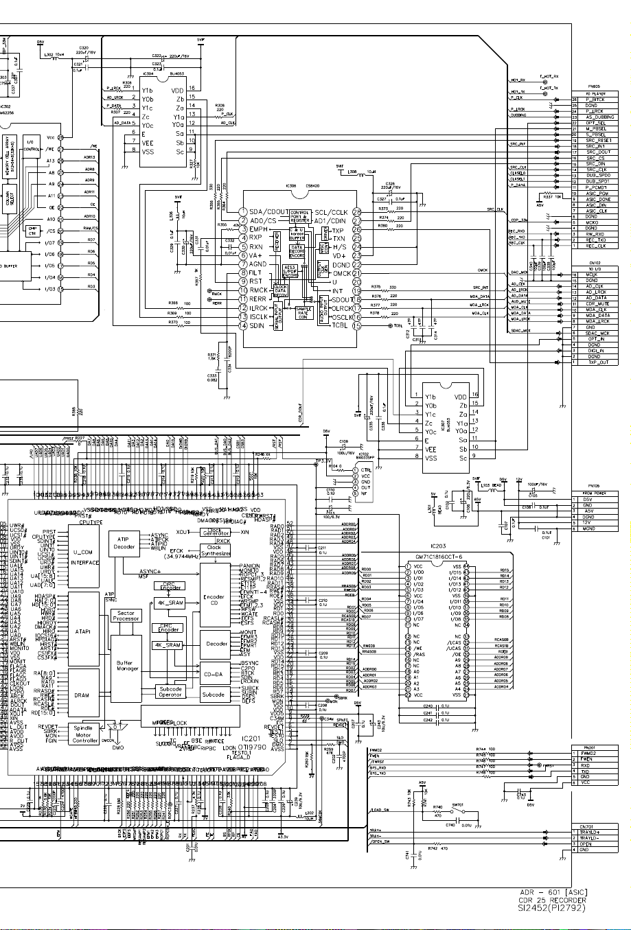
79
CDR20
harman/kardon
Page 80

• AUDIO-SECTION
80
CDR20
harman/kardon
Page 81

• AUDIO-SECTION
81
CDR20
harman/kardon
Page 82

82
CDR20
harman/kardon
Page 83

• FRONT SECTION
83
CDR20
harman/kardon
Page 84

• POWER SECTION
84
CDR20
harman/kardon
Page 85

WIRING DIAGRAM
85
CDR20
harman/kardon
 Loading...