

Page 1
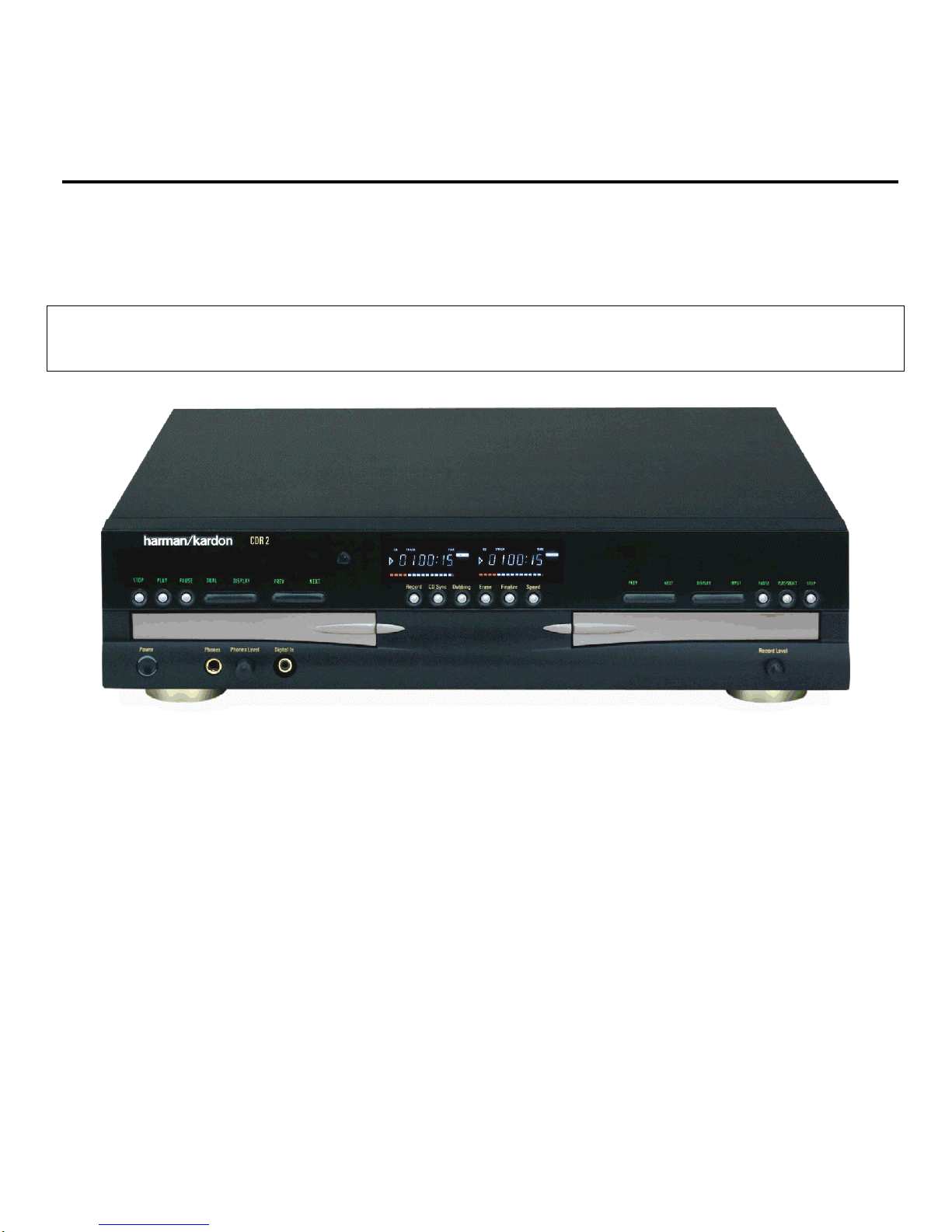
harman/kardon
Model CDR2
Dual Tray CD/CD-R/CD-RW Recorder/Player
SERVICE MANUAL
LASER BEAM SAFETY PRECAUTIONS….…..2
SAFETY PRECAUTIONS...................….…….. 3
CDR2 IMPORTANT NOTES................…..…….4
SPECIFICATIONS .............................….……...6
FRONT PANEL CONTROLS………………. .....7
REAR PANEL CONNECTIONS .. ………….... 11
REMOTE CO NTROL FUNCTIONS……………12
TROUBLESHOOTING GUIDE AND ERROR
MESSAGES....................……………….. …… 14
INTERNAL VIEW ...............................….….....15
DISASSEMBLY PROCEDURES .. …….……..16
IC PINOUTS…….. ..........................…….…… 22
DETAILED TROUBLESHOOTING GUIDE….…37
.
harman/kardon, Inc.
250 Crossways Park Dr.
CONTENTS
BULLETIN 2000-08 Rev2...............….….…....... 66
BULLETIN 2001-008.. ...............……....…… .….. 67
TECH TIP HKTT2001-02 Rev1........…..……......68
TECH TIP HKTT2003-04……..........…..……......69
EXPLODED VIEW/PARTS LIST ..........…......... 70
CD-RECORD MECHANISMS ..........……….......71
BLOCK DIAGRAMS........................….…………73
PCB LAYOUT ....................................................76
EL E CT R I C A L PART S LI ST………….……………82
SCHEMATIC DIAGRAMS ..…………………….. 95
WIRING DIAGRAM ……………………………….115
PACKAGE ..……………………………... …....... 1 16
Woodbury, New York 11797 Rev
1 9/2005
Page 2
LASER BEAM SAFETY PRECAUTIONS
CLASS 1 LASER PRODUCT
CAUTION
Invisible laser radiation when the unit is open.
Do not stare into beam.
CAUTION: USE OF ANY CONTROLS, ADJUSTMENT, OR
PROCEDURES OTHER THAN THOSE SPECIFIED HEREIN
MAY RESULT IN HAZARDOUS RADIATION EXPOSURE.
Do not look directly at the laser beam
coming from the pickup or allow it to
strike against your skin.
This compact disc player uses a pickup that emits a laser beam. The laser beam is emitted from the
location shown in the figure. When checking the laser diode, be sure to keep your eyes at least 1 foot away
from the pickup lens when the diode is turned on. Do not look directly at the laser beam.
CAUTION:
Using controls and adjustment, or doing procedures other than those specified herein, may result in
hazardous radiation exposure.
CDR2 harman/kardon
2
Page 3
SAFETY PRECAUTIONS
This symbol is intended to alert the user to
the presence of uninsulated "dangerous
voltage" within the product's enclosure that
may be of sufficient magnitude to constitute a risk of electric shock to persons.
This symbol is intended to alert the user to
the presence of important operating and
maintenance (servicing) instructions in the
literature accompanying the appliance.
Caution: To prevent electric shock do not use this
(polarized) plug with an extension cord, receptacle or other outlet unless the blades can be
fully inserted to prevent blade exposure.
Attention: Pour prevenir les chocs electriques ne pas
utiliser cetre fiche polarisee avec un
prolongateur, une prise de courant ou une autre sortie de courant, sauf si les lames prevent
etre inserees a fond-sans en laisser aucune
partie a decouvert.
HANDLING LASER PICKUP
The laser diode in the optical system of this player can be damaged by electrostatic discharge from
your clothes or your body. Proper electrostatic grounding for service personal is required during servicing.
BEFORE REPAIRING THE COMPACT DISC PLAYER
Preparation
Human Body Grounding:
Many of the components used in this compact disc player, including the laser pickup, are sensitive to
electrostatic discharge. Service personal should be grounded with an electrostatic armband (1 Mohm).
Caution:
Static charge on clothing does not escape through a body grounding wrist band.
Be careful not to contact the pickup or electrical components with your clothing.
Workbench and Tool Grounding:
A properly-grounded electroconductive plate (1Mohm) or metal sheet should be fitted to the workbench
surface. Tools and instruments (such as soldering irons and scopes) should be grounded to prevent AC
leakage.
Note: Laser diodes are so susceptible to damage from static electricity that, even if a static discharge does
not ruin a diode, it can shorten its life or cause it to work improperly.
WARNING
To prevent fire or shock hazard, do not
expose the unit to rain or moisture.
CDR2 harman/kardon
3
Page 4

CDR2 harman/kardon
4
CDR 2 Important Notes – including issues th at may be
confused with “defects” when they are part of normal
operation
1. ALWAYS remove all discs before moving or repacking the unit! Since the
discs are not seated on a spindle, they have a tendency to slip out of the
trays. At best, the top cover needs to be removed in order to retrieve the
discs. At worst, loose discs inside the chassis can damage delicate
optical parts.
2. DO NOT STARE INTO THE LASER BEAM.
3. Although coaxial digital jacks may look the same as analog RCA jacks,
they are connected to different circuitry which is designed to process a
different type of signal. Do not connect coaxial digital jacks to analog RCA
jacks, and do not use audio interconnects that use twisted pair
construction for coaxial digital connections.
4. All optical connectors are not the same. Make sure to use only “TOS”
type connectors, which will audibly click when fully inserted into the jack.
Remember to save the plastic dust cap for the optical jack, and replace it
when the jack is not in use.
5. When playing CDs in Single mode, the audio signal will be routed to all
output jacks, regardless of which deck of the CDR 2 is playing.
6. The CDR 2 will only record on AUDIO CD-R and CD-RW discs. Only
use discs that bear the “Compact Disc Digital Audio Recordable” or
“Compact Disc Digital Audio ReWritable” logo. The packaging for these
discs should specify that they are intended for use in consumer CD audio
recorders.
7. The CDR 2 will NOT record on discs designed for use in computer CD-R
or CD-RW drives.
8. If a computer CD-R or CD-RW disc has been previously recorded on in a
computer drive and properly finalized in accordance with audio standard
IEC958, it can be played in the CDR 2. However, the CDR 2 will not
erase and record over a computer CD-RW disc.
9. In order to remove a program list, you must either turn the unit off or
remove the disc (or open the drawer so that the CDR 2 thinks you have
removed the disc).
10. Lower the volume when dubbing at high speed. You will be able to hear
the playback, and the higher pitch of the sound at high volumes may
cause damage to your speakers.
11. A program list may only be dubbed at 1x speed. If you attempt to dub at a
higher speed, the CDR 2 will automatically switch to 1x speed.
12. The CDR 2 is equipped with the Serial Copying Management System
(SCMS). This means that you cannot make a digital copy of a digital copy
of a disc; you can only make an analog copy of the first digital copy. If the
disc you are trying to dub is itself a digital copy, or if it contains copy
prohibit signals, the CDR 2 will automatically switch to analog mode. This
will be indicated in the front panel display.
13. The record level control only works in analog mode. If you find the level
control is having an effect on the recording, then the CDR 2 switched into
Page 5

CDR2 harman/kardon
5
analog mode to dub that particular disc. When recording in analog mode,
make sure to use the level control to properly adjust the recording level.
14. In digital mode, if the CDR 2 senses a pause in the signal of more than 3
seconds, it will assume the recording session has ended and stop
recording. This means that if, for example, you program a set of tracks
from different discs on an external CD changer for recording, you may find
that the CDR 2 stops recording after each disc. The CDR 2 is sensing a
delay of more than three seconds while the CD changer switches to a
different disc, and this causes the CDR 2 to end the recording session.
Simply record tracks from one disc at a time on the external changer.
15. In analog mode, the CDR 2 will stop recording after a pause lasting for 10
seconds. If you have pressed the Auto/Manual button to place the unit in
Auto mode, it will increment the track number when it senses a 3 second
pause. In Manual mode, you must increment the track number manually
by pressing either the Track Increment or Next button.
16. The CDR 2 has a convenient front panel digital input for use in recording
from external sources, such as a portable CD player. Since it can only
record from one input at a time, if the CDR 2 senses a signal at both the
front and rear panel inputs, it will automatically record only from the front
panel input.
17. Tracks on a CD-RW disc that has been unfinalized may only be erased in
reverse sequential order. This means that you cannot erase a track in the
beginning or middle of the disc until all of the tracks after it have also been
erased.
18. Unfinalized discs will only play in the record deck, not the play deck.
19. In dual mode, only the output of the play deck will go to headphones.
20. Except when dubbing, make sure to press the Input button to select the
correct source. This is necessary whenever you are recording or using
the CD Sync function with an external source.
21. The pause button will not work while dubbing.
22. The CD Sync feature requires a digital input. Sync recordings may not be
made from an analog source.
For complaint: "CR2 defaults back to X1 speed when attempting a
recording at X4 speed" :
Normal conditions -
1) Will occur when an external input is selected.
2) Will occur when dubbing from a copied CD. (automatically goes into
analog recording)
3) Will occur when dubbing from a copy protected CD. (automatically goes
into analog recording)
4) Will occur when dubbing a programmed play list.
5) Certain CDR disc brands may only copy at X1 speed. Try another brand.
Page 6

CDR2 harman/kardon
6
SPECIFICATIONS
Signal Format
Playback Sampling Frequency 44.1 kHz
D/A Conversion 96kHz, Multi-Bit Delta-Sigma Conversion
Oversampling 128 Times
Playback Specifications
Frequency Response 2Hz – 20,050Hz
Playback S/N 105dB
Playback Dynamic Range 105dB
Playback THD 0.005% / –88dB
Analog Audio Output 2V RMS, ± 2dB
Digital-Coaxial Output 0.5 Vpp/75.
Headphone Output 1V RMS/32. Load
Record Spe cificat ions
Digital Input Sample Rates 32kHz – 96kHz
Recording S/N: Analog 91dB
Recording S/N: Digital Dub Mode Equal to Source
Recording S/N: Digital External Source Source –10dB
Recording Dynamic Range 91dB
Recording THD 0.005% / –85dB
Analog Input Sensitivity 330 mV RMS 47k. = 0dB
Digital Inputs (Direct Recording) 44.1kHz, ±100 ppm/min.
General
Power Requirement 120VAC/60Hz
Power Consumption 48 Watts
Dimensions
Width 17.3"/440mm
Height 4.4"/112mm
Depth 14.2"/363mm
Weight 13.2 lb/6 kg
Page 7
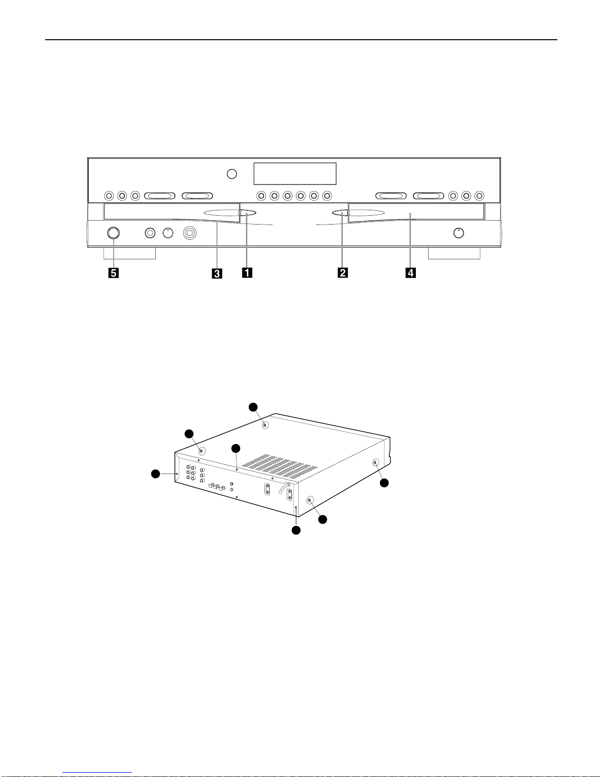
1 Power Switch: Press this switch to apply
power to the CDR 2.When the unit is first
turned on, the Status-Mode Indicator 2
surrounding the switch will turn green. Once
the unit has been turned on with this switch, it
may be operated from either the front panel or
remote control. Press the switch again to turn
the unit completely off.
2 Status-Mode Indicator: When the CDR 2
is in the ON mode,this indicator will glow
green.When the unit has been placed in the
Standby mode by pressing the Power-Off but-
ton on the remote,the indicator will glow
amber, indicating that the unit is still connected
to the AC main supply and is ready to be
turned on from the remote control.
3 Play Deck: This disc deck is used to play
back conventional CD discs and CD-R or
CD-RW discs that have been finalized.
4 Headphone Jack: Connect standard headphones to this jack for private listening.
5 Headphone Level Control: Turn this
control to adjust the volume level to the headphones.Note that the use of this control will
not change the analog output levels at the
rear-panel audio outputs ¡™.
6 Digital Input: This coaxial digital input
may be used to connect a portable digital audio
player to the CDR 2 for digital recording.When
an active digital signal is connected to both the
front- and rear-panel coaxial inputs, the source
connected to the front-panel input will be
selected for recording.
7 Play-Deck Open: Press this button to
open the Play Deck 3.
8 Record Button: Press this button to begin
the recording process.See pages 20-22 for
more information on CD recording.
9 CD Sync: Press this button once to begin
an automated recording of a single track from
an external CD player when a digital connection is used. Press it twice to begin automated
recording of an entire disc. See page 21 for
more information on CD Sync recording.
) Dubbing: Press this button to begin the
process of making a complete copy of the disc
in the Play Deck 3 to a CD-R or CD-RW disc
in the Record Deck %. See page 20 for more
information on dubbing.
! Erase: Press this button to erase one or
more tracks or the entire contents of an unfinalized CD-RW disc.When a CD-RW disc has
already been finalized you may erase the entire
disc or you may “unfinalize”the disc by erasing
the TOC data. See page 22 for more information on erasing CD-RW discs.
Front-Panel Controls
1 Power Switch
2 Status-Mode Indicator
3 Play Deck
4 Headphone Jack
5 Headphone Level Control
6 Digital Input
7 Play-Deck Open
8 Record Button
9 CD Sync
) Dubbing
! Erase
@ Finalize
# Speed
$ Record-Deck Open
% Record Deck
^ Analog-Record Level Control
& Record-Deck Stop
* Record-Deck Play/Select
( Record-Deck Pause
Ó Record-Deck Next
Ô Record-Deck Previous
Input Select
Ò Record-Deck Display Select
Ú Information Display
Û Remote Sensor
Ù Play-Deck Display Select
ı Dual-Play Selector
ˆ Play-Deck Next
˜ Play-Deck Previous
¯ Play-Deck Pause
˘ Play-Deck Play
¸ Play-Deck Stop
2
1
3
5
6
7
8
9
)
!
@
#
$
%
^
4
&
*
(
Ó
Ô
Ò
Ú
Û
Ù
ı
ˆ
˜
¯
˘
¸
CDR2 harman/kardon
7
32
Page 8

Front-Panel Controls
@ Finalize: Press this button when a record-
ing is complete to initiate the finalization
process.The Play/Select Button *j
must be pressed within three seconds to activate finalization.Until this button is pressed
and the finalization process is complete,CD-R
discs may not be played on conventional CD
machines.See page 22 for more information on
finalization.
# Speed: Press this button to select the
recording speed for internal dubs.See page 20
for more information on selecting the proper
speed.
$ Record-Deck Open: Press this button to
open the Record Deck %.
% Record Deck: This Disc Deck is used to
play back CD,CD-R and CD-RW discs;it is also
used for recording CDs.
^ Analog-Record Level Control: The con-
trol is used to adjust the input level when making recordings from analog sources such as cassettes,or when CDs are recorded in an analog
mode.See page 21 for more information on
record levels.
& Record-Deck Stop: Press this button to
stop the CD in the Record Deck.
* Record-Deck Play/Select: This button
has two functions.It may be pressed when a
standard CD is in the Record Deck to put the
machine in play,or it may be used to enter a
selection or start certain record functions.
( Record-Deck Pause:When the Record
Deck is in the Play mode,pressing this button
will pause the disc. If the disc has previously
been paused, pressing this button will restart
the playback.
Ó Record-Deck Next: This button has two
functions.When a disc is playing in the Record
Deck %, press and hold this button to play the
disc in a fast-forward mode to quickly locate a
desired passage.At any time, tapping the button and quickly releasing it will move to the
next track on a disc in play,or enter the track
for programming or play when the disc is
stopped. Once a track is entered,it may
be played by simply pressing the Play
button
*h.
Ô Record Deck Previous: This button has
two functions.When a disc is playing in the
Record Deck %, press and hold this button to
play the disc in a fast reverse mode to quickly
locate a desired passage.At any time, tapping
the button and quickly releasing it will move to
the beginning of the current track,and the next
press will move to the previous track.When a
disc is stopped, each press will move back one
for programming or play when the disc is
stopped. Once a track is entered,it may be
played by simply pressing the Play
button *h.
Input Select: Press this button to select
the input source (analog, digital coax or digital
optical) for recording. See page 21 for more
information on input selection.
Ò Record-Deck Display Select: Press this
button to cycle through the time display options
for the Record Deck. See page 17 for more
information on the time display.
Ú Information Display: The indicators in
the Information Display provide status reports
on the operation of the CDR 2.See page 7 for
complete explanations of each indicator.
Û Remote Sensor: The IR sensor that
receives the commands from the remote control
is behind this area. Do not cover or obscure this
part of the front panel to avoid any malfunction
with the remote.
Ù Play-Deck Display Select: Press this but-
ton to cycle through the time display options
for the Play Deck. See page 17 for more information on the time display.
ı Dual-Play Selector: Press this button to
enable both CD Decks to playback at the same
time and function as separate,independent CD
units.In this mode it is also possible to record
from an external source while the Play Deck is
functioning as a standard CD player. See page
17 for more information on dual-play capability.
ˆ Play-Deck Next: This button has two
functions.When a disc is playing in the Play
Deck 3, press and hold this button to play the
disc in a fast-forward mode to quickly locate a
desired passage.At any time, tapping the button and quickly releasing it will move to the
next track on a disc in play,or enter the track
for programming or play when the disc is
stopped. Once a track is entered,it may be
played by simply pressing the Play
button ˘h.
˜ Play-Deck Previous: This button has two
functions.When a disc is playing in the Play
Deck 3, press and hold this button to play the
disc in a fast-reverse mode to quickly locate a
desired passage.At any time, tapping the button and quickly releasing it will move to the
beginning of the current track,and the next
press will move to the previous track.When a
disc is stopped, each press will move back one
for programming or play when the disc is
stopped. Once a track is entered,it may be
played by simply pressing the Play
button ˘h.
¯ Play-Deck Pause:When the Play Deck is
running, pressing this button will pause the
disc. If the disc has previously been paused,
pressing this button will restart the playback .
˘ Play-Deck Play: Press this button to begin
playback of a CD in the Play Deck or the dubbing process.
¸ Play-Deck Stop: Press this button to stop
the CD in the Play Deck.
CDR2 harman/kardon
8
Page 9
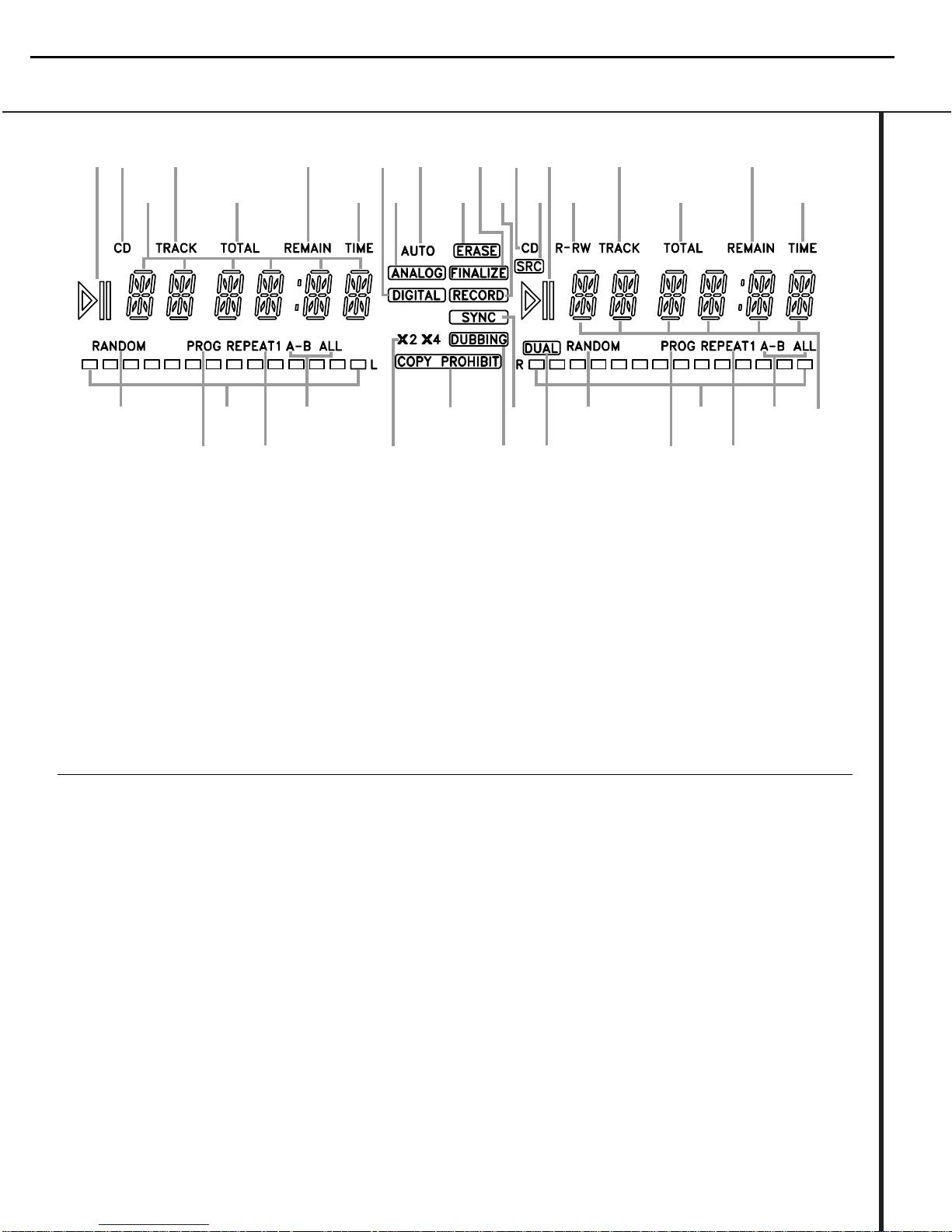
Front-Panel Information Display
A
C
U
W
D
B
E
F
G
I
H
A
J
K
L
M
N
O
L
M
N
O
P
QQ
R
S
S
T
V
X
Y
K
C
D
B
E
A Random Indicators
B Program Indicators
C Level Indicators
D Repeat Indicators
E Repeat-Status Indicators
F Speed Indicators
G Copy-Prohibit Indicator
H Dubbing Indicator
I Sync Indicator
J Dual-Play Indicator
K Information Displays
L Time Indicators
M Remaining-Time Indicators
N Total-Time Indicators
O Track-Time Indicators
P R/RW Indicator
Q Play/Pause Indicators
R Sample-Rate Converter
S CD Indicators
T Record Indicator
U Finalize Indicator
V Erase Indicator
W Auto Indicator
X Analog Indicator
Y Digital Indicator
A Random Indicators: These indicators light
when random playback has been programmed
for one of the CD decks.See page 16 for more
information on random play.
B Program Indicators: These indicators
light when one of the CD decks is being programmed for playback options.See page 16 for
more information on programmed play.
C Level Indicators: These LEDs display the
input level during an analog recording, and the
output level during playback. See page 21 for
more information on record levels.
D Repeat Indicator: This indicator lights
when a repeat function is being used. See page
18 for more information on repeat play.
E Repeat-Status Indicator: These indica-
tors display the type of repeat function being
used. See page 18 for more information on
repeat status.
F Speed Indicators: These indicators show
which record speed has been selected for dub
recordings.See page 20 for more information
on record-speed selection.
G Copy-Prohibit Indicator: This indicator
lights when a recording is not possible
due to the intervention of the Serial Copy
Management System (SCMS). See page 20 for
more information on SCMS.
H Dubbing Indicator: This indicator lights
when a dub is in progress between the two CD
Decks.See page 20 for more information on CD
dubbing.
I Sync Indicator: This indicator lights when
the unit has been programmed for a CD Sync
recording. See page 21 for more information on
CD Sync recordings.
J Dual Play Indicator: The indicator lights
when the unit is playing in the Dual mode,
which allows both CD Decks to act as playback
decks at the same time.See page 17 for more
information on the dual-play mode.
K Information Display: This display serves
two functions,showing the time displays for
discs playing, as well as displaying messages
about discs or recordings.
Important Note: Since the CDR 2 is a dual-deck player/recorder,there are two separate sets of indicators for the Random,Program, Repeat, Repeat
Status,Time,Total Time and Track Time. In addition, there is a separate Information Display,Play/Pause Indicator and CD Indicator for each deck.As the
function of these indicators is identical for both decks,they are described in this manual with a common letter.When the CDR 2 is playing or recording a
disc, any indicators that light on the left side of the display describe to the status of the Play Deck, while those that light on the right side of the display
describe the status of the Record Deck. Depending on the activity of the unit and the settings you select, different indicators may light on the two sides at
the same time.
CDR2 harman/kardon
9
Page 10

L Time Indicator: This indicator lights in con-
junction with one of the time indicators OPQ
to show which of the time status modes is
active.
M Remaining-Time Indicator: This indicator
lights when the Information Display K shows
the time remaining on a disc.
N Total Time:This indicator lights when the
Information Display K shows the total time of
all tracks on a disc.
O Track Time:This indicator lights when the
Information Display K shows the running time
of the individual track being played.
P R/RW Indicator: This indicator shows which
type of recordable disc is present in the Record
Deck %.When a CD-R disc is present,only the
R is lit.The RW lights when an erasable CD-RW
disc is in use.
Q Play/Pause Indicator:These indicators
show the status of the individual CD Decks.The
››
›› lights when the CD is playing, and the
››
››
±±
lights when the unit is in a Pause mode.
R Sample-Rate Converter: This indicator
lights when the Sample-Rate Converter is in use
to change the digital sample rate when the
incoming signal is not the standard 44.1kHz
used by standard CDs.This is an automatic function and does not require any user intervention.
S CD Indicator: This indicator lights when a
standard CD is playing in either deck 3 or %.
T Record Indicator: This indicator lights
when the unit is making a recording and flashes
during the preparations for recording.
U Finalize Indicator: This indicator lights
when the unit is in the Finalization process,
which is required before a CD-R disc may be
played on a standard CD machine.See page 22
for more information on Finalization.
V Erase Indicator: This indicator lights when
a CD-RW disc is being erased.Note that only
CD-RW discs may be erased;it is not possible to
erase a CD-R disc.See page 22 for more information on erasing discs.
W Auto Indicator: This indicator lights when
the automatic method of incrementing tracks is
selected for a recording session.
X Analog Indicator: This indicator lights
when an analog source is being recorded.
See page 20 for more information on source
selection.
Y Digital Indicator: This indicator lights when
an digital source is being recorded. See page 20
for more information on source selection.
CDR2 harman/kardon
10
Page 11
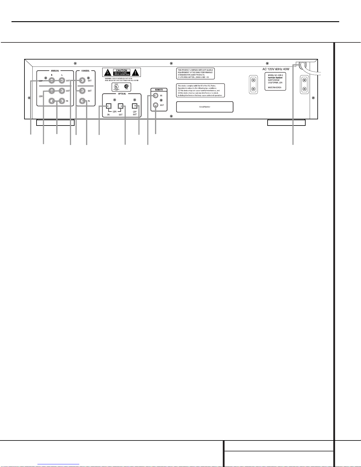
Rear-Panel Connections
¡
™
£
¢
∞
§
¶
•
ª
‚
⁄
¤
¡ Play (CDP)-Deck Analog Output
™ Record (CDR)-Deck Analog Output
£ Record (CDR)-Deck Analog Input
¢ Play (CDP)-Deck Coaxial-Digital Output
∞ Record (CDR)-Deck Coaxial-Digital Output
§ Record (CDR)-Deck Coaxial-Digital Input
¶ Record (CDR)-Deck Optical-Digital Input
• Record (CDR)-Deck Optical-Digital Output
ª Play (CDP)-Deck Optical-DIgital Output
‚ Remote IR Input
⁄ Remote IR Output
¤ AC Power Cord
¡ Play (CDP)-Deck Analog Output:These
jacks carry the analog audio output signal from
the Play Deck 3. Connect them to the CD
input jacks on a receiver, preamp or processor.
™ Record (CDR)-Deck Analog Output:
These jacks carry the output signal from the
Record Deck %. Connect them to the Tape
Play/In input jacks on a receiver,preamp or
processor.
£ Record (CDR)-Deck Analog Input:These
jacks accept the analog signals that are used
for CD recordings.Connect them to the Tape
Rec/Play outputs on a receiver, preamp or
processor.
¢ Play (CDP)-Deck Coaxial-Digital
Output: This jack carries the digital-audio out-
put signal from the Play Deck 3. Connect it
to a coaxial-digital input on a receiver, processor or digital decoder.
∞ Record (CDR)-Deck Coaxial-Digital
Output: This jack carries the digital audio out-
put signal from the Record Deck %. Connect
it to a coaxial digital input on a receiver,
processor or digital decoder.
§ Record (CDR)-Deck Coaxial-Digital
Input: This jack accepts the digital-audio input
signal from a compatible digital audio product
and should be connected directly to a digital
player or to a coaxial-digital output on a CD or
DVD player or an A/V receiver or processor.
IMPORTANT NOTE:The coaxial digital inputs
should only be connected to digital input or
output jacks.Even though they use the same
RCA type connector as standard analog audio
connections,DO NOT connect them to conventional analog input or output jacks.
¶ Record (CDR)-Deck Optical-Digital
Input: This jack accepts the digital-audio input
signal from a compatible digital audio product,
and should be connected directly to the opticaldigital output on a CD or DVD player or an A/V
receiver or processor.
• Record (CDR)-Deck Optical-Digital
Output: This jack carries the digital audio out-
put signal from the Record Deck %. Connect
it to an optical digital input on a receiver,
processor or digital decoder.
ª Play (CDP)-Deck Optical-Digital
Output: This jack carries the digital audio out-
put signal from the Play Deck 3. Connect it
to an optical-digital input on a receiver, processor or digital decoder.
‚ Remote IR Input: Connect the output of a
remote infrared sensor or the remote control
output of another compatible Harman Kardon
product to this jack.This will enable the remote
control to operate even when the front-panel
Remote Sensor Û is blocked.This jack may
also be used with compatible IR remote control
based automation systems.
⁄ Remote IR Output: Connect this jack to
the IR input jack of another compatible Harman
Kardon remote controlled product to have the
built-in remote sensor Û on the CDR 2 provide IR signals to other compatible products.
¤ AC Power Cord: Connect this plug to an
AC outlet.If the outlet is switch controlled,
make certain that it is in the ON position.
CDR2 harman/kardon
11
Page 12
●
●
●
●
●
●
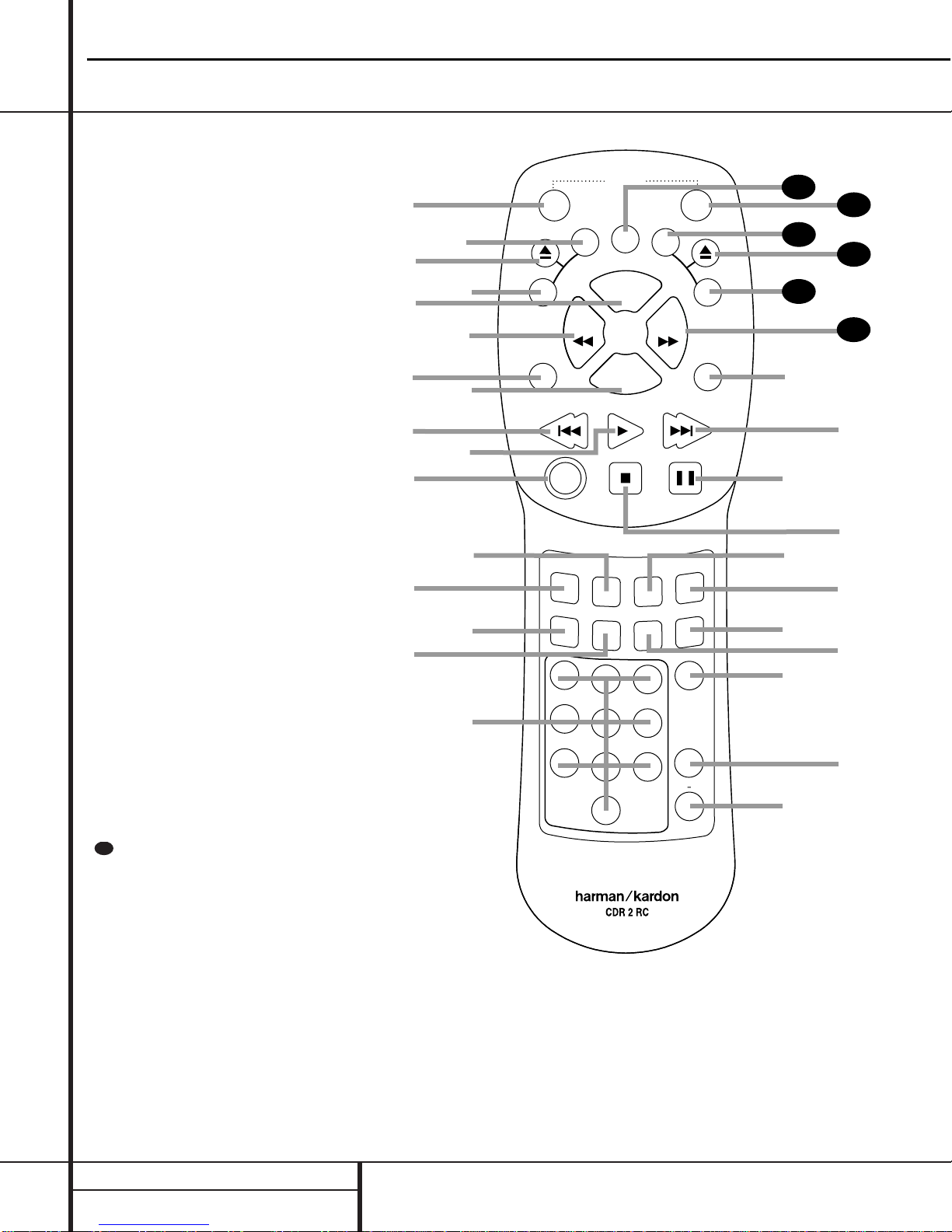
Remote Control Functions
a Power-On Button
b Play (CDP)-Deck Display Control
c Play (CDP)-Deck Open
d Play (CDP)-Deck Select
e Program
f Reverse Search
g Single
h Program Check
i Previous-Track Skip
j Play/Select
k Random Play
l Dub
m Automatic/Manual Track Increment Selector
n Track Increment
o Finalize
p Numeric Keys
q A-B Repeat
r Repeat
s Speed Select
t Record Button
u Erase Button
v Input Select
w CD Sync
x Stop
y Pause
z Next Track
` Dual Playback
28
Forward Search
29
Record (CDR)-Deck Select
30
Record (CDR)-Deck Open
31
Record (CDR)-Deck Display Control
32
Power Off
33
Clear
34
IMPORTANT NOTE:Some of the remote’s
functions including Play,Pause,Stop,
Search, Next and Previous Track,are
shared between the two decks.Always
remember the press the CDP Select button d to use the remote to control the
Play Deck, or press the CDR Select button
to control the Record Deck.
CDR2 harman/kardon
12
29
a
c
e
g
i
k
m
o
b
d
f
h
j
l
n
p
ON
P
D
C
SINGLE
AUTO/MAN
TR INCR
PREV
RANDOM
Y
A
L
P
S
I
D
SEARCH
PLAY/SELECT
DUB
FINALIZE
1
4
7
CDR/RW
POWER
S
I
D
CLEAR
PROG.
PROG
CHECK
STOP PAUSE
CD SYNC
23
5
8
0
P
SEARCH
REC
6
REPEAT
9
OFF
L
A
Y
NEXT
INPUT
ERASE
SPEED
A B
DUAL
33
32
31
30
C
D
R
29
28
`
z
y
x
w
v
u
t
s
r
q
Page 13

Remote Control Functions
a Power-On Button:Press this button to
turn the CDR 2 on. Note that in order for this
control to function, the Front-Panel Power
Switch 1 must first be pressed so that the
unit is in the Standby mode.
b Play (CDP)-Deck Display Control: Press
this button to cycle through the various time
display options for the disc in the Play Deck
3. See page 17 for more information on timedisplay options.
c Play (CDP)-Deck Open: Press this button
to open the Play Deck 3.
d Play (CDP)-Deck Select: Press this but-
ton to control or program the functions of the
disc in the Play Deck 3.
e Program: Press this button to begin the
programming sequence for one of the CD
decks.See page 18 for more information on
programming the CDR 2.
f Reverse Search: Press this button to play
the selected disc in reverse to locate a desired
passage.
g Single: When this button is pressed, the
CDR 2 will function as a two-disc CD player/
changer. In the Single mode,the audio output
will be routed to all output jacks ¡™¢∞
•ª regardless of which CD deck is actually
playing. See page 17 for more information on
the Single-Play mode.
h Program Check: Press this button to
check or edit a programmed playback sequence.
See page 18 for more information on programmed
playback.
i Previous-Track Skip:Press this button to
skip backwards to the beginning of the track
currently being played. Press it a second time to
move back to the beginning of each previous
track.
j Play/Select: This button has two func-
tions.It will most often be used as a standard
play button, but when setting up certain record
functions,it is also used as an Enter or Select
button.
k Random Play: When the CD Deck is
stopped, press this button to begin random play
of all tracks on a disc.
l Dub: Press this button to begin a dub.See
page 20 for more information on dubbing.
m Automatic/Manual Track Increment
Selector: Press this button to select between
automatic and manual track increments during
a recording session. See page 20 for more information on track increments.
n Track Increment:When the Manual
mode for track increments is selected during
recording, press this button to increase the
track number.NOTE:This function does not
operate during CD Sync or dub recording.
o Finalize: Press this button when a record-
ing is complete to initiate the finalization
process.The Play/Select button *j must
be pressed within three seconds to activate
finalization. Until this button is pressed and the
finalization process is complete,CD-R discs
may not be played on conventional CD
machines.See page 22 for more information
on Finalization.
p Numeric Keys: Press these buttons to
access a specific track for playback or during
the programming process.See page18 for more
information on programmed playback.
q A-B Repeat: Press this button to specify a
segment of a disc for repeat play.See page 18
for more information on repeat play.
r Repeat: Press this button once to repeat
the current track.To repeat an entire disc, press
the button twice.
s Speed Select: Press this button to select
the recording speed for internal dubs.See page
20 for more information on selecting the proper
speed.
t Record Button: Press this button to
begin a manual recording.
u Erase Button: Press this button to initiate
the erasure of a track or of an entire CD-RW
disc or to Unfinalize a disc. Note that erasure is
only possible on CD-RW discs.See page 22 for
more information on erasing discs.
v Input Select: Press this button to select
the input source (analog, digital-coax or digitaloptical) for recording. See page 20 for more
information on input selection.
w CD Sync: Press this button once to begin
an automated recording of a single track from
an external CD player when a digital connection
is used. Press it twice to begin automated
recording of an entire disc. See page 21 for
more information on CD Sync recording.
x Stop: Press this button to stop playback or
recording.
y Pause: Press this button to momentarily
pause playback. Press it again to resume
playback.
z Next Track: Press this button to skip
forward to the next track on a disc.
` Dual Playback: Press this button to
enable both CD Decks to play back at the same
time and function as separate,independent CD
units.In this mode it is also possible to record
from an external source while the Play Deck is
functioning as a standard CD player. See page
17 for more information on dual-play capability.
Forward Search: Press this button to
play a disc in a fast-forward mode.
Record (CDR)-Deck Select: Press this
button to control or program the functions of
the disc in the Record Deck %.
Record (CDR)-Deck Open: Press this
button to open the Record Deck %.
Record (CDR)-Deck Display Control:
Press this button to cycle through the various
time-display options for the disc in the Record
Deck %. See page 17 for more information on
time-display options.
Power-Off: Press this button to place the
unit in a Standby mode.
Clear: Press this button to clear an item
in a program sequence.See page18 for more
information..
33
32
31
30
29
28
CDR2 harman/kardon
13
Page 14

Troubleshooting Guide and Error Messages
TROUBLE SHOOTING GUIDE
SYMPTOM POSSIBLE CAUSE SOLUTION
Unit does not operate when Standby switch • No AC power • Make certain AC power cord is plugged into a live outlet.
or remote Power-On is pressed • Check to see if AC outlet is switch controlled.
• Main Power Switch is off • Turn on Main Power
Remote does not function • Wrong deck selected • Press the CDP button to control the Play Deck;
press the CDR button to control the Record Deck
• Dead batteries • Replace both batteries
• Sensor blocked • Remove obstructions from front panel or
connect a remote sensor to the Remote-In Jack
Disc does not erase • CD-R disc in use • CD-R discs do not erase.Use a CD-RW disc
Recorded CD-R disc does not play in • CD-R disc not finalized • Finalize the CD-R disc in the CDR 2’s Record Deck
another CD player or DISC ERROR (see page 22)
message appears in Play Deck
Recording suddenly stops • Input source stopped or paused • Recordings will always stop when the input source
is paused for more than 3 seconds for digital recordings
and 10 seconds for analog recordings
ERROR MESSAGES
ERROR MESSAGE EXPLANATION AND PROBABLE CAUSE SOLUTION
CHECK DISC • A record-related button has been pressed when a • Unfinalize the disc to add tracks to a CD-RW disc
Finalized disc is in the Record Deck % • Replace the disc with a blank CD-R or CD-RW disc
• A record-related button has been pressed when a • Replace the disc with a blank CD-R or CD-RW disc
standard CD is in the Record Deck %
DATA DISC • A non-audio CD-ROM or a CD-Video disc has been • Only CD Audio and DTS discs will play in the CDR 2;
placed in the machine replace the disc
DISC ERROR • An Unfinalized disc has been placed in the Play Deck 3 • Finalize the disc (see page 22)
• ADVDdisc has been placed in the unit • Replace the disc. The CDR2 does not play or dub DVD discs
DISC FULL • There is not enough time left on the disc to complete • Use another blank CD-R or CD-RW disc
a planned recording • Erase one or more tracks on a CD-RW disc
ERROR • The dsic is not seated properly • Open the drawer and check to see that the disc is properly seated
• There is a problem with the disc • Try another disc
FAILED • A dub has not been completed properly • Check the play disc
• Repeat the dub process
FULL • More than 20 tracks have been programmed • Clear all programmed tracks over 20 (see page 18)
NO AUDIO • Arecord-related button has been pressed when • Replace the disc with a blank CD-R or CD-RW Audio disc
a non-audio disc is in the Record Drawer %
SVC-1 • There is an internal problem with the CDR 2 • Contact an authorized Harman Kardon service depot
CDR2 harman/kardon
14
Page 15
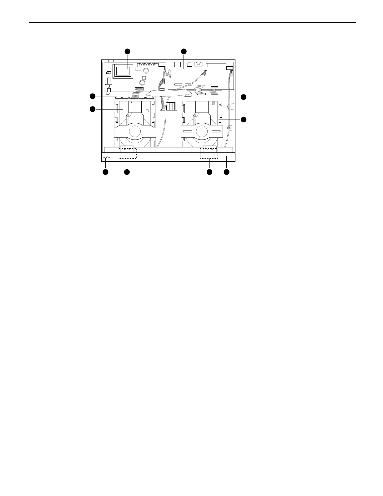
INTERNAL VIEW
●
TOP VIEW
810 9 7
4
6
21
5
3
POWER P.C. BOARD (PCB-1)
IO P.C. BOARD (PCB-2)
CDP MECHANISM ASSY (MECHA-1)
CDR MECHANISM ASSY (MECHA-2)
CDP P.C. BOARD (PCB-3)
CDR P.C. BOARD (PCB-4)
FRONT P.C. BOARD (PCB-5)
HEADPHONE P.C. BOARD (PCB-6)
REC VOLUME P.C. BOARD (PCB-7)
POWER LED P.C. BOARD (PCB-8)
➊
➋
➌
➍
➎
➏
➐
➑
➒
➓
CDR2 harman/kardon
15
Page 16
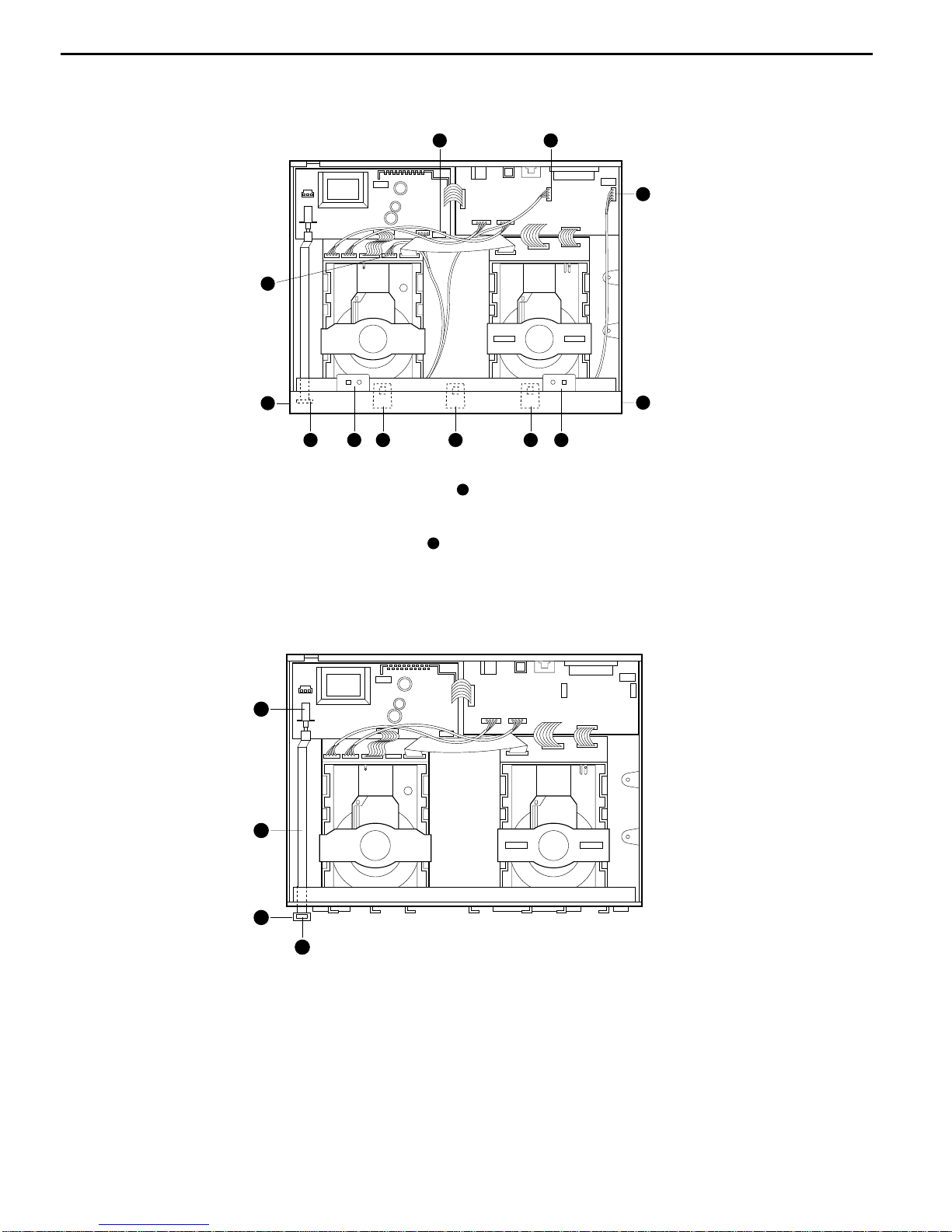
DISASSEMBLY PROCEDURES
1. PCB-(POWER SWITCH) REMOVAL
1. Power on and press open buttons and in Fig.1
2. Remove the CD Door and by pulling it toward you gently.
<Fig 1>
<Fig 2>
2. CABINET TOP REMOVAL
2
7
1
5
3
4
6
1. Remove screws to in Fig.2, and then remove the cover
by sliding it to its rear a little.
2. Remove the cabinet top.
➊
➊➐
➋
➌➍
CDR2 harman/kardon
16
Page 17
4. POWER LEVER ASSEMBLY REMOVAL
1. Pull-out the Power Lever assembly( ) from Power Switch on the PCB-1.
2. Pull-out the Power Knob assembly( ) from the power Lever( )
3. Remove the PCB-8(Power LED ) from the Power Knob assembly( )
2
1
3
4
3. FRONT PANEL ASSEMBLY REMOVAL
5112 76 2
4
8
910
11
3
1. Detach the connector to in Fig.3
2. Remove the front panel by hook-off to in Fig.3 and
pulling it toward you gently.
3. Detach the connector
<Fig 3>
<Fig 4>
➊
➌➊
➍➌
➊
➊➐
12
11
CDR2 harman/kardon
17
Page 18
7
3
6
9 10
8 5
1
4
2
7 15 14 13
1
2
12
8
11
3
10 9
6
4
5
5. PCB-1(Power) REMOVAL
6. PCB-2(I/O) REMOVAL
1. Detach the connector to in Fig.5
2. Remove screws to in Fig.5, and then remove PCB-1.
1. Detach the connector to in Fig.6
2. Remove screws to in Fig.6, and then remove PCB-2.
<Fig 5>
<Fig 6>
➊➍
➎
➊➌
➍➓
15
CDR2 harman/kardon
18
Page 19
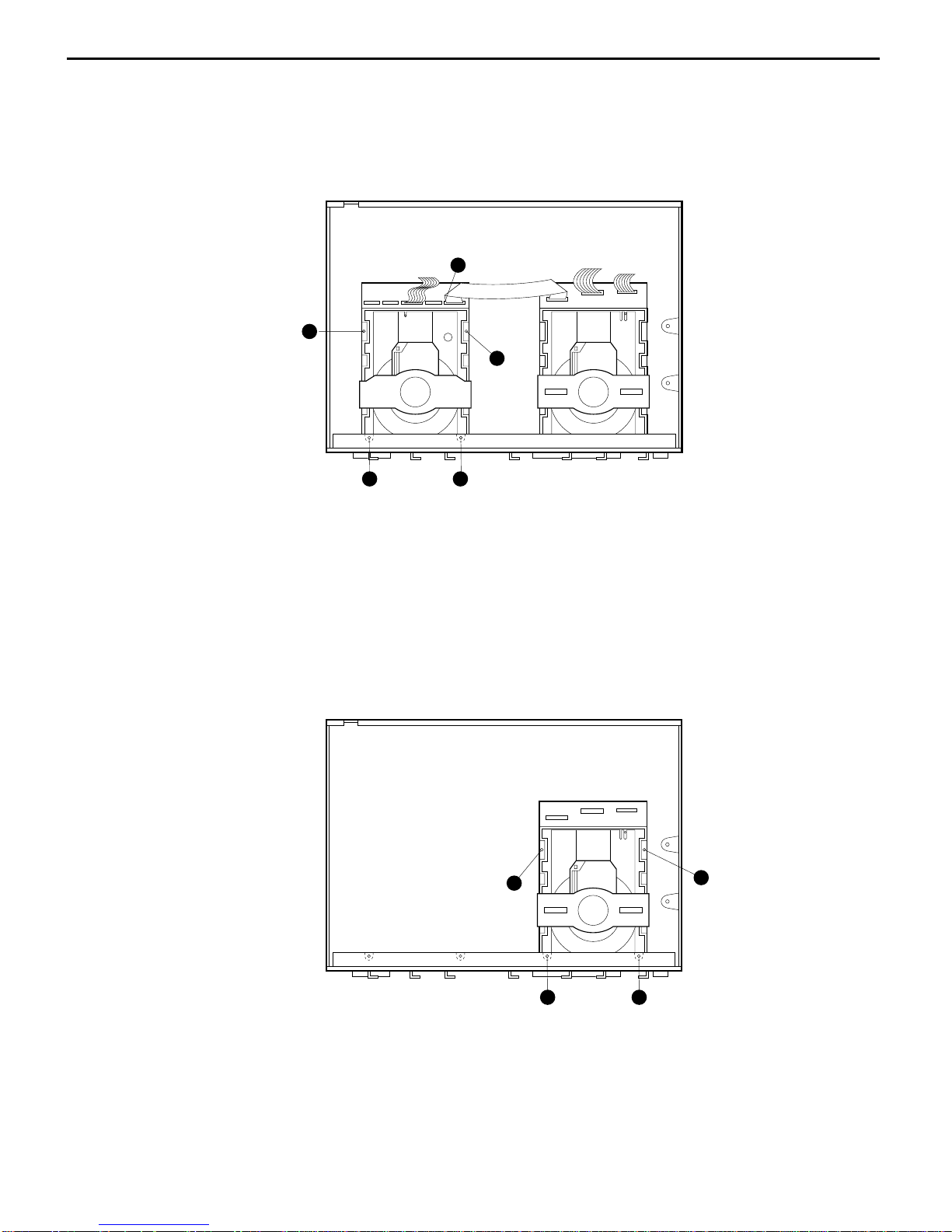
7. MECHA-1 (CDP) ASSEMBLY REMOVAL
8. MECHA-2 (CDR) ASSEMBLY REMOVAL
1
5
2
43
2
43
1
1. Remove screws to in Fig.7
2. Detach the connector in Fig.7, and the remove the Mecha-1.
1. Remove screws to in Fig.8
2. Remove the Mecha-2 and Cover Deck at the same time.
<Fig 7>
<Fig 8>
➊➍
➎
➊➍
CDR2 harman/kardon
19
Page 20
9. PCB-5 (Front) REMOVAL
1. Remove screws to in Fig.9
2. Pull-out the PCB-5 from the Front Panel.
10. PCB-6(Headphone) Removal.
1. Remove screws to in Fig.9
2. Pull-out the Rotate Volume in Fig.1 from the PCB-6(Headphone).
3. Remove the PCB-6 from the Front Panel.
11. PCB-7(REC Volume) Removal.
1. Remove screws to in Fig.9
2. Pull-out the Rotate Volume in Fig.1 from the PCB-7(REC Volume).
3. Remove the PCB-7 from the Front Panel.
➍
➎➋
➊
➌
➏
➐
<Fig 9>
1. unsolder the motor lead to which are connected to
PCB-3.
2. Pull-out the PCB-3 by hook-off to in Fig.10
from the MECHA-1(CDP)
3. Detach the connector to in Fig.10
4. Remove the PCB-3 from the MECHA-1(CDP).
12. PCB-3(CDP) REMOVAL
<Fig 10>
➊
➎
➐
➏
➋
➍➌
➌➍
➊➋
➎➐
➊➌
➏➐
➏
➍➎
➎
CDR2 harman/kardon
20
Page 21
1. Pull-out the PCB-4 by hook-off to in Fig.11
from the MECHA-2(CDR)
2. Detach the connector to in Fig.11
3. Remove the PCB-4 from the MECHA-1(CDR)
13. PCB-4(CDR) REMOVAL
<Fig 11>
➊
➌
➐
➏
➎
➍
➋
➊
➍➐
➌
CDR2 harman/kardon
21
Page 22
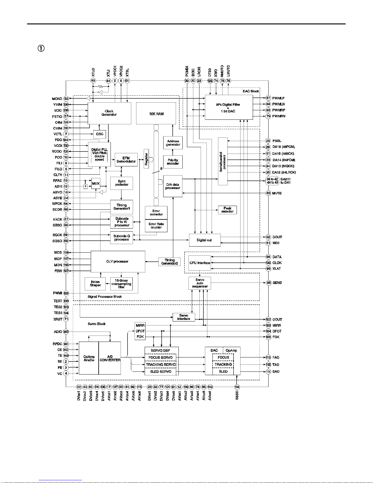
BLOCK DIAGRAM
1. AK8563
➀
Block Diagram
CDR2 harman/kardon
22
Page 23

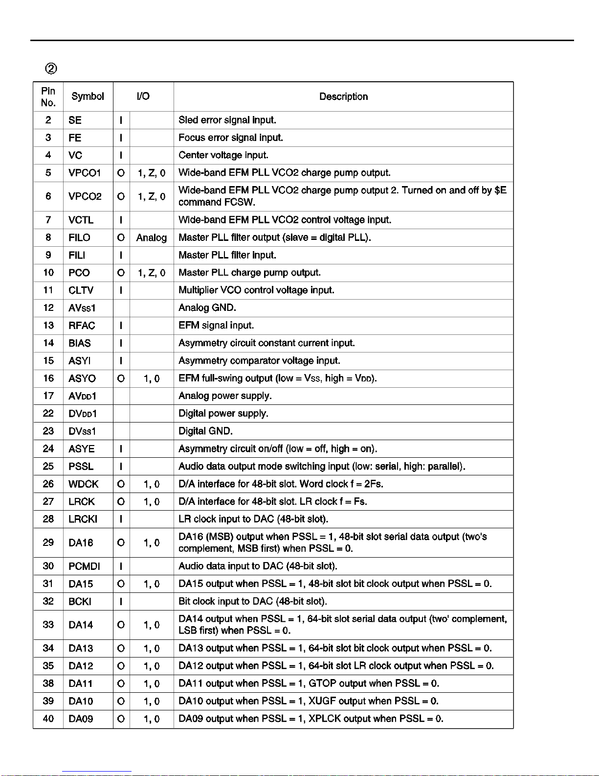
➁ Pin Functions
Pin Number
Designator I/O Functions
1 AVDD3 I Analog Positive Power Source Pin
2 FPDIN I Laser Monitor Diode Contact Pin
3 FVREF I Reference Voltage Level Input Pin for APC
4 FPDO I/O Laser Monitor Output (Connect I/V conversion resistor between
FPDIN)/Laser Monitor Voltage Input
5 WREF I Power Setting Voltage Input for Write APC
6 VWDC O Laser Driver Control Output for Write
7 VWDCN I Laser Driver Control Amp (-) Pin for Write
8 MPP O Main Push-Pull Signal Output
9 TEIN I Input for Tracking Signal Processor
10 TE O Tracking Error Signal Output
11 FE O Focus Error Signal Output
12 BIAS O Bias Resistance Contact Pin. RBIAS=4.7kΩ
13 AGND1 O Decoupling Pin for Internal Reference Voltage
14 VREF I/O
Decoupling Pin for Internal Reference Voltage/Reference Voltage Input Pin
15 NC(VSS) 16 XLAT I Latch Input for Register Settings
17 SDATA I Data Input for Register Settings
18 SCLK I Clock Input for Register Settings
19 MCLK I Main Clock Input (34.5744 MHz)
20 DVSS I Digital Ground Pin
21 DVDD I Digital Positive Power Source Pin
22 ATFG O ATIP FG Output (Wobble
Signal
after binary Operation)
23 XTOR O Tracking Amplitude Detection Output
24 XTAND O Off-Track Detection Output
25 TZC O Tracking Zero-Cross Detection Signal Output
26 RECD2 O
Recording Area Detection Signal 2. "H" Recorded Section, "L" Unrecorded
Section
27 RECD1 O
Recording Area Detection Signal 1. "H" Recorded section, "L" Unrecorded
Section
28 RZC O RF Zero-Cross Detection Signal Output
29 DECEFM O EFM Output after Slice (reverse)
30 XDECEFM O EFM Output after Slice (normal rotation)
31 GAINUP3 I 0, +18dB Switch Control Input Pin. "H" +18dB, "L" 0dB
32 GAINUP2 I 0, +18dB Switch Control Input Pin. "H" +18dB, "L" 0dB
33 GAINUP1 I 0, +18dB Switch Control Input Pin. "H" +18dB, "L" 0dB
34 SLHOLD I Slice Level Hold Signal Input Pin. "H" Hold
35 MPDSH I Sample Pulse Input for Main Beam Signal. "H" Sample, "L" Hold
36 SPDSH I Sample Pulse Input for Side Beam Signal. "H" Sample, "L" Hold
37 WBLSH I Sample Pulse Input for Wobble Signal. "H" Sample, "L" Hold
38 RFPDSH I Sample Pulse Input for Read APC. "H" Sample, "L" Hold
39 WFPDSH I Sainple Pulse Input for Write APC. "H" Sample, "L" Hold
CDR2 harman/kardon
23
Page 24

Pin Number
Designator I/O Functions
40 AVSS2 I Analog Ground Pin
41 AVDD2 I Analog Positive Power Source Pin
42 XRST I Register Reset Pin. "L" Register Initialization
43 WLDON I Write LD Control Input. "L" Write APC Setting to Zero, "H" LD 0N
44 AGCON I Wobble AGC Enable Input. "H" AGC ON, "L" AGC reset
45 TESTAGC O Test Pin
46 ATFM O Wobble Signal Output
47 AGC1C O External CAP Connector Pin for AGC Response Speed Setting
48 AGC2C O External CAP Connector Pin for AGC Response Speed Setting
49 AGC3C O External CAP Connector Pin for AGC Response Speed Setting
50 AGND2 O Decoupling Pin for Internal Reference Voltage
51 BHO O RRF Signal Bottom Level Output Pin
52 PHO O RRF Signal Peak Level Output Pin
53
TESTEQRFN
O Test Pin
54
TESTEQRFP
O Test pin
55 SLLPFP I LPF Input (+) for Auto Slice
56 SLLPEN I LPF Input (-) for Auto Slice
57 OSTCC O CAP Connector Pin for Equalizer Output Offset Canceller fc
58 WRF O Write RF Signal Output
59 NC(VSS) 60 AVSS1 O Analog Ground Pin
61 AVDD1 I Analog Positive Power Source Pin
62 RECDIN I RF Input for Recording Area Detection
63 RRF O Read RF Signal Output
64 MPXOUT O Multiplexer Output for Signal Monitoring
65 AUX1 I Auxiliary Input Pin for Signal Monitoring (1)
66 AUX2 I Auxiliary Input Pin for Signal Monitoring (2)
67 AUX3 I Auxiliary Input Pin for Signal Monitoring (3)
68 GIN I Side Beam Signal (G) Input
69 HIN I Side Beam Signal (H) Input
70 EIN I Side Beam SignaI (E) Input
71 FIN I Side Beam SignaI (F) Input
72 HAVC I Main • Side Beam Signal Midpoint Voltage Input
73 DIN I Main Beam Signal (D) Input
74 CIN I Main Beam Signal (C) Input
75 BIN I Main Beam Signal (B) Input
76 AIN I Main Beam Signal (A) Input
77 RREF I Power Setting Voltage Input for Read APC
78 VRDCN I Laser Driver Control Amp (-) Pin for Read
79 VRDC O Laser Driver Control Output for Read
80 AVSS3 I Analog Ground Pin
Use NC (unused) pin by connecting to VSS.
CDR2 harman/kardon
24
Page 25
2. RL5E808
➀ Block Diagram
DEFS
RD(15:0)
Subcode if
CD-DA if
RAM if
Clock
Synthesizer
Clock
Generator
ATIP
Decoder
Motor
Speed
Controller
CD
Encoder
Subcode
Operator
CIRC
Encoder
Sector
Processor
SysCon if
DRAM if
ATAPI if
Buffer
Manager
ROEB
RCAS0B
RCAS1B:RWE1B
RWE0B
RRAS0B
RA10:RRAS2B
RA11:RRAS1B
RA9:RRAS3B
RA(8:0)
DASPB
CS3FXB
CS1FXB
DA2
DA0
DIAGB
DA1
IOCS16B
DINT
DACKB
DIORDY
DIORB
DIOWB
DREQ
DD(15:0)
DRSTB
SAD(7:0)
SALE
SA(15:0)
SRDY
SWEB
SREB
CS0B
CS1B
SINT0
SINT1
SRESB
DSFS
SUBIN
SUBCK
LRCKIN
SDIN
BTCK
C2PO
ESFS
EEFS
WGATE
HFSW
PANICIN
EFM1
EFM2
EFMNT1-4
E11TP
E11TS
RESMP
ROPC1
ROPC2
VCOIN
PLLCK
34.5744MHz
XCX
CPOUT
CLKIN
(33.8688MHz)
TON
DEFS
DPLOCK
MPWM
DMCON
MON
FGIN
REVDET
SBRK
WBLIN
ATIPIO
ATIPCK
ASYNC
CDR2 harman/kardon
25
Page 26
4. LA 6543M
3. M56788
➀ Block Diagram
IN1+
Vm1 VBS1
VREFO
VBS2
Vm2
IN3IN3+
OUT3
CH3IN
VM3(+)
VM3(-)
VM4(+)
VM4(-)
IN4IN4+
OUT4
VM5(+)
VM5(-)
IN5IN5+
OUT5
SLEEP
CH5
X8
CH4
X8
CH3
X8
Hi:Sleep
MUTE2MUTE1
SS.GND GND(4PIN)
BIAS
1.25V
Low,Open
MUTE ON
Vrefm1
R
R
E3
E4
E5
VBS2
VBS1
VBS2
VBS2
VBS2
VBS2
VBS2
VBS1
VBS1
VBS1
VBS1
Vm1 Vm2
R
R
VBS2
VBS1
Vrefm2
TSD
5CH
1~4
CH
IN1-
OUT1
VM1(+)
VM1(-)
VM2(+)
VM2(-)
OUT2
IN2-
IN2+
VREFO
VREF
REGB
REG+
RF
RF
NC
VSS2
VSS2-OUT
MUTE1
VIN1
VG1
VIN2
VG2
VIN3
VG3
VIN4
V03~V08
V01~V02
MUTE1
CH1(V01~V02)
MUTE2
CH2(VO3~VO4)
CH3(VO5~VO6)
CH4(VO7~VO8)
VG4
MUTE2
VCC
RF
RF
RF
RF
VSS1
VSS1-OUT
VO1
VO2
VS1
VO3
VO4
VO5
VO6
VS2
VO7
VO8
VREF OUT
VREF IN
RF
RF
VREG
VREF
E2
CH1
X5
CH2
X5
E1
➀ Block Diagram
CDR2 harman/kardon
26
Page 27
5. MN12511
➀ Block Diagram
D15~D0
NSDO
V
DD
VSS
VPP
NCE
NSCK
NSDI
CK
CK
OE
OK
R
R
OK
CDR2 harman/kardon
27
Page 28
CDR2 harman/kardon
28
Page 29
CDR2 harman/kardon
29
PIN FUNCTIONS
Page 30
CDR2 harman/kardon
30
Page 31

CDR2 harman/kardon
31
Page 32

CDR2 harman/kardon
32
Page 33

CDR2 harman/kardon
33
Page 34

CDR2 harman/kardon
34
Page 35

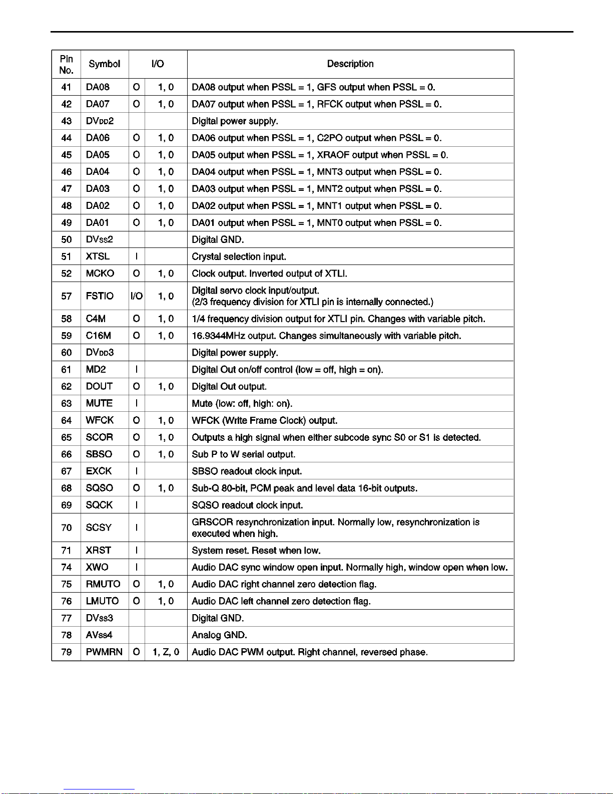
➁ Pin Descriptions
No. Pin Name I/O FUNCTION
1 AINR+ I Right channel analog positive input pin
2 AINR- I Right channel analog negative input Pin
3 VREF O Voltage Reference output pin (VA-2.6V)
Normally connected to VA with a 0.luF ceramic capacitor in
parallel with a 10uF electrolytic capacitor.
4 VA --- Analog section Analog Power Supply, +5V
5 AGND --- Analog section Analog Ground
6 AINL+ I Left channel analog positive input pin
7 AINL- I Left channel analog negative input pin
8 TST1 Test pin (Pull-down pin)
10 TST2 Should be left floating.
11 TST3
14 TST4
9 HPFE I High Pass Filter Enable pin(Pull-up pin)
"H": ON
"L": OFF
12 VD --- Digital section Digital Power Supply pin, +5V
13 DGND --- Digital section Digital Ground pin
16
PD
I Power Down pin
"L" brings tne device into power-down mode. Must be done
once after power-on.
17 MCLK I Master Clock input pin
CMODE="H" : 384fs
CMODE="L" : 256fs
18 SCLK I/O Serial Data Clock pin
Data is clocked out at the falling edge of SCLK.
Slave mode: 64fs clock is input usually.
Master mode: SCLK outputs a 64fs clock.
SCLK stays low during the power-down mode(PD="L").
19 LRCK I/O L/R Channel Clock Select pin
Slave mode: An fs clock is fed to this LRCK pin.
Master mode: LRCK output an fs clock.
LRCK goes "H" at SMODE2="L" and "L" at SMODE2='"H"
during reset when SMODE1 "H".
20 FSYNC I/O Frame Synchronization Signal pin
Slave mode: When "H", data bits are clocked out on SDATA.
As I2S slave mode ignores FSYNC, it should hold "L" or "H".
Master mode: FSYNC outputs 2fs clock.
Stay low during the power-down mode(PD="L")
21 SDATA O Serial Data Output pin
Data are output with MSB first, in 2's complement format.
After 20 bits are output it turns to "L". It also remains "L"at a
power-down mode(PD="L").
CDR2 harman/kardon
35
Page 36

No. Pin Name I/O FUNCTION
22 CMODE I Master Clock Selection pin
"L": MCLK=256fs
"H": MCLK=384fs
23 SMODE1 I Serial Interface Mode Select pin
15 SMODE2 I Defines the directions of LRCK, SCLK and FSYNC pins and
Output Data Format. SMODE2 is pull-down pin.
SMODE1 SMODE2 MODE LRCK
L L Slave mode: MSB justified: :H/L
H L Master mode: Similar to I2S :H/L
L H Slavemode:I2S :L/H
H H Master mode:I2S :L/H
24 VB --- Substrate Power Supply, +5V
9. 74VHC374
➀ Logic Symbol ➁ Connection Diagram
➂ Pin Descriptions
Pin Names Description
D
0-D7
Data Inputs
CP Clock Pulse Input
OE 3-STATE Output Enable Input
O
0-O7
3-STATE Outputs
CDR2 harman/kardon
36
Page 37

TROUBLESHOOTING GUIDE
1. Initial Lead-in Operation
2. Trouble List(Circuit)
(In the Initial Lead-in Operation Mode)
A. Pick-Up doesn’t move to the inner-track.
B. Pick-Up lens doesn’t move up and down.
C. Disc doesn’t rotate.
D. The Laser(RED) of Pick-Up doesn’t light.
E. TOC isn’t read.
CDR2 harman/kardon
37
Page 38

CDR2 harman/kardon
38
Page 39

CDR2 harman/kardon
39
Page 40

CDR2 harman/kardon
40
Page 41

CDR2 harman/kardon
41
Page 42

CDR2 harman/kardon
42
Page 43

CDR2 harman/kardon
43
Page 44

CDR2 harman/kardon
44
Page 45

CDR2 harman/kardon
45
Page 46

CDR2 harman/kardon
46
Page 47

CDR2 harman/kardon
47
Page 48

CDR2 harman/kardon
48
Page 49

CDR2 harman/kardon
49
Page 50

CDR2 harman/kardon
50
Page 51

CDR2 harman/kardon
51
Page 52

CDR2 harman/kardon
52
Page 53

CDR2 harman/kardon
53
Page 54

CDR2 harman/kardon
54
Page 55

CDR2 harman/kardon
55
Page 56

CDR2 harman/kardon
56
Page 57

CDR2 harman/kardon
57
Page 58

CDR2 harman/kardon
58
Page 59

CDR2 harman/kardon
59
Page 60

CDR2 harman/kardon
60
Page 61

CDR2 harman/kardon
61
Page 62

CDR2 harman/kardon
62
Page 63

CDR2 harman/kardon
63
Page 64

●
ASIC
IC 301(
74 ,
105, 107
)
●
BITSTR~1.
IC 301(
80 , 86 , 88
)
107
105
74
80
86
88
CDR2 harman/kardon
64
Page 65

●
U-COM
IC 202(
12 , 14 , 16
)
12 , 14
16
CDR2 harman/kardon
65
Page 66

66
CDR2 harman/kardon
harman/kardon Service Bulletin
Service bulletin # H/K2000-08 Rev3 – September 2005
To: All harman/kardon Service Centers
Models: CDR2
Subject: Complain ts Related To Early Software
In the event you receive a CDR2 with one or more of the symptoms listed below, an upgrade in the
software may be necessary. Confirmation may be made by checking the serial numbers listed below.
1) When dubbing from the CDP deck, the unit randomly skips some of the tracks during the recording process
2) Audio drop out every 15-30 seconds, for less than a second each time, using the analog CDR outputs while
playing a disc in the CDP deck
3) Analog outputs of both wells have glitching/skipping sounds, but when monitored via headphones the sound
is normal
4) Intermittent Recording
5) CDs played on CDP deck have wow & flutter. Wow characterized by a slight hesitation in the sound and
flutter as a rapid fluttering sound
6) CDR deck durin g the reco rding process "chopping off" (truncating) the first few seconds of each track using
digital inputs
7) W ill not SYNCH record with MD player digital connections
8) W ill not SYNCH record with DVD pla y er connections
9) CDR deck when played as normal CD output mutes randomly
10) Switches to norma l (x1) dubbing speed even though x2 or x4 had been selected
11) Jumps to another part of the track dubbing at x4 speed
12) Low music input causes the unit to skip to the next track during recording
13) CDR deck during th e recording process does not automatically set track increments
For additional information and current resources available to perform upgrades, please contact:
Harman Service Technical Support
Phone: 516-682-6435
E-mail: techsupport@harman.com
Model
CDR2
CDR2
CDR2
LG0001-10793 to LG0001-12428
LG0001-14329 to LG0001-14675
LG0001-21381 to LG0001-26340
LG0001-01001 to LG0001-10792
LG0001-12429 to LG0001-14328
LG0001-14676 to LG0001-21380
LG0001-26341 to LG0001-29500
Serial number
120V
LG0001-29501 and above
Serial number
230V
Has early
LG0002-01001 to LG0002-08500
LG0002-08501 and above
Status
software/hardware
version – no
upgrade possible
Has la ter
software/hardware
version
Factory Ins talled
latest ver sion
Action (Upgrade)
NONE POSSIBLE
NONE REQUIRED
UPGRADABLE
NONE REQUIRED
Page 67

67
CDR2 harman/kardon
harman/kardon
Service bulletin # H/K2001-008 November 2001
To: All harman/kardon Service Centers
Model: CDR2
Subject: Mechanical noise from Play section and la ser sled stops.
In the event you receive a CDR2 Player/Recorder with this complaint: “There is a mechanical clicking
noise in the player section, either when the CDR2 turns “ON” or when it starts to play a CD”:
1) Clean and re-grease all the mechanical tracking parts:
2 shafts #028/32, laser #025, guide feed #026 tracking motor #029
Warranty labor rate: MINOR repair
Service Bulletin
CDP section expl oded v iew
2) Change R237 on the CDP board from 470Ω to 180Ω.
Location is next to pin 52 of IC201. 180Ω resistor is h/k part # 6044437091.
Page 68

68
CDR2 harman/kardon
harman/kardon TECH TIPS
Troubleshooting tips and solutions to common service problems
For model: CDR2 TIP# HKTT2001-02 Rev1
Issue: Power Failure During A Recording Session
Power loss is defined as: CDR2 was switched OFF by the POWER button on the front panel, or by the OFF
button on the remote control, or through a power failure.
Circumstance #1
Power loss during the actual recording process
Symptom:
Attempts to read the disc in the Record drawer now produces an ERROR message in the display.
Solution:
Unfortunately, the disc is ruined and there is no way to retrieve this information. When you record a track, the
CDR2 updates the information on the disc so that it can read it even though the disc has not been finalized.
By turning off the unit while recording is in process, the unit never had the opportunity to update the disc. As
a result, the disc is no longer useable.
Circumstance #2
Power loss after the recording process took place, but before finalizing
Symptom:
A CDR with recordings will not finalize after the Finalize and Play/Select select buttons on the remote control
are pressed. Instead, when these buttons are pressed, the CDR (or a CD in the Play drawer) begins to Play -
not Finalize. (However, when the Finalize and Play/Select buttons on the front panel are used, the CDR2 will
finalize the CDR with recordings properly).
Solution:
After turning the CDR2 on, and the unit has read the information from both drawers, press the CDR button on
the remote control and follow the owner’s manuals’ instructions to complete the finalization process.
This problem will not occur when the recording and finalizing "session" are done at the same time, without a
power loss to the CDR2 off in the middle of the session.
Model Serial Numbers
120V
CDR2 All products affected All products affected Power loss during the
Serial Numbers
230V
STATUS ACTION
When recording:
recording session
When recording is complete, but
Press the CDR button on the
remote control before Finalizing
Disc is ruined
before finalizing:
Page 69

69
CDR2 harman/kardon
harman/kardon
Troubleshooting tips and solutions to common service problems
For models: CDR2 TIP# HKTT2003-04
VARIOUS COMPLAINTS - TIPS AND SOLUTIONS
Complaint Of Noisy Recording, Dropout, “Static” Or “Ticking” Sound During Recording: Check Flat Cable
Connecting Record And Play Decks – order part# 6850R-GZ21Z. Also ground cable to chassis
clip or alligator clip)
No Digital Signal Outp ut:
Check T401
Check X501
Units with serial #’s LG0001-8001 (120v) and higher should not have a problem with components.
Check T101
Units with serial #’s LG0001-29501 (120v) and higher should not have a problem with component.
Playability Upgrades:
Remove C121,C222
C104: change from 0.1ohms to 0.015 ohms.
R130: change from 5.6Ω to 8.2Ω.
R312: change from 15Ω to 22Ω.
R310: change from 22Ω to 15Ω.
Units with serial #’s LG0001-29501(120v) and higher have been modified
Digital Signal Output Level
R254,R259 change from 100Ω to 330Ω
R257,R263 change from 330Ω to 100Ω
For complaint: "CR2 defaults back to X1 speed when attempting to record at X4 speed" :
Normal conditions -
1) Will occur when an external input is selected.
2) Will occur when dubbing from a copied CD. (automatically goes into analog recording)
3) Will occur when dubbing from a copy protected CD. (automatically goes into analog recording)
4) Will occur when dubbing a programmed play list.
5) Certain CDR disc brands may only copy at X1 speed. Try another brand.
Otherwise replace IC209.
CDR2 DEAD (NO POWER/SHUTDOWN) AFTER IT WAS MOV ED, SHIPPED, OR DROPPED:
Check for a broken Power Supply traces in PCB area around power transformer.
Units with serial #’s LG0001-10793 (120v) and higher have been modified
TECH TIPS
(with paper
Please check the power supply
soldering. Especially all the
components mounted on the heatsink
Page 70

REF.NO. PART NO DESCRIPTION
1 4940S-6939A KNOB POWER
2 3790S-M079A WINDOW POWER
3 3300S-X002A PLATE PET
4 6871RZ1963A PCB ASSY LED
5 4510S-1019A LEVER POWER
6 3580S-C108A DOOR PLAY
7 3580S-C105A DOOR ACDR
8 6721R-0301A MECHA Q1(PLAYER)
9 4405H-1068C MECHA E2
10 3610S-0192A FOOT BOTTOM
11 3140S-P913B CHASSIS MAIN
12 3790S-M072A WINDOW FL
13 4350S-0001A RING 3 KEY
14 4350S-0002A RING 6 KEY
15 3858S-X170A SHEET FL
16 3720S-M113A PANEL FRONT
17 3858S-X171A SHEET LCD
18 4940S-6938A KNOB PLAY 3K
19 4940S-6937A KNOB SEESAW 4K
20 4940S-6940A KNOB REC 8K
21 4940S-6941A KNOB VOLUME
22 6871RJ1963A PCB ASSY HEADPHONE
23 6871RU0001A PCB ASSY VOLUME
24 6871SF42GAA PCB ASSY FL/KEY
25 6871RP42NAA PCB ASSY POWER
26 6871S-429AB PCB ASSY IO
27 3720S-P014A PANEL BACK
28 3140S-P911C CHASSIS TOP
29 353-046K SCREW(M3)
30 353-633A SCREW(M4)
31 3846S-0208A MARK BADGE
32 6871S-423AB PCB PLAY
33 6871S-42QAA PCB REC
34 4766R-0003A FELT FOOT
35 3550S-1027B COVER-RW DECK
EXPLODED VIEW/PARTS LIST
●
MAIN SECTION
CDR2 harman/kardon
70
Page 71

●
CD PLAY SECTION
REF.NO. PART NO DESCRIPTION
004 4930H-1061A HOLDER ASSY CLAMP(Q1, ACDR)
005 4861R-D004A CLAMP ASSY Q1 & E2 ACDR
006 4931R-0033A HOLDER ASSY CLAMP(Q1, ACDR)
007 3390H-1016C TRAY DISC, BLACK)
008 4400H-1009A BELT GM-RT 1332A
009 4560H-1005A PULLEY MOTER(GM-R512)
010 4470H-115A GEAR LOADING(Q1)
011 4970H-1087A SPRING LEVER SWITCH
012 4510H-1033A LEVER SWITCH(Q1)
013 4680HP-2001A MOTER(MECH) RF-300CH-11440 M/C
014 3040H-1056A BASE UP/DOWN(Q1)
015 3040H-1055A BASE MAIN(Q1)
016 4974H-1034A GUIDE UP/DOWN(Q1)
020 5040H-1053A RUBBER GM-RT1332A(F)
021 5040H-1052A RUBBER GM-RT1332A(R)
025 6716S-E001A PICK UP SF-P151EXVA SANYO ACDR
026 4974H-1039A GUIDE FEED
027 4970H-1086A SPRING FEED
028 4370H-1024C SHAFT P/U
029 4680HP-50028 MOTOR 15S1R10F6NC3 MATSUSHITA STEPPI
030 4680HB-1019A MOTOR GCS-L32A LGEC SPINDLE
032 4370H-1025B SHAFT P/U
033 6850HD-1L16A CABLE, FLEXIBLE 2896-A-1.0-17(05*65)160 BANDO
050 3040H-1057A BASE P/U(Q1)
420 4000H-1006B SCREW + D1.7 4.5MM SWRCH16A/ZNY 4MM
431 1SSXXH-1004A SCREW + D1.7 5MM SWRCH16A/ZNY 3.5MM
434 1SSXXH-1007B SCREW + D2.0 6MM SWRCH16A/ZNBK 4MM 1
435 1SSXXH-1011B SCREW + D1.7 6MM SWRCH16A/NIY 3.5MM
CDR2 harman/kardon
71
Page 72

-
●
CD RECORD SECTION
REF.NO. PART NO DESCRIPTION
5 4861R-0005A CLAMP ASSY ACDR E2(4861H-0008A)
7 3390R-0007A TRAY DISC(E2, 3390H-1011C)
8 4400R-0007A BELT ACDR E2(4400H-1003A)
9 4560R-0009A PULLEY GEAR(E2, 4560H-1004A)
10 4681R-1022A MOTOR ASSY LOADING(E2, 4681H-1024A)
11 4470R-0059A GEAR LOADING(E2, 4470H-1015A)
12 4470R-0060A GEAR MIDDLE(E2, 4470H-1016A)
14 3040R-0030A BASE UP/DOWN(E2, 3040H-1059A)
15 3040R-0029A BASE MAIN(E2, 3040H-1035B)
16 4974R-0028A GUIDE UP/DOWN(E2, 4974H-1023A)
20 5040R-0048A RUBBER FRONT(E2, 5040H-1055A)
21 5040R-0047A RUBBER REAR(E2, 5040H-1054A)
22 4680R-E002A MOTOR(MECH) FEEDING RF-300PA-11400 MABUCHI E2(4680HP4001A)
23 4470R-0065A GEAR PINION(U, E2, 4470H-1123A)
24 4470R-0063A GEAR RACK(B, E2, 4470H-1121A)
25 6716R-E001A PICK UP KRS-200A SONY E2(6716HSW201A)
26 4370R-0033A SHAFT P/U(R/E2, 4370H-1079A)
28 4930R-0194A HOLDER FFC(E2, 4930H-1063A)
29 4370R-0032A SHAFT P/U(L/E2, 4370H-1078A)
30 4810R-0076A BRACKET WEIGHTBALANCER(E2, 4810H-1042A)
31 4680R-C001A MOTOR(MECH) SPINDLE GRS-R01A LGC&D(E2, 4680HB 1025A)
400 1SZZR-0022A SCREW D1.7 5MM SWRCH16A/NIY(E2, 1SZZH-1005A)
402 1SZZR-0020A SCREW D2. 0 4.5MM SWRCH16A/ZNY(E2, 1SZZH-1020C)
418 1SZZR-0014A SCREW D1. 7 7MM SWRCH16A/ZNY(E2, 1SZZH-1006A)
420 1SZZR-0016A SCREW D1. 7 4MM SWRCH16A/ZNBK(E2, 4000H-1006A)
431 1SZZR-0013A SCREW D1. 7 5MM SWRCH16A/ZNY(E2, 1SZZH-1004A)
500 1WZZR-0008A WASHER BLACK Y POLY N(E2, 1WZZH-1009A)
CDR2 harman/kardon
72
Page 73

CD RECORD SECTION
CDR2 harman/kardon
73
Page 74

Page 75

ANALOG P OUTPUT
ANALOG R OUTPUT
ANALOG INPUT
COAXIAL P OUT
COAXIAL R OUT
COAXIAL IN(2)
OPTICAL P OUT
OPTICAL R OUT
OPTICAL IN
F
R
O
N
T
H/P OUT
COAXIAL
IN (1)
REC
VOL.
Page 76

76
Page 77

Page 78

●
CD-RECORD BOTTOM SECTION
78
Page 79

●
AUDIO BOTTOM SECTION
79
Page 80

CDR2 harman/kardon
80
Page 81

CDR2 harman/kardon
81
Page 82

Ref. No.
Part No.
Description
564-036D
PLUG CONTACT CORD,PHONE
564-036J
CORD DIGIATL 1.5M 1365#30
6852R-N001A
CORD 1.5M NAMIL REMOTE CONTROL
255-717A
HEAT SINK DIODE(GSA-PA10/FA-5000)
PT901
6170S-I03AH
TRANSFORMER,POWER
6850R-GZ20Y
CABLE,FLAT
CAPACITORS
C101,106,120,123,127
0CE4766J618
47M SMS 35V M FM(5) TP(5)
C102,104
0CH1102K566
1000PF 50V K X7R(X) 2012 R/TP
C103
0CE4756K618
4.7M SMS 50V M FL TP(5)
C105,108,110,119,122
0CH1104K946
0.1UF 50V Z Y5V(F) 2012 R/TP
C109,239
0CH1103K946
0.01UF 50V Z Y5V(F) 2012 R/TP
C114,115,116,117,131
0CE2266K618
22M SMS 50V M FM5 TP(5)
C118,121,124,125,214
0CH4101K416
100P 50V J NP0 2.0*1.25 R/TP
C126,128,134,135,136
0CH1104K946
0.1UF 50V Z Y5V(F) 2012 R/TP
C129,204,205,209,401
0CE4766J618
47M SMS 35V M FM(5) TP(5)
C130,132,219,240,429
0CH4221K416
220P 50V J 2.0X1.25 R/TP
C133,220,231,425,426
0CE2266K618
22M SMS 50V M FM5 TP(5)
C137,138,139,140,141
0CH1104K946
0.1UF 50V Z Y5V(F) 2012 R/TP
C142,143,144,145,206
0CH1104K946
0.1UF 50V Z Y5V(F) 2012 R/TP
C202,212,411,412,471
0CE1076F618
100M SMS 16V M FM5 TP(5)
C203,218,225,227,416
0CH1821K516
CONDENSER
C207,229,234,238,241
0CH1104K946
0.1UF 50V Z Y5V(F) 2012 R/TP
C208
0CH1104K946
0.1UF 50V Z Y5V(F) 2012 R/TP
C210,211,223,224,408
0CE1076D618
100M SMS 10V M FM5 TP(5)
C213,221,222,415,418
0CH1332K566
3300PF 50V K X7R(X) 2012 R/TP
C217
0CE2276H618
220M SMS 25V FM5 TP(5)
C236,237,427,428
0CQ3921N409
0.0039U 100V J POLY TP
C242,245,402,404,407
0CH1104K946
0.1UF 50V Z Y5V(F) 2012 R/TP
C246,999
0CH1105F946
1UF 16V Z Y5V(F) 2012 R/TP
C247,248,251
0CH4101K416
100P 50V J NP0 2.0*1.25 R/TP
C249
0CH1104K946
0.1UF 50V Z Y5V(F) 2012 R/TP
C250,252
0CH4470K416
47P 50V J NP0 2.0X1.25 R/TP
C405,406
0CE4766J618
47M SMS 35V M FM(5) TP(5)
C409,413,414
0CE1076D618
100M SMS 10V M FM5 TP(5)
C417,419,424
0CH1821K516
CONDENSER
C430
0CH4221K416
220P 50V J 2.0X1.25 R/TP
C472
0CE1076F618
100M SMS 16V M FM5 TP(5)
C473,474
0CH1104K946
0.1UF 50V Z Y5V(F) 2012 R/TP
COIL,CHOKE
T101,102
6140R-C001A
T3-300 KWANGSUNG 100UH BULK
CONNECTOR
CN105
563-602P
GIL-S/GIL-T 6PIN 60M/M UL1571
CN301
561-640J
GL200-10P-TS P=2.0 HOLDER GSC
CN602
563-602M
GS IL-S10/T10 1571#28 320 28 3
CN606
563-602D
P=2.0 GIL-S08/T08 1571#28 280
PN105
6630S-FB07P
00-6232-016-008-800 ELCO KOREA
PN401
561-711F
*WAFER,G/S GIL-S-06P-S2T2-EF
PN501
561-715F
GIL-G-06P-S3T2-E LG CABLE 6PIN
CHASSIS MISCELLANEOUS
ACDR I/O PART P.C. BOARD
CDR2 harman/kardon
82
Page 83

Ref. No.
Part No.
Description
DIODE
D201
0DD202009AG
DAN202U-T107 ROHM-J
FILTER(CIRC)
L103,104
6200S-JC01A
HB-1M2012-121JT CERATECH SMD T
INTEGRATED CIRCUITS
IC101
657-063A
LTV-817B,PHOTO COUPLER(LITEON)
IC102,103
0IJR456500A
NJM4565M-A,OP-AMP,JRC
IC104,404
0IJR553200A
NJM5532 OP AMP JRC
IC105,401
0IAK439320A
AK4393VF-E2 28SOP TP DAC 1K RE
IC106,107
0IPH740400F
74HCU04D SOT108-1 TP INVERTER
IC108,109,110
0IRH405300A
BU4053BCFV 16P,SSOP TP TRIPLE
IC112
0IAK535120A
AK5351VF-E2 24SOP TP ADC 1K RE
IC115
0ISS791200A
KA7912 ST REGULATOR IC
IC406
0IJR456000B
NJM4560M-TE1-DMP,OP AMP.JRC
JACK
JK101
6612S-C008A
PJ6031 PARK ELEC 12YEON ACDR
JK102
6612S-A005A
LGA6502-0150 SMK 2YEON .
JK103,104
6620S-L001A
GP1F32T SHARP OPTICAL "H"
JK105
6612S-L001A
GP1F32R SHARP AN
RELAY
LY402
6920S-0001A
UD2H-1U-5VDC YUYU 5V 40MA 5V 4
RESISTORS
R101,102,103,109
0RH0472D622
47 1/10W 5 D.R/TP
R104,236,237,423,429
0RH4700D622
470 1/10W 5 D.R/TP
R105,106,107,108,111
0RH3300D622
330 1/10W 5 D.R/TP
R110,112,113,114,115
0RH4702D622
47K 1/10W 5 D.R/TP
R116,118,119,124,125
0RH1002D622
10K 1/10W 5 D.R/TP
R117,142,257,262,263
0RH1000D622
100 1/10W 5 D.R/TP
R120,121,133,203,229
0RH4701D622
4.7K 1/10W 5 D.R/TP
R126,127,131,138,141
0RH3301D622
3.3K 1/10W 5 D.R/TP
R128,129,226
0RH2701D622
2.7K 1/10W 5 D.R/TP
R130,205,268
0RH3901D622
3.9K 1/10W 5 D.R/TP
R132,134,427,428
0RH2202D622
22K 1/10W 5 D.R/TP
R135,136,143,144,264
0RH0222D622
22 1/10W 5 D.R/TP
R137,140,202,204,211
0RH1001D622
1.0K 1/10W 5 D.R/TP
R145,146,147,218,225
0RH3301D622
3.3K 1/10W 5 D.R/TP
R201,206,402,403,404
0RH1002D622
10K 1/10W 5 D.R/TP
R208,209,215,216,405
0RH1201D622
1.2K 1/10W 5 D.R/TP
R210,213,217,219,407
0RH1501D622
1.5K 1/10W 5 D.R/TP
R212,214,222,223,224
0RH1001D622
1.0K 1/10W 5 D.R/TP
R228,238,239,401,408
0RH1001D622
1.0K 1/10W 5 D.R/TP
R230,231
0RH2201D622
2.2K 1/10W 5 D.R/TP
R249
0RH4701D622
4.7K 1/10W 5 D.R/TP
R251,252,266,267
0RH0682D622
68 1/10W 5 D.R/TP
R254,259
0RH3300D622
330 1/10W 5 D.R/TP
R255,256,258,260,261
0RH3301D622
3.3K 1/10W 5 D.R/TP
R406,415,416
0RH1201D622
1.2K 1/10W 5 D.R/TP
R413,417,421,422,424
0RH1001D622
1.0K 1/10W 5 D.R/TP
R414,419,420
0RH1501D622
1.5K 1/10W 5 D.R/TP
R425,475,478
0RH1001D622
1.0K 1/10W 5 D.R/TP
R430
0RH4700D622
470 1/10W 5 D.R/TP
CDR2 harman/kardon
83
Page 84

Ref. No.
Part No.
Description
R451
0RH1002D622
10K 1/10W 5 D.R/TP
R476,477
0RH0222D622
22 1/10W 5 D.R/TP
TRANSISTOR
Q201,205,405
0TR103009AF
KRA103M-TP (KRA2203) KEC
Q202,203,206,401,402
0TR319809AC
KTC3198-TP-BL (KTC1815)KEC
Q204,207,208,403,404
0TR130209AA
KTD1302 MUTING TP KEC TO92
Q410,411
0TR319809AC
KTC3198-TP-BL (KTC1815)KEC
CAPACITORS
C901,902,903,904
0CQ4731N409
0.047U 100V J POLY TP
C905,922
0CE3386H650
3300M SMS 25V M FM7.5
C906,907
0CE688CH650
6800UF SHL 25V M FM7.5 BULK
C908,910,921
0CE4766K618
47M SMS 50V M FM5 TP(5)
C909
0CE1076K618
100UF SMS 50V M FL TP5
C911,912,913,915,916
0CE1076F618
100M SMS 16V M FM5 TP(5)
C919
0CE2256K618
2.2M SMS 50V M FL TP(5)
CONNECTORS
CN901
563-602Q
GIL-S/GIL-T 9PIN 60M/M UL1571
PN201
561-644J
52147-1010 K-MOLEX 10PIN 2.0MM
PN901
561-292BAAA
GP390 LGC 3P 3.96 STRAIGHT SN
PN904
561-711HAAA
*WAFER,G/S GIL-S-08P-S2T2-EF
DIODES
BD901
0DD604000CB
PBU604(FORMING) BK LITEON 400V
BD902
0DD202000EA
2W02G BK LITEON 200V 2A 60A .S
D901,902,903
0DD352009BA
1SR35-200A T-93X 2K TP ROHM/K
D904
0DD133009AA
1SS133 DETECT,SW TP
D905,906
0DD540200CA
1N5402 BK LITEON DO-201AD 3W 1
ZD901
0DZ330009AH
MTZ33D-T-77 ROHM-K
ZD902,904
0DZ620009AA
MTZ6.2B (TA)
ZD903
0DZ330009CD
MTZJ3.3B TP ROHM-K DO34 0.5W 3
FUSE & HOLDER
F901
0FT4001B510
4000MA 250 V 5.2X20 CY/GL ECT
F902,903
0FT2501B510
2.50A 250V 5.2X20 CY/GL
FH901,902,903,904,905
586-008B
FUSE CLIP TP SINSUNG
FH906
586-008B
FUSE CLIP TP SINSUNG
INTEGRAED CURCUITS
IC901,902,906
0ISS780500D
KA78R05 TO-220 LD 1A REG
IC903
0ISS781200E
KA78R12 TO-220 LD 1A REGL
IC904
0IKE781200B
KIA7812PI 12V 1A,KEC
IC905
0IKE780500Q
KIA7805API 3P TO-220 ST REGULA
RESISTORS
R903,907,908
0RD1002F608
10K 1/6W 5 TA26
R904
0RD1500F608
150 1/6W 5 TA26
R906
0RD1201F608
1.2K 1/6W 5 TA26
R912
0RD2201F608
2.2K 1/6W 5 TA26
R913
0RD5601F608
5.6K 1/6W 5 TA26
SWITCH
SW901
6600R-PV01A
SDDL1PASL021 POSTEC UL/CSA 250
TRANSISTOR
Q903
0TR127109AA
KTA1271-TP-Y (KTA950)KEC
Q904
0TR103009AF
KRA103M-TP (KRA2203) KEC
POWER P.C. BOARD
CDR2 harman/kardon
84
Page 85

Ref. No.
Part No.
Description
Q905
0TR103009AE
KRC103M-TP (KRC1203) KEC
Q906,907
0TR130209AA
KTD1302 MUTING TP KEC TO92
CAPACITORS
C801,802,809,810
0CN1040K948
0.1UF 50V Z F TA26 D
C804
0CE1073F638
100M SRE 16V M FM5 TP(5)
C805,806,807
0CN2230H948
0.022M 25V Z F TA26
C811,812,813,814
0CN1010K418
100PF 50V J B TA26
CONNECTOR
CN801
6630S-BC02H
B TO B P=1.25 8 PIN, 53045-081
CN803
563-602M
GS IL-S10/T10 1571#28 320 28 3
CN804
563-602D
P=2.0 GIL-S08/T08 1571#28 280
PN801
6630S-BC01H
B TO B P=1.25 8 PIN, 52061-081
PN8802
6630R-BF03E
JE121-05 JAE EUN 5PIN 2.54MM B
DIGITRON
FLD801
6302S-V007A
16BT-72GNK FUTABA CDR-600
INTEGRAED CURCUITS
IC801,802
0IMA125110A
MN12511 SOP024 TP FLD DRIVE
RMC801
0IRH693840A
RPM6938-V4 3P BK REMOCON MODUL
LED
LD801,802,803,804,805
0DL341829AA
SM3418F2T TP AUK GREEN .
LD806,807,808,809,810
0DL341829AA
SM3418F2T TP AUK GREEN .
LD811,812,813,814,815
0DL341829AA
SM3418F2T TP AUK GREEN .
RESISTORS
R801,802,808,809,813
0RD2201F608
2.2K 1/6W 5 TA26
R803,810,815
0RD3301F608
3.3K 1/6W 5 TA26
R804,811,816
0RD4701F608
4.7K 1/6W 5 TA26
R805,812,817
0RD5601F608
5.6K 1/6W 5 TA26
R806,818
0RD8201F608
8.2K 1/6W 5 TA26
R807,819
0RD1502F608
15K 1/6W 5 TA26
R814
0RD2201F608
2.2K 1/6W 5 TA26
R820,821,822
0RD1802F608
18K 1/6W 5 TA26
R823,824
0RD1500F608
150 1/6W 5 TA26
R825,826,827,828,829
0RD0182F608
18 1/6W 5 TA26
R830
0RD0182F608
18 1/6W 5 TA26
R831
0RD0332F608
33 1/6W 5 TA26
R832
0RD0822F608
82 1/6W 5 TA26
R833
0RD1000F608
100 1/6W 5 TA26
SWITCH
SW801,802,803,804,805
558T026A
EVQ-214 04M MATSUSHITA NON 0V
SW806,807,808,809,810
558T026A
EVQ-214 04M MATSUSHITA NON 0V
SW811,812,813,814,815
558T026A
EVQ-214 04M MATSUSHITA NON 0V
SW816,817,818,819,820
558T026A
EVQ-214 04M MATSUSHITA NON 0V
SW821,822
558T026A
EVQ-214 04M MATSUSHITA NON 0V
TRANSISTOR
Q801
0TR102009AE
KRA102M (KRA2202) TP KEC TO
VR802
6110R-RK01B
VOLUME,ROTARY
CAPACITORS
C816
0CN1040K948
0.1UF 50V Z F TA26 D
FRONT P.C. BOARD
VOLUME P.C. BOARD
HEADPHONE P.C. BOARD
CDR2 harman/kardon
85
Page 86

Ref. No.
Part No.
Description
CONNECTOR
CN806
6631R-E006A
IL-S/9073AN 6PIN 400M/M UL2547
J801
563-638E
SPECIAL RING TER. AY 1007#24 G
DIODE
ZD801,802
0DZ510009EB
MTZ5.1B 0.5W TP ROHM-K
JACK
JK802
572-359J
SOQ4694-01-4101 K-HOSIDEN H=6.
JK801
6612S-C004A
WA6013-35-40 PARK ELEC ORANGE
VOLUME,ROTARY
VR801
6110R-RK01A
RK09L12B0-500BX2 J-ALPS D=9 H
PN802
561-643C
CONNECTOR 52151-0310 3PIN 2.0MM
LED801
0DL325319AA
LED SPR325MVWT31 GREEN/RED
CAPACITORS
C101,220,223,514,704
0CH1103K562
10000F 50V K X7R(X) 1508 R/TP
C102,116,119,312,420
0CH8107C621
100UF 6.3V M 85STD(CYL) R/TP
C103
0CH1105D942
1UF 10V Z Y5V(F) 1508 R/TP
C104,106,118,210,213
0CH1104K942
0.1UF 50V Z Y5V(F) 1508 R/TP
C105,120,123,201,203
0CH1104K946
0.1UF 50V Z Y5V(F) 2012 R/TP
C107,108,114,117,204
0CH1105F946
1UF 16V Z Y5V(F) 2012 R/TP
C115,411,601
0CH8476F621
47UF 16V M 6666 R/TP
C121,122,207,211,712
0CH4101K412
100P 50V J COG 1.6X0.8 R/TP
C125,126,127
0CH1222K512
2200PF 50V K B 1608 R/TP
C202
0CH4471K412
470PF 50V J NP0 1508 R/TP
C205,212,301,303,308
0CH1105F946
1UF 16V Z Y5V(F) 2012 R/TP
C206,209,214,224,306
0CH1104K946
0.1UF 50V Z Y5V(F) 2012 R/TP
C208,218
0CH4221K412
220P 50V J COG 1.6X0.8 R/TP
C215,219,414
0CH1473H942
0.0470UF 25V Z Y5V(F) 1608 R/T
C216
0CH4151K412
150P 50V J COG 1.6X0.8 R/TP
C217
0CH1332K562
3300P 50V K X7R 1.6X0.8 R/TP
C221,222
0CH4220K442
22PF 50V J N220 1508 R/TP
C304
0CH8227C621
220000000F 6.3V M 105STD(CYL)
C309,510
0CH1105F946
1UF 16V Z Y5V(F) 2012 R/TP
C310
0CH1122K562
1200P 50V K X7R 1.6X0.8 R/TP
C311,404,417,421,503
0CH1104K946
0.1UF 50V Z Y5V(F) 2012 R/TP
C401,402,403,405,406
0CH1104K942
0.1UF 50V Z Y5V(F) 1508 R/TP
C407,408,409,412,509
0CH1104K942
0.1UF 50V Z Y5V(F) 1508 R/TP
C410
0CH8107F621
100UF 16V M 6666 R/TP
C415,416
0CH1823K946
0.0820UF 50V Z Y5V(F) 2012 R/T
C418
0CH1152K566
1500PF 50V K X7R(X) 2012 R/TP
C419
0CH1683H566
0.0680UF 25V K X7R(X) 2012 R/T
C501,502
0CH4150K472
15PF 50V J N750 1508 R/TP
C504,507,603
0CH8107C621
100UF 6.3V M 85STD(CYL) R/TP
C505,506,508,511,513
0CH1104K946
0.1UF 50V Z Y5V(F) 2012 R/TP
C515,602,701,702,703
0CH1104K942
0.1UF 50V Z Y5V(F) 1508 R/TP
C604
0CH1104K946
0.1UF 50V Z Y5V(F) 2012 R/TP
C705,706,707,708,709
0CH1103K562
10000F 50V K X7R(X) 1508 R/TP
C710,711,716,717,718
0CH1103K562
10000F 50V K X7R(X) 1508 R/TP
C713,714,715,724,725
0CH4101K412
100P 50V J COG 1.6X0.8 R/TP
C719,720,721,722,723
0CH1103K562
10000F 50V K X7R(X) 1508 R/TP
LED P.C. BOARD
PLAY P.C. BOARD
CDR2 harman/kardon
86
Page 87

Ref. No.
Part No.
Description
C726,727,728,729
0CH4101K412
100P 50V J COG 1.6X0.8 R/TP
COIL
L301,401
6140H-B003G
NLC322522T-100K 10MH TDK
L501
6140H-B003G
NLC322522T-100K 10MH TDK
CONNECTOR
PN201
6630R-FB02Q
04-6232-117-008-800 ELCO 17PIN
PN301
6630R-FB02D
04-6232-104-008-800 ELCO 4PIN
PN302
6630R-FB06F
04-6232-106-102-800 ELCO 6PIN
PN401
6630R-FB02M
04-6232-113-008-800 ELCO 13PIN
PN601
6630R3S006E
GT200 LG CABLE 9PIN 2MM STRAIG
PN602
6630R3S006D
GT200 LG CABLE 8PIN 2.0MM STRA
PN603,606
6630R3S006C
GT200 LG CABLE 10PIN 2.0MM STR
PN604
6630R3S006A
GT200 LG CABLE 6PIN 2.0MM STRA
PN605
6630HXC126A
04-6232-126-008-800 ELCO 26PIN
PN609
6630R-FB02F
04-6232-106-008-800 ELCO 6PIN
DIODE
D201
0DS121009AA
KDS121 TP KEC UMT 85V 300MA 2A
D502
0DD187009AC
KDS187 CHIP KEC TP KEC
FILTER(CIRC)
L203
6140H-A001A
BEAD C,HH-1H4532-121JT.CERATEH
INTEGRAED CURCUITS
IC101
0ISO255700A
CXA2557R 48 QFP BK RF
IC102,402,403
0IJR210000A
NJM2100M-TE1-DMP,OP AMP,JRC
IC201
0ISO301110A
CXD3011R-1 144,LQFP BK DSP
IC301
0IMI567880A
M56788FP 42 SSOP TP DRIVE
IC302
0ITO453000C
TC4W53FU SSOP 8PIN
IC401
0ISA119950A
LB11995H-TLM 28P HSOP TP MOTOR
IC501
0IHI643062A
HD64F3062FBL20 FB-100B BK CD-R
IC502
0ITR613002C
XC61AN3002PR(SOT89) 3V 3K/TP
IC601
0IRH393900A
BA3939FP-E2
IC602
0IRH405320A
BU4053BCF-E2 16PIN,SOIC TP TTL
RESISTORS
R101,102,103
0RH0222C622
22 1/16W 5 D.R/TP
R104,105,217,402
0RH4702C622
47K 1/16W 5 D.R/TP
R106,108,147,148,554
0RH0000C622
0 1/16W 5 D.R/TP
R113,140,303,428,514
0RH1001C622
1K 1/16W 5 D.R/TP
R114,117,201,213,310
0RH2202C622
22K 1/16W 5 D.R/TP
R115,116,156,157,229
0RH1003C622
100K 1/16W 5 D.R/TP
R122,419,420
0RH3902C622
39K 1/16W J D.R/TP
R124,125,126,127,131
0RH1002C622
10K 1/16W 5 D.R/TP
R130,426
0RH5601C622
5.6K 1/16W 5 D.R/TP
R132,304
0RH2701C622
2.7K 1/16W 5 D.R/TP
R138,141,203,214,224
0RH1002C622
10K 1/16W 5 D.R/TP
R139
0RH3901C622
3.9K 1/16W 5 D.R/TP
R142,222,223,411,412
0RH3301C622
3.3K 1/16W 5 D.R/TP
R146,427,429
0RH2201C622
2.2K 1/16W 5 D.R/TP
R150,151,153,422,525
0RH2702C622
27K 1/16W 5 D.R/TP
R155
0RH6802C622
68K 1/16W 5 D.R/TP
R202,208,216,227,315
0RH3302C622
33K 1/16W 5 D.R/TP
R218,302,308
0RH1503C622
150K 1/16W 5 D.R/TP
R219,566
0RH4703C622
470K 1/16W 5 D.R/TP
CDR2 harman/kardon
87
Page 88

Ref. No.
Part No.
Description
R220
0RH1504C622
1.50M 1/16W 5% D R/TP
R221
0RH2203C622
220K 1/16W 5 D.R/TP
R228,421,423,425,523
0RH1002C622
10K 1/16W 5 D.R/TP
R230,231
0RH2200C622
220 1/16W 5 D.R/TP
R232,233,406,407,565
0RH1500C622
150 1/16W 5 D.R/TP
R234,417,524,541,542
0RH4700C622
470 1/16W 5 D.R/TP
R235,236,239,241,242
0RH1000C622
100 1/16W 5 D.R/TP
R237
0RH6800C622
680 1/16W 5 D.R/TP
R301,307
0RH5602C622
56K 1/16W 5 D.R/TP
R305,306,563,564
0RH1003C622
100K 1/16W 5 D.R/TP
R311,314,403,404,405
0RH1000C622
100 1/16W 5 D.R/TP
R312,424
0RH1502C622
15K 1/16W 5 D.R/TP
R313,316,317,418,538
0RH2202C622
22K 1/16W 5 D.R/TP
R408,409,410
0RH0101G622
1 OHM 1 / 4 W 3216 5% D R/TP
R413,414,522,533
0RH3301C622
3.3K 1/16W 5 D.R/TP
R415,416
0RH8201C622
8.2K 1/16W 5 D.R/TP
R501,504,505,506,512
0RH3300C622
330 1/16W 5 D.R/TP
R502,503,507,508,509
0RH1000C622
100 1/16W 5 D.R/TP
R510,536,537,544,547
0RH1000C622
100 1/16W 5 D.R/TP
R513,518,519,520,527
0RH3300C622
330 1/16W 5 D.R/TP
R515,516,517,521
0RH1001C622
1K 1/16W 5 D.R/TP
R526
0RH8202C622
82K 1/16W 5 D.R/TP
R528,534,539,540
0RH1002C622
10K 1/16W 5 D.R/TP
R535,543,545,546,548
0RH3300C622
330 1/16W 5 D.R/TP
R549,550,552,561
0RH3300C622
330 1/16W 5 D.R/TP
R555
0RH0000C622
0 1/16W 5 D.R/TP
R556,601
0RH4701C622
4.7K 1/16W 5 D.R/TP
R557,558,567,568,602
0RH1000C622
100 1/16W 5 D.R/TP
R603,604,605,606,607
0RH1000C622
100 1/16W 5 D.R/TP
RESONATOR
X501
6212HA0202A
CSACV20.00MXJ040-TC20 MURATA 2
X201
6212HA3382A
CSACV33.86MX040-TC20 MURATA 33
TRANSISTOR
Q101
0TR103709BB
2SA1037K-Q CHIP ROHM-J
Q401,403
0TR130409BA
KTD1304S TP KEC SOT-23 MUTING
CAPACITORS
C102,656
0CH1105F946
1UF 16V Z Y5V(F) 2012 R/TP
C103,108,923,940
0CH8107F621
100UF 16V M 6666 R/TP
C107
0CH8227C621
220000000F 6.3V M 105STD(CYL)
C109,301,302,303,304
0CH1104K946
0.1UF 50V Z Y5V(F) 2012 R/TP
C111
0CH7476C621
47UF 6.3V M 3528 TP(-)
C112,113,212,216,217
0CH1104H942
0.1000UF 25V Z Y5V(F) 1508 R/T
C114,201,204,213,214
0CH1104K942
0.1UF 50V Z Y5V(F) 1508 R/TP
C117,240,253,305,306
0CH1104K946
0.1UF 50V Z Y5V(F) 2012 R/TP
C202,203
0CH4150K412
15P 50V J COG 1.6X0.8 R/TP
C205,206
0CH4050K012
0.5F 50V C NP0 1508 R/TP
C207
0CH4101K412
100P 50V J COG 1.6X0.8 R/TP
C208,318,324,624
0CH4101K412
100P 50V J COG 1.6X0.8 R/TP
C209,267,401,531,588
0CH7106C611
10UF 6.3V M 3216 TP(-)
C210
0CH1683F562
68000F 16V K X7R(X) 1508 R/TP
REC P.C. BOARD
CDR2 harman/kardon
88
Page 89

Ref. No.
Part No.
Description
C211
0CH1822K562
8200P 50V K X7R 1.6X0.8 R/TP
C215,294,297,331,332
0CH1103K562
10000F 50V K X7R(X) 1508 R/TP
C218,219,220,222,223
0CH1104H942
0.1000UF 25V Z Y5V(F) 1508 R/T
C225,226,227,228,231
0CH1104H942
0.1000UF 25V Z Y5V(F) 1508 R/T
C232,233,234,235,236
0CH1104H942
0.1000UF 25V Z Y5V(F) 1508 R/T
C237,239,264,271,272
0CH1104H942
0.1000UF 25V Z Y5V(F) 1508 R/T
C250,251,252,255,256
0CH1104K942
0.1UF 50V Z Y5V(F) 1508 R/TP
C254,402,522,533,540
0CH7106C611
10UF 6.3V M 3216 TP(-)
C257,283,284,406,408
0CH1104K942
0.1UF 50V Z Y5V(F) 1508 R/TP
C281,282,701,702,760
0CH4220K412
22P 50V J COG 1.6X0.8 R/TP
C291,403,404,409,414
0CH1104H942
0.1000UF 25V Z Y5V(F) 1508 R/T
C307,308,311,312,321
0CH1104K946
0.1UF 50V Z Y5V(F) 2012 R/TP
C309,310,313,314,316
0CH1104K946
0.1UF 50V Z Y5V(F) 2012 R/TP
C315,319,338,339,340
0CH4101K416
100P 50V J NP0 2.0*1.25 R/TP
C317,327,329,657
0CH1104K946
0.1UF 50V Z Y5V(F) 2012 R/TP
C320,322,335,851,852
0CH7106F621
10UF 16V M 3528MM TP(-)
C323,325,334,336,576
0CH1104K946
0.1UF 50V Z Y5V(F) 2012 R/TP
C326,330,559,958
0CH7106F621
10UF 16V M 3528MM TP(-)
C333
0CH7474H611
0.47UF 25V M 3216 TP(-)
C407
0CH1182K562
1800P 50V K X7R 1.6X0.8 R/TP
C415,502,616
0CH4221K412
220P 50V J COG 1.6X0.8 R/TP
C501,503,623,637,640
0CH1105F946
1UF 16V Z Y5V(F) 2012 R/TP
C504,513,514,517,518
0CH1104K942
0.1UF 50V Z Y5V(F) 1508 R/TP
C506,567
0CH1473H942
0.0470UF 25V Z Y5V(F) 1608 R/T
C510
0CH1471K562
470P 50V K X7R 1.6X0.8 R/TP
C511,634,635,636
0CH1224H946
0.2200UF 25V Z Y5V(F) 2012 R/T
C512,563,564,602,606
0CH1103K562
10000F 50V K X7R(X) 1508 R/TP
C515,516,523,560,562
0CH1104H942
0.1000UF 25V Z Y5V(F) 1508 R/T
C519,521,524,526,527
0CH1104K942
0.1UF 50V Z Y5V(F) 1508 R/TP
C525,622,930
0CH1682K562
6800P 50V K X7R 1.6X0.8 R/TP
C529,530
0CH4221K412
220P 50V J COG 1.6X0.8 R/TP
C532,587,601,603,608
0CH1104K942
0.1UF 50V Z Y5V(F) 1508 R/TP
C551,552,553,625,647
0CH1473H942
0.0470UF 25V Z Y5V(F) 1608 R/T
C557,565,574
0CH1472K562
4700F 50V K X7R(X) 1508 R/TP
C566
0CH1474H946
0.4700UF 25V Z Y5V(F) 2012 R/T
C569,583,592,595,596
0CH1104H942
0.1000UF 25V Z Y5V(F) 1508 R/T
C571,585
0CH1222K562
2200F 50V K X7R(X) 1508 R/TP
C577,578
0CH1104K946
0.1UF 50V Z Y5V(F) 2012 R/TP
C591,906,907
0CH1332K562
3300P 50V K X7R 1.6X0.8 R/TP
C597,611,630,661,696
0CH1104H942
0.1000UF 25V Z Y5V(F) 1508 R/T
C598,613,617,628,655
0CH7106C611
10UF 6.3V M 3216 TP(-)
C599
0CH4151K412
150P 50V J COG 1.6X0.8 R/TP
C604
0CH4331K412
330P 50V J COG 1.6X0.8 R/TP
C607,615,618,662,664
0CH7106C611
10UF 6.3V M 3216 TP(-)
C609,651,671,678,682
0CH1104K942
0.1UF 50V Z Y5V(F) 1508 R/TP
C612,642
0CH4331K412
330P 50V J COG 1.6X0.8 R/TP
C614
0CH4070K112
7P 50V D COG 1.6X0.8 R/TP
C619,620,621
0CH1224H946
0.2200UF 25V Z Y5V(F) 2012 R/T
C626
0CH1333K562
0.033UF 50V K X7R(X) 1508 R/TP
C631,632,654,705,706
0CH1103K562
10000F 50V K X7R(X) 1508 R/TP
C633,638
0CH1474H946
0.4700UF 25V Z Y5V(F) 2012 R/T
CDR2 harman/kardon
89
Page 90

Ref. No.
Part No.
Description
C639
0CH1681K562
680P 50V K X7R 1.6X0.8 R/TP
C644
0CH4100K172
10P 50V D N750 1.6X0.8 R/TP
C650
0CH7476C621
47UF 6.3V M 3528 TP(-)
C663,695,865
0CH7106C611
10UF 6.3V M 3216 TP(-)
C672,673,676,857,858
0CH7106C611
10UF 6.3V M 3216 TP(-)
C685,691,692,707,709
0CH1104K942
0.1UF 50V Z Y5V(F) 1508 R/TP
C686,687,688
0CH1102K562
4.6566128752458E-007F 50V K X7
C697,710,855,856,903
0CH1104H942
0.1000UF 25V Z Y5V(F) 1508 R/T
C703,704
0CH4470K442
47PF 50V J N220 1508 R/TP
C711,712,770,861,862
0CH1104K942
0.1UF 50V Z Y5V(F) 1508 R/TP
C761
0CH4100K172
10P 50V D N750 1.6X0.8 R/TP
C859,860,918,932,934
0CH7106C611
10UF 6.3V M 3216 TP(-)
C863,922,926,927,953
0CH7106F621
10UF 16V M 3528MM TP(-)
C864,901
0CH1103K562
10000F 50V K X7R(X) 1508 R/TP
C902,904
0CH1103K562
10000F 50V K X7R(X) 1508 R/TP
C917,928,935,937,952
0CH1104H942
0.1000UF 25V Z Y5V(F) 1508 R/T
C929,933,941,942
0CH1104K942
0.1UF 50V Z Y5V(F) 1508 R/TP
C936
0CH1682K562
6800P 50V K X7R 1.6X0.8 R/TP
C957,963,964,965,966
0CH1104H942
0.1000UF 25V Z Y5V(F) 1508 R/T
C959
0CH4330K442
33PF 50V J N220 1508 R/TP
C960,979
0CH7106F621
10UF 16V M 3528MM TP(-)
COIL
L306,308,601
6140H-B003G
NLC322522T-100K 10MH TDK
L302,304,401,502,504
6140H-B003G
NLC322522T-100K 10MH TDK
L505,602,901
6140H-B003G
NLC322522T-100K 10MH TDK
CONNECTOR
CN101
561-712D
*WAFER GS GO;-S-04P-S2L2-EF
CN102
6630R-FB02P
04-6232-116-008-800 ELCO 16PIN
CN502
6630R-FB02K
04-6232-111-008-800 ELCO 11PIN
CN601
6630HXE232A
52559-3292 MOLEX 32PIN 0.5MM S
CN901
6630R-FB02H
04-6232-108-008-800 ELCO 8PIN
PN105
6630R3S006A
GT200 LG CABLE 6PIN 2.0MM STRA
PN201
6630R3S006A
GT200 LG CABLE 6PIN 2.0MM STRA
PN605
6630HXC126A
04-6232-126-008-800 ELCO 26PIN
DIODE
D101,504,701,702
0DD187009AC
KDS187 CHIP KEC TP KEC
D203
0DS121009AA
KDS121 TP KEC UMT 85V 300MA 2A
D602,603,604
0DD187009AC
KDS187 CHIP KEC TP KEC
FILTER(CIRC)
L103,113
6140H-A001A
BEAD C,HH-1H4532-121JT.CERATEH
L301
6140H-A001A
BEAD C,HH-1H4532-121JT.CERATEH
L604
6200S-JC01A
HB-1M2012-121JT CERATECH SMD T
INTEGRAED CURCUITS
IC101
0ITR613002C
XC61AN3002PR(SOT89) 3V 3K/TP
IC102
0IRH033000A
BA033SFP P/MOLD-5 TP REGULATOR
IC201
0IAL936610B
AT93C66-10SC 8PSOIC TP EEPROM
IC202
0IHI643062A
HD64F3062FBL20 FB-100B BK CD-R
IC204,205
0IFA743770D
74AC377MTCX 20TSSOP TP OCT D-F
IC208,607,907
0ITO453000C
TC4W53FU SSOP 8PIN
IC209
0IRI580800A
RL5E808 176 LQFP BK CD-RW CONT
IC210
0IGS711816P
GM71C18163C TSOP2 TP 5V 60N 1M
CDR2 harman/kardon
90
Page 91

Ref. No.
Part No.
Description
IC211,405
0INS740400Y
74VHC04MTCX 14TSSOP TP HEX INV
IC212,555,761,854
0ITO453000C
TC4W53FU SSOP 8PIN
IC213
0INS704500C
NC7SZ04M5X 5P SOT23-5 TP INVER
IC214
0ITO704000A
TC7S04F INVERTER(GE85L)
IC301
0IXL103144A
XCS10-3TQ144C 144QFP BK FPGA
IC302
0IWI242573A
W24257AS-35 (TAPE&REEL) 1K/TP
IC303,507
0ITO704000A
TC7S04F INVERTER(GE85L)
IC304,305
0IRH405320A
BU4053BCF-E2 16PIN,SOIC TP TTL
IC306
0ICB842000A
CS8420-CS 28L SOIC TP DIGITAL
IC307
0IRH405300A
BU4053BCFV 16P,SSOP TP TRIPLE
IC401,404,407
0INS740800P
74VHC08MTCX 14TSSOP TP QUAD 2-
IC402
0ITO786000C
TC7SH86F SSOP 5P TP EX-OR GATE
IC403,553,603
0IRH405300A
BU4053BCFV 16P,SSOP TP TRIPLE
IC406,609,905
0INS786500A
NC7SZ86M5X 5P SOT23-5 TP 2-INP
IC409
0INS743200S
74VHC32MTCX 14TSSOP TP QUAD 2-
IC501
0ISO301110A
CXD3011R-1 144,LQFP BK DSP
IC503
0IMI623520B
M62352GP 20P SSOP TP 8BITS 12C
IC506,614
0ITO466000F
TC4W66FU SSOP8-P TP DUAL S/W
IC551
0ISA119950A
LB11995H-TLM 28P HSOP TP MOTOR
IC552,610,910
0IJR340300A
NJM3403AV-TE1 OP AMP
IC556
0IJR210000B
NJM2100V DUAL OP AMP,JRC
IC601
0IAK856300A
AK8563 80,LQFP BK ANALOG SIGSA
IC604
0IET224500A
EL2245CS SO8 TP ALPC 2CH OP AM
IC605
0IRH406600A
BU4066BCFV. 14P,SSOP TP QUAD A
IC608,702,912
0IJR341400C
NJM3414AM-TE1,3K/REEL. JRC
IC617,703,904
0IJR290300D
NJM2903V-TE1 8P SSOP TP COMPAR
IC701,903
0IJR340300A
NJM3403AV-TE1 OP AMP
IC760
0ITO708000D
TC7W08FUDUAL 2 INPUT AND GATE
IC851
0IRH393900A
BA3939FP-E2
IC852,853,913
0IJR341400C
NJM3414AM-TE1,3K/REEL. JRC
IC901
0ISA654300A
LA6543M-TLM MFP-36S-LF TP 4CH
IC902,909
0IJR780800C
NJM7808DLA 3 TP REGULATOR
IC908
0ITO466000F
TC4W66FU SSOP8-P TP DUAL S/W
INDUCTOR
L501
0LCZB00005A
HB-1M1608-601JT CERATECH 600 O
RESISTORS
R101
0RH8202C622
82K 1/16W 5 D.R/TP
R102,238,417,580,611
0RH0000C622
0 1/16W 5 D.R/TP
R103,711
0RH2702C622
27K 1/16W 5 D.R/TP
R106,221,222,234,235
0RH1002C622
10K 1/16W 5 D.R/TP
R110,111,113,114,226
0RH1000C622
100 1/16W 5 D.R/TP
R112,202,229,245,246
0RH1000C622
100 1/16W 5 D.R/TP
R118,252,276,334,574
0RH4701C622
4.7K 1/16W 5 D.R/TP
R201,525,533
0RH1001C622
1K 1/16W 5 D.R/TP
R203,367,401,414,521
0RH1001C622
1K 1/16W 5 D.R/TP
R204,258,410,415,549
0RH0000C622
0 1/16W 5 D.R/TP
R205,380
0RH1500C622
150 1/16W 5 D.R/TP
R206,516,517,550
0RH0472C622
47 1/16W 5 D.R/TP
R209,331,581,587,625
0RH4701C622
4.7K 1/16W 5 D.R/TP
R210,270,271,509,534
0RH1002C622
10K 1/16W 5 D.R/TP
R211,375
0RH3300C622
330 1/16W 5 D.R/TP
CDR2 harman/kardon
91
Page 92

Ref. No.
Part No.
Description
R223,224
0RH4700C622
470 1/16W 5 D.R/TP
R227,228,230,231,232
0RH1000C622
100 1/16W 5 D.R/TP
R233,236,237,241,242
0RH1000C622
100 1/16W 5 D.R/TP
R239,240
0RH6800C622
680 1/16W 5 D.R/TP
R244
0RH3001C622
3K 1/16W 5% D R/TP
R249,250,251,504,528
0RH4703C622
470K 1/16W 5 D.R/TP
R253,254,293,320,321
0RH1002C622
10K 1/16W 5 D.R/TP
R255,263,266,267,269
0RH1000C622
100 1/16W 5 D.R/TP
R257,621,678,683,728
0RH1004C622
1M 1/16W 5 D.R/TP
R260,261,262,294,376
0RH1000C622
100 1/16W 5 D.R/TP
R274,277,355,530,539
0RH4702C622
47K 1/16W 5 D.R/TP
R279,280,514,729,909
0RH2202C622
22K 1/16W 5 D.R/TP
R283,285,286,287,288
0RH1000C622
100 1/16W 5 D.R/TP
R289,290,295,310,335
0RH1000C622
100 1/16W 5 D.R/TP
R306,307,308
0RH2200C622
220 1/16W 5 D.R/TP
R311,322,364,365,373
0RH2200C622
220 1/16W 5 D.R/TP
R323
0RH6800C622
680 1/16W 5 D.R/TP
R327,332,333,379,503
0RH1002C622
10K 1/16W 5 D.R/TP
R337,338,339,340,341
0RH1000C622
100 1/16W 5 D.R/TP
R342,343,344,345,346
0RH1000C622
100 1/16W 5 D.R/TP
R347,348,349,350,351
0RH1000C622
100 1/16W 5 D.R/TP
R352,353,354,356,357
0RH1000C622
100 1/16W 5 D.R/TP
R358,359,360,361,362
0RH1000C622
100 1/16W 5 D.R/TP
R363,368,369,370,416
0RH1000C622
100 1/16W 5 D.R/TP
R366
0RH3300C622
330 1/16W 5 D.R/TP
R371
0RH1801C622
1.8K 1/16W 5 D.R/TP
R372,381
0RH1504C622
1.50M 1/16W 5% D R/TP
R374
0RH2200C622
220 1/16W 5 D.R/TP
R377,378,496,497,590
0RH1000C622
100 1/16W 5 D.R/TP
R402,569,638,903,904
0RH1003C622
100K 1/16W 5 D.R/TP
R505
0RH1504C622
1.50M 1/16W 5% D R/TP
R506,667,669
0RH2203C622
220K 1/16W 5 D.R/TP
R507,508,712
0RH3301C622
3.3K 1/16W 5 D.R/TP
R511,513,564,573,663
0RH1003C622
100K 1/16W 5 D.R/TP
R512,583,588,606,610
0RH1002C622
10K 1/16W 5 D.R/TP
R519,527,537,664,665
0RH2202C622
22K 1/16W 5 D.R/TP
R520,522,531,557,577
0RH4702C622
47K 1/16W 5 D.R/TP
R523,543,602,603,636
0RH1001C622
1K 1/16W 5 D.R/TP
R524,578,579,622
0RH1002C422
10K 1/16W 1% D R/TP
R529,565,595,596,626
0RH1000C622
100 1/16W 5 D.R/TP
R532,567,576,720,724
0RH3302C622
33K 1/16W 5 D.R/TP
R535,601,627,628,631
0RH1002C622
10K 1/16W 5 D.R/TP
R536,982,985
0RH3302C622
33K 1/16W 5 D.R/TP
R538,675
0RH2201C622
2.2K 1/16W 5 D.R/TP
R540,541,575,584,597
0RH4702C622
47K 1/16W 5 D.R/TP
R542,604
0RH1501C622
1.5K 1/16W 5 D.R/TP
R544,548,582,731
0RH1002C422
10K 1/16W 1% D R/TP
R545
0RH1203C422
120KOHM 1 / 16 W 1608 1% D R/T
R546
0RH3902C422
39K OHM 1/16W 1608 1% D R/TP
R547
0RH2202C422
22K 1/16W 1% D R/TP
R551,552
0RH1500C622
150 1/16W 5 D.R/TP
CDR2 harman/kardon
92
Page 93

Ref. No.
Part No.
Description
R553,554,555
0RH0101G622
1 OHM 1 / 4 W 3216 5% D R/TP
R559,560,568,593,618
0RH0000C622
0 1/16W 5 D.R/TP
R561,988
0RH1502C622
15K 1/16W 5 D.R/TP
R562,861,863,981,983
0RH6802C622
68K 1/16W 5 D.R/TP
R563
0RH2703C622
270K 1/16W 5 D.R/TP
R586,589
0RH3301C622
3.3K 1/16W 5 D.R/TP
R591,592,598,612,661
0RH1000C622
100 1/16W 5 D.R/TP
R594
0RH7501C422
7.5K OHM 1 / 16 W 1608 1% D R/
R613,655,657,722,996
0RH4702C622
47K 1/16W 5 D.R/TP
R614,867
0RH6801C422
6.80K 1/16W 1% D R/TP
R616
0RH4700C622
470 1/16W 5 D.R/TP
R617,974
0RH6801C622
6.8K 1/16W 5 D.R/TP
R623
0RH4701C422
4.7K OHM 1 / 16 W 1608 1% D R/
R624,658,662,693,990
0RH1002C622
10K 1/16W 5 D.R/TP
R632,654,709,717,718
0RH1002C622
10K 1/16W 5 D.R/TP
R635,646,647,650,674
0RH0000C622
0 1/16W 5 D.R/TP
R639,758
0RH2701C622
2.7K 1/16W 5 D.R/TP
R640
0RH2701C622
2.7K 1/16W 5 D.R/TP
R641,643,644,645
0RH4702C622
47K 1/16W 5 D.R/TP
R642,690
0RH5600C622
560 1/16W 5 D.R/TP
R649,651,668,679,684
0RH1000C622
100 1/16W 5 D.R/TP
R670,686,687,998
0RH0000C622
0 1/16W 5 D.R/TP
R677,694,864,971,972
0RH0000C622
0 1/16W 5 D.R/TP
R692,696,697
0RH1001C422
1K 1/16W 1% D R/TP
R701,702,703,704
0RH6801C622
6.8K 1/16W 5 D.R/TP
R705,706,707,708
0RH1802C622
18K 1/16W 5 D.R/TP
R710,906,925,975
0RH2201C622
2.2K 1/16W 5 D.R/TP
R713,714
0RH1802C622
18K 1/16W 5 D.R/TP
R715,716
0RH6802C622
68K 1/16W 5 D.R/TP
R719,725,901,902,918
0RH1002C622
10K 1/16W 5 D.R/TP
R723
0RH1502C622
15K 1/16W 5 D.R/TP
R726,727,851,917,922
0RH4701C622
4.7K 1/16W 5 D.R/TP
R730,751,752,753
0RH1000C622
100 1/16W 5 D.R/TP
R732
0RH8200C422
820 OHM 1/16W 1608 1% D R/TP
R754,961
0RH1003C622
100K 1/16W 5 D.R/TP
R755
0RH5602C622
56K 1/16W 5 D.R/TP
R756
0RH3302C622
33K 1/16W 5 D.R/TP
R760
0RH7502C622
75K 1/16W 5 D.R/TP
R761
0RH2703C622
270K 1/16W 5 D.R/TP
R854,855,856,857
0RH2701C422
2.70K 1/16W 1% D R/TP
R862,916,923
0RH1004C622
1M 1/16W 5 D.R/TP
R907,908,927,928
0RH1203C622
120K 1/16W 5 D.R/TP
R910,930
0RH8201C622
8.2K 1/16W 5 D.R/TP
R911,915,924,929,931
0RH2202C622
22K 1/16W 5 D.R/TP
R912,932
0RH1001C622
1K 1/16W 5 D.R/TP
R919,976,978
0RH1002C622
10K 1/16W 5 D.R/TP
R920,921,960
0RH1003C622
100K 1/16W 5 D.R/TP
R933
0RH3303C622
330K 1/16W 5 D.R/TP
R934,935
0RH3902C622
39K 1/16W J D.R/TP
R936
0RH4703C622
470K 1/16W 5 D.R/TP
R966,967,968,969
0RH0102C622
10 1/16W 5 D.R/TP
CDR2 harman/kardon
93
Page 94

Ref. No.
Part No.
Description
R977
0RH4701C622
4.7K 1/16W 5 D.R/TP
R984,986
0RH6802C622
68K 1/16W 5 D.R/TP
R987,989,991,993
0RH0000C622
0 1/16W 5 D.R/TP
R994
0RH1002C622
10K 1/16W 5 D.R/TP
R997
0RH4702C622
47K 1/16W 5 D.R/TP
RESONATOR
X201
6212HA0202A
CSACV20.00MXJ040-TC20 MURATA 2
X202
6212HA3452B
CSACV34.57MXJ040-TC20 MURATA 3
X501
6212HA3382A
CSACV33.86MX040-TC20 MURATA 33
SWITCH
SW303
6600HXF101A
SPVF21001A ALPS . 5V 1MAV 4.65
TRANSISTOR
Q302,502,602,606
0TR144009AH
DTC144EK CHIP ROHM-J
Q503,607,608
0TR144009AH
DTC144EK CHIP ROHM-J
Q605
0TR144009AI
DTA144EK CHIP ROHM-J
CDR2 harman/kardon
94
Page 95

- 63 -
CDR2 harman/kardon
95
Page 96

- 64 -
Page 97

- 65 -
CDR2 harman/kardon
97
Page 98

- 66 -
CDR2 harman/kardon
98
Page 99

- 67 -
CDR2 harman/kardon
99
Page 100

- 68 -
 Loading...