

Page 1
*
(
N A VSHIPS
91905
INSTRUCTION
AMPLIFIER,
DYNAMIC
BOOK
for
AF
and
AM-413/G
LOUDSPEAKER
(,0
LS-169/G
HARMAN-KARDON,
52
West
BUREAU
New
OF SHIPS
York
L_____________________
Houston
12,
NAVY
*
INC.
St.
N.Y.
DEPART~1ENT
~
Contract NObsr52352
Approved
by
BUShips:
10
April
1953
Page 2
Effective Pages
AM-413/G
LIST
NAVSHIPS 91905
and
OF
EFFECTIVE
LS-169/G
PAGES
FRONT
MATTER
PAGE
NUMBERS
Title
A
to
to
to
to
to
page
C
CHANGE
IN
EFFECT
Original
Original
Original
Original
Original
Original
PAGE
NUMBERS
to
to
to
to
to
to
CHANGE
IN
EFFECT
Original
Original
Original
Original
Original
Original
)
,.,.
J
A
ORIGINAL
j
<'?,'
cJ
'"
Page 3
FRONT
MATTER
(
(
(''
("
'·
•
From:
To:
Subj:
DEPARTMENT
BUREAU
WASHINGTON
Chief,
All
Installation,
tenance
Instruction
quency
Dynamic
NAVSHIPS
Bureau
Activities
of
Amplifier
~udspeaker
91905
AM-413/G
OF
OF
2S.
of
Concerned
Operation
the
Subject
Book
NAVSHtPs
THE
SHIPS
0.
C.
S~ps
for
AM-413/G and
LS-169/G
9190s
and
NAVY
with
and
Equipment
Audio
LS-769/G
Main-
Fre-
the
Code
10
fN
ftCP'C..Y
993-100
April
ftCrl:ft
1953
Prornulgoting Letter
T'O
1.
This
subject
receipt,
2.
When
this
publication
3.
Extracts
be
made
other
4.
tronics
to
Printing
books
cluded
in
and
250-020,
Department
All
the
are
the
Electronics
is
the
equipment
superseded
from
to
facilitate
Navy
requests
publications
nearest
Office.
in
Index
District
distributed,
the
Bureau
of
instruction
and
is
in
by a
shall
this
of
When
Bureau
Publications,
H.
Chief
later
be
publication
the
Defense
for
should
Publications
changes
notice
of
Ships
of
N.WALLIN
of
book
for
effect
edition,
destroyed.
preparation
Publications.
NAVSHIPS
be
directed
or
revised
will
Journal
Ships
General
NAVSHIPS
Bureau
the
upon
may
of
Elec-
and
be
in-
and
B
Page 4
Correction Page
NAVSHIPS 91905
AM-413/G
and LS-169/G
RECORD OF CORRECTIONS MADE
FRONT
MATTER
CHANGE
NO.
DATE
SIGNATURE
OF
OFFICER
MAKING
CORRECTION
";
,'
·~····
.. · .. ·.
,;;_,1
t)
.•.
)"··.·
<,~,-
c
.~
ORIGINAL
Page 5
FRONT
MATTER
NAVSHIPS 91905
AM-413/G
Contents
and LS-169/G
Paragraph
1.
2.
3.
4.
5.
6.
7.
8.
9.
10.
] .
2.
3.
4.
5.
6.
7.
8.
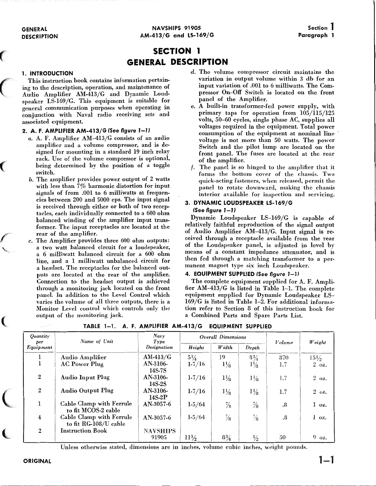
Introduction
Audio
Amplifier
Dynamic
Equipment
Equipment
Shipping
Vacuum
Reference
Electrical
Electrical
General
Theory
The
The
Volume
Triode
Block
Description
of
Cathode
Differential
Compression
Clipper
Diagram
Dynamic
TABLE
Section
1 -
GENERAL
OF
CONTENTS
DESCRIPTION
--------------------------------------------------------------------------------------------------------------------------------------------------AM-413/G
Loudspeaker
Supplied
Required
Data
------------------------------------------------------------------------------------------------------------------------------------------------
Tube
Complement.
Data
------------------------------------------------···------------------------------------------------------------------------------------------
Characteristics
Characteristics
of
Negative
Feedback.
Follower
Amplifier
......
-------------------------------------------------------------------------------------------------------------------
LS~169/G--------------------------------------------------------------------------------------------------------------
-----------------------------------------------------------------
But
Not
Supplied
__________________
of
Audio
of
Dynamic
Section
Urcmts
2-
___________
............
....................
........
---------------------------
_______________________________________________________________________
-----------·-·-·-.
Amplifier
Loudspeaker
THEORY
------------·----------
_____
AM~4l3jG_____________________________________________________________________
LS~169
O:F
-------------
------------------------------------------------------------------------------------------------------
---------------------------------····---------·······------------···--------·-···---------------····--------..
-------------------------------------------------------------------------------------
_________________
.
______
__
____________
_________
--------------------
____ _ ____ ____ _ _____
_____
.___________________________________________________________________________
jG_____________________________________________________________
OPERATION
____
-------
-------------------·-
_______ . _____
________ _ _______
_ _
_____
----------············----------------------------------------------------······--------···-------------------------------------------------···
Loudspeaker
LS~I69fG·----·-···---------·-····-··-------·-·······------······------------------------·-----------------------------
Page
1~1
1~1
1~1
1 ~ 1
1~2
1~2
1
~2
1~2
1~3
1--3
2~
I
2~I
2~I
2~I
2~3
2~3
2~3
2~6
(_
I.
2.
I.
2.
I.
I.
2.
I.
2.
Installation
Adjustment
Audio
Amplifier
Dynamic
Emergency
General
Operation
General
Trouble
Trouble
Shooting
AM~413jG
Loudspeaker
Maintenance
Test
Shooting
Audio
Section
Section
..............
LS~I69jG
Section
Section
Section
-------------------------------------------------·-······-----------------------------------------------
................................
5-
OPERATOR'S
6-
PREVENTIVE
7-
CORRECTIVE
Procedures
Amplifier
AM~4I3/G......................................................................................
Section 8 -PARTS
3-
INSTALLATION
4-
OPERATION
-----·-······----·······------------------·····-------------------------------
MAINTENANCE
MAINTENANCE
MAINTENANCE
........................ ·------------·················---------····--····-···---········-------·····
LISTS
INDEX
3~I
3~I
4~I
4~I
5~0
6~I
6~I
7~2
7~2
ORIGINAL
Page 6
Illustrations
NAVSHIPS 91905
AM-413/G
and LS-169/G
FRONT
MATTER
Figure
l~l
2~1
2~2
2~3
2~4
2~5
2~6
2~7
2~8
2~9
2~10
2~ll
2~12
3~1
3~2
Audio
Simplified
Amplifier
Block
Amplification
Use
of
Negative
Cathode
Cathode
Cathode
Basic
Basic
A
Block
Schematic
Cable
Cable
Follower
Follower
Follower
Principles
Compressor
Triode
Diagram
Connections
Connections
Clipper
of
AM~413/G
Diagram
Without
Feedback
and
of
Compressor
of
Audio
Dynamic
for
Audio
for
Dynamic
LIST
OF
ILLUSTRATIONS
Title
Section I -GENERAL
and
Dynamic
Section
Negative
of
2-
Audio
Feedback
THEORY
Amplifier
.............................................................................................. .
DESCRIPTION
Loudspeaker
OF
OPERATION
AM-413/G
LS~l69/G...................................................
.................................................................. .
............................................................................................................................ .
Differential
Amplifier
Loudspeaker
Amplifier
Circuit..
AM~413/G
LS~l69jG
Section
3-
Amplifier
Loudspeaker
........................................................................................ .
.................................................................................................. .
...................................................................................... .
...................................................................................... .
INSTALLATION
AM~413jG...............................................................................
LS~l69/G.......................................................................
Page
1~0
2~0
2~0
2~0
2~2
2~2
2~2
2~2
2-4
2~4
2-4
2~5
2~6
3~0
3~0
4~1
4~2
5~1
7~1
7~2
7~3
7~4
7~5
7~6
Operating
Operating
Location
Failure
Audio
Report,
Amplifier
Terminal
Terminal
Voltage
Schematic
Controls
Controls
of
Tubes,
Board
Board
and
Resistance
of
of
of
Section
Fuses,
Section
Sample
AM~413/G
(TBIOI),
(TBI02),
Audio
Amplifier
Audio
Amplifier
Dynamic
and
Section
Loudspeaker
5-
Electrolytic
7-
4-
OPERATION
AM-413/G...............................................................................
LS~l69/G.......................................................................
OPERATOR'S
MAINTENANCE
Capacitors...........................................................................
CORRECTIVE
MAINTENANCE
Form.....................................................................................................................
Chassis
Component
Component
Chart
with
Panel
open
.........................................................................
Placement
Placement
Diagram...............................................................
Diagram...............................................................
...................................................................................................................
AM-413/G...............................................................................................
4~0
4~0
5~0
7~1
7-4
7~5
7~5
7~5
7~ll
~
II
ORIGINAL
Page 7
FRONT MATTER
NAVSHIPS
AM-413/G
91905
and LS-169/G
Tables
(
(
('
Table
1-1
1-2
1-3
1-4
5-l
6-1
6-2
7-1
7-2
7-3
7-4
Equipment
Equipment
Shipping
Vacuum
Emergency
Maintenance
Operation
Trouble
Voltage
Tube
Winding
Data
Tube
Shooting
and
Ratings
Data
LIST
Section
Supplied
Supplied
Maintenance
Test
Check
Resistance
for
Amplifier
for
Loudspeaker
-----------------------------------------------------------------------------------------------------------------------------------------------
Complement
Section
Section
Schedule
Procedure
Section 7
1-
...........
---------------------------------------------------------------------------------------------------------------
5-
6--
..............
...........
--CORRECTIVE
OF
TABLES
Title
GENERAL
AM-413/G
LS-169
OPERATOR'S
PREVENTIVE
-----------------------------------------------------------------------------------------------------------
--------------------------------------------------------------------------------------------------------------
DESCRIPTION
.........
------------------------------------------------------------------------------
jG
......
-----------------------------------------------------------------------------
MAINTENANCE
MAINTENANCE
MAINTENANCE
Page
1-1
1-2
1-2
1-2
S-0
6-1
6-2
7-3
7-6
7-8
7-9
8-1
8-2
8-3
8-4
8-5
(
(~
List
of
Major
Table
Cross
Applicable
List
of
Reference
of
Manufacturers-------------------------------------------------------------------------------------------------------··----·--··--------···------
Units
Replaceable
Parts
Color
Codes
Section
.........
------------------------------------------------------------------------------------------------------------------------------
Parts
......
------------------------------------------------------------------------------------------------------------------
LisL·-----------------------------------------------------------------------------------------------------------------------
and
Miscellaneous
8-
PARTS
Data_________________________________________________________________________
LISTS
_ _
8-1
8-2
8-12
8-13
8-14
(c
ORIGINAL
Ill
Page 8
Guarantee and
Installation
Record
The
equipment,
batteries,
for a period
acceptance
found
repaired
United
to
Contractor
the
notified
result
above,
it
is
design
eaid
prising
design,
subject
redesigned
to
or
States
the
Government;
defect
thereof
of
normal
To
the
is
of
also
with
item,
such
such
to
rubber
one
and
of
one
by
the
be
defective
replaced,
designated
to
make
appears
in
writing
expected
extent
guaranteed,
but
item.
the
the
Contractor's
the
understanding
not
less
item
furnished
item
will
hundred
AM-413/G
including
material
year
from
Government
as
to
material,
f.o.b.
any
by
the
provided
repair
within
or
the
within a reasonable
shelf
equipment,
design
subject
than
two
under
be
conclusively
percent
NAVSHIPS 91905
and LS-169/G
GUARANTEE
all
parts
and
spare
normally
the
with
Govemment,
that
replacement
aforementioned
life
including
to
the
that
of
(100%)
consumed
date
of
the
workmanship
point
within
such
deterioration.
or
is
of a design
foregoing
if
ten
percent ( 10%)
any
such
the
contract,
presumed
correction
delivery
understanding
without
guarantee
of
any
all
parts
item,
parts,
in
operation,
of
or
the
continental
delay
will
such
period
time
conditions,
are
to
and
and
and
selected
of
the
found
be
of
or
replacement
except
the
manufacture
defective
the
spare
or
vacuum
equipment
that
all
and
at
not
the
defect
parts,
by
the
against
more
total
quantity
to
he
defective
defective
tubes,
is
guaranteed
to
and
such
items
will
limits
Contractor
of
the
no
expense
obligate
items
is
as
Contractor,
defects
of
design
by a suitably
unless
not
defined
any
as
the
the
such
com-
and
FRONT MATTER
,
be
is
···")
in
to
All
In
view
the
use
conditions
ment
without
of
the
Service,
order
the
repair
authority,
acceptable
of
ment
or
Contract
Serial
Date
Date
Date
Date
to
return
or
this
contractual
The
fails
replaced
number
of
of
of
placed
Blank
such
defective
of
the
fact
of
equipment
as
to
preclude
jeopardizing
therefore,
prevent
of
the
replacement
including
as a
basis
above
one
to
perform
by
the
Number:
of
acceptance
delivery
completion
in
spaces
items
will
he
that
normal
in
the
extended
defective
will
details
for
affecting
guarantee.
year
period
satisfactorily
Contractor
such
remote
retum
the
integrity
may
necessitate
interruption
items
not
of
the
will
will
subject
activities
of
for
be
conditions
expeditious
not
due
be
to
ultimate
of
the
portions
the
defective
of
Naval
expeditious
of
examination
mandatory.
include
to
any
guaranteed
communications.
surrounding
adjustment
defects,
INSTALLATION RECORD
NObsr-52352
equipment
by
the
to
contract
of
installation
on
this
page
...............
destination
-----------------------------------------------------------------------------
..
------------------------------------------------------------------------------
shall
be
Date
........
----------------------------------------------------------------
filled
in
return
Naval
of
the
items
communications,
repair
by
the
The
report
any
portion
anew
of
Contract:
at
the
time
Service
world
for
Contractor
the
under
and
any
under
of
to
repair
of
the
Contractor.
may
result
or
under
or
the
exigencies
of
such
In
such
of a responsible
failure,
the
provisions
time
the
items
this
provision.
22
March
installation.
such
replace-
items
cases
prior
will
be
equip-
repaired
1951
in
in
to
)
••
J
v.J
IV
ORIGINAL
Page 9
FRONT
MATTER
NAVSHIPS 91905
AM-413/G
and LS-169/G
Miscellaneous Data
Safety Notice
Resuscitation
and
(
(
Report
shall
he
made
using
form
of
the
failure
in
reporting
seding
following
l.
2.
specified:
l.
2.
3.
4.
5.
of
safety
instructions.
All
requests
Federal
supply
Name
If
the
Equipment
Name
Manufacturer's
Contractor's
JAN
or
The
attention
Bureau
precautions
of
failure
to
NAVSHIPS
and
failures
or
data:
stock
number
depot,
and
of
of
the
short
appropriate
model
part
drawing
Navy
Ships
REPORT
of
any
the
Bureau
NBS 383
give
the
date
see
Chapter
ORDERING PARTS
requisitions
or,
Signal
description
stock
or
type
and
complete
designation.
and
type
number.
SAFETY NOTICE
of
officers
Manual
to
be
observed.
part
of
this
of
Ships
(revised).
of
installation
67
for
when
ordering
Corps
stock
of
part.
number
designation,
description.
part
number.
and
operating
or
superseding
OF FAILURE
equipment,
in
accordance
of
the
Bureau
replacement
from a Marine
number.
is
not
circuit
personnel
instructions
The
report
of
the
material
available
symbol,
during
equipment.
of
with
shall
Ships
Corps
the
and
is
directed
on
its
entire
current
cover
Manual
should
or
following
item
the
subject
service
regulations
all
For
procedure
or
include
Signal
number.
to
Chapter
of
details
super-
Corps
shall
radio-
life,
the
he
67
(
(,,,
(,
This
equipment
if
contacted
working
equipment,
KEEP
Operating
change
Under
controls
casualties
touching
DON'T
Under
for
presence
AN
TION
DISPLAYED
POSTERS
MEDICINE
with
While
AWAY
tubes
certain
in
always
them.
SERVICE
no
circumstances
the
purpose
or
APPROVED
BY
by
operating
the
equipment.
every
practicable
the
following rules
FROM
personnel
or
make
conditions
the
off
remove
of
assistance
POSTER
THE
PRONE
IN
MAY
BE
AND
SURGERY.
employs
personnel.
LIVE
must
adjustments
dangerous
position
OR
ADJUST
should
servicing
of
another
PRESSURE
EACH
OBTAINED
WARNING
voltages
safety
CIRCUITS:
at
all
due
power
any
or
adjusting
which
Extreme
precaution
must
he
times
inside
potentials
to
charges
and
discharge
ALONE:
person
person
are
caution
has
strictly
observe
equipment
the
all
may
retained
reach
equipment
capable
RESUSCITATION
ILLUSTRATING
METHOD
RADIO,
RADAR,
UPON
THE
REQUEST
dangerous
should
been
observed:
safety
with
exist
by
and
ground
within
of
rendering
RULES
SHALL
OR
SONAR
TO
and
he
exercised
incorporated
regulations.
high
voltage
in
circuits
capacitors.
circuits
or
enter
without
BE
the
aid.
FOR
PROMINENTLY
ENCLOSURE.
THE
BUREAU
may
he
fatal
when
in
this
Do
not
supply
with
the
immediate
RESUSCITA-
on.
power
To
avoid
prior
enclosure
OF
to
ORIGINAL
v
Page 10
-
I
0
0
MONITOR
LEVEL
0
-
C1)
"'
t'l
-
o·
:I
0
0
COMPRESSOR
ON
OFF
0
0
0
0
LEVEL
4 5 6
307
2 e
I 9
0
10
AM
413/G
AMPLIFIER,
SUPPLY
11SV
SERIAL-
MANUF'
...
NAVY
.
CTUREO
DEPARTMENT
BUREAU
HA~MAN
KARDON
:;~.;~;:.
~~-
®
'~'
A F
11i!l60"-'
FOR
0
Q
DF
SHIPS
lNC
@
0
POWER
ON
®
Off
®
)>
3:
I
o~:=ooz
-)>
~<
Gl"'
::r:
Q
:;;
:I
"'
a.
-o
r-
....
~~'-o
.!.~
o-
-o
Gl
-
0
!:li:J
Gl
z
)>
r-
LEVEL
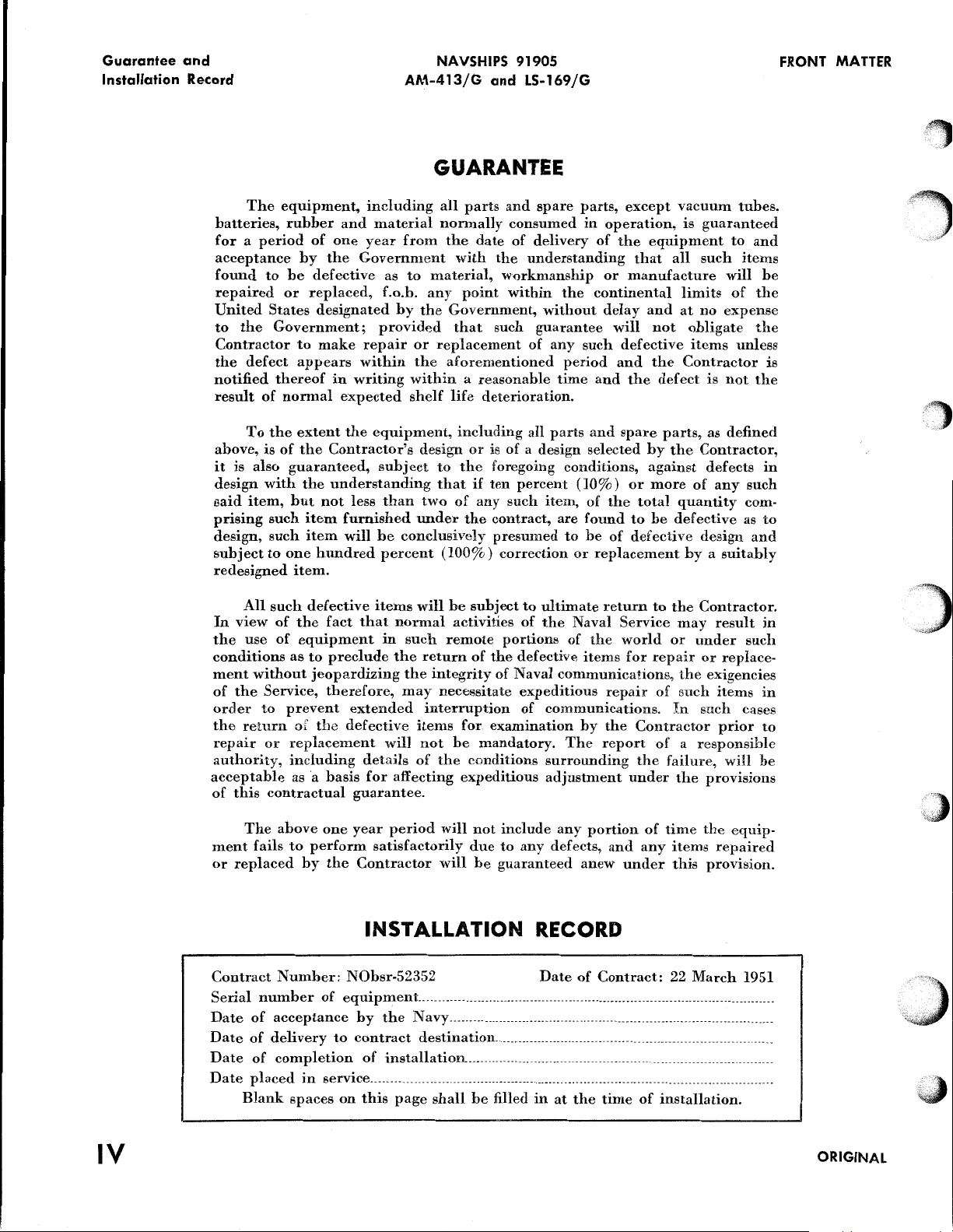
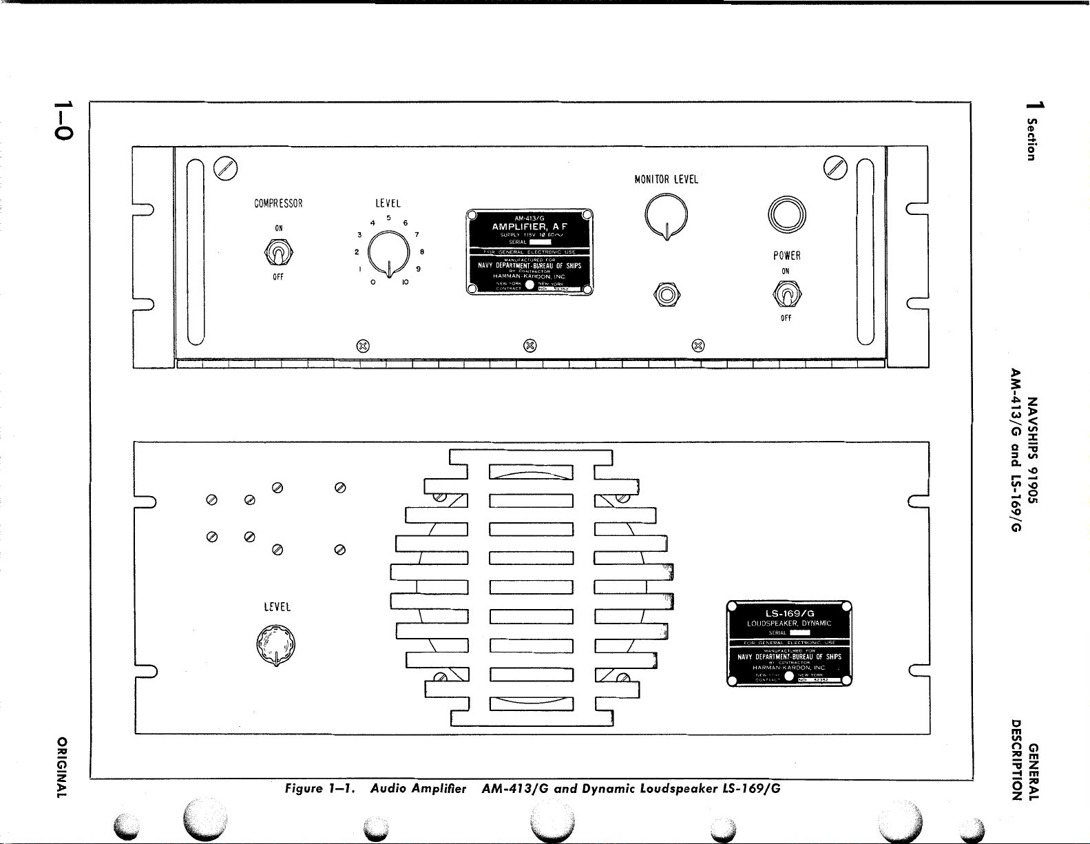
Figure
1-l.
Audio
Amplifier
AM-413/G
and
Dynamic
Loudspeaker
LS-169/G
•
LOUDSPEAKER, DYNAMIC
SERIAL-
"""'UFACTURED
NAVY
DEPARTMENT
-BUREAU
Ho.~-:MAN-K.AR~~:·v;,~:
CGN,~AC'
~
•
FOfl
OF
SHIPS
•
•
LS-169/G
0
m
na
"'
!:li:Jm
:;;z
-tm
-!:li:J
0)>
Zr-
Page 11
(
(c
l
GENERAL
DESCRIPTION
1. INTRODUCTION
This
instruction
ing
to
the
description,
Audio
speaker
general
conjunction
associated
2.
Amplifier
LS-I69
communication
A.
F.
AMPLIFIER
a. A.
F.
amplifier
signed
rack.
being
jG.
with
equipment.
Amplifier
and a volume
for
mounting
Use
of
determined
switch.
b.
The
amplifier
with
less
than
signals
cies
is
tacles,
balanced
former.
rear
c.
The
a
a 6
line,
a
puts
of
between
received
each
The
of
the
Amplifier
two
watt
milliwatt
and
headset.
are
from
through
winding
a I
The
located
Connection
through a monitoring
panel.
varies
Monitor
output
Quantity
per
Equipment
In
addition
the
volume
Level
of
the
I
I
1
I
I
Audio
l
I
AC
I
2
I
Audio
2
I
Audio
I
I
Cable
to
1
i
Cable
I
to
2
Instruction
I
Unless
hook
contains
operation,
AM-413/G
This
equipment
purposes
Naval
AM-413/G
AM-4I3/G
in a standard
the
volume
by
provides
7%
harmonic
.OOI
to 6 milliwatts
200
and
5000 cps.
either
individually
of
the
input
receptacles
amplifier.
provides
balanced
balanced
milliwatt
receptacles
at
the
to
the
headset
to
of
all
control
monitoring
TABLE
Name
of
Amplifier
Power
Input
Plug
Plug
Output
Clamp
fit MCOS-2
Clamp
fit
RG-I08/U
Book
otherwise
information
and
and
Dynamic
when
radio
receiving
lSee figure J-JJ
consists
compressor,
compressor
the
position
power
output
distortion
The
or
both
connected
amplifier
are
three
600
circuit
for a loudspeaker,
circuit
unbalanced
for
the
rear
of
output
jack
located
the
Level
three
outputs,
which
controls
jack.
1-1.
A.
Unit
Plug
with
Ferrule
cable
with
Ferrule
cable
stated,
NAVSHIPS 91905
AM-413/G
and
LS-169/G
SECTION 1
GENERAL DESCRIPTION
d.
The
volmne
pertain-
maintenance
Loud-
is
suitable
operating
sets
of
an
audio
and
is
I9
inch
relay
is
optional,
of a toggle
of 2 watts
for
input
at
frequen-
input
signal
of
two
recep-
to
a 600
input
trans-
located
ohm
for
at
outputs:
a 600
circuit
balanced
the
amplifier.
is
achieved
on
the
front
Control
which
there
only
F.
AMPLIFIER
Navy
Type
I
I Designation
1
AM-4I3/G
I AN-3I06-
I
l4S-7S
AN-3I06-
I4S-2S
AN-3106-
I4S-2P
AN-3057-6
AN.3057-6
I NAVSHIPS
9I905
dimensions
of
for
in
and
de-
ohm
the
ohm
for
out-
is a
the
are
AM-413/G
I
I
in
variation
input
variation
pressor
panel
e. A
built-in
primary
volts,
50-60
voltages
consumption
voltage
Switch
front
of
the
f.
The
panel
forms
quick-acting
panel
interior
3.
DYNAMIC
(See
figure
Dynamic
relatively
of
Audio
ceived
of
the
means
then
manent
4. EQUIPMENT
The
fier
faithful
Amplifier
through a receptacle
Loudspeaker
of a constant
fed
through a matching
magnet
complete
AM-413/G
equipment
I69/G
tion
a
is
refer
Combined
EQUIPMENT
Overall
Height
listed
to
51Jt
l-7/16
I-7/16
I-7/I6
I-S/64
I-5/64
llVz
inches,
I
I
I
I
volume
On-Off
of
required
is
and
panel.
amplifier.
the
to
available
LOUDSPEAKER
7-JJ
Loudspeaker
supplied
Section 8 of
Parts
Dimensions
Width
I9
lYs
IYs
1Ys
3%
compressor
in
output
of
volume
.001
Switch
the
Amplifier.
transformer-fed
taps
for
operation
cycles,
not
the
is
bottom
of
more
The
so
single
in
the
the
equipment
pilot
fuses
hinged
cover
fasteners,
rotate
downward,
for
reproduction
AM-413/G.
panel,
impedance
type
six
inch
SUPPLIED
lSee figure
equipment
is
listed
in
for
Dynamic
in
Table
1-2.
and
Spare
SUPPLIED
Depth
I
8%
IYa
I
lYa
IYs
%
Ys
%
7/,
.ll
Vz
cubic
inches,
circuit
within 3 db
to 6 milliwatts.
is
located
power
from
phase
AC,
equipment.
at
than
50 watts.
lamp
are
located
are
located
to
the
amplifier
of
the
when
released,
making
inspection
LS-169/G
LS-169/G
of
the
Input
available
is
adjusted
attenuator,
transformer
Loudspeaker.
J-JJ
supplied
Table
for
I-I.
Loudspeaker
For
additional
this
instruction
Parts
List.
I
I
Volume
I
I 870
I
1.7 2 oz.
I
I
1.7
I
1.7 2 oz.
. 3
. 8
I
I
I
so
!
weight
pounds.
Section
Paragraph
maintains
The
on
the
supply,
105/llS/125
supplies
Total
nominal
The
at
the
chassis.
permit
the
and
servicing.
is
capable
signal
signal
from
the
in
level
to a per-
A.
F.
The
complete
informa-
book
I
I
I
Weight
!
lSVz
I
I
I
I
2 oz.
I
I
I oz .
1 oz . 4
I
i
I
9 oz.
!
the
for
an
Com-
front
with
all
power
line
power
on
the
rear
that
Two
the
chassis
of
output
is
re-
rear
by
and
Ampli-
LS-
for
1
it
is
I
ORiGINAL
1-1
Page 12
1 Section
Paragraph
NAVSHIPS 91905
5
AM-413/G
and
LS-169/G
GENERAL
DESCRIPTION
Quantity
per
Equip-
ment
1
1
1
Dynamic
Plug
Cable
to
2
Instruction
Unless
5. EQUIPMENT
None
of
equipment
devices
as
6. SHIPPING DATA
sizes
used
radio
A
list
is
given
Shipping
Box
No.
of
REQUIRED
the
is
supplied,
in
conjunction
receiving
shipping
in
Table
cables
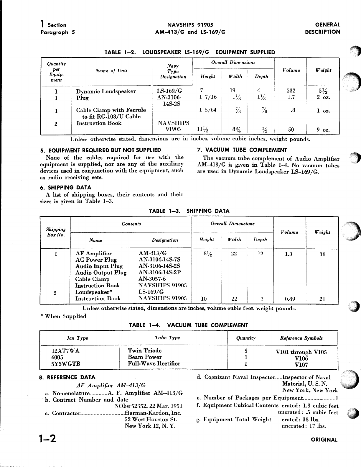
TABLE
Name
Loudspeaker
Clamp
fit
RG-108/U
Book
otherwise
required
nor
sets.
boxes,
1-3.
Name
of
with
BUT
are
with
their
1-2.
Unit
Ferrule
Cable
stated,
NOT
any
the
Contents
LOUDSPEAKER LS-169/G EQUIPMENT
Navy
Type
Designation
LS-169/G
AN-3106-
Overall
Height
7 19 4
l
7/16
14S-2S
l
5/64
NAVSHIPS
dimensions
SUPPLIED
for
use
of
the
equipment,
contents
TABLE
91905
are
with
auxiliary
such
and
their
1-3.
Designation
the
11¥2
in
inches,
volume
7. VACUUM
The
vacuum
AM-413/G
are
used
SHIPPING DATA
Overall
Height
in
SUPPLIED
Dimensions
Width
lYs lYs
Ys
8%
cubic
inches,
TUBE
COMPLEMENT
tube
complement
is
given
in
Dynamic
Dimensions
Width
Depth
Ys
Yz
weight
Table
Loudspeaker
Depth
1-4.
Volume
532
1.7 2 oz.
.8
so
pounds.
of
Audio
No
vacuum
LS-169/G.
Volume
Weight
S¥2
l oz.
9 oz.
Amplifier
tubes
Weight
1
2
*
When
l2AT7WA
6005
5Y3WGTB
8.
REFERENCE
a.
Nomenclature
b.
Contract
c.
Contractor
AF
AC
Audio
Audio
Cable
Instruction
Loudspeaker*
Instruction
Supplied
]an
Type
--
DATA
AF
Number
.... --------------------------Harman-Kardon,
Amplifier
Power
Input
Output
Clamp
Unless
Amplifier
............ A.
Plug
Plug
Plug
Book
Book
otherwise
AM-413/G
F.
and
date
NObsr52352,
AM-413/G
AN-3106-14S-7S
AN-3106-14S-2S
AN-3106-14S-2P
AN-3057-6
NA
VSHIPS
LS-169/G
NA
VSHIPS
stated,
TABLE
Twin
Beam
dimensions
1-4.
Triode
Power
Full-Wave
Amplifier
22
52
West
Houston
New
York
91905
91905
VACUUM
Tube
Type
Rectifier
AM-413/G
Mar.
1951
Inc.
St.
12,
N.Y.
are
8¥2
10 22
inches,
volume
TUBE
d.
Cognizant
e.
Number
f.
Equipment
g.
Equipment
22
cubic
feet,
COMPLEMENT
Quantity
5
l
l
Naval
of
Packages
Cubical
Total W eight
12
7
I
weight
Inspector
per
Contents
1.3
0.89
38
21
i
-
pounds.
Reference
VIOl
Symbols
through
Vl05
V106
Vl07
.....
Inspe~tor
Material,
New
York,
Equipment._
crated:
uncrated:
_______
crated:
uncrated:
--·-
of
Naval
U.
S.
N.
New
York
____________________
1.3
cubic
.5
cubic
38
lbs.
!
feet
feet
17 lbs.
;:>
,
,~,
,J
1-2
ORIGINAL
Page 13
GENERAL
DESCRIPTION
NAVSHIPS
AM-413/G
and
91905
LS-169/G
Section 1
Paragraph
8
(
(~
(
a.
Nomenclature
h.
Contract
Contractor
c.
d.
Cognizant
e.
Number
Equipment
f.
g.
Equipment
9.
ELECTRICAL
AMPLIFIER
(a)
Frequency
(b)
Input
(c)
Input
Dynamic
LeveL
Loudspeaker
..
Dynamic
Number
.........
---------------------
Naval
of
Packages
Cubical
Total
CHARACTERISTICS
AM-413/G
Response
Impedance
...........................
LS-169/G
Loudspeaker
and
date
NOhsr52352, 22 Mar. 1951
Harman-Kardon,
52
West
Houston
York
New
Inspectorinspector
Material,
NewYork,N.
per
Equipment__
Contents
crated:
uncrated:
WeighL
±
ldb
...................... 600
.89 cubic
............
crated:
uncrated:
OF
AUDIO
from
200
OOl
to 6 milliwatts
ohms ± 10%
LS-169/G
Inc.
St.
12,
N.Y.
of
Naval
U. S. N.
Y.
________________
.3 cubic
to
5000
}
feet
feet
21 lhs.
6 lbs.
cps
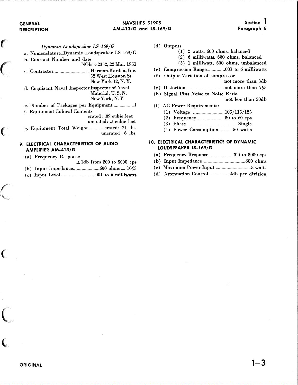
(d)
Outputs
(e)
Compression
(f)
Output
(g)
Distortion
(h)
Signal
(
i)
AC
(I)
(2)
(
3)
(
4)
10.
ELECTRICAL
LOUDSPEAKER
(a)
Frequency
(b)
Input
(c)
Maximum
(d)
Attenuation
(
1)
2 watts, 600
(2) 6 milliwatts,
(
3) l milliwatt,
Range
Variation
................................
Plus
Noise
Power
Requirements:
Voltage
Frequency
Phase
Power
Impedance
__________________________
______________________
----------------------------------------Single
Consumption
CHARACTERISTICS OF
LS-169/G
Response
Power
Input..
Control
ohms,
...............
of
compressor
to
Noise
.................... 200
----------------------------------600
----------------4db
balanced
600
ohms,
600
ohms,
OOI
not
not
Ratio
not
l05/ll5/125
50
............
............................ S
balanced
unbalanced
to 6 milliwatts
more
than
more
than
less
than
to
60
cps
SO
watts
DYNAMIC
to
5000
per
division
ohms
watts
3db
7%
50db
cps
(
(k_
(,
ORIGINAL
1-3
Page 14
2 Section
NAVSHIPS 91905
AM-413/G
and LS-169/G
THEORY
OPERATION
OF
~
~
INPUT
INPUT
Figure
rv
2-1.
VOLUME
COMPRESSOR
Simplified
r--
Block
OFF
ON
Diagram
AMPLIFIER
COMPRESSOR
SWITCH
of
Audio
Amplifier
I--
AMPliFIER
STAGES
AM-413/G
rv
OUTPUT
OUTPUT
l
')
~-
ifi"
')
~~I
.......
l
-::.:.!="
Figure
SUBTRACTION
CIRCUIT
2-2.
Figure
Amplification
~
~
FEEDBACK
2-3.
Use
Without
VOLTAGE
of
Negative
Negative
AMPLIFIER
Feedback
Feedback
f-.
,~)
f\J"'~'
l
..
\~
\~
2-0
ORIGINAL
Page 15
THEORY OF
OPERATION
NAVSHIPS
AM-413/G
and
91905
LS-169/G
Section 2
Paragraph
1
(
(
("
"·~t
'
(
(
(
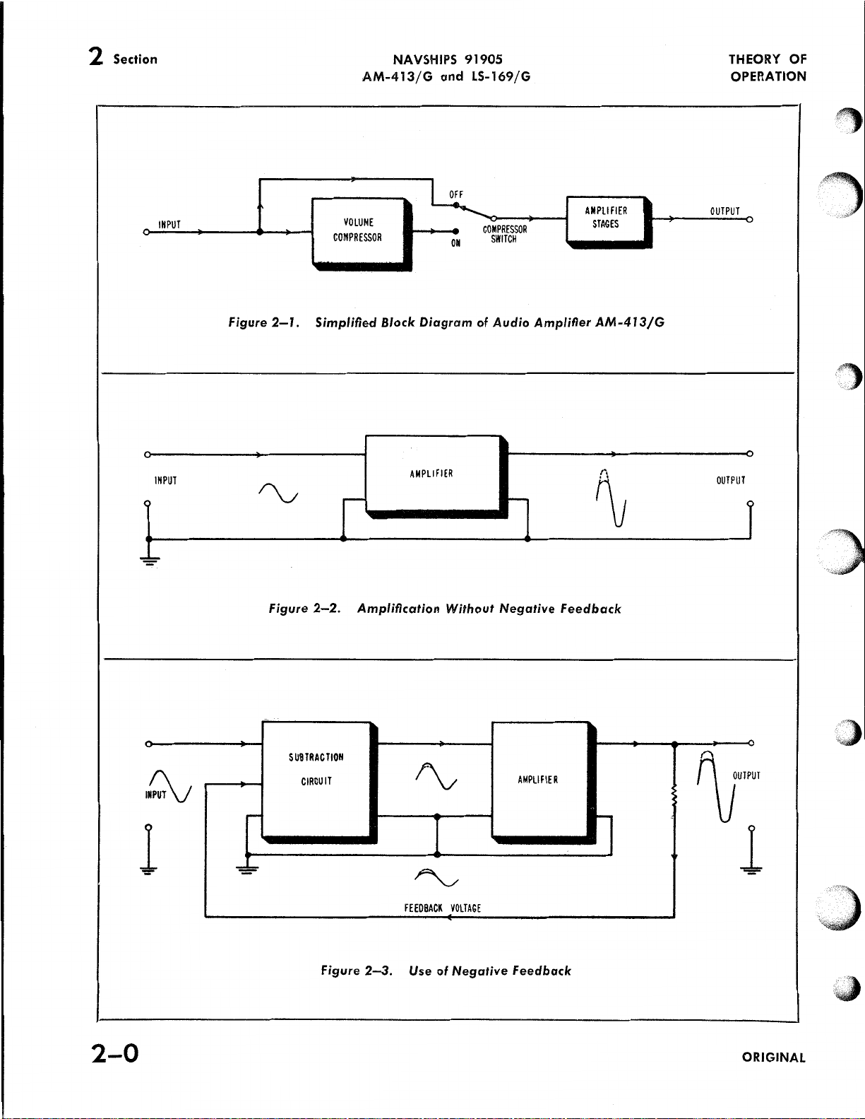
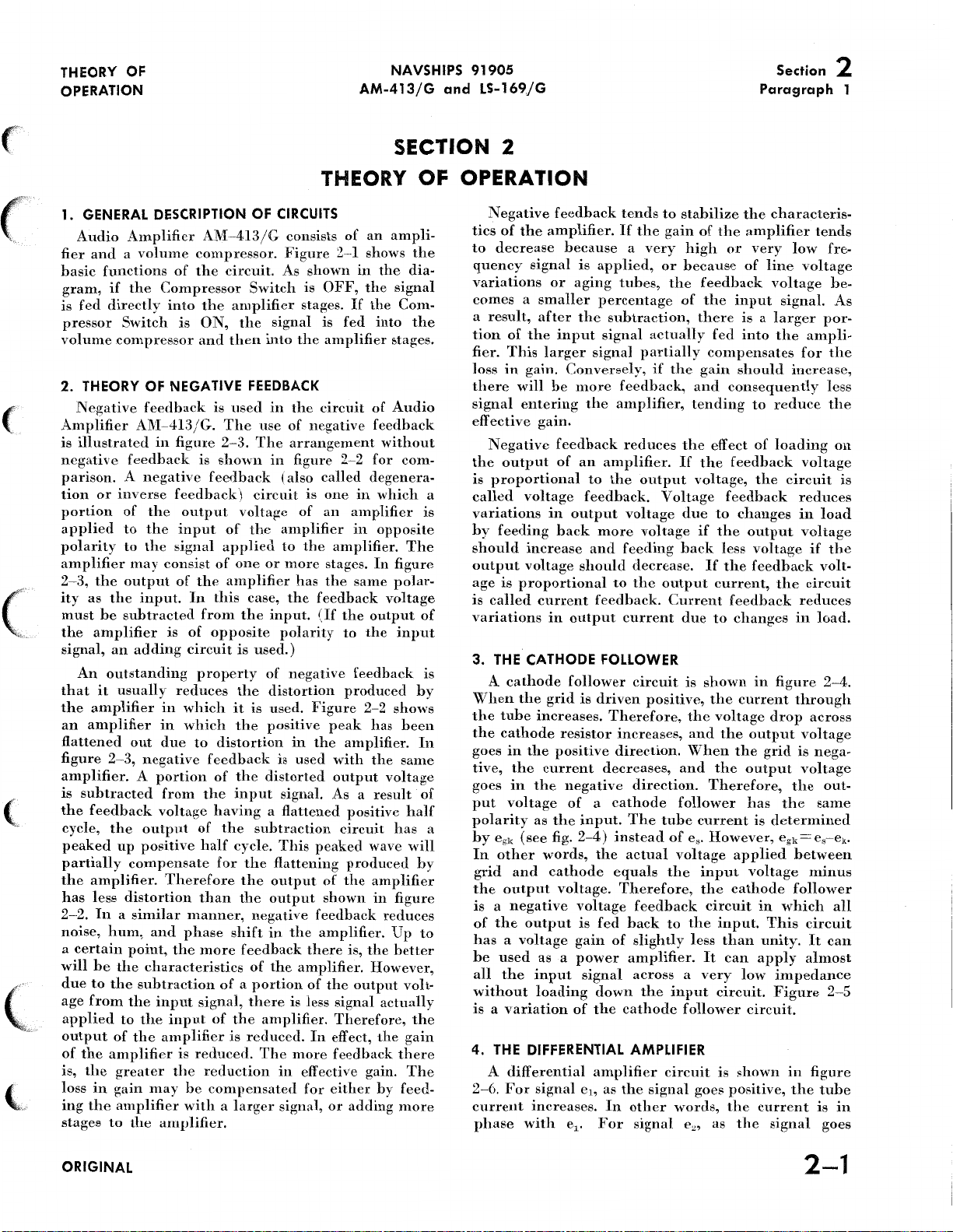
THEORY OF OPERATION
1. GENERAL DESCRIPTION OF CIRCUITS
Audio
fier
basic
gram,
is
fed
pressor
volume
2.
Negative
Amplifier
is
illustrated
negative
parison. A negative
tion
portion
applied
polarity
amplifier
2-3,
ity
must
the
sig~'lal,
An
that
the
an
flattened
figure
amplifier. A portion
is
the
cycle,
peaked
partially
the
has
2-2.
noise,
a
certain
will
due
age
applied
output
of
is,
loss
ing
stages
Amplifier
and a volume
functions
if
the
directly
Switch
compressor
THEORY OF NEGATIVE FEEDBACK
feedback
AM-413/G.
in
feedback
or
inverse
of
the
to
the
to
the
may
the
output
as
the
input.
be
subtracted
amplifier
an
adding
outstanding
it
usually
amplifier
amplifier
out
2-3,
negative
subtracted
feedback
the
output
up
positive
compensate
amplifier.
less
distortion
In a similar
hum,
and
point,
be
the
characteristics
to
the
subtraction
from
the
input
to
the
of
the
the
amplifier
the
greater
in
gain
may
the
amplifier
to
Lhe
AM-413/G
compressor.
of
the
circuit.
Compressor
into
the
is
ON,
and
is
The
figure
2-3.
is
shown
feedback
feedback)
output
input
signal
consist
of
is
reduces
in
in
due
from
voltage
Therefore
the
input
amplifier
is
the
amplifier.
of
applied
of
the
In
this
from
of
opposite
circuit
property
which
which
to
distortion
feedback
of
the
having a flattened
of
the
half
for
than
manner,
phase
more
of a portion
signal,
of
reduced.
reduction
be
compensated
with a larger
Switch
amplifier
the
signal
then
into
used
in
use
The
in
circuit
voltage
the
one
or
amplifier
case,
the
input.
is
used.)
of
the
distortion
it
is
used.
the
positive
the
distorted
input
subtraction
cycle.
the
flattening
the
output
the
output
negative
shift
in
feedback
of
the
there
the
amplifier.
is
reduced.
The
consists
Figure
As
is
stages.
the
the
of
arrangement
figure
(also
of
amplifier
to
the
more
has
the
polarity
negative
in
is
used
signal.
This
the
amplifier.
is less
more
in
effective
for
signal,
shown
OFF,
is
circuit
negative
called
is
an
feedback
(If
Figure
the
peaked
of
shown
feedback
amplifier.
there
of
In
of
an
2-1
shows
in
the
If
the
fed
amplifier
of
feedback
2-2
for
degenera-
one
in
amplifier
in
amplifier.
stages.
the
In
same
the
output
to
the
feedback
produced
2-2
peak
has
amplifier.
with
the
output
As a
result
positive
circuit
wave
produced
the
amplifier
in
is,
the
However,
the
output
signal
Therefore,
effect,
feedback
gain.
either
or
adding
SECTION 2
ampli-
the
the
dia-
signal
Com-
into
the
stages.
Audio
without
com-
which
opposite
the
by
The
figure
polar-
voltage
of
input
by
shows
been
In
same
voltage
of
half
has
will
by
figure
reduces
Up
to
better
volt-
actually
the
gain
there
The
feed-
more
a
is
is
a
Negative
tics
of
to
decrease
quency
variations
comes a smaller
a
result,
tion
fier.
This
loss
in
there
signal
effective
Negative
the
output
is
proportional
called
variations
by
feeding
should
output
age
is
is
called
variations
3.
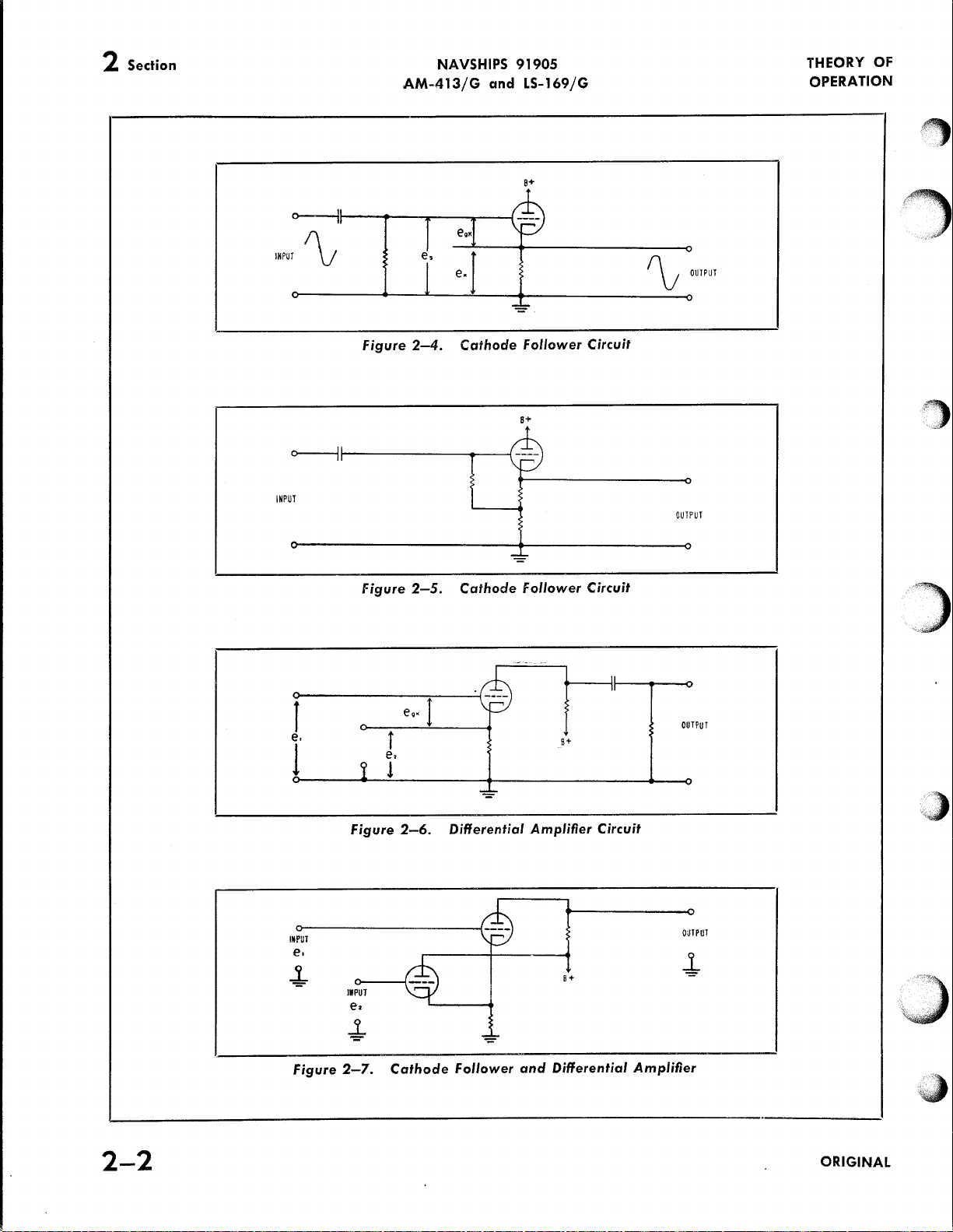
THE CATHODE FOLLOWER
A
cathode
When
the
tube
the
cathode
goes
in
tive,
goes
put
voltage
polarity
by
egk
In
other
grid
the
output
is a negative
of
the
has a voltage
be
used
all
the
without
is a variation
4.
THE
A
2-6.
For
current
phase
feedback
the
amplifier.
because a very
signal
or
aging
after
of
the
input
larger
gain.
Conversely,
will
be
entering
gain.
feedback
of
voltage
in
output
back
increase
voltage
proportional
current
in
output
follower
the
grid
increases.
resistor
the
positive
the
current
in
the
negative
of a cathode
as
the
(see
fig.
words,
and
cathode
voltage.
output
as a
input
loading
of
DIFFERENTIAL AMPLIFIER
differential
signal
increases.
with
e
1
is
applied,
percentage
the
subtraction,
signal
signal
more
the
amplifier,
an
amplifier.
to
the
feedback.
more
and
should
to
feedback.
is
driven
Therefore,
increases,
direction.
decreases,
input.
2-4)
instead
the
equals
voltage
is
fed
gain
of
power
signal
down
the
amplifier
e1, as
In
For
•
tends
If
tubes,
feedback,
reduces
voltage
feeding
current
Therefore,
cathode
the
to
stabilize
the
gain
of
high
or
because
the
feedback
of
the
there
actually
partially
if
output
Voltage
voltage
decrease.
the
circuit
positive,
direction.
The
tube
actual
feedback
back
slightly
amplifier.
across a very
the
signal
other
signal
the
and
tending
the
If
voltage,
due
back
output
Current
due
is
the
and
When
and
follower
current
of
e
8
voltage
the
to
the
less
input
follower
circuit
goes
words,
e
,
2
compensates
gain
the
if
If
shown
the
Therefore,
•
However,
input
the
circuit
It
the
the
amplifier
or
very
of
line
input
is a larger
fed
into
should
consequently
to
effect
of
feedback
the
feedback
to
changes
the
output
less
voltage
the
feedback
current,
feedback
to
changes
in
current
voltage
the
output
the
grid
the
output
has
is
applied
voltage
cathode
in
input.
circuit.
is
as
than
unity.
can
apply
low
circuit.
shown
positive,
the
current
the
This
characteris-
tends
low
fre-
voltage
voltage
signal.
por-
the
ampli-
for
the
increase,
less
reduce
loading
the
figure
drop
determined
egk
impedance
Figure
signal
voltage
circuit
reduces
in
voltage
if
circuit
reduces
in
load.
through
across
voltage
is
nega-
voltage
the
the
same
= es-ek.
between
minus
follower
which
circuit
It
almost
in
figure
the
is
the
load
the
volt-
2-4.
out-
can
2-5
tube
goes
be-
As
on
is
all
in
ORIGINAL
2-1
Page 16
2
Section
NAVSHIPS 91905
AM-413/G
<>---lt-----t---:..------.---(
INPUT~
and LS-169/G
a+
THEORY
OPERATION
~OUTPUT
OF
~
cr----Jf
INPUT
..,-
J
e.
1
Figure
Figure
e,
Figure
j
!
2-4.
2-5.
e
••
2-6.
Cathode
Cathode
J
Differential
-
Follower
S+
\;:::::.,-
~
Follower
~-
--
Amplifier
B+
Circuit
Circuit
Circuit
~
OUTPUT
OUTPUT
y·,_,,.,
·"·c·
.. · ...
)
''"
2-2
INPUT
e.
-!-
figure
II
PUT
e •
..1.
=
2-7.
Cathode
Follower
and
B+
Differential
OUTPUT
-!-
Amplifier
iJ
ORIGINAL
Page 17
THEORY
OPERATION
OF
NAVSHIPS
AM-413/G
and
91905
LS-169/G
Section 2
Paragraph 4
positive,
the
the
other
Thus,
e1 and
(see
fier
two
same
and
he
other
effective
equals
2-7
cathode
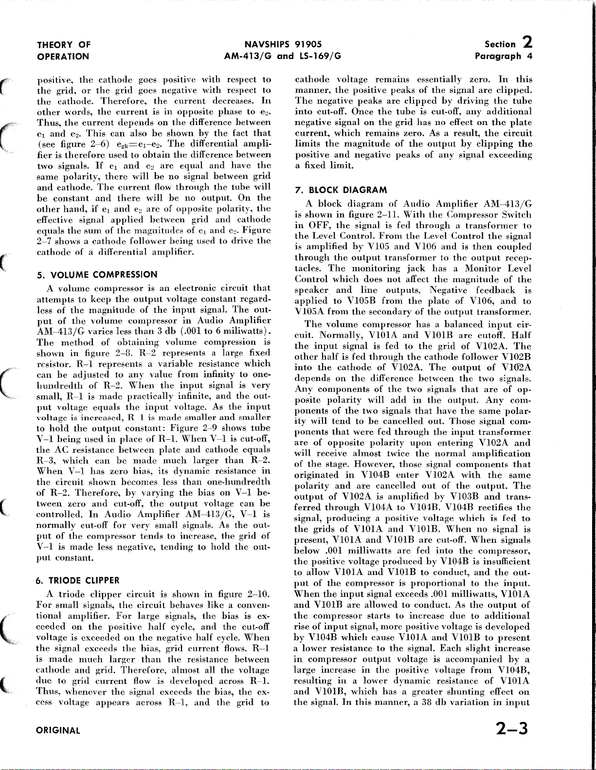
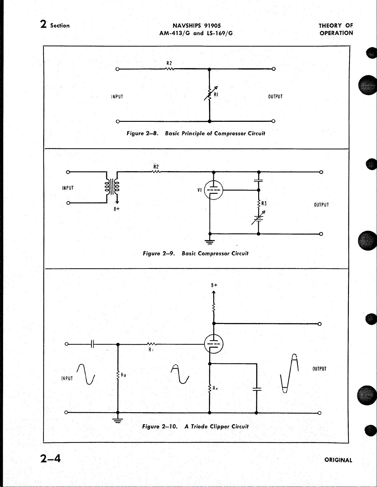
5. VOLUME COMPRESSION
A
attempts
less
put
AM~413/G
The
shown
resistor.
can
hundredth
small,
put
voltage
to
hold
V-1
the
R~3,
When
the
of
tween
controlled.
normally
put
V ~ l
put
6.
TRIODE
A
For
tional
ceeded
voltage
the
is
made
cathode
due
Thus,
cess
the
cathode
grid,
or
the
cathode.
words,
the
e
figure
is
therefore
signals.
polarity,
cathode.
constant
hand,
current
•
This
2
2~6)
Therefore,
the
used
If
there
Tbe
and
if
e1 and
signal
the
sum
of
shows a cathode
of a differential
volume
of
of
to
the
the
compressor
keep
magnitude
volume
varies
method
in
be
R-1
voltage
is
being
AC
which
V ~ l
circuit
R~2.
zero
of
figure
R-1
represents a variable
adjusted
of
R~2.
is
made
equals
increased,
the
output
used
in
resistance
can
has
shown
Therefore,
and
In
Audio
cut-off
of
the
compressor
is
made
less
constant.
CLIPPER
triode
small
clipper
signals,
amplifier.
on
the
is
exceeded
signal
exceeds
much
and
grid.
to
grid
current
whenever
voltage
appears
goes
grid
goes
current
depends
can
also
egk=e1~e2.
to
obtain
e1
and
ez
will
current
there
will
e2 are
applied
the
magnitudes
follower
is
the
output
of
compressor
less
than 3 db
obtaining
2~8.
R-2
to
any
value
When
practically
the
input
R-1
is
constant:
place
of
between
he
made
zero
bias,
becomes
by
varying
cut-off,
Amplifier
for
very
tends
negative,
circuit
the
circuit
For
large
positive
larger
on
the
half
the
bias,
than
Therefore,
flow
the
signal
across
positive
negative
the
is
in
on
he
shown
The
are
he
no
flow
he
of
between
being
current
opposite
the
difference
differential
the
difference
equal
signal
through
no
opposite
grid
of
used
with
with
by
and
output.
e1
and
amplifier.
an
electronic
voltage
the
volume
input
in
(.001
constant
signal.
Audio
to 6 miliwatts).
compression
represents a large
resistance
from
infinity
the
input
signal
infinite,
voltage.
made
smaller
the
Figure
R-1.
plate
much
its
less.
output
When
and
larger
dvnamic
than
the
bias
2-9
V~l
cathode
one-hundredth
voltage
AM-413/G,
small
signals.
to
increase,
tending
is
signals,
negative
grid
the
is
exceeds
to
shown
behaves
the
cycle,
and
half
current
resistance
almost
developed
the
R--1,
and
hold
in
like a conven-
all
respect
respect
decreases.
phase
to
between
the
fact
ampli-
between
have
between
the
tube
On
polarity,
and
cathode
ez.
Figure
to
drive
circuit
regard-
The
Amplifier
which
to
is
and
the
As
the
input
and
smaller
shows
is
cut-off,
equals
than
resistance
on
V~l
can
V~l
As
the
the
grid
the
figure
cycle.
bias
the
2-10.
is
cut-off
When
flows.
between
the
voltage
across R--1.
bias,
the
the
grid
to
to
In
e2.
that
the
grid
will
the
the
the
that
out-
is
fixed
one-
very
out-
tube
R~2.
in
he-
he
is
out-
of
out-
ex-
R~l
ex-
to
cathode
manner,
The
negative
into
cut-off.
negative
current,
limits
the
positive
a
fixed
7.
BLOCK
A
block
is
shown
in
OFF,
the
Level
is
amplified
through
tacles.
Control
speaker
applied
VlOSA
cuit.
the
other
into
The
Normally,
input
half
the
from
volume
depends
Any
components
posite
polarity
ponents
ity
will
ponents
are
of
opposite
will
receive
of
the
stage.
originated
polarity
output
ferred
signal,
the
through
producing a positive
grids
present,
below
the
to
put
When
and
the
rise
by
a
in
large
.001
positive
allow
of
the
the
VlOlB
compressor
of
input
Vl04B
lower
compressor
increase
resulting
and
VlOlB,
the
signal.
voltage
the
positive
peaks
Once
signal
which
magnitude
and
negative
limit.
DIAGRAM
diagram
in
figure
the
signal
Control.
by
the
output
The
monitoring
which
and
line
to
VlOSB
the
signal
is
fed
cathode
on
the
of
the
tend
to
that
were
almost
However,
in
and
are
of
Vl02A
of
VIOlA
VIOlA
milliwatts
voltage
VIOlA
compressor
input
are
signal,
which
resistance
in a lower
which
In
this
remains
peaks
are
the
tube
on
the
grid
remains
of
peaks
of
2~11.
is
fed
From
Vl05
and
transformer
does
not
outputs.
from
secondary
compressor
VIOlA
is
fed
through
of
Vl02A.
difference
of
the
will
add
two
signals
he
cancelled
fed
through
polarity
twice
those
Vl04B
enter
cancelled
is
amplified
Vl04A
to
and
and
VlOlB
are
produced
and
VlOlB
is
signal
exceeds
allowed
starts
to
more
cause
VIOlA
to
the
output
in
the
voltage
positive
dynamic
has a greater
manner, a 38
essentially
of
clipped
is
has
zero.
the
of
Audio
With
the
cut-off,
no
As a result,
output
any
Amplifier
the
zero.
signal
by
are
driving
any
effect
on
by
clipping
signal
Compressor
through a transformer
the
Level
Control
Vl06
and
is
then
to
the
output
jack
has a Monitor
affect
the
magnitude
the
of
Negative
plate
the
output
of
feedback
Vl06,
transformer.
has a balanced
and
VlOlB
to
the
the
cathode
The
between
two
signals
in
the
that
out.
upon
the
signal
Vl02A
out
Vl04B.
voltage
VlOlB.
are
fed
by
to
proportional
to
conduct.
increase
positive
signal.
are
grid
of
follower
output
the
that
output.
have
the
Those
the
input
entering
normal
components
with
of
the
by
Vl03B
Vl04B
which
When
cut-off.
into
the
Vl04B
conduct,
.001
milliwatts,
As
due
voltage
and
VlOlB
Each
is
accompanied
voltage
cutoff.
Vl02A.
two
same
transformer
Vl02A
amplification
output.
rectifies
no
When
compressor,
is
and
to
the
to
is
slight
from
resistance
shunting
db
variation
In
this
clipped.
the
tube
additional
the
plate
the
circuit
the
exceeding
AM~413/G
Switch
to
the
signa]
coupled
recep-
Level
of
the
is
and
to
input
cir-
Half
The
Vl02B
of
VHf2A
signals.
are
of
op-
Any
com-
polar-
signal
com-
and
that
the
same
The
and
trans-
the
is
fed
to
signal
is
signals
insufficient
the
out-
the
input.
VIOlA
output
of
additional
developed
to
present
increase
by
a
Vl04B,
of
VIOlA
effect
on
in
input
ORIGINAL
2-3
Page 18
2 Section
NAVSHIPS
AM-413/G
R2
and
91905
LS-169/G
THEORY OF
OPERATION
INPUT
INPUT
B+
Figure
2-8.
R2
Figure
Basic
2-9.
Principle
Basic
Compressor
Rl
of
Compressor
OUTPUT
Circuit
OUTPUT
Circuit
2-4
B+
ORIGINAL
Page 19

,..,
~.
r'
-~
-~
"'""
0
"'
(5
z
)>
I""
3
,------------------------------------~
I I
I I
I I
LEVEL
CONTROL
VI02B
I
I
I
I
I
I
I
I
I
I
I
I
I
I
I
I
I
L
________________________________________
V
104
B
RECTI-
FIER
CATHODE
FOLLOVIER
V
CATHODE
FOLLOWER
VOLUME
104A
v
1038
VOLTAGE
AMPLIFIER
COMPRESSOR
0-1
-a:r:
mm
::~::~0
)>::a
-1-(
oo
z"''''
~------------
I I
1 r
I I
I I
OFF
I
I
I
I
J
L------------------------------~
AMPLIFIER
--
MONITOR
OUTPUT
---
STAGES
-----~
I
I
I
I
I
I
I
I
I
I
(Til
BALANCED
OUTPUTS
l>
3:
.b.z
....
)>
w<
a:r:
-"'
Q
::;
:::J
"'
0..-o
r-
....
"'-o
'o
Q:u.
~
a
~
I
U1
Figure
2-l
1.
Block
POWER
Diagram
v
107
SUPPLY
of
Audio
Amplifier
AM-4 J 3/G
II)
"'
,..
c;·
-
:::J
~
Page 20

2 Section
Paragraph 7
signal
level
tion
in
output
If
the
compressor
change
will
compress
this
mixed
allowed
plifier
like a thump
the
signal
is
ity,
output.
signal
differential
this
compressor,
smaller
the
the
AC
The
instance
from
produce a large
the
surge
with
to
into a loudspeaker
amplifier
from
fed
into
both
and
is
The
and
transient.
If a very
magnitude.
signal, a DC
rectifier
voltage
charging
it
is
compressed
level.
very
low
signal.
of
voltage,
the
signal.
pass
through
or
click,
stages
passing
inputs
therefore
primary
feeding
amplifier
large
signal
the
compressor
voltage
stage.
into
DC,
of a capacitor
requires a number
into
input
level
surge
Due
to
usually
If
the
or a headset,
or
it
and
temporarily
through.
of
Vl02A
largely
purpose
each
half
(Vl02A)
is
However,
must
In
order
it
must
he
to
may
less
than
a 3
signal
the
this
compressor
However,
suddenly
will
he
should
very
high
level,
of
positive
nature
called a transient,
result
with
cancelled
of
is
in
produced
to
filtered
requires
of
of
large
splitting
separately
reduce
order
convert a rectified
milliseconds.
transient
and
it
in
blocking
this
the
same
to
greatly
applied
it
to
by a capacitor.
time;
NAVSHIPS 91905
AM-413/G
db
varia-
suddenly
V104B
voltage
the
can
overdriving
transient
out
the
into
to a much
compress
by
to
circuit,
the
am-
sound
the
polar-
of
the
input
the
reduce
to
the
V104B,
in
this
As a
is
is
and LS-169/G
result,
is
output
size
stage, V103A,
and
pressor
to
out
circuit,
present,
duction,
of
output
quality
affected
8. DYNAMIC
is
speaker
T201,
is
169
for
for
unable
of
of
this
the
input
has
normal
clipping
In
order
V103B
negative
of
of
The
schematic
shown
and
designed
/G
with
all
settings
the
resulting
by
in
LS-201,
the
first few
to
reduce
V102A
excessively
is
located
to
the
had
sufficient
size,
Vl03A
or
distortion.
to
obtain
is
normally
positive
pulses.
Vl03B
the
compressor
the
distortion
LOUDSPEAKER
of
figure
impedance
step
attenuator
to
provide
essentially a constant
of
the
milliseconds
the
will
he
large
between
amplifier
will
more
peaks
in
an
output
Since
the
is
to
produce a DC
Dynamic
2-12.
The
Dynamic
attenuator.
size
excessive.
time
transmit
efficient
cut-off.
produced
R20l.
the
of
the
signal,
pulse
of
signal, a clipper
the
output
stages.
to
reduce
the
operation
When a signal
drive
the
waveform
only
application
output
LS-169/G
Loudspeaker
circuit
is
consists
matching
The
attenuator
Loudspeaker
input
THEORY
OPERATION
compressor
To
reduce
of
After
the
the
signal
tube
into
consisting
voltage,
normally
in
V103B.
LS-169/G
of
transformer
impedance
and
V102A
com-
signal
with-
of
con-
of
loud-
R201
LS-
OF
the
the
the
is
the
the
un-
,
2-6
2-7
INPUT
,...- R
/
//
('
:
I ,...-
1 /
.
_/
I
.;'
~,.....-
/ I
201
/~
figure
2-12.
Schematic
T
201
,~.~
~1\,,:MS
of
Dynamic
Loudspeaker
l.S-169/G
LS
r-i
201
I I I ,)
i~
ORIGINAL
Page 21

Page 22

3 Section
NAVSHIPS 91905
AM-413/G
and LS-169/G
INSTALLATION
~
.
·'
0
D
0 0
------
----------
PINS
Figure
.....
[0}-@)
B-tHfiiNPUT
PIN
AC
A-GROUND
3-1.
D@o~@@a~©JQ©JC(QJ
600
~~
--
AUDIO
OUTPUTS
PINS
B l D -
AUDIO
PIN A-CENTER
PIN
C-GROUND
Cable
Connections
fi
~
@)
OUTPUT
TAP
600
~~~~
For
0 0
Audio
Amplifier
AM-413/G
.~·~OraJ•IO~
INPUT~
N~2
• •
t."~~
0
Jl02
AUDIO
INPUT
PINS m-AUDIO
PIN
INPUT
A-CENTER
TAP
PIN C-GROUND
)
3-0
@
@
Figure
@
@
3-2.
Cable
Connections
For
Dynamic Loudspeaker
AUDIO
PINS
B&D
A & C-
INPUT
-AUDIO
GROUND
J
201
INPUT
PINS
DCOJ
T20l
0
R20l
LS-J 69/G
ORIGINAL
...
]'
)
··-
""'-
)
Page 23

INSTALLATION
NAVSHIPS 91905
AM-413/G
and LS-169/G
Section 3
Paragraph
1
f
(
1. INSTALLATION
Audio
speaker
standard
Amplifier
speaker
drawing
either
speaker
however,
tacles
intended
the
cable.
Amplifier
LS-169/G
19
panel
RE23F225D.
Audio
LS-169/G.
and
for
for
audio
See
inch
panel
is a size D,
Amplifier
are
shipment.
use
connectors
figures
AM-413/G
are
Navy
is a
size C and
No
Cable
installed
The
with
Navy
are
3-1
and
and
designed
type
relay
in
accordance
cables
AM-413/G
connectors
in
the
power
type
to
he
used
3-2
for
INSTALLATION
Dynamic
for
mounting
rack.
The
the
Dynamic
with
are
furnished
or
Dynamic
are
furnished,
appropriate
supply
MCOS-2 cable,
with
cable
connector
RG-108/U
connections.
SECTION 3
2. ADJUSTMENT
Loud-
in
Audio
Loud-
Navy
with
Loud-
recep-
is
and
a
The
413/G
125V.
taps
shipped
tap
of
is
closer
the
appropriate
supplying
age
should
former
adjustments
tubes,
firmly
contact.
GROUNDED
power
has
Provision
by
means
with
the
to
power
connection
cable
fixed
BE
transformer
taps
for
line
is
made
of a barrier
the
AC
power
transformer.
the
rating
connection
to
the
he
measured,
should
are
required,
connectors,
in
their
SURE
THAT
BEFORE
of
voltages
for
strip.
connected
However,
of
either
should
amplifier,
and,
he
other
fuses,
sockets
ALL
APPLYING
Audio
if
and
and
Amplifier
of
105V,
connecting
The
equipment
to
the
if
the
line
of
the
other
he
made.
the
AC
necessary,
modified.
than
the
are
EQUIPMENTS
No
to
see
pilot
making
POWER.
ll5V,
to
115
voltage
two
line
the
further
that
light
AM-
and
these
is
volt
taps,
Before
volt-
trans-
all
are
good
ARE
(
{
'·~,_,
l
ORIGINAL
3-1
Page 24

4 Section
NAVSHIPS 91905
AM-413/G
OPERATION
and LS-169/G
0
COMPRESSOR
ON
®
Off
Figure
4-l.
LEVEL
4 5 6
2 8
'Q'
I 9
10
0
® ®
Operating
..
Controls
of
.
..
Audio
NONITOR
LEVEL
Q
(Q)
Amplifier
®
AM-413/G
0
POWER
ON
®
Off
0
I I
_j
II
I
4-Q
0 0 0
0 0
0
0
LEVEL
0
Figure
4-2.
0
Operating
~
~
Controls
of
Dynamic
Loudspeaker
•
LS-169/G
LOUDSPEAKER DYNAMIC
SE~~L-
N.I.VV
DEP'A~J~iBT:~~~t!U~
.
~~;::~-~.
LS-169/G
•
or
SHIPS
ORIGINAL
..
)
J
Page 25

OPERATION
1. AUDIO AMPLIFIER
The
front
panel
where
trated
equipment
equipment
the
There
The
receptacle
The
receptacle
The
ohm
the
whether
ment
control
outputs.
provides
without
When
all
in
figure
limits
are
speaker
line
monitor
earphones
front
compressor,
the
When
the
behaves
controls
In
control
affecting
using
the
operating
4-1.
on;
the
is
on.
The
of
.001
to 6 milliwatts
three
outputs:
output
is
located
output
is
panel.
"Compressor"
is
located
output
through a monitor
The
the
use
"Compressor"
like a normal
the
addition,
of
only
the
AM-413/G
of
Audio
controls
The
pilot
light
input
speaker,
is
rated
at
the
rated
at
the
supplies
equipment
of
Switch
gain
the
the
output
the
speaker
monitor
Amplifier
"Power"
indicates
signal
at
rear
at
six
rear
one
which
Switch
amplifier.
of
the
"Monitor
at
output,
NAVSHIPS
AM-413/G
SECTION 4
OPERATION
AM-413/G,
are
located,
Switch
should
( .0245
line,
two
watts
of
the
milliwatts
of
the
milliwatt
jack
contains a volume
is
determined
is
"On"
is
"On,"
amplifier
Level"
the
and
turns
whether
be
to
1.9
and
monitor.
equipment.
equipment.
located
or
the
The
monitor
line
best
operation
is
illus-
within
volts)
and
and
to
"Off."
equip-
"Level"
for
control
outputs.
and LS-169/G
the
the
.
the
the
600
on
by
all
jack
91905
can
be
obtained
trol
in
the
lating
the
pressor
pressor
control
the
the
act
the
the
of
"Monitor
ner
2. DYNAMIC
is
trol
maximum
tated
at
the
"Compressor"
is
placed
will
of
entire
"Level"
as
the
The
illustrated
the
input
volume
magnitude
settings
input
Level"
as
with
front
is
an
attenuator,
counterclockwise,
rate
by
placing
maximum
output
the
control
panel
clockwise
of 4 db
with
Switch
into
hold
the
equipment
range
and
controls
of
the
of
these
signal.
the
LOUDSPEAKER
in
However,
controls
compressor
of
Dynamic
figure
position.
for
the
clockwise
the
is
the
circuit.
signal
essentially
of
.001
the
"Monitor
instead
output
controls,
are
LS-169/G
4-2.
The
which
it
will
each
Section 4
Paragraph 1
"Monitor
position
"Level"
"On," a volume
level
to 6 milliwatts.
of
gain
depends
and
the
used
off.
Loudspeaker
only
is
normally
If
this
reduce
position.
control.
The
before
constant
Level"
controls,
not
"Level"
in
the
operating
control
Level"
and
volume
solely
on
same
left
the
con-
regu-
When
comcom-
the
level
over
Thus,
control
since
upon
the
size
and
the
man-
LS-169/G
con-
in
the
is
ro-
volume
(
(,,
(,
ORIGINAL
4-1
Page 26

5 Section
Paragraph
NAVSHIPS 91905
1
AM-413/G
and
LS-169/G
OPERATOR'S
MAINTENANCE
SECTION 5
OPERATOR'S MAINTENANCE
1. EMERGENCY MAINTENANCE
Operators
emergency
authorization.
Table
that
require
equipment
The
tors
(plug-in
shall
maintenance
5-l
lists
neither
from
location
not
perform
procedures
emergency
special
its
mounting.
of
tubes,
types)
VI07
is
0 @
maintenance
tools
fuses
and
illustrated
o
00n~(QJ
Figure
5-l.
TABLE
any
of
the
without
nor
removal
electrolytic
in
figure
~
Locations
5-1.
WARNING
following
proper
procedures
of
the
capaci-
5-l.
.JAN-
Vl06
6005
Never
unless
important
out
it a second
~~~'_
replace a fuse
continued
immediately
~~~~
~~;
operation
than
probable
after
time
until
~:.:':.
with
of
damage.
replacement,
the
cause
-:.~~-
one
of
the
equipment
If
do
has
been
::
[QJ
00
higher
a
fuse
not
corrected.
rating
is
more
burns
replace
o~~~~o~o
~
of
EMERGENCY MAINTENANCE CHART
0 a
Tubes, Fuses,
and
[QJ
Electrolytic Capacitors
STEP
I
2
3
SYMPTOM
Equipment
ate
-
tubes
do
Equipment
ate
-
tubes
light
Equipment
-
low
tortion
does
Pilot
not
does
Pilot
operates
output,
or
excessive
not
lamp
light
not
lamp
high
oper-
and
oper-
and
poorly
dis-
hum
PROBABLE
Power
Fuse
Loose
Defective
Shorted
Loose
Defective
Defective
tion
put
Switch
blown
plug
or
cable
or
tube
filter
defective
tube
filter
TROUBLE
is
in
"OFF"
defective
condenser
input
condenser
cable
or
posi-
out-
Turn
power
Replace
Check
or
replace
Replace
light;
a
time
Replace
Check
or
replace
Replace
Replace
CORRECTION
switch
fuse
visually
visually
all
all
any
replace
all
plug-in
tubes,
plug-in
for
tubes
all
for
one
on
damage;
that
do
others
condensers
damage;
at a time
condensers
repair
not
one
repair
at
I
'
.,
~
5-0
ORIGINAL
Page 27

PREVENTIVE
MAINTENANCE
NAVSHIPS
AM-413/G
and
91905
LS-169/G
Section 6
Paragraph 1
(
(''
(
(
1.
GENERAL
Preventive
electrical
intervals
downs.
breakdown
lightened,
minimum.
nance
given
The
to
the
of
Ships
2. OPERATION
The
ing
checks
in
If
potential
and
Table
Test
are
to
attention
requirements
Manual
following
the
operation
order
occurs,
Schedule,
be
WHAT
TO
CHECK
Pilot
Lamp
Maintenance
on
the
to
prevent
failures
the
interruption
6-1
lists a recommended
under
performed
of
Maintenance
of
of
the
TEST
procedure
of
Audio
I
I
I
Monthly
consists
equipment
any
are
job
of
of
which
at
the
Chapter
latest
can
Amplifier
WHEN
TO
CHECK
PREVENTIVE
of
mechanical
at
prescribed
anticipated
detected
trouble
service
personnel
issue.
be
TABLE
before
is
the
intervals
67
of
The
followed
6-1.
I
I
I
shooting
kept
procedures
suggesled.
is
for
AM--413/G.
Check
SECTION 6
MAINTENANCE
The
a
see
audio
distortion
a
form
and
Amplifier
and
amplifier.
Set
ume
Control
clockwise
15
in
that
and
break-
actual
is
at
Mainte-
invited
Bureau
check-
MAINTENANCE
to
equipment
oscillator,
distortion
should
Connect
one
the
the
"Monitor
(maximum
for
minutes
Table
6--2.
TEST
HOW
lamp
lights
required
two
meter,
the
voltmeter
AM--413/G.
other
Throw
position).
SCHEDULE
and
meter
be
observed
600
voltmeter
the
clockwise
minimum
to
warm
TO
when
Level"
CHECK
for
AC
vacuum
a 600
is
not
available,
on
ohm
resistor,
across
Connect
across
"Compressor"
control
position)
volume
Allow
up.
Then
power
the
tests
tube
ohm 5 watt
the
an
oscilloscope.
the
distortion
the
Speaker
the
audio
one
Switch
for
and
(maximum
the
equipment
follow
is
applied
consists
voltmeters,
resistor.
output
output
oscillator
input
to
maximum
the
"Level"
counter-
at
the
procedure
to
the
of
wave-
meter,
of
the
"Off."
vol-
least
unit.
an
a
If
of
(
(,,
l
Controls
Chassis
Operation
Tubes
Operating
Resistance
Measurements
Voltage
I
i
Monthly
i
I
I
I
I
I
Semi-Annually
I
Semi-Annually
I
I
Semi-Annually
I
I
Semi-Annually
I
l
Semi-Annually
I
I
Check
securely
power
Remove
check
See
corrosion.
capacitors
Repeat
Check
indicated
is
degree.
Check
and
are
not
and
Check
contacts
from
should
--·--
all
control
to
on
for
the
amplifier
for
discoloration
that
all
Remove
are
the
performance
all
tubes
all
voltages
compare
important,
remedied.
values
against
the
resistances
he
----
of
corrected.
knobs
their
shafts
its
effect
connections
dust
secure
on a tube
that
transconductance
(measured
results
hut
resistance
values
shown
and
or
on
and
of
are
with a soft
in
their
test
checker,
with
voltages
major
(measured
indicated
switches
to
amplifier
the
components,
of
to
are
to
see
the
panel.
speaker
tight,
sockets.
Section 6 Paragraph
replacing
ground)
in
deviations
in
to
he
Check
output.
from
well-soldered,
brush.
has
at
Table
to
ground)
Table
expected,
that
they
gain
their
indicating
See
any
fallen
all
tube
7-2.
should
7-2.
hut
off
Small
at
Minor
are
control
housings
overheating.
and
that
2.
of
them
to
socket
he
investigated
all
large
mounted
with
and
free
from
tubes
differences
tube
and
when
any
great
contacts,
socket
deviations
deviations
it
ORIGINAL
6-1
Page 28

6 Section
Paragraph 2
NAVSHIPS 91905
AM-413/G
and LS-169/G
PREVENTIVE
MAINTENANCE
----
Step
I
2
3
4
5
Frequency
Input
level
"Level"
Frequency
Input
Frequency
Input
Disconnect
Reconnect
Throw
Set
Input
control
control
level
level
input
circuit.
amplifier.
the
frequency
level
and
do
to
100 cps.
to
.025
volts.
for
35
until
step
5.
to
200 cps.
to
.025 volts.
to
5000 cps.
to
.025 volts.
the
oscillator,
the
oscillator
"Compressor"
to
1000 cps.
to
1.9
volts,
not
readjust
TABLE
ADJUST
volts
voltmeter,
and
Switch
"Level"
"Level"
6-2.
output
voltmeter
to
control
control
OPERATION
and
do
not
and
all
across
"On".
for
until
CHECK
readjust
leads
one
input
35
volts
step
II.
PROCEDURE
"level"
from
the
of
the
output,
MEASURE
Distortion
Output
Distortion
Output
Distortion
Output
Distortion
voltage
voltage
voltage
SHOULD
Less
than
At
least
Less
than
At
least
Less
than
No
more
.Ill
Less
than
25
25
than
volts
BE
7%
volts
7%
volts
7%
I
7%
6
7
8
9
10
II
12
Input
level
Frequency
Input
level
Input
level
Frequency
Input
level
Input
level
Frequency
Input
level
"Level"
Disconnect
input
control
circuit.
to
.025 volts.
to
200 cps.
to
1.9 volts.
to
.025
to
5000
to
1.9 volts.
to
.025 volts.
to
1000 cps.
to
.025 volts.
the
oscillator,
for
volts.
cps.
35
volts
voltmeter,
output.
and
all
leads
from
the
Output
Distortion
Output
Distortion
Output
Distortion
Output
Distortion
Output
Distortion
Distortion
Output
voltage
voltage
voltage
voltage
voltage
voltage
At
Less
At
Less
At
Less
At
Less
At
Less
Less
No
.Ill
least
than
least
than
least
than
least
than
least
than
than
more
25
7%
25
7%
17.5
7%
25
7%
17.5
7%
7%
than
volts
volts
volts
volts
volts
volts
~l''
~-·'
J
.J
6-2
ORIGINAL
Page 29

CORRECTIVE
MAINTENANCE
F
.A
for
ment
parts,
fluences.
port,
form
signed
must
SHIPS
vided.
each
card.
AlLURE
the
whether
improper
It
should
NavShips-383
to
simplify
be
filled
in
the
Full
instructions
NAVSHIPS 91905
AM-413/G
and
LS-169/G
FAILUR,E REPORTS
The
REPORT
failure
caused
operation,
out
franked
of
any
by
be
made
this
requirement.
and
envelope
must
part
defective
or
on
which
forwarded
are
to
be
filled
of
the
or
external
Failure
has
been
The
which
be
found
equip-
worn
to
is
out
in-
Re-
de-
card
BU-
pro-
on
purpose
BUSHIPS
The
information
the
design
maintenance
the
present
send
in,
together
of
other
tion
permitting
with
the
your
ship
ships,
of
this
of
the
cause
is
of
future
of
adequate
equipment
with
furnish a store
the
performance
and
all
other
report
and
used
by
equipment
going.
those
Bureau
of
ships
is
rate
the
supplies
The
from
to
keep
the
equipment
of
to
of
failures.
Bureau
and
to
cards
hundreds
of
informain
the
Section 7
Paragraph
inform
in
in
the
keep
you
touch
of
Navy.
1
(
(
(
Use
great
care
make
certain
For
example,
proper
schematic
it
under
circuit
drawings,
of a transformer,
not
substitute
back
of
the
card
cause
of
failure
of
paper
if
necessary.
in
filling
carries
"Circuit
identification
such
or
R-207,
brevity
to
completely
and
ELECTRONIC
NAVSHIPS
ORGANIZATION
EQUIPMENT
D.....
o
EQUIPMENT MODEL DESIGNATION
::CTY::P£:-N::U::M::BE::-R-,:AN::D::NA:-,M::E-::-OF::C,CC,.C:JO:::CR::UN:::IT:C,:::_,-:;:OL:::,:::ED-:-
TUBE
TUBE
Oston
o
O,rttbl".,.
NATURE
CONCLUSION.
0~~!'-·
the
card
out
adequate
as
for
attach
.....
TYPE, INCLUDING PREFIX
MANUFACTURER
..
........
OF
•NoT
information.
Symbol"
taken
T-803,
for a resistor.
clarity.
an
EQUIPMENT
(NBS)
383
PERFORMING MAINTENANCE l
IH'IOLVEO
D•-•
D-.
Ool*'llt1en
0
FAILURE
AND
REQIJIAEO
use
the
from
the
in
the
case
Do
Use
the
describe
extra
(REV.
11-45)
the
piece
FAILURE
D USMC
D
,._.,
THIS
SIDE
FOR
L~ERS
GUARANTEED
(NOTE
I)
)
(HOTE
.........
REPORTS
ACTUAL
TYPf
(NOTE7)
I)
(CONTINUE
SUBMITTED
OF
D
~:!.trln
........
REMARKS
o
FOR
to
REPORT
D
Owtn
SFRIAL
Sfr!IAL
I
TUBES
I SERIAL
CONTRACT
HOURS
HOURS
fAILURE
ON
BACK)
M
...
In•
uti-
BY
NAVAL
This
request
your
Make
Report
may
Publications
(SIG)
JAN
D
c::-rtt•rehol
D
NUMBER
NUMBER
Tool D T"'
OF
EOlJIPMENT I
OF
UNIT
ITEM
NO.
(NOn:
I)
NO.(NOT£1) SERIAL
1
DATE
OF
ACCEPTANCE
("'ITE8)
DATE
OF
fAILURE
TUBE CIRCUIT SYMBOL
v-
o
.....
u
...
ACTIVITIES.
report
the
replacement
is
not a requisition.
Officer-in-Charge
certain
Cards
be
obtained
NOTICE.-R~cu:l
prior
you
and
and
~rof•s
to
prttporing tbis form.
NI\ME
AND
RANK
OF
0
ou
...
envelopes
from
Printing
o" ta..,.,
OFFICER
r
__
D ··-· D ._
NA"l[
OF
CONTRACTOR
-
-=-co::C,-::-TR::-:,::U:CO:C:eC:I'0:-::0.-::-"::0:::C,::U:C":-T
WHICH
FAICE6
N.t.Mf
OF
~---
NO
I"CONTRACT
"CHECK-OFF
OR
TAG
DATA{Non;
BRIEF
DESCRIPTION
AND
D
BACK}
Trwn•po,...tl-
breakap
of
parts
in
the
usual
have a supply
on
the
nearest
Office.
•
REPORT
-----
SIDE
DATA
9)
OF
••
FOR
FAILURE,
DATE
FOR MAI,..,-ENANCE
(,r.;;pwfv)
0
PARTS
CIRCUIT SYMBOL
(egR-1).1)
"DATE
RECO.
"MANUFACTURERS DATA
ll'tClUDING
ACC0uf'(TA8Ll
---------,-,=;:;;---------
THIS
CAUSE
ooth•r-
board.
No
Olh•r_
OAT£
(NOTE
APPROXIMATE
(Spuifv)
You
through
manner.
of
-------
EQUIPMENT
9)
.,
must
Failure
They
District
(Spt(l{V)
RECEIVED
.. -..
-,-T-,-:-PE-:NO-.--
~!(;
(HOTE
9}
LIFE
(CONTINUE
f'tO.
OH
(
ORIGINAL
Figure
7-1.
Failure
Report,
Sample
Form
7-1
Page 30

7 Section
Paragraph
1. GENERAL
The
general
tronic
the
used.
tected
heard.
as
proper
feasible
ing
the
to
nated.
generally
of
itself.
ing
its
cause
overheated
the
further
of
ends
fuses.
meters,
See
there
them
than
place
trouble
are
by
the
output
response
supply,
connections
equipment
I.
Sectionalization:
ular
2.
Localization:
stage
within
to
3.
Isolation:
circuit
for
ment
component.
When
the
If
A
initially
senses
Overheated
by
Look
resistors
precautions
to
them.
equipment
tum
it
Under
used
trouble
The
in a capacitor
resistance
of
the
excessive
the
equipment
damaged
the
trouble.
of
all
See
if
and
that
all
are
only
on a tube
checking
them
method
is
called
in
parallel,
removing
output
device
is
the
TROUBLE
sequence
is:
unit
or
functionally
the
originate.
tracing
component
the
defective
and
tuming
of
smell,
components
their
odors.
for
smoke
changing
detect
If
on
symptoms
with
tube
observed,
overheated
any
such
off
again
these
to
isolate
is
not
or a tube,
value.
trouble,
components
temperature.
by
Check
cables
all
the
all
other
switches
a few
checker.
the
new
that
shock
positive
the
tubes
while
(earphones,
output
between
SHOOTING
of
steps
tracing
of
the
equipment
tracing
unit
in
the
specifically
operation
then
repairing
on
hearing,
Voltage
or
for
color
due
are
observed,
indications
immediately
until
the
conditions
the
trouble.
with
the
may
he
or
In
addition
it
is
necessary
for
damage
shows
being
for
tubes
tubes,
can
stage,
all
good
are
indicating
are
in
tubes
If
ones.
often
testing.
indication
with
observing
the
trouble
them.
no
on,
plug-in
contact.
lit.
the
in
time
it
may
the
meter,
the
If a response
NAVSHIPS 91905
AM-413/G
and LS-169/G
SECTION 7
CORRECTIVE MAINTENANCE
PROCEDURES
in
servicing
the
fault
being
the
defect
related
which
fault
defective
and
can
small
components
defect
overheated
due
to a resistor
to
evidence
look
the
quickly
If
output
group
the
to a particular
or
sight
sometimes
arcs
can
components
to
overheating.
it
are
and
do
has
resistance
Often
to a short
locating
to
as a
for
devices
Check
Check
devices
proper
equipment,
is
important,
he
quicker
the
tube
can
power
the
scope,
may
he
device,
to a partic-
serviced.
to
a specific
of
fault
responsible
of
the
replacing
equipment,
should
usually
is
sometimes
by
present,
not
attempt
been
checks
the
component
develop-
changing
the
check
result
of
becoming
exterior
and
all
panel
lamps,
for
position.
localize
filaments
he
obtained
on.
Remove
effect
on
etc.) • If
in
the
or
is
observed,
elec-
stages
seems
equip-
the
he
he
de-
he
such
touch-
tum
elimi-
are
cause
actual
any
signs
both
the
clues.
check
rather
to
re-
the
the
no
power
the
If
of
If
replace
move
procedure
indication
in
immediately
shock
driver,
localizing
signal
adjust
cate
tions. Using
oscilloscope,
form
with
the
measurements
ing
the
ohmmeter.
power
trouble,
starting
voltage
power
make
performance
equipment
other
2.
in
performance
he
and
the
the
tube
that
stage
testing
one
A
more
generator
the
as closely
at
the
the
first stage.
trouble
After
the
the
trouble.
final
and
If
signal
DC
with
measurements
off,
resistance
After
the
defect
TROUBLE
Previous
servicing
Section 4 par
AM-4I3jG.
Section 7 par
cedures.
Detailed
Section I par
Audio
Section
Section 6 par
for
ment).
Table
7-I
useful
in
connectors
output
until a tube
on
at a time,
positive
the
signal
an
check
input
to
trouble
isolation
Before
discharge
tracing
voltage
discharge
equipment
tests
has
exists.
SHOOTING AUDIO AMPLIFIER
paragraphs
the
information
is
2:
checking
is a
localizing
tube
of
the
being
or
following
is
the
to
ground
and
trouble
to
the
frequency
as
practical,
AC
the
and
removed.
vacuum
It
two
or
has
are
often
After
voltage
is
using
the
procedures
measurements
the
power
the
checks
should
been
properly
equipment
I:
I :
provided
9:
Amplifier
Theory
2:
trouble
are
accessible
before
preceding
is
found
The
immediately
stages.
starting
more
is
input
signal
output
is
three
been
effective
generally
the
supply,
produce
high
with
has
he
which
Operation
General
on
Electrical
AM-4I3jG.
of
Operation
the
the
Another
the
from
informative
signal
of
and
actual
tube
amplitude
of
often
possible
localized,
measurements
ohmmeter,
high
voltage
no
voltage
an
been
made
repaired
may
are
as follows:
Trouble
the
Amplifier
in
these
Operation.
performance
shooting
trouble.
from
it
cools off,
stage.
that
preceding
grids
the
tracing.
the
amplitude
operating
voltmeter
each
possible
in
achieved
fail
of
should
results,
ohmmeter.
repaired,
to
aid
of
Audio
paragraphs:
Characteristics
Test
chart
All
CORRECTIVE
MAINTENANCE
and
Continue
produces
trouble
method
with
output
method
Connect
equipment
and
stage,
to
components.
DC
further
turn
capacitors.
to
localize
the
equipment,
he
capacitors,
insure
and
AM-413/G
the
technician
Shooting
theory
(A
procedure
of
the
which
tubes,
the
rear
this
may
or
a screw-
stage.
and
to
duplicondi-
and
wavestarting
localize
voltage
localiz-
are
made,
with
off
made.
tum
the
and
thorough
that
the
that
Amplifier
Pro-
and
equip-
may
fuses,
of
the
re-
no
he
the
of
of
a
an
an
the
the
If
no
of
Y')'""
;:,,,,"
'~
:'.
7-2
ORIGINAL
Page 31

CORRECTIVE
MAINTENANCE
NAVSHIPS
AM-413/G
and
91905
LS-169/G
Section 7
Paragraph
2
(
('
(
(
(
(,
(
"Compressor"
Satisfactory
without
"Compressor"
thrown
equipment,
tubes,
in
THE
TO
STOCK.
tions,
the
had
amplifier
drop
able
7-3,
components.
fier.
primary
tap
voltage
The
input
should
the
loaded
ments
to
a
·with
amplitude,
fuses,
Figure
ALL
TUBES
EQUIPMENT
EMPLOYMENT
If
trouble
an
interior
by
releasing
down
the
interior
7-4,
Note
tapped
nearest
Table
measurements,
voltage
to
he
"Level"
"Speaker"
should
avoid
DC
vacuum
the
CONDITIONS
Switch
Operation
Compressor
Switch
to
"On.
"
--------
without
and
electrolytic
5-l.
OF A GIVEN
SHALL
OF
cannot
internal
of
front
approximately
and
7-5
Figure
that
to
the
7-2
presents
data
the
115
adjusted
he
loading
tube
AC
waveform,
examination
Audio
the
panel.
wiring
show
7~-6
the
for
105,
average
was
volt
for
control
terminals.
made
the
voltmeter
vacuum
be
two
power
I
I
I
I
"Off."
then
disassembly.
NOTE
TUBES
localized
Amplifier
quick-fastening
The
90
and
the
is a schematic
115,
line
data
and
taken
tap
on
.025
for
with a vacuum
circuit.
tube
and
No
Inadequate
Excessive
Intermittent
No
Insufficient
Excessive
Intermittent
capacitors
TYPE
BE
CONSUMED
FROM
by
is
in
AM-413/G
amplifier
degrees,
components.
locations
transformer
or
125
voltage
for
signal
resistance
with
Tl03.
volts
at
35
volts
The
AC
If
an
are
connected
voltmeter,
DC
voltage
TABLE
Pilot
Fuse
SUPPLIED
7-1.
light
keeps
output
Output.
The
location
is
illustrated
GENERAL
exterior
order.
locks
panel
making
Figures
of
the
of
the
Tl03
volt
supply.
should
tracing,
measurements.
115
volt
The
input
1000
cps.
output
voltage
tube
oscilloscope
in
then
can
TROUBLE
SYMPTOMS
fails
to
light.
blowing.
from
amplifier.
amplification.
distortion.
or
unstable
Output.
distortion
or
unstable
of
WITH
PRIOR
indica-
Access
will
electrical
measure-
voltmeter
may
on
the
then
avail-
7-2,
Ampli-
has
The
be
used.
DC
60
cps
signal
Adjust
across
and
parallel
signal
all
to
he
a
he
SHOOTING CHART
operation.
with
sufficient
operation.
measured
in
making
7-2,
measurements
points
measured
may
readings
making
a
be
and
not
High
voltages
measurements
few
hundred
observed.
For
potentials
l.
Connect
lead.
2.
Place
3.
Connect
point.
4.
If
ground,
connecting
For
potentials
l.
Shut
2.
Make
3.
Step
4.
Turn
5.
Do
particularly
above
be
should
Power
Fuses.
Pilot
Power
Filter
Rectifier
Short
Short
Power
Vl05
Vl06
Poor
Vl02
Vl03
Cl02
output.
simultaneously.
the
measurements
ground.
values
important.
one
both
off
the
away
on
not
touch
ground.
VIOl
Vl02
Vl03
Vl04
are
Slight
and
be
investigated
WARNING
are
dangerous
volts
under
the
ground
hand
the
other
points
place
either
above
the
power.
electrical
from
the
power.
the
if
both
the
or
300
one
POSSIBLE
Cable
lamp.
source.
capacitor
tube
in
power
circuit
supply
cable
Unless
are
made
between
variations
values
However,
and
at
points
more,
volts:
lead
in a pocket.
lead
to
are
at
high
hand
lead.
300
volts:
connections.
the
measuring
meter
while
points
CAUSE
contact.
shorted.
shorted.
input
in
power
failure.
connections.
both
points
indicated
the
between
given
in
major
further.
having
certain
or
in a pocket
can
he
the
the
high
potentials
the
being
deviations
fatal.
potentials
rules
low
instrument.
power
measured
circuit.
supply.
used
in
Table
indicated
the
table
When
should
potential
potential
above
before
is
on,
are
the
in
of
ORIGINAL
7-3
Page 32

7-4
Paragraph
7 Section
2
Figure
7-2.
Audio
Amplifier
AM-413/G
Chassis
With
Panel
Open
6)1
~I
@
@ ®
0000
0
0000
000"'
@
@
@5:0
~
~
-
~~u
~-e
AM-413/G
NAVSHIPS 91905
and
LS-169/G
@/
@/
® . @
~~
:;
00
@
-~~
~
Q ; '
0
'
@()
iii
@ @
@ @
2
<0
~~
~
6
u;
0
"!
"'
Q
"' 2 "'
~
~
)(
@
0
(g
ORIGINAL
~
.···~
I
I
~
I~
I
w
1t
"'
w
z
-'
I
,,)
I
..
w z w
3::
0
::c
z
0
0
~
iii
(f
a.
0
i=
I
"'
w
...J
z
~
~
0
I •
0
0
!il
...
w
z
z
I
MAINTENANCE
CORRECTIVE
I J')
•.
~.F
•..
.,
Page 33

CORRECTIVE
MAINTENANCE
(
(~'
=
§ §
:>
>
Figure
7-3.
NAVSHIPS
AM-413/G
~
~
' '
'
~
-
<J
-1
=
>
":-'
=
>
=
>
~
= =
>
and
=
20
"'
-
~
;:
l~lil~
co~
. ' -
~
ff>
~
~
"">
Terminal Board (TB-10lJ,
91905
LS-169/G
=
u;
Component
1
~
1
~ ~
=
;2
....
>
~
>
Placement
il
~
=
0
=
.,.,
~
>
V106-2
v
106-7
Diagram
Section 7
Paragraph 2
(
""-
' '
2 §
>
~
0
0
Figure
V3.15AC
~14
O \
~8
V3
~7~
WL/6
R280K
V~5M
R 0 R 0
°
/0\
V I
12AT7WA
0
~
0
g2~
00
OJ
V230
I,./R28QK
V3
3~
R4700
V~5M
co
+
,..,
'
=
> >
7-4.
Terminal Board
V3.15
AC
~15~
lffOOK"...a
_illQ_____
RU~
Y.ill_/
R50K
V3.15AC
R 0 R 0
=
I
~
=
co
+
,..,
~
I
1 I
"'"'"'
~
2 s
> > >
\
9oo
7 g
o o
6
00
50
I \
V I
12
AT7
~
~
4
02
WA
TB
102
(TB-1
VJ95
~~
2~
RUN
3
"'-!ill__
RIIOK
V3.15AC
,..,
I
I
"'
,....,
0
>
'o
= =
,..,
0
>
021,
V
~
~a
VL2
~70
lli____/
RJ35K
V
R 0 R 0
I
,..,
.,.,
~
~
:>
>
r
I I r
6
~'~!--
• ' ' :
I I I I I
<
::!:
~
0
0
"'
<,>
0
Component
3.15
AC
/ \
3.15
AC
0
9
o
o
6
°oo
50
I \
VJ03
12
AT7
0
02~
0
4
VIA
_,..,
I
I
"",..,
=::~
>>
I
~Cfl~
c;~~
c:;;::::;t-
Placement
V230
,~
V o
3
~
RISK
V
3.
15
AC
I
T
102-9
R
102
T
102-5
Rl33
• J
103-
D
Diagram
V
3.15
AC
~I~
~8900
V-07 o o
~7~
~650~3~
RIOOK
V3.15AC
R 0 R 0
\
,~
32~
0
I
\
Vl04
12AT7WA
V245
V47
R23K
V
3.15AC
(
ORIGINAL
V
3.15
AC
R 0
VI
~
v 0 0 v 0
~
_ill___/' 5
R
V3,15AC
R 0
190K
7
6°
\
0
v
12AT7WA
9 0
0°3
o4
105
v
./if200K
0
2
R0·250K
~
RIK
V
\
R 0
Figure
90
3.15AC
7-5.
0
v
R
470K
270
Voltage
\
7 ° v 0
I~
4 o 3
\
I
VJ06
6005
and
R680
V
R 0
Resistance
v
if41K"60
lli.L__..5 o a o 2-.__U7__
R50K
V3.15AC
R 0
vm5 v o
R50K
V 0
~7®2~
~600
R
3.15AC
v o I
R
135
C><l
Chart
\
~
8°1
3~
5 o 4 R
\___mgAc
Vl07
5Y3WGTB
V295
C>O
R
135
7-5
Page 34

7 Section
Paragraph
NAVSHIPS
2
AM-413/G
and
91905
LS-169/G
CORRECTIVE
MAINTENANCE
Stage
VIOlA
VlOlB
Vl02A
Vl02B
Element
Grid
Cathode
Plate
Grid
Cathode
Plate
Grid
Cathode
Plate
Grid
TABLE
* **
I
Pin
2
3
1
7
8
6
2
3
1
7
7-2.
I
I
VOLTAGE
AC
Vol:-
age
.03
-
.03
.03
-
.03
.03
.05
1.5
.03
AND
RESISTANCE
Wave·
Form
S=Sine
Wave
s
-
s
s 3
-
s
s
s
s
s
DC Voltage
With
VTVM
3 0
14
230
14
230
115
158
195
130
DATA
***
With
1000
ohms
per
voltmeter
13
120
0
13
120
30
100
170
30
?,
Tube
Cur-
rent
(MA)
-
-
-
.15
-
-
.15
-
-
.75
-
Resist·
a
nee
(Ohms)
1.5M
4700
280K
l.5M
4700
280K
l.lM
lOOK
80K
l.lM
I
I
I
')
!
Vl03A
Vl03B
V104A
Vl04B
Vl05A
Cathode
Plate
Grid
Cathode
Plate
Grid
Cathode
Plate
Grid
Cathode
Plate
Grid
Cathode
Plate
Grid
8
6
7
8
6
2
3
1
2
3
1
7
I
8
6
2
.05
0
1.5
1.0
24
23
.02
1
I
1.0
1.5
0
'
1.5
.0005
3
.06
s
-
s
s
s
s
_n_n_
-u-u-
-u-u-
-u-u-
-
-
-
- -
s
170
245
1.2
3 2.2
80
0
46
230
47
80
245
-.07
1.25
.07
0 0
100
245
60
75
245
70
34
-
.75
0
0
-
-
1.7
-
-
0
6
0
0
0
-
-
3
-
-
.003
-
lOOK
50K
330K
l.8K
l35K
1M
18K
1M
490K
23K
50K
lOOK
1M
lOOK
up
to
250K
.)
•....
.•
,,)
7-6
Cathode
Plate
3 .04
1
I
!
s
0
.u
s
1 .9
90
70
-
l
-
lK
200K
ORIGINAL
~~
Page 35

CORRECTIVE
MAINTENANCE
NAVSHIPS
AM-413/G
and
91905
LS-169/G
Section 7
Paragraph 2
r
(
Stage
V105B
Vl06
Tl02
\
Element
Grid
Cathode
Plate
Grid
Cathode
Screen
'
Plate
Primary
Secondary
TABLE
7-2.
*
Pin
7
8
6
-
.
2 0
6
5
1 to 3
9 to
10
VOLTAGE
I
**
AC
Volt-
age
I
16
16
90
143
143
15
.57
.17
AND
JJ7
Form
S=Sine
Wave
-
ave·
s
s
s
s
s
s
s
s
RESISTANCE
With
VTVM
I
270
268
DATA !ContdJ
***
DC
Voltage
With
ohms
voltmeter
0
1
90
0
17
12
0
1000
70
17
270
268
12
per
0
.9
0
0
I
Tube
Current
(MA)
-
-
1
I
-
25
1.5
23.5
-
-
Resist-
ance
(Ohms)
470K
1K
l90K
470K
680
47K
50K
300
l.l
.
(
.
(
(%
Output
Tl03
V107
Filter
Jl03
Jl04
Primary
Secondary
Plate
Plate
Cathode
Filament
L101
C10lB
C102A
Cl02C
B to D
IJ
B to
1 to 2
1 to
3
1 to 4
11
9 to
4 260
6
2
2 to
8 5
1 to 2
5
3
7
105
115
125
260
35
4
6.3
1.5
1.5
.07
-
-·
s
s
s
s
s
s
'
s - .8
s
-
s
-
-
-
-
0
0
0
0
0
0
-
I
295
-
9 9
285 285
267
240
0
0
0
0
0
0
-
.8
-
295
-
267
240
22
22
45
2000
-
-
-
-
-
-
600
40
6.5
7.1
7.7
.05
135
135
I
50K
-
-
--
-
-
220
50K
50K
43K
(,
*If
**Use
***Use
ORIGINAL
only
one
1000 cps .025
115
volt,
point
60
is
indicated,
volt
cps
input
measurements are to
input
signal.
to
115
-----------
Adjust
volt
tap
"Level"
on
Tl03.
ground.
control
for
35
volts
output
across
unloaded
"Speaker"
terminah.
7-7
Page 36

7 Section
Paragraph
If
comparable
the
voltmeter
dicate a lower
the
voltmeter
this
reason, a vacuum
making
which
above
not
available, a column
with a 1000
7-2.
Voltage
meter
a
resistor
should
is
connected
complete
protect
voltage,
making
When
item,
achieved
resistance
charge
measurements
of
the
be
sure
source.
and
ground
7-2.
Detailed
Table
the
schematic
2
the
voltmeter
in
measurements
measurements
ground,
ohms
readings
can
sometimes
having a very
burn-out,
the
the
meter
set
the
each
the
the
final
with
measurements,
the
high
power
to
disconnect
Values
and
7-4.
For
resistance
magnitude
will
"load"
voltage
is
not
than
connected
tube
to
are
or
when a vacuum
of
per
volt
taken
be
when
the
across
circuit
the
and
from
meter
to
measurement.
defective
component
isolation
an
ohmmeter.
voltage
are
to
be
transformer
the
of
resistance
across
inductances
data
on
the
all
other
(Figure
7-6).
is
low
to
the
circuit
the
circuit,
is
actually
to
voltmeter
ground.
taken
For
between
tube
DC
voltage
meter
is
included
with a 1000
misleading.
high
value
low
impedance
resistor,
the
show a normal
damage
the
due
highest
is
of
the
defect
Before
turn
off
the
capacitors.
made
or
power
in
of
If
the
the
cable
between
are
transformers
values
of
resistance
NAVSHIPS 91905
AM-413/G
enough
resistance,
and
will
present
the
circuit.
is
preferred
those
cases
two
voltmeter
readings
in
ohms
per
For
example,
of
resistance
voltmeter
voltmeter
reading.
to
excessive
range
before
not a plug-in
is
commonly
making
power
primary
switch
from
tube
listed
any
socket
is
and
resistance
circuit
or
the
power
in
given
consult
to
be
in-
when
For
for
in
points
taken
Table
volt
will
To
any
dis-
fuses,
pins
Table
in
is
if
and
LS-169/G
After
the
ment
has
been
6,
par. 2 should
equipment
3.
TROUBLE
LS-169/G
Dynamic
four
electrical
(J201), a bridged-T
attenuator
former
2-12
169
following
jG.
a)
(T201),
is a
If
procedure
Check
control.
the
maximum
b)
Check
contact.
c)
Trace
oscilloscope.
d)
Check
e)
Disconnect
check
f)
Check
transformer
g)
Check
h)
Substitute a new
that
is
trouble
has
repaired,
be
is
operating
SHOOTING
Loudspeaker
components:
(R201),
an
and a loudspeaker
schematic
the
unit
fails
can
the
position
For
maximum
clockwise
both
ends
the
signal
the
wiring
one
lead
the
voice
the
transformer
is
given
the
attenuator
suspected
been
isolated
the
test
performed
properly.
DYNAMIC
LS-169
constant
impedance
of
Dynamic
to
be
followed:
of R 201,
volume
of
the
with
an
for
opens
from
coil
for
in
Table
(R
component
of
being
MAINTENANCE
and
described
to
insure
LOUDSPEAKER
/G
consists
an
input
impedance
matching
(LS201).
Loudspeaker
operate
the
it
position.
audio
cable
AC
voltmeter
or
shorts.
the
loudspeaker,
continuity.
(T
201).
7-4.
201).
for
any
defective.
CORRECTIVE
the
equip-
in
Section
that
of
receptacle
ten
trans-
Figure
properly,
attenuator
should
for
be
good
or
Data
on
component
the
only
step
LSthe
in
an
and
the
7-8
Characteristics
Filament
Filament
Plate
Grid
Screen
Plate
Screen
A-C
Voltage
Transconductance
(Micromhos)
Ernission
Voltage
Current
Voltage
Bias
(V)
Voltage
Current
Current
Plate
Resistance
Amplification
(V)
(MA)
(V)
(A)
(V)
(MAl
TABLE
(Ohms)
Factor
Normal
Minimum
I
Test
(MA)
Volt
7-3.
(MU)
TUBE
I
RATINGS
l2AT7WA
6.3
.3
250
0
10.5
9500
60
6500
4500
50
10
I
i
I
I
I
I
i
i
Tube
-12.5
52,000
5200
3000
6005
250
250
45
270
100
30
Type
6.3
.45
3.75
5Y3WGTB
I
I
I
I
I
I
I
I
120
I
I
75
5.0
2.0
)
·~
ORIGINAL
Page 37

CORRECTIVE
MAINTENANCE
NAVSHIPS
AM-413/G
and
91905
LS-169/G
Section 7
Paragraph 3
(
("
(
(
(
(
Q
..1:)
":J
---
Ll01
---
T101
---
T102
---
T103
---
T201
E
"'
::
·.§
Q.
·;::
05
"
~
:::: c I
~
c~
...
1:..:
"'
"'
...
~~d:
NT512
NT509
NT510
I
---
NT5ll
---
NT506
I
Schematic
Diagram
10
HENRYS
£0000000000001
I
70rna
600
.n l
2 !
I
I
I
'3
3 :
oo::J
6 :
8000~
fl.
3260y
.n..
I
0~
4 '
125V
0-.--.;;
11svH
2 c J
IIOV~ i ~
I
0~~~
I
I
'
I
5 :
I
I
I
I
I
__j_
c
~
~~~
c
~
~
~
~
G~
g
__L
f
:
i
i
i
~I
~~
l 9
i
EIO
!
I
~
2
~1
e
~
60000./'\.
ha
~
~
p 9
38
1'l. 1'l.
~_j
10
8
~5V
w2A
c-<t
5
~
6
510VCT
~
70Na
i
6.3VCT
2A
II
TABLE
Primary
Primary
Secondary
Primary
600
Secondary 1
Secondary 2
Primary
Secondary 1
Secondary 2
Secondary 3
Primary
7-4.
Winding
I
2
I
I
WINDING
Wire
Size
33
PE
35
PE
35
PE
42
PE
35
PE
31
PE
35
PE
25
PE
2#22
PE
33
PE
19
PE
33
PE
DATA
Turns
3210
400
CT
400
CT
3800 1100
CT
---
2480
Tapped
at
1610
680
Tapped
at
255,
340
&
425
88
---
510
Tapped
at
428
&
469
22
2200
CT
28
CT
900
"'
" ::
~~
·~
"'...::
~
.~
1:..,)
~
---
240
-281
26
---
495
99
10.8
280
50
8.0
.14
.17
s
c
Filter
Input
Maximum
±
I
Output
Output
±
Primary
I
Power
Matching
for
Choke
Transformer
2db
from
Transformer
level
2db
from
DC -35
Transformer
Dynamic
Remarks
Input
level
100 to 10,000
- 2 W
100
to
10,000
rna
Transformer
Loudspeaker
- .006 W
CPS
CPS
LS·l59/G
(
-·
ORIGINAL
Gi:J//E:
----
-
Secondary
22
PE
90
1.0
7-9
7-10
Page 38

u
Page 39

CORRECTIVE
MAINTENANCE
NAVSHIPS
AM-413/G
and
91905
LS-169/G
Section 7
'AUDIO
J-101
INPUT
N•l'
OCVOLTAGE.._
VARIES BETWEEN
OAND20
AS
SIGNAL INPUT
VARIES
101
• I '
RIOS
33K
I/212AT7
V-1048
1
'f/
J.CIIJ
T1.o
~3
' t
V·IDIA
2
14V
.....
,
\'
J/212AT7
V-104A
cf~
.OJ
I
Ci04
~
.01
'RJ08
4700
I--245V
_..ll
~RJ09
470K
...._
~Ri!O
470K
.0022
220K
23~212AT7
I
---
3 _,
'l~
V-1018
a
/ -
l'""l
r
---
Rl06
33K
R!04
220K
RIOT
~
68K,IW
/..L\
w
I 1 I BOY
8 0.1
:,,,
---
\ .
\,=--·
2
~f
Rl41
680
Rl40
470
/7
RJ44
JM
RJ43
lOOK
RJ42
22K
IW
Cl05
1-
~
CJ09
.0033
Rll2
330
Rll4
IM
RIJ3
IM
330
I/212AT7
V-1028
~
Rl39
lOOK
IW
158V
-[;-,,
I \
I \
t245V~
~
Rl37
~
IM
j.-230V
w
Rl38
22K
CJ07
.0047
1 ( I • •
RJJ7
68K
tfl
Rll8
330K
.J. CIOB
T.0047
~
RJ36
lilt
~~7
i03A6,
Rl22
lOOK
1--
B C
RJJ9
4.7M
eov
\
--:
I
I
~
R=
"ciT
~00
I "oN"
Rl21
330
'POWER'
"OFF"
"ON~'
r-
S-102
J-105
'AC
A
POWER'
Rl32
680.n.
T
102
.4
I
5 J
I
:
I
"
.,212AT7~
V-105
~--
6
90V
CH3 ~ -
RJ23
1000
-•
CI02B
40
+
RJ24
1500
TB
103
1
I
I
I
RJ25
150K
I I ( I I I
T
103
~
tQ:
....__..
1-101
12 • .,
.9
...
Rl26
470K
..
"
>
1!
-..1.
+-r-
--
...,
1--JV
Rl27
1000
CI02A
40
~~4
.OJ
Rl28
150K
r-
295V
•
+ .J. CIOIA
_ T
TUBE
FILAMENT
CONNECTIONS
Rl30
680
JW
RJ31
1000
40
I.-26BV
+J..cJOJC
_T
L
-101
JOHY
2401\
~
40
285V
_.,
+I
~
!
~
I
I
I
~8
I
I
.9
lilt_
I
l
~
lOOK
CJOIB
40
4.
V-106
Rl33
6801\
~
Rl34
680
'MONITOR
LEVEL"
~~~2 ~4
E I
NEGATIVE
FEEDBACK
NOTE-
UNLESS OTHERWISE INDICATED'
ALL
RESISTORS
ALL
RESISTOR VALUES ARE
ALL
CAPACITOR VALUES ARE
ALL
VOLTAGES ARE DC.
TB 103 CONNECTION
TO
SUIT AVAILABLE
1
~
v
JI06
PHONES
ARE
J/2
TO
POWER
104
-~~:::.
~,..,
..
WATT,
IN
OHMS,
IN
MFD.
IE
MADE
SOURCE.
ORIGINAL
Figure
7-6.
Schematic
of
A.
F.
Amplifier
AM-413/G
7-11
7-12
Page 40

PARTS
LISTS
NAVSHIPS
AM-413/G
91905
and LS-169/G
List
Section 8
of
Major Units
('"
(''
(
Table
8-2,
tutes
the
are
listed
alphabetical
1·
Symbol
100-199
200-299
the
major
according
and
Gmup
Table
portion
to
numerical
Quantity
1
1
I
of
Replaceable
of
this
their
reference
sequence.
I
section.
TABLE
AF
Amplifier
Dynamic
SECTION 8
PARTS LISTS
Parts,
consti-
The
items
symbols
The
8-1.
Loudspeaker
in
compo-
LIST
Name
of
nents
of
AF
101-199,
are
OF MAJOR UNITS
Major
Unit
of
and
the
Amplifier
the
series
Dynamic
201-299.
I
AM-413/G
Loudspeaker
Navy
Type
--
--
are
of
Designation
AM-413/G
LS-169/G
I
the
series
components
(
(
(
(
ORIGINAL
8-1
Page 41

co
I
~
REFERENCE
SYMBOL
STOCK
NUMBERS
SIGNAL
STANDARD
'AIR
FORCE
CORPS
NAVY
TABLE
8-2.
TABLE
OF
REPLACEABLE
NAM~
AND
PARTS
DESCRIPTION
co
LOCATING
FUNCTIONS
A-101
A-102
A-10:3
A-104
A-105
A-106
A-107
A-201
Shop
Shop
Shop
Shop
Manufacture
*
Manufacture
*
Manufacture
Manufacture
PANEL
HINGE:
ANGLE
Same
HANDLE,
Same
CHASSIS,
PANEL,
CONTROL:
aluminum
2
handles, 2 quick
indicator
AM-413/G.
thick.
HARMAN-KARDON,
relay
amplifier
wide x 3/8
Mounted
CAMBRIDGE,
for
six
PRODUCTS
Aluminum
loudspeaker, l attenuator, 1 transformer, 1 cable
electrical
LONG
Type
light, 1 telephone
PAR
Mounts
Mounted
MOUNTING:
rack.
Overall
by 3 holes
as A-103
for
by
as A-105
AMPLIFIER:
electronic
8-32
screws,
CONTROL,
Type
components
ISLAND
III,
panel
by 8 holes:
in
deep.
carrying
two
MASS.
circuit.
three
CORP.,
CITY,
Not
endosed.
Class 2 Spec MIL-E-15090.
acting fasteners, 1
METAL
to chassis.
INC.,
Provides
Dimensions:
for
#8
HARMAN-KARDON,
amplifier.
No.
12-24 screws
Provides
Overall
on
LONG
not
enclosed.
III
Class 2 Spec MIL-E-15090.
of
Dynamic
N.Y.
Overall
jack.
Overall
.144
in
diam,
N.Y.
facilities to
5-7/32
Fl
Hd
M.S.
Overall
mounting
Dimensions:
side,
Overall
Loudspeaker
Provides
on 4 in
PRODUCTS
N.Y.,
each
ISLAND
to
CITY,
Dimensions:
nameplate, 2 volume
CORP.,
Dimensions:
3-3/4
in
lg, 1
on
Dimensions:
mounting
Contains
mounting
LONG
in
apart
permit
amplifier
in
wide, 1 in
2-1/8
in
centers.
17
in
Contains
LS-169/G.
centers;
N.
Y., N. Y.
for
lg, 5
angle
connector.
INC.,
facilities
N.Y.
Dimensions:
17
in
long; 5 in
provision
controls,
facilities
ISLAND
16-23/32
and 2 holes
4-3/8
CAMBRIDGE
electronic
in
19
in
to
he
high,
mounts
in
lg,
wide,
2-3/16
on
2-1/8
in
lg, 7
provision
Provides
PAR
METAL
CITY,
mounted
3/8
wide;
for
for
controls
lg;
1-1/2
.228
3/16
to
in
THERMIONIC
components
in
in
for
mounting
3/16
mounting
2 toggle switches, 1
N. Y.
in
wide;
in
diam, 4 in
in
standard
in
thick.
rack
by
2 slots,
diam,
1-7/8
in
high.
centers.
wide,
3/16
mounting 1 dynamic
PRODUCTS
in
thick;
of l hinge,
of
Amplifier
.062
in
apart.
19
1/4
in
high.
CORP.,
housing
in
thick.
CORP.,
in
to
in
by
for
Mounted
and
Mounted
PAR-METAL
facilities
Control
Hinges
Mounted
Mounted
Chassis
Control
Panel
plifier
Chassis to Con-
trol
Panel
of
Amplifier
Control
Amplifier
Panel
Loudspeaker
for
to
each
Chassis
to side
Panel
Assembly
for
Am-
side
of
of
l>
~
I
.r:.z
'""l>
~<
C)~
Q
"U
:I
"'
Q.
0
;a
(5
z
l>
r-
A-202
C-101
Shop
Manufacture
N16-C-99999-000c1
GRILLE,
Shape,
diam
vertical
CAPACITOR,
3 seetions,
+85°C.
bottom,
mounting
for
slotted
on
2-1/4
rows.
Cylindrical
spaced
Loudspeaker
6-7/8
in
x 6-3/16
PREMIER
FIXED,
40
mf
equally
fits
standard
LS-169/G
in
wide,
6-9/16
in
centers.
INSTR.
ELECTROLYTIC.
capacity
metal
around
medium
CO.,
per
section. 300 v
case 4-29/32
.687
oetal
used
as
in
lg.
Mounts
Ten
rows
N.Y.,
Case style
in
lg, 1-1/2
in
eircle,
socket. Spec
grille
of
cut
N.Y.
No.
de
working
phenolic.
for
P6-T
with
four
slots,
3/8
13
MBCA.
in
No
voltage.
diam. 4 pin
Terminals
JAN-C-62 Spec
speaker.
steel
inserts
in
high,
Ref
type
insulated
Stainless
arranged
Dwg
Temp
terminals
Type
11/32
Gronp
range
from
No
Steel, Oval
in
x .249
series
-400C
Plug-in
in
of
to
on
in
l.
located
can.
CE53C400N
Mounts
Control
Consists
ClOlB,
to
Loudspeaker
Panel
of
C-101A,
C-101C
Page 42

!""·
.
r"··
~"""'·
.~
~
.
·~
0
::11:1
G)
z
)>
r-
C-102
C-103
C-W4
C-105
C-106
C-107
C-103
C-109
C-110
N16-C-99999-0005
N16-C-31908-l564
For
replacement,
Nl6-C-32646-6940
Nl6-C-32250-9764
use
Same
as C-101 Consists
CAPACITOR,
10,000
in
lg,
Terminal
Same
as
CAPACITOR,
2200
mmf
in
lg,
Mounted
Same
as C-105
CAPACITOR,
4
700
mmf ± 10%
in
lg,
Terminal
Same
as C-107
CAPACITOR,
3300
in
lg,
Terminal
CAPACITOR,
Group
sealed
terminals
ground
FIXED
mmf
±10%
53/64
in
Mounted
C-103
FIXED
±10%
9/32
in
Spec
FIXED
53/64
in wide,
Mounted
mmf
±IO%
9/32
in
Mounted
FIXED,
l.
100,000
insulated
wire
connections.
wide,
tolerance.
wide,
No
JAN-C-5
tolerance.
FIXED
tolerance.
wide,
mmf,
metal
lead
MICA
tolerance.
11/32
Spec
No
MICA
53/64
high. 2 terminals
Spec
MICA
11/32
Spec
No
MICA
53/64
Spec
No
PAPER
± 20,000
case.
type,
located
Spec
No
DIELECTRIC.
500 v
DC
in
high. 2 terminals,
JAN-C-5
500 v
in
JAN-C-5 Spec
500 v
JAN-C-5 Spec
Spec
DIELECTRIC.
500 v
DC
working
Type
No
DIELECTRIC.
DC
high.
DIELECTRIC.
in
DIELECTRIC,
Dimemions
JAN-C-25 Spec
working
Two
DC
working
high. 2 terminals
mmf
one
on
Case Style
working
tolerance.
each
voltage.
Type
CM30B222K
terminals,
Type
Type
exduding
wire
No
CM35Bl03K
Case Style
voltage.
wire
lead
Case style
voltage.
No. CM35B472K
Case Style
voltage.
wire
No
CM30B332K
l section. Case style
100 v
terminations
end.
Wax
Type
No
No
22
MBCA.
Molded
lead
No
Molded
type,
No
Molded
wire
No
Molded
lead
impregnation,
CP16AIHB104M
one
lead
DC
type,
22
located
22
type,
22
type,
work
low
MBCA.
low
MBCA.
low
MBCA.
low
2-l/16
Ref
loss
one
located
loss
on
loss
located
loss
one
located
No
18
in!);
voltage.
in
wax filling.
Dwng
bakelite
Ref
Dwg
bakelitt'
each
Ref
Dwg
bakelite
one
Ref
Dwg
bakelite
1'\'!BCA.
lg,
3/8
Group
case
53/64
on
each
Group
case
case
on
case
on
53/64
Terminal
Group
53/64
each
Group
53/M
each
end.
Ref
Hermetically
in
diam.
No
internal
end.
end.
end.
Dwg
l.
I V-IOlA
l.
I V-102A
l.
j V-102A
l.
I V-l03B
1•
2
V-10IB
V-102B
V-l03B
V-l04A
of
C-l02B, C-l02C
Coupling
C-l02A,
Plate
Plate
Grid
Grid
Plate
Grid
Plate
Cathode
Coupling
Coupling
Coupling
Coupllng
Coupling
Coupling
Coupling
r--a
Vi)>
-I
;!:I
tA-t
lit
)>
~
I
~z
-')>
~<
G)
lit
:I:
Q
;;
:I
lit
a.
..a
r-
...
vt-o
'o
0:\11
..a
.....__
G)
00
I
w
*If
C-lll
C-112
C-113
C-114
failure
oecurs,
For
replacement,
Nl6-C-488l3-7462
requisition
from
use
ESO,
CAPACITOR,
Group
metal
2
mounted
ground
No
Same
Same
Same
referencing
FIXED
l, l mf
can. Case
solder
JAN-C-25, Spec
as
C-103
as C-107
as C-103
NAVSHIPS
± 400,000 mrnf,
on
Dimensions
type
terminals
phenolic
Type
900.180A as
lug
connections. 2 mounting
PAPER
pillars.
No
DIELECTRIC,
-200,000
exduding
3/4
in
Mineral
CP65BIEE105X
authority.
mmf.
terminals
high,
oil
slots, .156 in
1 section case. Style
400 v
DC
working
located
2-5/16
on
wide,
bottom,
spaced
impregnation,
in
lg,
mineral
1-15/16
voltage
49/64
spaced
No
41, MBCA.
in
5/8
oil
in
center
hermetically
wide,
2-l/2
in
center
filling.
No
to
eenter.
Ref
Dwg V-104B
sealed
in
high.
to
center,
internal
Spec
By-Pass
S-101
V-IOSA
V-105B
Cathode
Coupling
Plate
Plate
Coupling
Coupling
lit
Ill
...
:::!'.
0
:I
00
Page 43

co
I
.a:=.
REFERENCE
SYMBOL
STOCK
NUMBERS
SIGNAL
STANDARD
AIR
FORCE
CORPS
NAVY
TABLE
8-2;
TABLE
OF
REPLACEABLE
NAME
AND
PARTS
DESCRIPTION
IContdJ
co
LOCATING
fUNCTIONS
E-101
E-102
E-103
E-104
E-105
E-106
E-107
E-103
E-109
E-110
E-111
N16-S-34676-6514
N16-S-34607-6039
N16-K-700302-611
For
rcplaeement, use
N17-C-731366-251
SHIELD,
in
JAN-S-23A, Spec
Same as
Same as
Same as
Same as
SHIELD,
JAN-S-23A. Spec
KNOB,
RE10F479F ,
Same as E-107
CLAMP,
sions: l-5164
dia. Used as cable clamp
Same as E-109
Same as E-109
ELECTRON
dia;
bayonet
E-101
E-101
E-101
E-101
ELECTRON
dia. Bayonet
rd
insert, groove filled
ELECTRICAL,
mounted.
phenolic
in
lg,
mounted,
Type
Type
TUBE,
brass, cylindrieal shape. Overall
in
dudes
No TS103402
TUBE,
black,
with
713
brass cylindrical shape. Overall
Includes
No. TS102U03
aluminum
in
MIL
compression muoic wire coil spring
designed to accommodate
white lacquer. 1-5132
anodized, 2 screw type fastening devices. Overall Dimen-
dia,
threaded
Dwg AN3057
compression music
rd
in
lg, 1-1116
end
for
mounting.
wire
shaft. 114
Dimensions:
coil
spring
Dimensions:
in
in
dia, 513
Designed to
1-5116
1-112
2-114
1-112
in
dia, 112
in
high. Navy Dwg
hold
material
in
lg, 1.065
in
lg. Spec
in
lg,
lg.
JAN
in
deep brass
.930
114
in
Spec
in
V-101
Tube
Shield
V-102
Tube
Shield
V-103
Tube
Shield
V-104
Tube
Shield
V-105
Tube
Shield
V-106
Tube
Shield
Control
Control
Clamps Cable to
R-101
R-102
Knob
Knob
for
for
Plug
0
"'
(5
z
)>
r-
E-112
E-113
F-101
F-102
H-101
G17-F-16302-30
*
Same as E-109
Same as E-109
FUSE,
CARTRIDGE,
1
I 4
in
lg, 1 I 4
Spec 17F2,
Same as
FASTENER,
F-101
unlocking
wide,
.295
centers.
LION
.5
amp
250
v,
Tensile
.094
INC.,
time
in
HONEOYE
in
dia glass envelope enclosed type,
Type
3AG112
spring
lock
torque
in
high,
FASTENER,
type.
5.9
in
Grommet
lbs. Overall
delay 135%
strength averages
Dimensions:
lg, .500
non
in
dia.
FALLS,
for 1 hour,
Stud
indicating.
1425
.305
Mounted
N.Y.
200%
for 2 min.
Cartridge
lbs. Locking
in
lg,
Spring
by
two No
Fuse
torque
1.49
4-40
screws on 1
Ferrule
Type
3.1
in
lg,
type
23032-l.
in
lbs,
.562
in
in
Fastens
Chassis
Panel
to
-a
r-)>
u;,.,
..........
en
en
Page 44

I"'
~"""''
"
~
'~
.~
.~
'
'
"""'
0
~
~
z
)>
....
I-101
J-101
J-102
J-103
J-104
J-105
J-106
L-101
G17-L-6806-130
N17 -C-72610-5434
N17
-72246-54:~4
N17-C-72604-1522
Nl7-J-39248--Ml3
Nl6-R-29234-8629
LAMP,
CONNECTOR,
Same
CONNECTOR,
Same
JACK,
GLOW,
MBCA.
overall.
1.25
in
square
mtg
centers.
as J-101
1.25
in
square
centers. AN-3102A-14S-2S
as J-103
CONNECTOR,
sions:
Cylindrical
1/8
india,
TELEPHONE.
ment
J-1/MBCA.
49/64
in
JJ-034
REACTOR,
resistance,
sions:
high
on
Sprayed
BROOKLYN,
Ref
Dwg
Rated
RECEPTACLE,
lg, 1-3/16
mtg
flange,
MIL
RECEPTACLE,
lg, 1-3/16
mtg
flange
RECEPTACLE,
1.25
in
shape
15/16
wide,
FILTER
1500 v
2-1/4
in
1-5/8
with
life
in
105-125 v, .04 w,
over
in
C-5015, AN-3102-14S-2P.
in
lg,
l-3/16
in
15/16
rms
lg,
2-l/8
and
moisture
N.Y.
Group
25
wide,
anodized
wide,
anodized
in
with
square
mtg
c·enters. AN-3102-14S-7P
For 2 conductor
Ref
Dwg
in
high;
CHOKE,
test
in
1-l/2
and
.3
7.
Miniature
hrs.
GENERAL
4 contacts,
1-3/16
in
aluminum,
4 contacts,
1-3/16
high;
aluminum
3 contacts,
wide,
1-3/16
rntg flange,
Group
3/8
1 section,
voltage,
wide,
2-3/4
in
cent. 2 terminals,
fungus
rna. AC
high,
in
hermetically
bayonet
ELECTRIC
male
7/8
melamine
female
7/8
melamine
male,
in
plug.
4.
No
r1i:l
10
in
high,
resistant
striking
in
high,
anodized
Shank
circular
mtg
hy
voltage
base,
polarized
india;
insert, 4 mtg
polarized
dia.
20
insert, 4 mtg
round
7/8
aluminum
dim:
spring.
hole.
Moisture
overall
sealed
mounted
neoprene
lacquer.
T3-1/4
CO. NE-51
straight
20
amp
straight
amp
at
polarized,
in
dia.
3/8
in
Overall
inductance,
case,
on
four
steatite
FREED
65
v.
DC
bulb,
at
21
21
holes
Current
melamine
cia,
and
sleel
striking
clear,
type.
Overall
mv.
Cylindrical
holes
type.
mv.
Cylindrical
1/8
straight
rating
7/32
in
Dimensions:
fung:1s
60
ma
grey finish.
#8-32
thd
comp
seal
TRANSFORMER
voltage
white, 1-3/16
Dimensions: I Audio
1/8
Overall
in
type.
insert, 4 mtg
lg.
proofed.
shape
in
dia,
15/16
Dimensions: I Line
shape
dia,
15/16
Overall
20
amp
at
Contaet
1-1/4
JAN-J-641,
DC, 240
mtg
located
ohms
Overall
studs,
on
CO.,
90
v I
in
in
Dimen-I Power
21
holes,
arrange- I
in
Dimen-
15/32
bottom.
INC.,
Pilot
lg
with
in
with
mtg
Speaker
mv.
Phone
lg,
DC I Power
in
Lamp
Input
Output
Output
Input
Output
Filter
r--a
iii)>
-I::ID
ln--1
tn
)>
s:
I
-~::ooz
"""')>
~<
G)ln
:r:
Q
:;;
:::1
tn
!l..
..0
r-
.....
VI-a
'o
0:1.1'1
..0
...___
G')
co
I
VI
*If
LS-201
N-101
N-201
failure
occurs,
N17-L-9l319-6645
For
reference
For
reference
requisition
from
only
only
ESO,
LOUDSPEAKER,
average
Four
# RE49J590.
PLATE,
background,
1/16
RE13A516C
PLATE,
background,
wide,
Spec
referencing
input
#10-32 x 5/8
IDENTIFICATION,
in
thick.
IDENTIFICATION,
1/16
No
NA
VSHIPS
DYNAMIC,
wattage, 6
JENSEN
inscrihed
Four
insc·ribed
in
thick.
RE13A516C
900.180A as
FHMS
Permanent
in
dia
for
MFG. CO.,
aluminum,
Amplifier
1/8
in
dia
aluminum,
Loudspeaker,
Four
l/8
authority.
cone.
mtg
on
CHICAGO,
AF
mig
in
dia
Field
Overall
4-3/3
in
anodized
AM-413
holes
on
anodized
Dynamic
mtg
holes
Magnet,
Dimensions:
mtg
centers.
ILL.
P6-T
finish
/G.
Overall
1-3/4
finish,
LS-169/G.
on
3-4
ohm
6-ll/16
Navy
white
etched
Dimensions: 3 in
in
hy
2-3/4
white
etched
Overall
1-3/4
in
hy
voice
coil
in
Dynamic
impedance
OD,
3-3/16
Loudspeaker
inscription,
lg, 2
in
centers.
Dimensions: 3 in
2-3/4
Navy
inscription,
in
mtg centers. Navy
dull
Spec
dull
in
in
lg, 2
6 w I
deep.
Dwg
black
wide,
No
hlack
in
Loudspeaker
I AM-413/G
LS-169/G
Plate
Plate
tn
ID
n
~
0
:I
co
Page 45

00
I
~
REFERENCE
SYMBOL
P-101
STOCK
NUMBERS
SIGNAL
STANDARD
'AIR
FORCE
N17
-C-
70334-54
CORPS
NAVY
73
TABLE
8-2.
CONNECTOR,
1-7/16
in
insert.
lg, 1-1/8
Navy Spec MIL-C-5015. Spec
TABLE
PLUG,
4 contacts, female,
india.
OF
REPLACEABLE
NAME
20
amp
at
Type
21
AND
round
mv.
No
PARTS
DESCRIPTION
polarized,
Cylindrical
AN3106A-14S-2S
body,
!Contd.l
straight
aluminum,
type. Overall
anodized,
Dimensions:
melamine
Audio
LOCATING
FUNCTIONS
Input
00
11'1
ID
~
0
:I
P-102
P-103
P-104
P-105
R-101
R-102
R-103
R-104
R-105
R-106
R-107
N17-C-70594-5434
N17
-C-
70328-1524
N16-R
-99999-0003
N16-R-99999-0004
N16-R-50714-0811
N16-R-50417-0811
N16-R-50553-0811
Same as P-101
CONNECTOR,
1-7/16
in
melamine
lg, 1-1/8
insert. Spec MIL-C-5015. Spec
Same as P-103
CONNECTOR,
1-1/16
in
melamine
RESISTOR,
solder
shaft
type J
RESISTOR,
solder
shaft
type J
RESISTOR,
2 axial
lg, 1-5/32
insert.
VARIABLE,
lug
7/8
in
VARIABLE,
lug
term;
7/8
in
FIXED,
wire
Same as R-103
RESISTOR,
2 axial
FIXED,
wire
Same as R-105
RESISTOR,
2 axial
FIXED,
wire
PLUG,
PLUG,
term;
lg
lg
lead
lead
lead
4 contact,
in
dia.
20
3 contact, female,
in
dia.
SpeC'
No MIL-C-5015. Spec
COMPOSITION;
metal
from
case, enclosed, 1-17/32
mtg
surface;
COMPOSITION;
metal
from
case, enclosed, 1-17/32
mtg
surface;
COMPOSITION;
term;
RC20BF224K
COMPOSITION;
term;
RC20BF333K
COMPOSITION;
term;
RC30BF683K
male,
amperes
20
amp
mtd
mtd
round
200 v DC.
Type
No AN-3106A-14S-2P
round
at
21
mv.
Type
1 section, 250,000
by
bushing
1 section,
by
bushing
220,000
per
per
per
ohms
JAN-R-11
33,000
ohms ± 10%;
JAN-R-11
68,000
ohms ± 10%; 1 w; . 750
JAN-R-11
polarized,
Cylindrical
polarized,
Cylindrical
Nq
AN-3106A-14S-7S
in
lg
by
3/8
in
250
in
lg
by
3/8
in
± 10'/i:;
straight
shaped
straight
body
type. Overall
body,
anodized
type.
Overall
shape,
aluminum
ohms ± 10%; 2 w; C taper;
1-5/32
india;
1/4
lg w 3 #8-32
india
thread;
ohms ± 10'/i:; 2
1-5/32
in
dia;
1/4
in
lg w 3 #8-32
1/2
w;
.468
1/2
w;
.468
thread;
in
lg
in
lg
in
lg
dia
by
Dimensions:
aluminum,
Dimensions:
anodized,
round
metal
Allen-Bradley
w; C taper;
round
metal
Allen-Bradley
by
.249
in
by
.249
in
.280
in
OD;
OD;
OD;
3
3
Line
Output
Speaker
Power
Level
Control
Monitor
V-IOlA
V-101B
V-IOlA
Decoupling
V-101B
Decoupling
V-101
Cathode
Output
Input
Level
Plate
Plate
Plate
Plate
Control
Load
Load
Bias
)>
3:
I
.j:o.z
....
)>
~<
(;)11'1
:I:
Q
-a
:::s
11'1
ll..
..0
,...
11'1
..0
I
0
VI
o-
..0
........
C)
0
;ltl
2
z
)>
,...
R-108
R-109
N16-R-50129-811
N16-R-50822-0811
"
RESISTOR,
2 axial
RESISTOR,
2 axial
wire
wire
FIXED,
lead
FIXED,
lead
COMPOSITION;
term;
RC20BF472K
COMPOSITION;
term;
RC20BF474K
4700
ohms ± 10%;
per
JAN-R-11
470,000 ohms
per
JAN-R-11
±10%;
1/2
1/2
w;
w;
.468
.468
in
in
lg
lg
by
by
.249
.249
in
in
OD;
OD;
V-101
V-IOlA
Cathode
Grid
Return
Bias
'
J
,...
Vi
-1
11'1
"'CI
)>
;ltl
-1
11'1
Page 46

0
~
C)
z
)>
,..
~""""
R-llO
R-Ill
R-112
,.....\
p/~
NI6-R-49706-08ll
,..,..,
;~
Same
as R-109 I V-IOlA
RESISTOR,
2 axial
Same as
wire
R-Ill
FIXED,
lead
term;
COMPOSITION;
RC20BF331K
330
per
JAN-R-11
ohms
±IO%;
I/2
w;
.468
~
in
lg
hy .249
in
OD; I V-102
V-102
Grid
Cathode
Cathode
Return
Bias
Bias
~
,..
.,
iii)>
-1;:11:1
..,
""
.....
R-113
R-114
R-115 Nl6-R-50633-08ll
R-116
R-117
R-118
R-119
R-120
R-121
R-122
R-123 Nl6-R-49922-08ll
R-124
Nl6-R-50975-08ll
Nl6-R-50552-081l
N16-R-50759-08ll
Nl6-R-51173-8ll
Nl6-R-4996l-08ll
RESISTOR,
2 axial
wire
2 axial
2
axial
2 axial
2 axial
2 axial
2 axial
R-113
wire
wire
wire
wire
wire
R-Ill
R-llS
wire
Same as
RESISTOR,
Same as R-108
RESISTOR,
RESISTOR,
RESISTOR,
RESISTOR,
Same as
Same as
RESISTOR,
Same as R-120
FIXED,
lead
term;
FIXED,
lead
FIXED,
lead
FIXED,
lead
FIXED,
lead
FIXED,
lead
FIXED,
lead
COMPOSITION; l megohm ± 10%;
RC20BFIOSK
COMPOSITION;
term;
RC20BFI04K
COMPOSITION;
term;
RC20BF683K
COMPOSITION;
term;
RC20BF334K
COMPOSITION;
term;
RC20BF475K
COMPOSITION;
term;
RC20BFI52K
COMPOSITION;
term;
RC20BFI02K
per
JAN-R-11
100,000
per
68,000
per
330,000
per
4.7
per
1500
per
1000
per
JAN-R-ll
JAN-R-ll
JAN-R-11
megohms
JAN-R-ll
JAN-R-11
JAN-R-ll
ohms
ohms
ohms ± 10%;
ohms ± 10%;
ohms ± 10%;
± 1(}%;
±10%;
± lOo/c;
1/2
l/2
1/2
l/2
l/2
l/2
l/2
w;
w;
w;
w;
w;
w;
w;
.468
.468
.468
.468 in
.468
.468
.468
in
lg hy
in
lg hy
in
lg hy .2t9 in
lg
hy
in
lg by .249
in
lg hy .249
in
lg hy
.249
in
OD;
.249
in
.249
in
ln
in
.2,~9
in
I V-102A
V-l02B
OD; I V-102
V-IOl
OD;
I V-l02A
OD;
I V-103A
OD;
I V-l03A
OD;
I V-l03A
I V-l03A
V-l03A
OD; I V-IOSA
V-103
Grid
Grid
Cathode
Plate
Deeoupling
Plate
Grid
Feedback
Cathode
Cathode
Plate
Cathode
Plate
Decoupling
Return
Return
Load
Load
Return
Load
Load
Load
Bias
)>
3:
.l:.z
;:;)>
....
_ <
C)
Ill
:I:
Q
=a
=
Ill
ll...o
,..
.....
l.ll.,o
'o
O:t~~
~
C)
00
I
""'
R-125 Nl6-R-50678-08ll
R-126
R-127
R-128
R-129
*If
failure
occurs,
requisition
from
ESO,
RESISTOR,
2 axial
Same
Same as R-123
Same as R-125
Same as R-109
referencing
FIXED,
wire
as R-109
NA
VSHIPS
COMPOSITION;
lead
term;
900.180A as
RC20BFI54K
authority.
150,000
per
JAN-R-11
ohms ± 10%;
l/2
w;
.468
in
lg by .2,t9
in
OD;
I V-l05A
V-105B
V-105B
V-l05B
Y-106
Plate
Grid
Cathode
Plate
Grid
Load
Return
Load
Return
Bias
Ill
ID
,.,
~
0
=
00
Page 47

co
I
co
REFERENCE
SYMBOL
.'STOCK
NUMBERS
SIGNAL
STANDARD
lAIR
FORCE
CORPS
NAVY
TABLE
8-2.
TABLE
OF
REPLACEABLE
!NAME
AND
PARTS
DESCRIPTION
(ContdJ
LOCATING
FUNCTIONS
co
VI
ID
n
~-
0
:I
R-130
R-131
R-132
R-133
R-134
R-135
R-136
R-137
R-138
R-139
R-140
R-141
Nl6-R-49842-231
N16-R-49841-0811
N16-R-50336-0811
N16-R-50634-0231
RESISTOR,
2 axial wire
Same
RESISTOR, FIXED,
2 axial wire
Same as
Same as
Same as
Same as
Same as
RESISTOR,
2 axial wire
RESISTOR, FIXED,
2 axial wire
Same
Same
as
as
as
R-123
R-132
R-132
R-115
R-113
R-113
R-109
R-132
FIXED,
lead
term;
lead
term;
FIXED,
term;
term;
COMPOSITION;
RC30BF681K
COMPOSITION;
RC20BF681K
COMPOSITION;
RC20BF153K
COMPOSITION;
RC30BF104K
per
per
680
ohms ±
per
JAN-R-11
680
ohms ±
per
JAN-R-11
15,000 ohms ±
JAN-R-11
100,000 ohms ±
JJAN-R-11
10%; 1 w;
10%;
1/2
10%;
1/2
10%; 1 w;
w;
w;
.750
.468
.468
.750
in
in
lg
lg
in lg
in
by
by
lg
by
.280
.249
.249
by
in
.280
in
in
OD;
V-106
V-105B
Deconpling
OD;
J-103
J-103 Isolation
J-106
Inverse
V-103B
V-103B
OD;
V-103B Cathode Bias
OD;
V.103B Cathode Bias
V-104A
V.l04A Cathode Bias
Cathode Bias
Plate
Isolation
Dropping
Feedback
Grid
Return
Plate
Load
Grid
Return
0
::117
~
z
)>
r-
R-142
R-143
R-144
R-145
S-101
N16-R-50373-0231
Nl6-R-49941-231
-S-72828-2605
N17
RESISTOR,
2 axial wire
Same
as
R-115
Same
as
R-113
RESISTOR,
2 axial wire
SWITCH,
in
1-1/16
w 15/32-32
FIXED,
lead
term;
FIXED,
lead
term;
TOGGLE;
deep;
bat
thread;
COMPOSITION;
RC30BF223K
COMPOSITION;
RC20BF122K
DPST;
ST52K
type
30
handle
per
amp,
11/16 in
JAN-S-23;
22,000 ohms
per
JAN-R-11
1200 ohms ±
per
JAN-R-11
250
v;
phenolic
lg; 4 solder
mfd
±10%; 1 w;
10%;
body
lug
by
CUTLER-HAMMER, MILWAUKEE, WIS.
1/2
w;
1-21/64
term;
.750
in lg by
.468
in
lg
in
lg
by
mtd
by
bushing 15/32 in lg
.280
by
.249
49/64 in wide
in
in
OD;
OD;
by
V-104A Cathode
V-l04B
Plate
V-l04B Cathode
J-103
Shunt
Power
Switch
Load
Return
Load
Page 48

r-
.r'·
,..
;~
~'
(~
'·
~
0
;11:1
G')
z
)>
,...
S-102
T-101
T-102
T-103
TB-101
TB-102
N17-S-71894-1544
N17-T-99999-000l
N17-T-99999-0002
Nl/-T-99999-0003
Shop
Manufacture
Shop
Manufacture
SWITCH,
in
thread;
TRANSFORMER,
ohms
lg
each
four
LYN,
TRANSFORMER,
tapped
primary
hermetically
ing
CPS;
FREED
TFIA13YY
TRANSFORMER,
CPS single
3.5 v @
in
by
Harman-Kardon
TERMINAL
barriers.
mounting
TERMINAL
harriers.
ing
TOGGLE;
deep;
hat
ST42D
CT;
by
high;
Secondary~60,000
1-19/32 in wide
primary
6-32
studs
N.
Y.;
at
3260
rated
level;
turns
10
term
TRANS. CO.,
per
phase;
2A;
12
2-l/4
holes
steatite
in
BOARD. LTS-E-4 phenoli£'
Overall
holes
BOARD.
Overall
on
type
Freed
sealed steel case
1500 v
centers;
SPDT;
handle
per
JAN-S-23;
AUDIO
to
6-5/8
by
secondary;
on
l-l/16
No
AUDIO
ohms;
35
rna DC,
ratio,
primary
glass
header;
MIL-T-27
POWER,
Secondary
test;
term w neoprene
mfd
No
NT5ll;
Dimensions:
on
5-l/
LTS-E-4
Dimensions:
in
mounting
20
amp,
24
11/16
mfd
FREQUENCY,
ohms
2-11/32
± 2
in
by
l-l/16
24
758; Harman-Karc!on
FREQUENCY,
Secondary
no
secondary
2-l/4
to
mtd
BROOKLYN,
STEP-DOWN AND
1-510
hermetically
by
FREED
TFIA03YY
7-3/4
in
mounting
phenolic
7-3/4
v;
in
lg; 3 solder
by
CUTLER-HAMMER,
CT;
high;
.012
db
from
in
l-600
in
lg
secondary
by
four
N.Y.;
VCT
Eealed steel case 3-3/8
compression
TRANS.
per
hoard
in
lg, l-13/16
centers.
in
lg, l-13/16
centers.
phenolic
INPUT;
500 v test;
w max
100 to 10,000
mtg
PLATE
ohms
DC;
hy
l-3.6, to secondary 2-28;
8-32
@ .070A; Secondary
MIL-T-27
board
HARMAN-KARDON,
body
lug
centers;
No
CT
primary
2-l/8
studs
Freed
STEP-UP;
CO.,
includes
in
HARMAN-KARDON,
includes
in
l-l/8
term;
mtd
MILWAUKEE,
Primary
hermetically
audio
operating
CPS; 9 term
mfd
by
NT51
0;
COUPLING;
and
38
ohms CT. Secondary
1000 v test, secondaries
wide
by 4 in
on
l-l/2
No 24759;
Primary
seal;
mtd
BROOKLYN,
32
terminals,
wide, 3/32
33
wide,
3/32
in
lg
by
by
1-600
FREED
TFIAIOAJ
high;
in
by
Harman-Kardon
2-6.3
in
lg
by
in
thick. 2-5/32
turret
in
INC. Dwg #C-05079
5/8
hushing
four
15/32
WIS.
ohms
CT,
sealed steel case l-19/32
level;
turns
glass
header;
TRANS. CO., BROOK-
per
MIL-T-27
Primary
thick.2 5/32
8000
2 w max
±2db
from 100 to 10,000
1-5/8
in
centers;
105/115/125 v
v CT @
by
3-1/8 in wide
10-32
studs
N.Y.;
Freed
turret
lug type
INC.
Dwg
type
terminals;
in
wide
by
1g
w 15/32-32
Primary
ratio l to
mtd
ohms
2-10
500 v test;
audio
mfd
No NT510;
50
2A;
Secondary
by
on
2-l/4
No 24760;
without I Mounts
india
#C-05078
without I Mounts
india
mount-
5/8 I Compressor
2-600 I Amplifier
in
10
by
total, I
ohms;
operat-
to
4-l/4
Amplifier
by
60 I Amplifier
in
and
and
Switch
Input
Output
Power
Condensers
Resistors
Condensers
Resistors
,....,
iii>
-I;G
CA-t
"'
l>
~
I
~z
""")>
(.)<
........
"'
G'):I:
0 ::;
:I
"'
a..
-a
.-
...
"'-a
'o
o:U'I
~
G')
00
I
'()
*If
V-101
V-102
V-103
V-104
V-105
failure
occurs,
N16-T-58240-14
requisition
from ESO,
ELECTRON
Receiving
SCHENECTADY,
Same
Same
Same
Same as
referencing
as V-101
as
V-101
as
V-101
V-101
NA
VSHIPS
TUBE,
Tube
Twn
Triode,
JAN
Type
N. Y.
900.l80A as
glass envelope, 9
l2AT7WA
authority.
Spec
terminations,
No
MIL-E-lB.
pin
type, located
GENERAL
on
ELECTRIC
bottom. I Compressor
CO.,
Subtraction
Compressor
Compressor
Voltage
Amplifier
Tube
Amplifier
Amplifier
Rectifier
CD
"'
...
c;·
-
:I
00
Page 49

()()
I
_..
0
REFERENCE
SYMBOL
STOCK
NUMBERS
SIGNAL
STANDARD
AIR
FORCE
CORPS
NAVY
TABLE
8-2.
TABLE
OF
REPLACEABLE
NAME
AND
PARTS
DESCRIPTION
(Contd.l
LOCATING
FUNCTIONS
()()
In
ID
n
c;·
-
:::s
V-106
V-107
XF-101
XI-101
XV-101
XV-102
Nl6-T-76005
Nl6-T-99999-0004
Nl7-F-74266-923l
N17-L-99999-0002
N16-S-64063-6713
ELECTRON
Receiving
TADY,
ELECTRON
Receiving
ECTADY,
FUSE
fuse.
type.
Inserted
dia
LIGHT,
holder.
v 2
2-l/16
thick
solder
DIALIGHT
SOCKET,
ture.
lg, .940
saddle
dia, spaced
Same as XV-101
TUBE,
Tube
N.Y.
TUBE,
Tube
N.Y.
HOLDER,
Overall
Overall
thru
in
center
INDICATOR.
MBCA
mil.
Brass
in
lg,
panel.
lug
type,
ELECTRON
Includes
in
wide, 25/32
mounting.
1-l/8
beam
power,
JAN
Type
Twin
JAN
Type
Retainer
Fuse
Holder
1/2
of cap. BUSSMAN MFG. CO., ST. LOUIS, MO.
Ref
shell,
7/8
Horizontally
located
CORP.,
center
inC
Type,
Dimensions:
Dimensions:
in
hole
Supplied
Dwg
bakelite
in
dia.
at
BROOKLYN,
TUBE,
shield
in
Mounting
to
C.
glass envelope, 9
6005. Spec No MIL-E-lB.
Diode,
glass
5Y3WGTB. Spec MIL-E-lB.
in
panel
Group
One
mounted.
rear,
9 contacts.
.125
high.
dim:
Spec
envelope, 4 terminations,
extractor
1-1/8
with
housing,
mtg
No
post
in
lg,
2-9/64
and
held
lens
7.
both
N.Y.
in
Molded
3/4
3/4
Accommodates
black
hole
required
Lamp
insulated
No
Phosphor
round.
plastic
in
dia chassis
JAN-S-28A,
terminations,
250 v
l/4
in
replaceable
Overall
15
in
dia.
lg, 1-1/16
in
place
in
dia,
miniature
nickel
11/16
from
852208-831
bronze,
dimensions,
body
Type
GENERAL
amp, accommodates
Bakelite
with
smooth
finish, enclosed.
shell.
Indicator
Type
hole
TS103P01
pin
type,
ELECTRIC
pin
GENERAL
in
dia. 2
nut. Has
Type
in
dia. Accommodates
from
Contains
silver
required. 2 mounting
type,
ELECTRIC
Body. Brass contacts,
terminals,
test
hole
HKP-H
clear
red.
T3-1/4
lamp
Overall
front
of
panel.
47,000
Light
plated,
per
tin
MIL-P-14.
excluding
MFE
located
located
Threaded
terminals:
on
CO.,
SCHENEC.
on
CO., SCHEN-
one
cartridge
solder
0.103 in-0.108
bayonet
Dimensions:
up
Two
ohms
dip
finish. Minia-
holes
bottom.
bottom.
type
pressure
lug
type.
cap
lens
base. 110
to
3/8
terminals,
resistance.
1-3/8
One
piece
.125
in
in
in
in
Power
Power
Houses
Houses
Socket
Socket
Amplifier
Rectifier
Fuse
Pilot
Lamp
for
V-101
for
V-102
)>
:t
I
.llo
w
C)
-
Q
:::s
D.
,...
In
I
....
0.
-o
C)
-
z
l>
<
In
::t:
"tt
In
-o
...
-o
0
U1
0
:::1:1
§
z
)>
,...
XV-103
XV-104
XV-105
XV-106
N16-S-62603-6702
Same as XV-101
Same as XV-101
Same as XV-101
SOCKET,
ture.
lg,
mounting.
spaced
ELECTRON
Includes
.8
in
.875
dia, 25/32
Mounting
in
TUBE,
center
shield
in
high.
dim:
C to
C.
Spec No JAN-S-28A,
7 contacts.
.18
in
Molded
5/8
in
Phosphor
round.
Overall
plastic
dia chassis
body
Type
bronze,
Type
hole
TS102P01
silver
dimensions,
MFE
required. 2 mounting
per
plated,
excluding
MIL-P-14.
tin
dip
terminals:
One
holes
finish. Minia·
l-1/8
saddle
in
dia,
in
piece
.125
Socket
Socket
Socket
Socket
for
for
for
for
V-103
V-104
V-105
V-106
Page 50

0
::11:1
(;)
z
)>
r-
r
XV-107
r
N16-S-99999-000 1
,.,..,.
SOCKET,
oval shape. Overall
Molded
required, 2 mounting
ELECTRON
plastic body.
TUBE,
One
holes
8 contacts.
piece
.156
Dimensions
~\.
excluding
saddle
in
Phosphor
terminals:
mounting.
dia, spaced 1-1/2
bronze,
l-7/8
Mounting
in
C to
'""""
silver
plate
iu
lg,
l-3/8
Dimensions:
C.
Spec JAN-S-28A.
tin
in
dip
wide,
1-1/8
finish,
ll/16
in
chassis
Type
medium
in
high.
hole
TS101P02
c~
I Socket
for
V-107
"""·
I""'
'"(I
iii)>
-1;11:1
"'-I
"'
XC-101
XC-102
Same
Same
as XV-107
as XV-107
Socket
Socket
for
for
C-101
C-102
)>
~
I
""Z
""")>
w<
-"'
(;)J:
Q
=a
:s
"'
a..
-a
........
"'-a
'o
~VI
-a
(;)
-
00
I
--
--
*If
failure
occurs,
requisition
from
ESO,
referencing
NA
VSHIPS
900.180A as
authority.
ID
"'
,.,
~
0
:s
co
Page 51

co
I
-
aY
JAN
•DESIGNATION
CE53C400N
KEY
SYMBOL
C-101
TABLE
·JAN
DESIGNATION
8-3.
SYMBOL
CROSS
KEY
REFERENCE
DESIGNATION
PARTS
JAN
LIST
KEY
SYMBOL
RC20BF472K R-108 TSI03POI XV-101
ARMY-NAVY
DESIGNATION
AN-3057-6
TYPE
KEY
SYMBOL
E-109
co
Vt
tD
n
c;·
-
::s
CM35Bl03K
C-103
RC20BF333K R-105 TSI02POI XV-106
CM30B222K C-105 RC20BF683K
CM35B472K C-107
CM30B332K
CPI6AIHB104M
CP65BIEEI05X
TSI03U02
TSI02U03
JJ-034
C-109
C-liO
C-lll
E-101
E-106 RC20BF105K R-113
J-106
RV4ATRD254C R-101
RV4ATRD25IC
R-102 RC30BF683K R-107
RC30BF331K R-142
RC30BF104K R-139
RC20BFI04K
RC20BF154K R-125 AN-3106A-14S-2S P-101
RC20BF224K R-103
RC20BF334K
RC20BF474K
RC20BF122K R-145
RC20BFI53K
RC20BF475K
RC30BF681K
R-ll7
R-ll5
R-ll8
R-109
R-138
R-ll9
R-130
TSIOIP02 XV-107
NAVY
TYPE
DESIGNATION
TFIA04YY
KEY
SYMBOL
L-101
TF1A10AJ T-101
TFIA13YY
TFIA03YY
T-102
T-103
REIOF479F E-107
3AGlf2
P6T-C5257
F-101
LS-201
AN-3102A-14S-2P
AN-3102A-14S-2S
AN-3102A-14S-7P
AN-3106A-14S-2P
AN-3106A-14S-7S
J-101
J-103
J-105
P-103
P-105
)>
3:
I
-'="Z
--')>
~<
C) VI
:I:
Q -
::s
~
a..
..0
r-
.....
VI-.()
'o
o:VI
..0
........
G')
RC20BF221K
RC20BF331K
RC20BF681K
RC20BFI02K R-123 6005 V-106
0
;:u
G')
RC20BF152K R-120
z
)>
....
~
\..;
R-ll2
R-Ill
R-132 12AT7WA V-101
i;
;,
f
ST42D
ST52K
5Y3WGTB
S-101
S-102
V-107
u
410-4Bl
R-201
B-3616 T-201
,.)
-a
!::l>
VI:::U
-1-1
VI VI
Page 52

0
::u
Gl
z
)>
,..
co
~"'
liMA
3-00TCOLOR
liMA
6·00T
VOLTAGE
TOLERANCE
""""~'"""
liMA
COLOR COOE
CERAMIC-OIELECTIIIC
RESISTORS
5
10 0.01
20
ir'
!,.....
TABLE
COO£ FOR
COLOR COOE
SIGNIFICANT
FIRST
ALL
SOO
MULTIPLIER
I
10
100
1.000
10.000
100,000
1,000,000
10.000.000
100.000000
1,000,000,000
0.1
MICA·OI£L£CTIIIC
SIGNIFICANT
-'t~
SIGNIFICANT
FIRST
CAPACITANCE
FOR
SECOND
VOLTS
FIGURES
All.
500
VOl..
FOR
MICA
SECOND
TUBULAR
CAPACITORS
FIGURES
THIRD
SIGNIFICANT
FIGURE
"'UL
T5
-OIELECTRIC
FIGURES
THIRD
TOLERANC[
0
1
2
3
4
5
6
7
e
II
8-4.
CAPACITORS
TIPL
IE R
CAPACITORS
TEMPER~
COEFFICIENT
IIMA:RADIO
JAN:
JOINT
COLOR
BLACK
BROWN-
RED
ORANGE
YELLOW
GREEN
BLUE
vci~~~T
WHITE
GOLD
SILVER
NO
COLOR
APPLICABLE COLOR
JAN
.::::~~:::~~-
JAN
THI5
tS
JAN
RADIAL
SIGNIFICANT
MANUFACTURERS
ARMY-
COLOR COOE
TYPE
NON-INSULATED
FIGURES
Fii~ST
/OND
~~TOLERANCE
~U
~
ALL
500
NAVY
CAPACITANCE
MULTIPLIER
VOLTS
ASSOCIATION
CAPACITORS
liMA
MICA
CERAMIC-DIELECTRIC
AND
1
10 10
100
1.000
10,000
100000
1,000;000
10.000000
100,000,000
1.000.000.000
0.1
0.01 0.01
6-00T
TEMPERATUR~
CO(Fft(t(NT
6·00T
OOT
ALWAYS---------
BLA("
T[MP[RATU';'E
COEFFICIENT
FOR
MULTIPLIER
JANMICA
PAP£11-0IELECTR/C
!~.
CODES
COlOR
CODE
~"'--..~
COLOR COO£
FIK£0
CERAMIC-OIELECTIIIC
ANO
1
100
1000
0.1
AND
MISCELLANEOUS DATA
FOR
PAP[
R·/JIELECTRIC
$!C.NIFICANT
.--:J':f'"
"-~~---
FOR
MICA-01£L£CTIIIC
SIGNIFICANT
FIRST
,.....---:----:L/
--r-.•
==t
®
CA~A(lTANCE
JAN
CERAMIC
OIELECTIIIC
1000
001
FiGURES
ffl
r¥ l
...
ULTIPLIER
1
CAPACITORS
FIGURES
SECOND
r$FL~
T~IPLIER
TOLERANCE
CAPACITORS
AXIAL
TYPE
IIVSULAT£0
SIGNIFICANT
FIRST
I
10
100
0.1 1100
ALL
SECOND
500
VOLTS
VOLTAGE
RATING
100
200
300
400
sao
BOO
700
600
1000
2000
500
FIGURES
CAPACITORS
TEMPERATURE
COEFFICIENT
_
i
I
!""""
----
A
B
c
_[)_
___
E
F
G
II
MA
FtX£0
FIX£0
COLOR COO£ FOR
COMPOSITION
"'KIA, T YP[
SIGNIFICANT
FIRST
RADIAl
SIGNIFICANT
FIRST
JAN
COLOR
COMPOSITION
AXIAL
TYPE
SIGNIFICANT
FIRST
I
RADIAL
TYPE
SIGNIFICANT
";~
)
r&&~
TOLERANCE
I
~~--------------------------------------------------------------------------------~
~
-~
,·
II£
FIGURES
SECOND
/
TYPE
FIGURES
SECOND
TIP
COO£
FOR
RESISTORS
INSULA
TEO
FIGURES
SECOND
NON-INSULAT[O
FIGURES
MULTIPLIER
SIS
'
TORS
~
l>
3:
1
""'Z
...
)>
(.)<
.....__VII
Gl:r:
Q
:;;
:I
VII
a.....o
,..
.....
Vll'o()
'o
~~~~
..0
.........
Gl
VII
(I)
1\
c;·
-
:I
co
Page 53

8
Section
Abbreviation
Prefix
TABLE
NAVSHIPS 91905
AM-413/G
8-5.
LIST
Name
and
LS-169/G
Of
MANUFACTURERS
PARTS
LIST
·~
Address
AB
Am
phenol
Buss
CTC
Cinch
C-D
C-H
Dial
co
Elco
Freed
CBZ
CPH
CFA
CAMQ
CMG
CD
CAE
CAYZ
CFX
Allen-Bradley
American
Bussman
Cambridge
Cinch
Cornell-
Electric
Cutler-Hammer,
Dialight
Elco
Freed
Phenolic
Mfg. Co.
Thermionic
Mfg.
Co.
Dubilier
Corp.
Corp.
Corporation
Transformer
Co.
Inc.
Corp.
Corp.
Corp.
118 W.
Milwaukee
I830 So.
Chicago,
Jefferson & University
St.
445
Cambridge
2334
Chicago
IOOO
So.
Milwaukee
60
Brooklyn,
I90
Phila.
I7l8 W eirfield
Brooklyn
Greenfield
54th
Ill.
Louis
7, Mo.
Concord
W.
Van
I2,
Hamilton
Plainfield,
Stewart
W.
Ave.
N.Y.
Glenwood
40,
Pa.
27,
Ave.
4, Wis.
Ave.
Ave.
38, Mass.
Buren
Ill.
Blvd.
N.
J.
I,
Wis.
Ave.
St.
N.Y.
St.
Sts.
·~
I
GE
IRC
Jensen
Lion
Molded
Par
Met
Shallcross CSM
Switch
UTC
craft
CG
CIR
CJS
CMI
CQP
CBIM
CUT
General
International
Jensen
Lion
Molded
Par
Shallcross Mfg.Co.
Switchcraft
United
Corp.
Radio
Fastener
Inc.
Co.,
Metal
Corp.
Transformer
Corp.
Electric
Insulation
Co.
Resistance
Mfg. Co.
Inc.
Products
Co.
River
I
Schenectady
40I
Phila.,
660I
Chicago 38,
Honeoye
335 E.
Phila.,
49th & Northern
Long
Fusey & Jackson
Collingdale,
I328-30 N.
Chicago,
I48
N.Y.,N.Y.
Road
N.
Broad
Pa.
S.
Laramie
Price
Pa.
Island
Varick
5,
St.
Ill.
Falls,
St.
City, N. Y.
Mass.
Halsted
Ill.
St.
N.Y.
Ave.
N.Y.
Blvd.
Ave.
St.
'~~.
I
;'"-,:~'
~
I
)
',
"
8-14
ORIGINAL
Page 54

INDEX
NAVSHIPS 91905
AM-413/G
and
LS-169/G
(
('
(
(
Adjustments,
Block
Diagram,
Block
Diagram,
Cable
Cable
Cathode
Chassis
Clipper,
Color
Component
Con1pression, Volun1e
Cross
Corrective
Connections,
Connections,
Codes
Reference
AM-413/G
Follower
With
Panel
Triode
and
Placement
Terminal
Maintenance
Overall
Simplified
AM-413/G
LS-169/G
.................................................
Open
...................................................
Miscel1aneous
Parts
SUBJECT
A
B
...........................................
........................................
c
.....................................
......................................
..........................................
Data
................................
Diagram
Board
.............................................
List
....................................
.......................................
.........................................
INDEX
FIGURE OR
TABLE
.
.
.
.
.
.
.
.
.
.
.
.
2-ll
2-1
3-1
3-2
2-4
2-5
7-2
2-10
8-4
7-3
7--4
2-8
2-9
8-3
PARAGRAPH
3-2
2-3
2-6
2-5
7-1
(
(
l.
Description
Differential
Dynamic
Electrical
Electrical
Emergency
Equipment
Equipment
Failure
Feedback,
Follower,
General
Guarantee
Report
Description
D
of
Circuits,
Amplifier
Loudspeaker
General
.............................................
....................................
E
Characteristics
Characteristics
Maintenance
Required
Supplied,
of
AM-413/G
of
LS-169/G
...........................................
but
not
supplied
Table
of
......................................
...............................
...............................
F
....................................................
Negative,
Cathode
Theory
................................................
of
.....................................
G
...............................................
.......................................................
..............................
.
.
.
.
.
.
.
.
.
.
.
.
2-6
2-7
2-12
5-1
1-1
1-2
7-1
2-2
2-3
2-4
2-5
2-1
2-4
2-8
1-9
1-10
5-1
1-5
7-1
2-2
..........
2-3
..........
1-1
(Page
IV)
ORIGINAL
8-15
Page 55

NAVSHIPS 91905
AM-413/G
INDEX
and LS-169/G
Installation
Installation
List
of
Effective
List
of
Illustrations
List
of
Major
List
of
Manufacturers
List
of
Tables
Location
of
Tubes,
Loudspeaker,
Maintenance
Manufacturers,
Negative
Feedback,
SUBJECT
••••••••••••••••••••••••••••••••••••••
Record
•••••••
0
•••••••••••••••••••
0 0
••••
0
•• 0 ••••
0 0
••••••••
0
••• 0 ••••••
L
Pages
Units
o 0 0 0 0 o o o 0 o 0 0 0 0 o 0 0 0 0 o 0 0 o 0 0 0 0 0 0 0 0 o o 0 0 0 0 0 o 0 0 0 0 0 0 0 0 0 0 0 0 0 0
Dynamic
0 0 0 0 0 0 0 0 0 0 0 0 0 0 0 0 0 0 0 0 0 0 0 0 0 0 0 0 0 0 0 0 0 0 0 0 0 0 0 0 0 0 0 0 0
o o o o 0 0 0 0 0 o o o o o o 0 0 o 0 o 0 0 o o o o o o o 0 0 0 0 o o o 0 0 0 0 0 o 0 0 0 0 0 0
o 0 o 0 o 0 0 0 0 o o o 0 0 0 0 0 o 0 0 0 0 0 0 0 o o o o 0 0 0 0 0 0 0 0 0 0 0 0 0 0 0 0 0 0 0
0 0 0 0 0 0 0 0 0 0 0 0 0 0 0 0 0 0 0 0 0 0 0 0 0 0 0 0 0 0 0 0 0 0 0 0 0 0 0 0 0 0 0 0 0 0
Fuses,
Electrolytic
0 0 0 0 0 0 0 0 0 0 0 0 0 0 0 0 0 0 0 0 0 0 0 0 0 0 0 • 0 0 0 0 0 0 0 0 0 0 0 0 0 0 0 0 0
Capucitom
0 0 0 0 0 0 0 0 0 0 0 0 0 0 0 0 0 0 0 0 0 •
M
Test
Schedules
List
of
••••••
0
•••••••••••••••••••••••••••
0
•••••••••••
N
Theory
of
•••••
0
••••••••••••
0
••
0. 0 •••••••••••••••
FIGURE OR
'TABLE
0
••
PARAGRAPH
3-1
(Page
(Page
(Page
IV)
A)
II)
8-1
8-5
(Page
Ill)
5-1
2-12
·'~
6-1
8-5
2-2
2-3
6-1
2-2
Operation,
Operation
Operation,
Operation
Ordering
Preventive
Reference
Report
Safety
of
Notice
Schematic
Schematic
Shipping
Table
of
Table
of
Triode
Clipper
Trouble
Trouble
Trouble
Tube
Characteristics
0
AM-413/G
Check
LS-169/G
Test,
AM-413/G
Parts
o o o o o o o o o o o o o o o o o o o o o 0 o o o o o 0 0 o 0 0 0 0 o o o 0 0 0 0 0 0 0 0 0 0 0 0 0 0 0 0
Maintenance
0 0 o o o o o o o o 0 o 0 0 0 o o o 0 0 0 • 0 0 0 0 0 0 0 0 0 0 0 0 0 0 0 0 0 0 0 0 0 0 0 0
Procedure
o o o o • 0 0 0 0 0 o 0 0 0 o 0 0 0 0 0 0 0 0 0 0 0 0 0 0 0 0 0 0 0 0 0 0 0 0 0 0
o o 0 o o o o o 0 o o o 0 0 0 0 o o o o o o 0 0 0 0 0 0 o 0 0 0 0 0 0 0 0 0 0 0 0 0 0 0 0 0 0
o o o o o o o o • o o o 0 o o 0 0 0 0 0 0 0 0 0 0 0 0 0 0 0 0 0 0 0 0 0 0 0 0 0 0 0
p
0
•••••
0
•••••••••••••••
0. 0 •••••••••
R
Data
o 0 0 0 o o 0 0 0 0 0 0 0 0 o 0 0 0 0 0 0 0 0 0 0 0 0 0 0 0 0 0 0 0 0 0 0 0 0 0 0 0 0 0 0 0 0 0 0 0 0 0
Failure
o o 0 o o o o o o o o o o o o o o o 0 o o o o o 0 0 0 0 0 0 0 0 0 0 0 0 0 0 0 0 0 0 0 0 0 0 0 0 0
s
0 0 0 o o 0 o o o 0 0 0 0 0 0 o 0 0 0 0 0 0 0 0 0 0 0 0 0 0 0 0 0 0 0 0 0 0 0 0 0 0 0 0 0 0 0 0 0 0 0 0 0 0
Diagram,
Diagram,
Data
Contents
Replaceable
Shooting,
Shooting,
Shooting
AM-413/G
LS-169/G
o o o o o o o o o o o o o o o o o 0 o o o o 0 o o o o o o o 0 0 0 0 o 0 0 0 0 0 0 0 0 0 0 0 0 0 0 0 0 0 0
o o o o o o o o o o o 0 0 0 0 0 0 0 0 0 0 0 0 0 0 0 0 0 0 0 0 0 0 0 0 0 0
o o o o 0 0 0 o o o o o o 0 0 0 0 0 0 0 0 0 0 0 0 0 0 0 0 0 0 0 0 0 0 0 0 0
T
•••••••
o o o o o o o 0 o o o o o o o o 0 o o o 0 0 0 0 o o o o 0 0 0 0 0 o o 0 0 0 0 0 0 0 0 0 0 0 0 0 0 0 0 0
AM-413/G
LS-169
Procedure
0. 0 ••••••••••••••••••••••••
Parts
o o o o o o 0 0 0 o o o 0 o 0 0 o o o 0 0 0 0 0 0 0 0 0 0 0 0 0 0 0 0 0 0 0 0 0 0 0 0 0 0 0 0
o o o 0 o o 0 o o o o o 0 o o o 0 o o 0 0 0 o 0 0 0 0 0 0 0 0 0 0 0 0 0 0 0 0 0 0
0 o o 0 0 o o
jG
o o 0 o o o o o o • o 0 o o 0 0 0 0 0 0 0 0 0 0 0 0 0 0 0 0 0 0 0 0 0 0 0 0 0 0
o 0 o o o o o o o 0 o o o o o 0 0 0 0 0 0 0 0 0 0 0 0 0 0 0 0 0 0 0 0 0 0 0 0 0
o.
0,0
o o o o o o 0 0 0 0 0 0 0 0 0 0 0 0 0 0 0 0 0 0 0 0 0 0
0 0 0
0
•• 0 ••••••••
4-1
(Page
4-2)
6--2
4-2
4-1
6-2
(Page
•••••••••
0
7-1
(Page
6-1
l-8
7-l
V)
V)
:,~
)
7-6
2-12
1-3
0
(Page
I)
8-2
2-10
7-1
2-6
7-2
7-3
7-l
·.·.····••••.··
..
,..
{~
7-3
8-16
ORIGINAL
Page 56

r~
INDEX
SUBJE:CT
v
NAVSHIPS 91905
AM-413/G
and LS-169/G
FIGURE
TABLE
OR
PARAGRAPH
("
(
(
Vacuum
Voltage
Voltage
Volume
Warning
Winding
Tube
Complement
and
Resistance
and
Resistance
Compression
Notice
Data
0 0 0 0 0 0 0 0 0 0 0 0 0 0 0 0 o 0 0 0 0 0 0 0 0 0 0 0 0 0 0 0 0 0 0 0 0 0 0 0 0 0 0 0 0 0 0 0 0 0 0 0 0
0 0 0 0 0 0 0 0 0 0 0 0 0 0 0 0 0 0 0 0 0 0 0 0 0 0 0 0 0 0 0 0 0 0 0 0 0 0 0 0 0
Chart
Data
o o 0 0 0 0 0 0 0 0 0 0 0 0 0 0 0 0 0 0 0 0 0 0 0 0 0 0 0 0 • 0 0 0 0 0 0 0 0 0 0 0 0 0 0 0
0 0 0 0 0 0 0 0 0 0 0 0 0 0 0 0 0 0 0 0 0 0 0 0 0 0 0 0 0 0 0 0 0 0 0 0 0 0 0
0 0 0 0 0 0 0 0 0 0 0 0 0 0 0 0 0 0 0 0 0 0 0 0 0 0 0 0 0 0 0 0 0 0 0 0 0 0 0 0
w
1-4
7-5
7-2
2-8
7-4
2-5
5-1
7-2
(
(,
(
ORIGINAL
8-17
Page 57

 Loading...