

Page 1
ABH 4
®
Power for the Digital Revolution
.
®
®
4-Room A-BUS®Expansion Hub
Page 2

Introduction
Thank you for choosing Harman Kardon®! The ABH 4 Expansion Hub that
you have purchased will enable you to extend the capabilities of an A-BUS®based multiroom system to four or more rooms, with a Harman Kardon
-BUS/
A
eceiver as the control point. In applications in which you wish to
READY r
add A-BUS connectivity to a receiver, preamplifier or surround processor that is
not A-BUS/READY, a few simple connections to a multiroom or tape output will
enable you to add the power and simplicity of A-BUS to your home.
We strongly recommend that you carefully read this instruction sheet before
installing your new ABH 4. It contains important information that will guide you
step by step through the correct and safe installation of the unit. If you do not
have experience installing in-wall electrical and telecommunications components,
you are advised to consult with a qualified low-voltage contractor or custom
installer.
If you have any questions about this product, its installation or its operation,
please contact your retailer or custom installer. He or she is your best source of
product information.
Designed for simple installation by a custom installer or advanced do-it-yourself
hobbyist, the ABH 4 will add to your listening pleasure by distributing sound
throughout your home with the level of performance and product design
elegance for which Harman Kardon has been famous for more than fifty years.
Features
• Simple connection to any A-BUS/READY Harman Kardon receiver
• Easy interface with existing audio/video receivers, preamplifiers or processors
to add A-BUS capability for multiroom systems with only a single Category 5
cable run to each remote module
• Designed for easy mounting on wire back-boards, or for shelf placement
IMPORTANT SAFETY AND INSTALLATION INFORMATION!
Wire Separations
Remote control wiring systems must be installed to minimize the possibility of
accidental contact with hazardous power and lighting wiring. Never place remote
control wiring near bare power wires or lightning rods
,
transformers,
,
antennas
steam or hot water pipes, or heating ducts. Never place remote control wire in
any conduit, box,
circuits of any type
channel,
duct or other enclosure containing power or lighting
Always provide adequate separation of remote control wiring
.
and other electrical wiring according to code. When in doubt about separation
“Rule of Sixes” can be used. This rule requires 6 feet of separation
the
distances
between remote control wiring and open high-voltage wiring
,
lightning grounding
,
wire or grounding rods. It requires 6 inches of separation from all other high-
unless in conduit.
voltage wiring
,
Additional Installation Information
Common wire-splicing techniques may cause the wire to break, resulting
in poor circuit integrity. This can cause interference and result in poor system
performance.
ust or dirt can cause special problems on wiring contacts. Be sure all contacts
D
are clean and that all parts are installed correctly to protect them from dust
and dirt.
Your new Harman Kardon ABH 4 A-BUS Expansion Hub has been customdesigned for use with A-BUS products. Do not connect the RJ-45 jacks to
any other device.
Make sure to follow all instructions when preparing wiring for use with the ABH 4
Expansion Hub and associated equipment. Failure to do so may result in a
potential safety hazard, including possible danger to persons and/or equipment.
If you will be running RJ-45 cable through a ventilation plenum, remember to
use plenum-rated cable to comply with NEC and other safety requirements.
Failure to do so may result in a potential fire or safety hazard.
If you have any doubt about your ability to work with electrical and telecommunications wiring, you are advised to hire a professional licensed electrician or
custom installer to install this product.
Installation Planning
When installed, the ABH 4 may be placed flat on a shelf or mounted to a wire
back-board using standard wood screws and the keyhole notches on the outer
edge of the ABH 4. The unit’s power supply must be placed on a shelf and
should not be attached to a back-board. When planning an installation, remember to allow sufficient clearance for all wires and connectors that will be attached
to the ABH 4 so that severe angle bends of connecting cables are avoided.
The wiring used to connect the ABH 4 to the A-BUS/
READY receiver and A-BUS
modules in remote rooms may be Category 5 or 5e wiring. Be certain that any
specific safety rating requirements for riser or plenum wiring are taken into
account, if needed. The speaker wiring should also be in-wall-rated as required,
and may not exceed 14 AWG. To simplify wiring, you may wish to use two pairs
of (4x14) CL-3-rated in-wall wiring and run a single cable from the ABH 4 to
both locations. One pair will be used to connect the first speaker and the other
will continue to the second speaker.
What Is Included
Your ABH 4 should be packed with the following items. If any of the below are
missing
,
please contact Har
man Kardon customer service.
• ABH 4 Expansion Hub • Power Supply
• AC Power Cord • RJ-45 Connection Jumper Cable
Cutting and Drilling
Always observe trade safety rules for concealed wiring. Be extremely careful not
to cut through or drill into concealed wiring or pipes. Make a small inspection
opening before cutting or drilling
.
1
Page 3
Typographical Conventions
¡™ £
¢
∞
¡™ £
¢
∞
§
¶•
å
∫
ç
¡™ £
¢
∞
å
∫
ç
To help you use this manual, the following typographical conventions are used to
identify the various parts of the product.
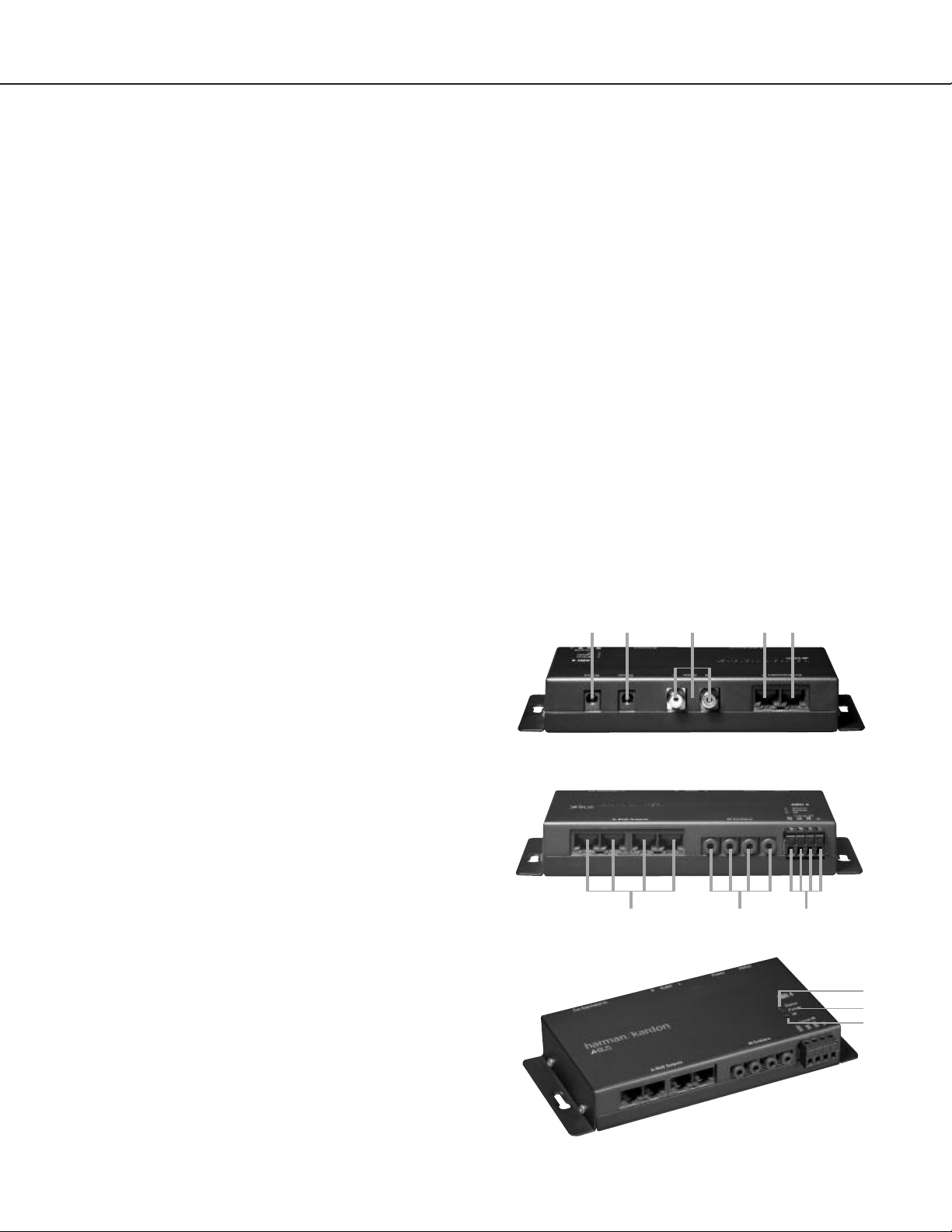
¡ (number in a circle) Indicates a connection point on the side edges of
he ABH 4.
t
å (letter in a circle) Indicates an LED indicator on the top face of the ABH 4.
Top-Edge Connections
¡ Status Input: When the ABH 4 is used in the stand-alone mode with a
non-A-BUS/
READY source or receiver, an optional 12-volt DC power source
may be attached to this jack to keep the A-BUS system active.
™ Power Input: Connect the small mini plug at the end of the ABH 4 power
supply to this jack.
£ Audio Inputs: When the ABH 4 is used in the stand-alone mode to create
A-BUS system using a receiver that is not A-BUS/
an
connect the right
EADY
R
,
and left audio outputs from the feed source to these input jacks. The source may
be a single product such as a tuner or CD player, or it may be the Tape outputs
or Multiroom outputs of a receiver. Note that these inputs are connected to Music
Sense circuitry that will automatically turn on all A-BUS modules connected to the
ABH 4 when an audio signal is present, and turn them off 30 seconds after the
audio signal stops.
¢ Expansion In Jack: This jack connects to the device that is providing
the A-BUS system source that feeds the A-BUS modules used with this
ABH 4. In most applications, the connection will be to the A-BUS output on a
Harman Kardon A-BUS/
READY receiver, although the input may also come from
the Expansion Out Jack ∞ of another ABH 4 when multiple hubs are in use.
In all cases, the connection should be made using a standard TIA 568A RJ-45
jumper cable.
∞ Expansion Out Jack: If you are using more than one ABH 4 in your sys-
tem to add additional rooms, connect one end of a jumper cable with RJ-45
connectors to this jack. Connect the other end of the jumper cable to the
Expansion In Jack ¢ on the next ABH 4.
• A-BUS Outputs: These jacks are the communications link between the
remote A-BUS modules and the ABH 4, carrying audio signals and power to the
-BUS modules, and IR commands from the A-BUS modules to the ABH 4 and
A
products connected to it. Connect a cable from each remote A-BUS module to
hese outputs using standard RJ-45 connectors with cabling wired in compliance
t
with the TIA 568A standard.
LED Indicators
å Status Indicator: This LED will light when the ABH 4 is activated. In most
cases, it will light when a Harman Kardon A-BUS/
the ABH 4 is turned on. When the ABH 4 is used with non-A-BUS/
READY receiver connected to
READY prod-
ucts, the Status Indicator will light when an audio signal is present at the Audio
Inputs £ or when a DC power source is connected to the Status Input ¡.
The Status Indicator will go out 30 seconds after the power or audio source is
removed.
∫ Power Indicator: This LED will light to indicate that the ABH 4 is con-
nected to a power source that enables the remote modules and the infrared
relay system to operate. This power source may be either a connection to an
A-BUS/READY product, the ABH 4’s power supply or through a connection to
another ABH 4. Note that the ABH 4’s external power supply must be connected
in order for it to power multiple remote modules.
ç IR Indicator: This LED will flash to confirm that an IR signal is being passed
through the ABH 4. This signal may originate from a remote A-BUS module or
from an optional remote sensor attached to the Local IR Input Terminals §.
Bottom-Edge Connections
§ Local IR Input Terminals: When the ABH 4 is used with a source product
other than an A-BUS/R
optional IR receiver/sensor to receive infrared remote commands for
compatible
,
EADY
the control of source components in a room where there is no
these terminals allow you to connect a
receiver,
A-BUS module.
IR commands received by the sensor will be retransmitted to the IR Emitter
ollow the instructions packed with
F
Jacks ¶ for use with optional IR emitters
.
the IR receiver/sensor for the proper connections to the terminals here. To connect wires from the sensor
unscrew the retaining screw on the appropriate ter
,
minal until wire clamp retracts into the bottom of the ter
wires following the instructions in Step Seven on the other side of this sheet, and
tighten the screw until the clamp secures the wire so that it does not fall out.
R Emitter Jacks:
¶ I
These jacks route the IR signals that are received either
minal block.
-
Insert the
by the remote sensor in an A-BUS module such as Harman Kardon’s AB 1 or
from an optional IR receiver connected to the Local IR Input Terminals § to
These emitters should be placed over the IR receiver
optional
remote IR emitters
in the source components to be controlled in accordance with their manufacturer’s
instructions. This enables a remote control where an A-BUS module is installed
to control source components such as a CD or DVD player
.
.
2
Page 4

INSTALLATION AND CONNECTION
Important Safety Note:
Before beginning the installation process, make certain that all electronics
products in the system are turned off and disconnected from their A/V power
onnection. This avoids the possibility of accidental activation that could possibly
c
damage the equipment or cause personal injury. Do not turn on the equipment
until instructed.
The ABH 4 may be used in two modes of operation. The installation process will
vary according to which option you select.
• When used in conjunction with an A-BUS/
READY Harman Kardon receiver,
the ABH 4 provides the power that enables up to four remote rooms to be
equipped with A-BUS modules such as the Harman Kardon AB 1, with more
room installations possible through the use of additional ABH 4 hubs.
• The ABH 4 may also be used with any receiver, preamplifier or surround
processor that that has a “tape” or “multiroom” output to send the selected
source to A-BUS modules installed in remote rooms. Alternatively, a Tuner or
CD player may be connected to the ABH 4 to create a one-source multiroom
audio system.
Mounting the ABH 4 (optional)
Before making any connections to the ABH 4, read the instructions below and
carefully plan the placement of any wiring that may be required. The ABH 4 may
be mounted on a wall using the screw slots provided on the sides of the unit, or
it may simply be placed on any flat surface.
• To mount the ABH 4 to a wall, first place the unit against the surface to which
it will be mounted, and make certain that there is sufficient clearance at all
sides for any cables that will be attached and that they are able to reach their
destination.
• Although the ABH 4 is relatively light, make certain that the wall surface is able
to support the ABH 4.
• While holding the ABH 4 to the wall, trace the outline of the slots on the
“wings” at the left and right side of the ABH to the wall.
Drill a pilot hole and install an anchor or retaining socket sufficient to accom-
•
modate a #10 pan-head Phillips-type wood screw that is at least 1 inch long
t each side, under the circular part of the tracing. If you have any questions or
a
doubt about the ability of the wall surface to properly support the weight of the
ABH 4, consult a properly trained installer before proceeding.
• When the anchor is installed, place a screw through the slot on either side
of the ABH 4 and then tighten the screw into the anchor until it is almost
completely secured.
• Slip the ABH 4 so that it slides down the keyhole notch of the slot and then
tighten it securely to the wall.
Connections to an A-BUS/READY Receiver
Step One: Connect the ABH 4 to the Receiver
Using the RJ-45 jumper cable supplied with the ABH 4, connect one end to the
Expansion In Jack ¢ on the ABH 4 and the other end to the A-BUS/READY
jack on the rear panel of your Harman Kardon receiver.
Step Two: Connect the A-BUS Modules
Connect the RJ-45 jacks on the Cat. 5 cabling that runs to the remote room
modules to the
A-BUS Outputs • on the ABH 4. Make certain that the con-
nector is wired in accordance with the standard TIA 568A color-coding. Connect
the A-BUS modules in the remote rooms to the Cat. 5 cable in accordance with
the instructions for the module.
Step Three: Connect the AC Power Supply
Connect the AC Power Supply furnished with the ABH 4 to the Power Input
™. Plug the AC power cord into the socket on the Power Supply. Do not
connect the power cord to an AC outlet at this time.
Optional Step Four: Multiple ABH 4 Connections
If you are using more than one ABH 4 in a system, connect the Expansion Out
Jack ∞ to the Expansion In Jack ¢ on another ABH 4, using the RJ-45
jumper cable supplied with the second ABH 4. Then, follow steps two and three,
as shown above.
3
Page 5

Optional AB 1
A-BUS
modules
connected
by Cat. 5 cabling
When using an A-BUS/
READY product,
use the supplied RJ-45 jumper cable
to connect the A-BUS jack on the
receiver to the “Expansion In” jack
on the ABH 4.
DVD player or other source component with
connection to compatible IR input jack
Source component
with optional IR emitter
placed over IR sensor
ABH 4
power supply
240240
31
FL 8385
P
ower Phones Phones Level
PLAY/PAUSE
1 23
4 5
DISK SKIP
STOP
S
EARCH SKIP
››ÍÍ‹‹››‹‹
4
Page 6

Connections to a Non-A-BUS/READY Product
The ABH 4 may also be used to bring the benefits of A-BUS technology to
audio systems that are not A-BUS/READY. To do this, a few additional steps are
equired to connect an audio feed and to install any required infrared emitters
r
that are used to control the source equipment. Although this installation is relatively simple, you may wish to have it completed by a trained installer who is
familiar with A-BUS and audio/video systems integration.
Step One: Connect an Audio Source
Connect the audio outputs of the source that will be used to feed the A-BUS
modules by using a standard audio interconnect cable (not included) connecting
the Audio Inputs £ on the ABH 4 to the audio outputs of the source device.
The source may be the tape outputs of a stereo preamplifier or receiver, the tape
outputs or multiroom outputs of an audio/video receiver or surround processor,
or it may be a direct connection to a single source such as a CD player or tuner.
Step Two: Connect the A-BUS Modules
Connect the RJ-45 jacks on the Cat. 5 cabling that runs to the remote room
modules to the A-BUS Outputs • on the ABH 4. Make certain that the connector is wired in accordance with the standard TIA 568A color-coding. Connect
the A-BUS modules in the remote rooms to the cable in accordance with the
instructions for the module.
Step Three: Connect the AC Power Supply
Connect the AC Power Supply furnished with the ABH 4 to the Power Input
™. Plug the AC power cord into the socket on the Power Supply. Do not
connect the power cord to an AC outlet at this time.
Optional Step Four: Multiple ABH 4 Connections
If you are using more than one ABH 4 in a system, connect the Expansion Out
Jack ∞ to the Expansion In Jack ¢ on another ABH 4, using the RJ-45
jumper cable supplied with the second ABH 4. Then, follow steps two and three
as shown above.
NOTE: The following steps provide additional options that extend the flexibility of
your A-BUS system. If you are not familiar with audio/video systems installations,
you may wish to have them completed by a properly trained installer.
Optional Step Five: Status Power Connection
If your system requires that the remote A-BUS models are active and able to
receive commands when the host receiver, processor or preamplifier is not
urned on, connect an optional power supply to the Status Input ¡.The
t
power supply is the small type typically used to power portable electronics
products and should provide a nominal 12 volts DC at 200 mA, using a
standard 2.1 plug with “Center Positive”.
Optional Step Six: Connect IR Emitters
If you are not using direct IR control connections to “IR In” jacks on products
by Harman Kardon and wish to control a receiver, processor or preamp, or a
source product such as a CD or DVD player, connect optional IR emitters to the
IR Emitter Jacks ¶ and then place them over the IR sensor on the front
panel of the unit to be controlled in accordance with the emitter manufacturer’s
instructions.
Optional Step Seven: Remote IR Sensor Connection
If the source and control equipment is behind cabinet doors or dark glass and
you wish to have an optional IR sensor in the main listening room control those
, connect that sensor (not included) to the
products
Local IR Input
Terminals
§. To make the installation easier, the black connector block may be removed
by grasping the top and bottom of the block and pulling it out toward you.
Reinstall it after the connections are made by simply pushing it back into the
socket.
When using an optional IR receiver (not supplied) the connections are as follows:
ABH 4 “Local IR”
Connection Point Sensor Connection Point
V+ +12V
SIG IR OUT
GND GND
NOTE: The STAT connection is not used in standard installations.
If you are not familiar with the use of external IR sensors in systems integration
applications, we strongly recommend that a trained custom installer perform the
installation.
5
Page 7

Optional AB 1
A-BUS
modules
connected
by Cat. 5
cabling
When using the ABH 4 with
non-A-BUS/
READY
receivers,
connect either the Multiroom outputs
(if available) or the Tape outputs to
the Audio Input ¢ jacks on the ABH 4.
DVD player or other source component with
connection to compatible IR input jack
Connect to either the Multiroom
or the Tape outputs, but not both.
Optional
IR sensor
Optional 12V
power supply
240240
31
FL 8385
Power Phones Phones Level
PLAY/PAUSE
1
23
45
D
ISK SKIP
STOP
SEARCH SKIP
››ÍÍ‹
‹››‹‹
Source component with optional
IR emitter placed over IR sensor
ABH 4
power supply
6
Page 8

Operation
¡™ £
¢
∞
¡™ £
¢
∞
§
¶•
å
∫
ç
¡™ £
¢
∞
å
∫
ç
When the installation is complete and all connections have been made to the
ABH 4 and receiver, processor or preamplifier, and the A-BUS modules have
been properly installed in the remote rooms, operation of the ABH 4 is simple.
There are no user controls on the ABH 4.
After checking the connections, plug the AC power cord from the ABH 4’s Power
Supply into a non-switched AC outlet and turn on the host receiver, processor or
preamplifier. Operation of the ABH 4 is seamless, as the remote A-BUS modules
will communicate directly with the host source.
When the ABH 4 is used with an A-BUS/
READY receiver, the A-BUS modules in
the remote room operate as if they were connected directly to the host receiver.
No further controls are needed. Follow the instructions included with the A-BUS
modules for operation information.
When the ABH 4 is used in the stand-alone mode with a source that is not
READY, the method of operation varies depending on the specifics of the
A-BUS/
installation:
• When a 12-volt adaptor is not connected to the ABH 4’s Status Input ¡,
the system is able to pass through IR commands from the remote modules
to turn on the host receiver, processor or preamplifier, but there is no power
to a remote module’s internal amplifier until an audio signal is sensed at the
ABH 4’s Audio Inputs £.
• When a 12-volt adaptor is connected to the ABH 4’s Status Input ¡, the
system is ready for full operation at all times, including pass-through of IR
commands from remote A-BUS modules as well as power to the remote
modules’ internal amplifiers.
The three LED indicators on the ABH 4 signify the following operational modes:
Status Indicator å lights when the system is activated either by con-
• The
nection to an A-BUS/READY receiver that is turned on, when a signal is sensed
Audio Inputs £ or when a 12-volt power source is connected to the
at the
Status Inputs ¡. This light indicates that the remote modules are active and
ready to accept and transmit commands.
Power Indicator ∫ lights when the AC Power Supply is connected to
• The
the ABH 4 and/or when a connection is made between the ABH 4 and an
A-BUS/READY receiver. This light indicates that the system is powered on and
is operational.
• The IR Indicator ç flashes whenever an IR command is transmitted through
the system.
Troubleshooting Guide
If the remote A-BUS modules do not operate at all:
erify all connections between the remote modules and the ABH 4
V
•
• Check the RJ-45 connection between the ABH 4 and the host receiver
(A-BUS/R
EADY
systems)
• Check the AC power connection at both the ABH 4’s Power jack and on
the Power Supply
If the remote module’s status LED is lit but there is no sound:
• Make certain that an active source has been selected on the host receiver
• Check the RJ-45 connection between the ABH 4 and the host receiver
(A-BUS/READY systems)
Check the audio connections between the
•
(non-A-BUS/
READY systems)
ABH 4 and the host receiver
For additional troubleshooting information and updated operational and installation hints, please visit the Product Support section of the Harman Kardon Web
mankardon.com.
site at www
.har
Specifications
ABH 4 Dimensions (D x W x H):
3-5/16" x 7-3/16" x 1-3/16" (83mm x 184mm x 30mm)
eight: 0.9 lb (410g)
W
ower Supply Dimensions (D x W x H):
P
2-13/16" x 5-15/16" x 1-7/16" (70mm x 151mm x 36mm)
Weight: 1 lb (450g)
Power Supply Input: 108 – 264 VAC, 115 watts
Power Supply Output: 24-volt, 4-amp supply included
Status Power: 12 volts, 200ma
Wiring protocol for A-BUS connections: TIA wiring specification for TIA 568A
Top-Edge Connections
¡ Status Input
™ Power Input
£ Audio Inputs
¢ Expansion In Jack
∞ Expansion Out Jack
Bottom-Edge Connections
§ Local IR Input Terminals
¶ IR Emitter Jacks
• A-BUS Outputs
LED Indicators
tus Indica
å Sta
∫ Power Indicator
ç IR Indicator
tor
7
Page 9

, Woodbury, New York 11797
250 Crossways P
516.422.HKHK (4545) F
© 2005 Harman International Industries, Incorporated. All rights reserved.
Printed 3/05 Part No. ABO 42hl
Harman Kardon and Power for the Digital Revolution are registered trademarks of Harman International Industries, Incorporated.
A-BUS and A-BUS/
All features and specifications are subject to change without notice.
ark Drive
516.682.3523
ax:
READY are registered trademarks of LeisureTech Electronics Pty Ltd.Australia.
 Loading...