

Page 1
Complete Equalization & Loudspeaker Management System
4800/4820
User Manual
Page 2
IMPORTANT SAFETY INSTRUCTIONS
WARNING FOR YOUR PROTECTION READ THESE INSTRUCTIONS:
CAUTION
RISK OF ELECTRIC SHOCK
DO NOT OPEN
ATTENTION:
WARNING:
SHOCK DO NOT EXPOSE THIS EQUIPMENT TO RAIN OR MOISTURE
RISQUE DE CHOC ELECTRIQUE - NE PAS OUVRIR
TO REDUCE THE RISK OF FIRE OR ELECTRIC
The symbols shown above are internationally
accepted symbols that warn of potential hazards
with electrical products. The lightning flash with
arrowpoint in an equilateral triangle means that
there are dangerous voltages present within the
unit. The exclamation point in an equilateral triangle indicates that it is necessary for the user to
refer to the owner’s manual.
These symbols warn that there are no user serviceable parts inside the unit. Do not open the unit.
Do not attempt to service the unit yourself. Refer
all servicing to qualified personnel. Opening the
chassis for any reason will void the manufacturer’s
warranty. Do not get the unit wet. If liquid is
spilled on the unit, shut it off immediately and take
it to a dealer for service. Disconnect the unit during storms to prevent damage.
SAFETY INSTRUCTIONS
NOTICE FOR CUSTOMERS IF YOUR UNIT IS EQUIPPED
WITH A POWER CORD.
WARNING: THIS APPLIANCE MUST BE EARTHED.
CONNECT ONLY TO A MAINS SOCKET OUTLET WITH
PROTECTIVE EARTHING CONNECTION.
The cores in the mains lead are coloured in accordance with
the following code:
GREEN and YELLOW - Earth BLUE - Neutral BROWN - Live
As colours of the cores in the mains lead of this appliance may
not correspond with the coloured markings identifying the
terminals in your plug, proceed as follows:
• The core which is coloured green and yellow must be connected to the terminal in the plug marked with the letter E, or
with the earth symbol, or coloured green, or green and yellow.
• The core which is coloured blue must be connected to the
terminal marked N or coloured black.
• The core which is coloured brown must be connected to the
terminal marked L or coloured red.
This equipment may require the use of a different line cord,
attachment plug, or both, depending on the available power
source at installation. If the attachment plug needs to be
changed, refer servicing to qualified service personnel who
should refer to the table below. The green/yellow wire shall
be connected directly to the units chassis.
CONDUCTOR
LIVE
L
NEUTRAL
N
E
EARTH GND
WARNING: If the ground is defeated, certain fault conditions
in the unit or in the system to which it is connected can result
in full line voltage between chassis and earth ground. Severe
injury or death can then result if the chassis and earth ground
are touched simultaneously.
WIRE COLOR
Normal Alt
BROWN
BLUE
GREEN/YEL
BLACK
WHITE
GREEN
KEEP THESE INSTRUCTIONS
HEED ALL WARNINGS
FOLLOW ALL INSTRUCTIONS
THE APPARATUS SHALL NOT BE EXPOSED TO DRIPPING OR SPLASHING LIQUID
AND NO OBJECT FILLED WITH LIQUID, SUCH AS VASES, SHALL BE PLACED ON
THE APPARATUS.
CLEAN ONLY WITH A DRY CLOTH.
DO NOT BLOCK ANY OF THE VENTILATION OPENINGS. INSTALL IN ACCORDANCE
WITH THE MANUFACTURER’S INSTRUCTIONS.
DO NOT INSTALL NEAR ANY HEAT SOURCES SUCH AS RADIATORS, HEAT
REGISTERS, STOVES, OR OTHER APPARATUS (INCLUDING AMPLIFIERS) THAT
PRODUCE HEAT.
ONLY USE ATTACHMENTS/ACCESSORIES SPECIFIED BY THE MANUFACTURER.
UNPLUG THIS APPARATUS DURING LIGHTNING STORMS OR WHEN UNUSED
FOR LONG PERIODS OF TIME.
Do not defeat the safety purpose of the polarized or grounding-type
plug. A polarized plug has two blades with one wider than the other. A
grounding type plug has two blades and a third grounding prong. The
wide blade or third prong are provided for your safety. If the provided
plug does not fit your outlet, consult an electrician for replacement of
the obsolete outlet.
Protect the power cord from being walked on or pinched particularly
at plugs, convenience receptacles, and the point where they exit from
the apparatus.
Use only with the cart stand, tripod bracket, or table specified by the
manufacture, or sold with the apparatus. When a cart is used, use
caution when moving the cart/apparatus combination to avoid injury
from tip-over
Refer all servicing to to qualified service personnel. Servicing is
required when the apparatus has been damaged in any way, such as
power-supply cord or plug is damaged, liquid has been spilled or objects
have fallen into the apparatus, the apparatus has been exposed to rain
or moisture, does not operate normally, or has been dropped.
POWER ON/OFF SWITCH: For products provided with a power switch, the
power switch DOES NOT break the connection from the mains.
MAINS DISCONNECT: The plug shall remain readily operable. For rackmount or installation where plug is not accessible, an all-pole mains
switch with a contact separation of at least 3 mm in each pole shall
be incorporated into the electrical installation of the rack or building.
FOR UNITS EQUIPPED WITH EXTERNALLY ACCESSIBLE FUSE RECEPTACLE:
Replace fuse with same type and rating only.
MULTIPLE-INPUT VOLTAGE: This equipment may require the use of a different line cord, attachment plug, or both, depending on the available
power source at installation. Connect this equipment only to the power
source indicated on the equipment rear panel. To reduce the risk of
fire or electric shock, refer servicing to qualified service personnel
or equivalent.
This Equipment is intended for rack mount use only.
If connected to 240V supply, a suitable CSA/UL certified power cord shall
be used for this supply.
Page 3
IMPORTANT SAFETY INSTRUCTIONS
If you want to dispose this product, do not mix it with general household waste. There is a
separate collection syst em fo r used el ectronic products in accordance with legislation tha t
requires proper treatment, recovery and recycling.
Private household in the 25 member states of the EU, in Switzerland and Norway may return their used
electronic products free of charge to designated collection facilities or to a retailer (if you purchase a similar
new one).
For Countries not mentioned above, please contact your local authorities for a correct method of disposal.
By doing so you will ensure that your disposed product undergoes the necessary treatment, recovery and
recycling and thus prevent potential negative effects on the environment and human health.
DECLARATION OF
ELECTROMAGNETIC
COMPATIBILITY
This device complies with part 15 of the
FCC Rules and the Product Specifications
noted on the Declaration of Conformity.
Operation is subject to the following two
conditions:
• this device may not cause harmful
interference, and
• this device must accept any interference received, including interference
that may cause undesired operation.
Operation of this unit within significant
electromagnetic fields should be avoided.
Manufacturer’s Name: dbx Professional Products
Manufacturer’s Address: 8760 S. Sandy Parkway
Sandy, Utah 84070, USA
declares that the product:
Product name: dbx 4800, 4820
Note: Product name may be suffixed by the
EU.
Product option: None
conforms to the following Product Specifications:
Safety: IEC 60065 -01+Amd 1
EMC: EN 55022:2006
EN 55024:1998
FCC Part 15
CONFORMITY
• use only shielded interconnecting
cables.
U.K. MAINS PLUG WARNING
A molded mains plug that has been cut off from the cord
is unsafe. Discard the mains plug at a suitable disposal
facility. NEVER UNDER ANY CIRCUMSTANCES SHOULD YOU
INSERT A DAMAGED OR CUT MAINS PLUG INTO A 13 AMP
POWER SOCKET. Do not use the mains plug without the
fuse cover in place. Replacement fuse covers can be
obtained from your local retailer. Replacement fuses
are 13 amps and MUST be ASTA approved to BS1362.
Supplementary Information:
The product herewith complies with the require
ments of the:
Low Voltage Directive 2006/95/EC
EMC Directive 2004/108/EC.
RoHS Directive 2002/95/EC
WEEE Directive 2002/96/EC
With regard to Directive 2005/32/EC and EC
Regulation 1275/2008 of 17 December 2008,
this product is designed, produced, and classified
as Professional Audio Equipment and thus is
exempt from this Directive.
Roger Johnsen
Director, Engineering
Signal Processing
8760 S. Sandy Parkway
Sandy, Utah 84070, USA
Date: December 8, 2010
European Contact: Your local dbx Sales and Service
Office or
Harman Music Group
8760 South Sandy Parkway
Sandy, Utah
84070 USA
Ph: (801) 566-8800
Fax: (801) 568-7583
Page 4

Table of Contents
®
DriveRack
Introduction
0.1 DriveRack 4800/4820 Features .............................ii
0.2 Service Contact Info ............................................iii
0.3 Warranty .............................................................. iii
Section 1 - Getting Started
1.1 Rear Panel 4800/4820 ..........................................2
1.2 Front Panel (4800) ................................................3
1.3 Front Panel (4820) ...............................................5
1.4 System Architect Control Software .......................6
Section 2 - DriveRack 4800/4820
Philosophy
2.1 DriveRack 4800/4820 Philosophy ...................... 10
Section 3 - Front Panel Operation
3.1 Navigation ..........................................................12
3.2 Modes of Operation ............................................13
Section 4 - Software Operation
4.1 DriveRack Philosophy.........................................20
4.2 System Architect DriveRack 4800/4820
File Storage .........................................................20
4.3 System Architect DriveRack 4800/4820
Philosophy ..........................................................20
4.3.1 Module View .................................................. 20
4.3.2 Device Window ............................................... 21
4.3.3 Venue View .....................................................25
Section 5 - In Use
5.1 Front Panel Operation ........................................ 32
5.2 GUI Operation ................................................... 36
Section 6 - Detailed Parameters
6.1 Input Mixer ........................................................40
6.2 Input Router ....................................................... 41
6.3 Input Graphic EQ ..............................................42
6.4 Input 9-Band Parametric EQ .............................. 43
6.5 Input Delay.........................................................44
6.6 Output Mixer .....................................................45
6.7 Output Router .................................................... 46
6.8 Output Bandpass Filter/Crossover ......................47
6.9 Output 6-Band Parametric EQ ........................... 48
6.10 Output Delay....................................................49
6.11 Advanced Feedback Suppression (AFS®) Insert . 50
6.12 Automatic Gain Control (AGC) Insert ............. 52
6.13 AutoWarmth
6.14 Compressor Insert ............................................. 55
6.15 De-Esser Insert ..................................................57
6.16 Noise Gate ........................................................ 58
6.17 Limiter Insert .................................................... 59
6.18 Notch Filter Insert ............................................ 61
6.19 SubHarmonic Synthesizer Insert ....................... 62
®
Insert ......................................... 54
Section 7 - Utilities
7.1 Miscellaneous ...................................................... 64
7.2 Gains and Trims ................................................. 64
7.3 Sample Rate ........................................................ 64
7.4 Real Time Clock ................................................. 65
7.5 Access Rights.......................................................65
7.6 Users ................................................................... 65
7.7 Preset Range .......................................................65
7.8 Network ..............................................................65
Table of Contents
DriveRack® 4800/4820 User Manual
Page 5

®
DriveRack
Appendix
A.1 Specifications ...................................................... 68
A.2 Block Diagram ...................................................70
A.3 Preset Table ........................................................ 71
A.4 Crossover Table .................................................. 71
A.5 Digital I/O and Clocking ................................... 72
A.6 Word Clock Termination ...................................72
A.7 Zone Controller Wiring and Installation ............ 73
A.8 ZC-4 Wiring Diagram .......................................76
A.9 Factory Reset ...................................................... 77
A.10 Ethernet Networking ........................................ 78
A.10.1 Overview of TCP/IP Address ........................78
A.10.2 Connecting the Computer Directly
to the DriveRack ........................................... 79
A.10.3 Setup of a Simple Isolated Ethernet
Network Using DHCP ................................. 80
A.10.4 Proxy ............................................................. 80
A.10.5 Virtual Private Networks (VPN) ...................81
A.10.6 Network Considerations and Limitations ...... 81
A.10.7 Network Troubleshooting ............................. 82
A.10.8 Copyrights ..................................................... 83
Table of Contents
DriveRack® 4800/4820 User Manual
Table of Contents
Page 6

DriveRack
®
Page 7
DriveRack
®
Introduction
INTRODUCTION
FEATURES
CUSTOMER SERVICE INFO
WARRANTY INFO
Page 8

®
INTRODUCTION
Introduction
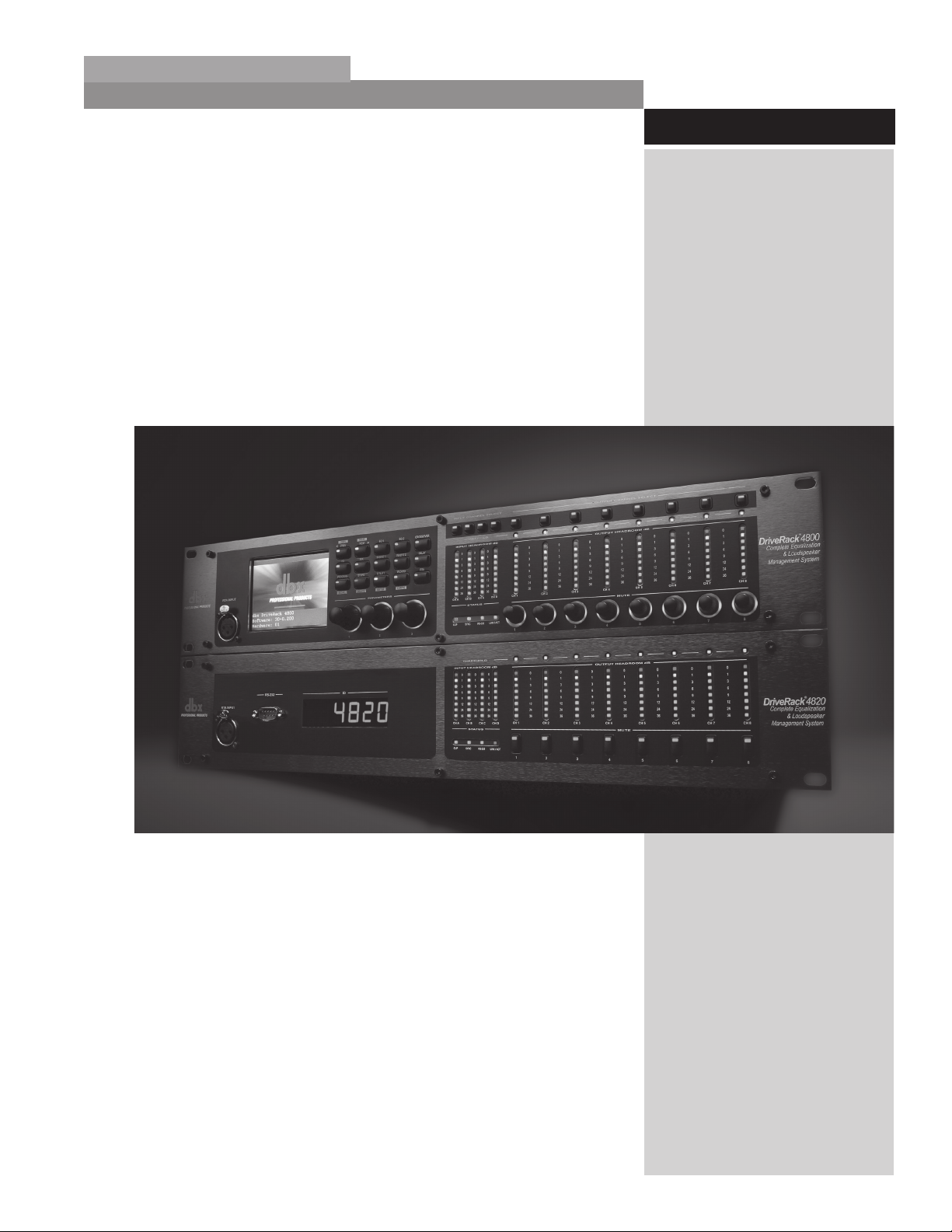
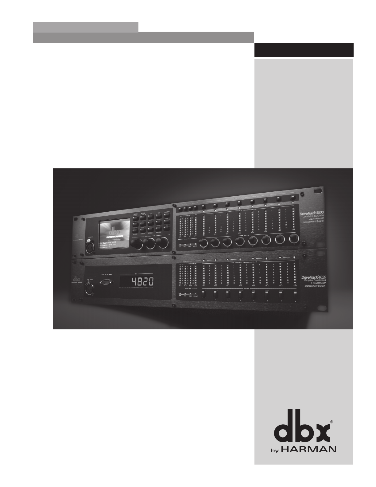
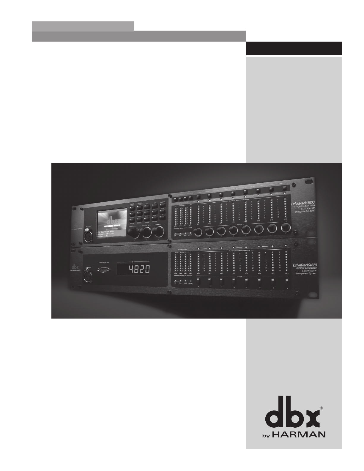
Congratulations on your purchase of the dbx® DriveRack® 4800 or 4820 system processor! Designed
to provide “Everything you need between the mixer and the power amps,” the 4800 and 4820 provide
incredible flexibility, sonic excellence, and intuitive control for performance applications. From the powerful 96kHz processing engine and advanced processing algorithms, to the VGA display and direct access
Processing and Channel buttons, the DriveRack 4800 provides all the processing and control you need
for live use. The 4820 offers all the DSP functionality of the 4800 with a tamper-proof front panel for
installation use. Some of the many features of the 4800 and 4820 include:
DriveRack
0.1 - DriveRack 4800/4820 Features
• 48 and 96 kHz operation
• Color 1/4 VGA (320x240) Display (4800)
• 4 analog and AES/EBU digital inputs
• 8 analog and AES/EBU digital outputs
• Full Bandpass Filter, Crossover and Routing Configurations with
Bessel, Butterworth, and Linkwitz-Riley filters
• 31-Band Graphic and 9-band Parametric EQ on every input
• 6-band Parametric EQ on every output
• Loudspeaker Cluster and Driver Alignment Delays
• Selectable DSP inserts on all inputs and outputs including
Classic dbx Compression, Limiting and Advanced Feedback
Suppression among others
• Ethernet HiQnet networking and control
• Optional dbx ZC wall panel control
• Optional CobraNet I/O
®
• Optional Jensen
I/O Transformers
ii
DriveRack® 4800/4820 User Manual
Page 9

®
DriveRack
Introduction
0.2 - Service Contact Info
If you require technical support, contact dbx Customer Service. Be prepared to accurately describe the
problem. Know the serial number of your unit - this is printed on a sticker attached to the top panel. If you
have not already taken the time to fill out your warranty registration card and send it in, please do so now.
Before you return a product to the factory for service, we recommend you refer to the manual. Make sure
you have correctly followed installation steps and operation procedures. If you are still unable to solve
a problem, contact our Customer Service Department at (801) 568-7660 for consultation. If you need
to return a product to the factory for service, you MUST contact Customer Service to obtain a Return
Authorization Number.
No returned products will be accepted at the factory without a Return Authorization Number. Please refer
to the Warranty information on the following page, which extends to the first end-user. After expiration of
the warranty, a reasonable charge will be made for parts, labor, and packing if you choose to use the factory
service facility. In all cases, you are responsible for transportation charges to the factory. dbx will pay return
shipping if the unit is still under warranty.
Use the original packing material if it is available. Mark the package with the name of the shipper and with
these words in red: DELICATE INSTRUMENT, FRAGILE! Insure the package properly. Ship prepaid,
not collect. Do not ship parcel post.
0.3 - Warranty
This warranty is valid only for the original purchaser and only in the United States.
1. The warranty registration card that accompanies this product must be mailed within 30 days after purchase date to validate this warranty. Proof-of-purchase is considered to be the burden of the consumer.
2. dbx warrants this product, when bought and used solely within the U.S., to be free from defects in
materials and workmanship under normal use and service.
3. dbx liability under this warranty is limited to repairing or, at our discretion, replacing defective
materials that show evidence of defect, provided the product is returned to dbx WITH RETURN
AUTHORIZATION from the factory, where all parts and labor will be covered up to a period of two
years. A Return Authorization number must be obtained from dbx by telephone. The company shall not
be liable for any consequential damage as a result of the product’s use in any circuit or assembly.
4. dbx reserves the right to make changes in design or make additions to or improvements upon this
product without incurring any obligation to install the same additions or improvements on products
previously manufactured.
5. The foregoing is in lieu of all other warranties, expressed or implied, and dbx neither assumes nor authorizes any person to assume on its behalf any obligation or liability in connection with the sale of this
product. In no event shall dbx or its dealers be liable for special or consequential damages or from any
delay in the performance of this warranty due to causes beyond their control.
DriveRack® 4800/4820 User Manual
iii
Page 10

Introduction
®
DriveRack
iv
DriveRack® 4800/4820 User Manual
Page 11

®
DriveRack
Section 1
Getting Started
REAR PANEL
FRONT PANEL
SOFTWARE INSTALLA-
TION
Page 12
Section 1
Getting Started
®
DriveRack
1
7
89
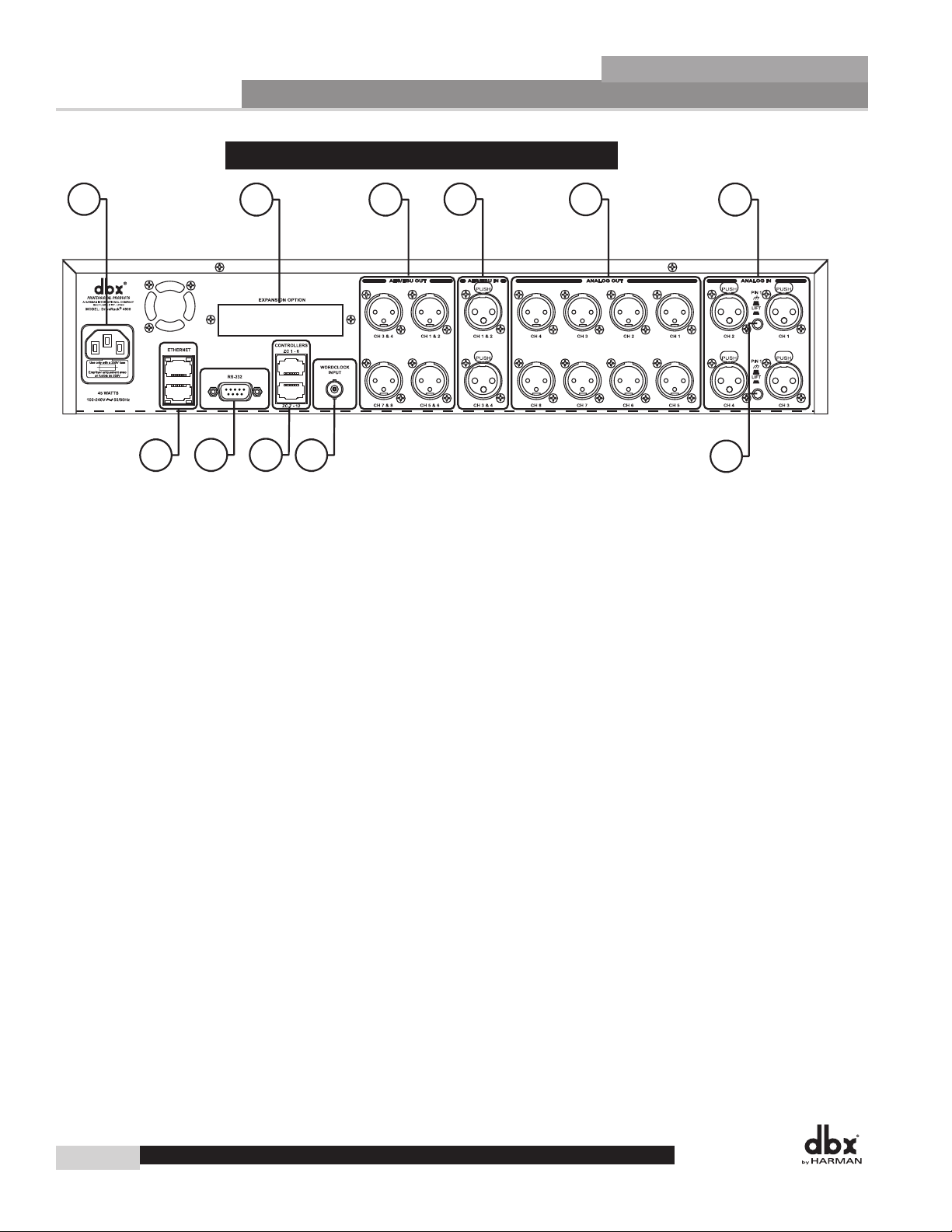
1. IEC Power Cord Receptacle
2. Optional CobraNet™ Connection (RJ-45)
1.1 - Rear Panel 4800/4820
23
4
10
The 4800 and 4820 come with a power supply that will accept voltages ranging from 100V-240V at frequencies from 50Hz-60Hz. An IEC cord is included for both a US and European style AC mains plug.
The Option Slot is for a CobraNet card that provides CobraNet audio and control networking.
5
6
11
3. Digital AES/EBU Output Channels 1-8 (XLR)
The eight AES/EBU output channels (four XLR connectors) are transformer isolated.
4. Digital AES/EBU Input Channels 1-4 (XLR)
The four digital AES/EBU input channels (two XLR connectors) are transformer isolated.
5. Analog Output Channels 1-8 (XLR)
The eight analog outputs of the 4800 and 4820 are electronically balanced and the signals sent to these
outputs are analog copies of the AES/EBU outputs. An optional Input/Output isolation transformer package is available.
6. Analog Input Channels 1-4 (XLR)
The four analog inputs of the 4800 and 4820 are electronically balanced. An optional Input/Output isolation transformer package is available.
7. Ethernet Connection (RJ-45)
These RJ-45 connections are used to network DriveRack devices and control them via Ethernet.
8. PC Connection (DB-9)
This DB-9 connection is used to communicate with the PC GUI and uses RS-232 protocol. This connection requires a Null modem cable (included with the unit).
2
DriveRack
®
4800/4820 User Manual
Page 13
®
DriveRack
9. Zone Control Inputs 1-12 (RJ-45)
These RJ-45 connections are used to receive control information from up to 12 ZC wall panel controllers.
10. Word Clock BNC Connection
This connection allows the DriveRack 4800 or 4820 to lock to a master system clock. It is not terminated. For best results we recommend using “T” connectors when setting up a BNC Word Clock network and terminating the end of of this network with a 75 ohm BNC terminator. (See Appendix 6).
11. Pin Lift Switch
Analog Inputs 1&2, and 3&4 of the DriveRack 4800/4820 share a Ground Lift Switch (Pin 1 lift).
System ground loops can cause hum; this hum can be reduced by pressing the Ground Lift Switch.
Getting Started
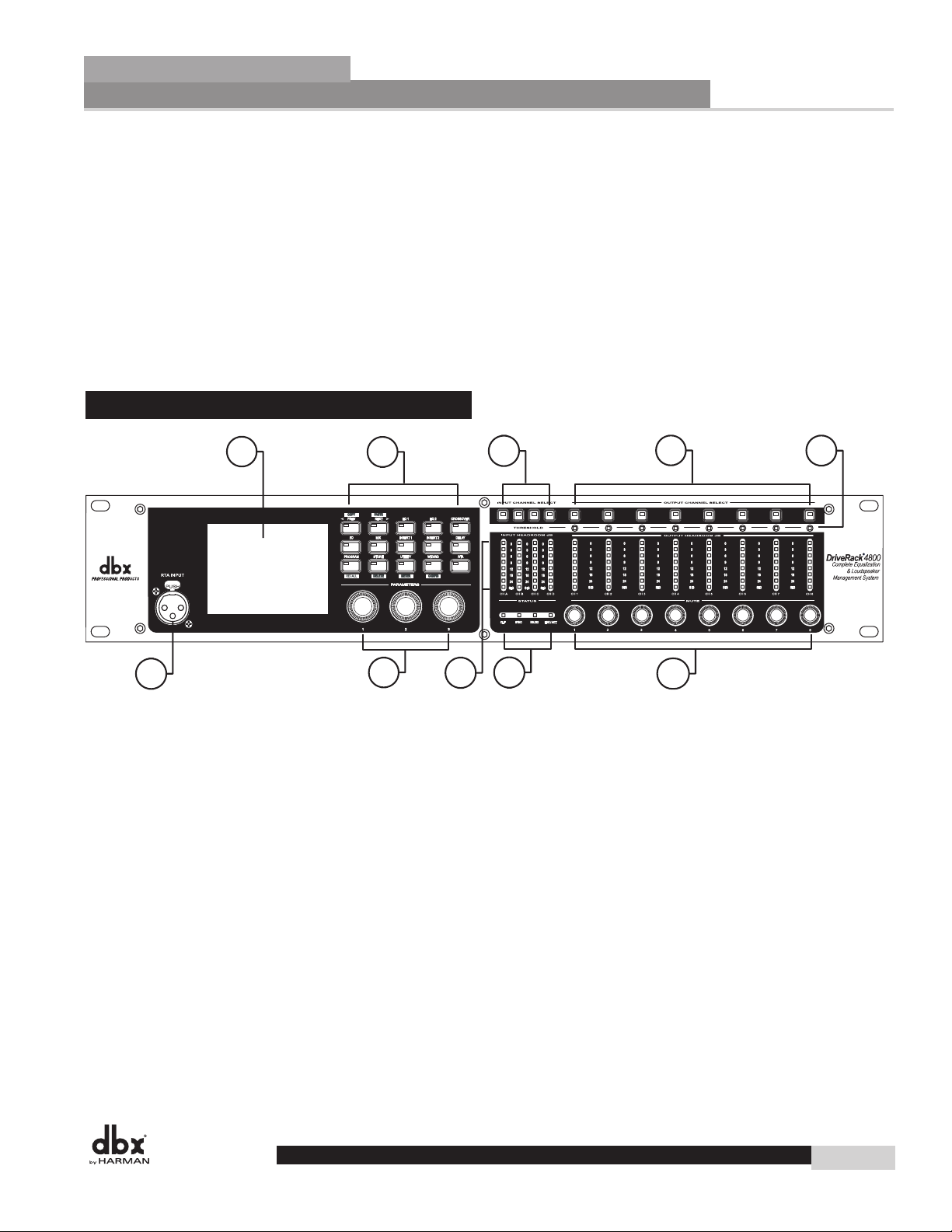
1.2 - Front Panel (4800)
Section 1
1
6
1. LCD Display
The color 1/4 VGA (320x240) display provides viewing of all parameters and attributes of the
DriveRack 4800.
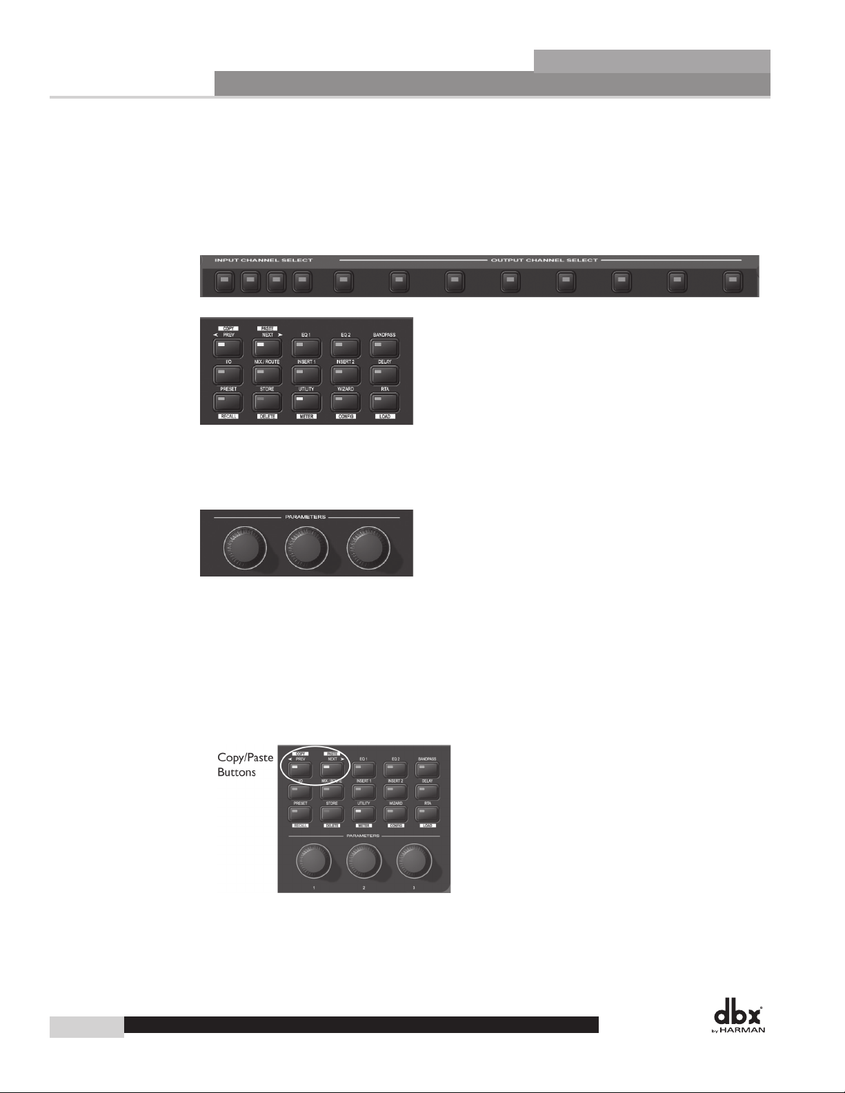
2. Function Buttons
The Function buttons of the DriveRack 4800 allow direct access to all editing and navigating functions
of the DriveRack 4800. The functions of the aforementioned buttons are as follows:
PREV is used to navigate back through the various pages of any module. Pressing and
holding the PREV button allows you to enter Copy/Paste Mode, where subsequent presses
of PREV allow copying all the function DSP parameters.
2
7
3
8
9
4
10
5
NEXT is used to navigate forward through the various pages of any module. Pressing
and holding the NEXT button allows you to enter Copy/Paste Mode, where subsequent
presses of NEXT allow pasting of all the function DSP parameters.
EQ 1 is used to select and/or enter the first Input EQ module or the Output EQ module.
EQ 2 is used to select and/or enter the second Input EQ module or the Output EQ module.
BANDPASS is used to select and/or enter the Bandpass/Crossover function.
DriveRack® 4800/4820 User Manual
3
Page 14

Section 1
Getting Started
OUTPUT is used to select and/or enter the Input and Output setup module.
ROUTE/MIX is used to select and/or enter either the Input or Output Router or Mixer
module.
INSERT 1 is used to select and/or enter the first Insert function in either the Input or
Output.
INSERT 2 is used to select and/or enter the second Insert function in either the
Input or Output.
DELAY is used to select and/or enter either the Input or Output Delay module.
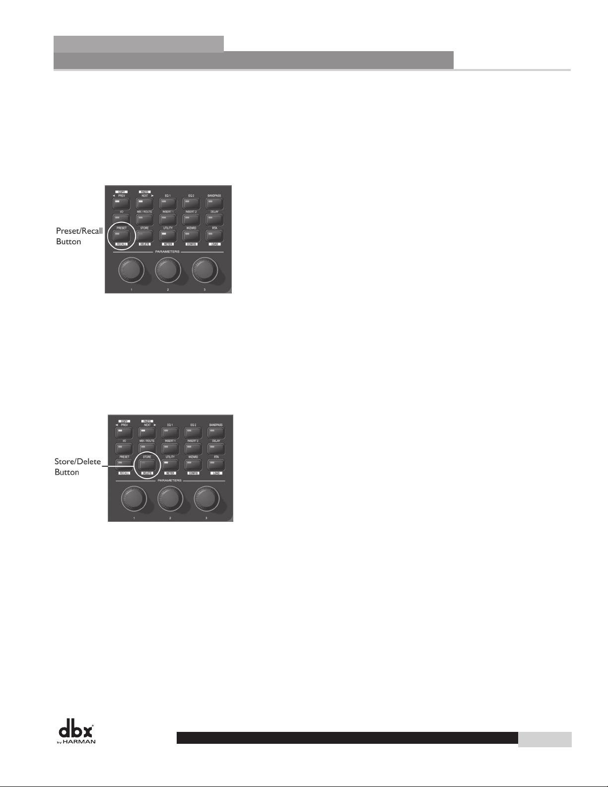
PRESET is used to return to the Preset Screen and exit out of any mode. Pressing and
holding PRESET enters Preset Recall Mode allowing selection of an alternate preset.
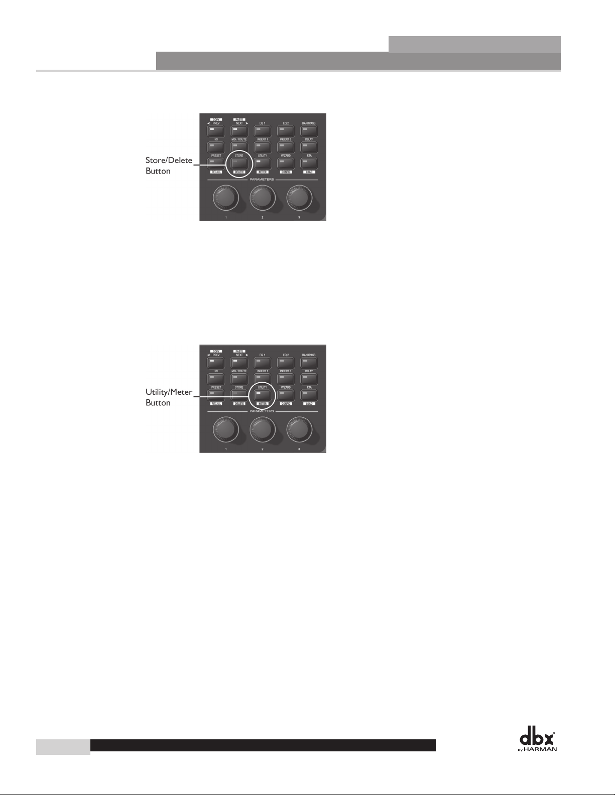
STORE is used to store any preset changes. Pressing and holding STORE lets you
Delete a preset from the preset table.
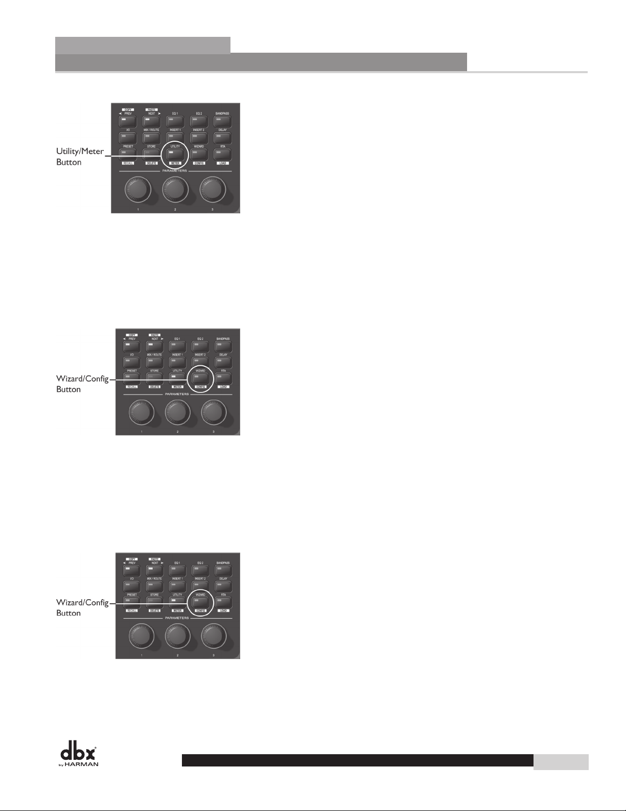
UTILITY is used to access the Utility menu. Pressing and holding UTILITY allows access
to the Meter Mode where additional metering is available.
DriveRack
®
WIZARD is used to enter the Wizard section. Pressing and holding the WIZARD button enters
Configuration Mode where changes to the preset configuration can be made.
RTA is used to view the Real Time Analyzer. In other modes (such as Preset Recall or
Configuration) pressing and holding the RTA button is used to Load those changes.
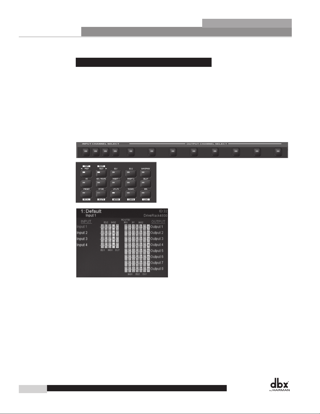
3. Input Channel Select A-D
These buttons are used to select the desired input channel.
4. Ouput Channel Select 1-8
These buttons are used to select the desired output channel.
5. Threshold Meters
The tri-color Threshold meters indicate that the threshold level has been exceeded in the Output Insert
Limiter, Compressor or Auto Gain Control.
6. RTA Input Jack
This balanced XLR input is used for the connection of an RTA microphone, which may be used with
the Auto EQ Wizard and RTA functions. 48V phantom power is always engaged on this connector.
7. Parameter Control 1-3
These three knobs are used to select and edit parameters.
8. Input Meters
The DriveRack 4800 provides you with four independent eight segment input headroom meters that
range from SIG (-48dB) to 0dB. These meters monitor the signal directly following the input section.
4
DriveRack® 4800/4820 User Manual
Page 15
®
DriveRack
9. Status LEDs
This cluster of four LEDs indicate the following functions:
CLIP - indicates either A/D, D/A, or DSP clipping.
SYNC - indicates DSP syncing to an internal clock, AES/EBU, CobraNet, or Wordclock input.
RS-232 - indicates PC connection via RS-232.
LINK/ACT - indicates connection to and/or activity on an Ethernet network.
10. Output Adjustment/Mute Knobs 1-8
The Output Trim/Mute knobs provide Trim Gain adjustment of each output. Pressing the knob
mutes that output.
11. Output Meters
The DriveRack 4800 provides eight independent eight segment output headroom meters that range from SIG
(-48dB) to 0dB.
Getting Started
Getting Started
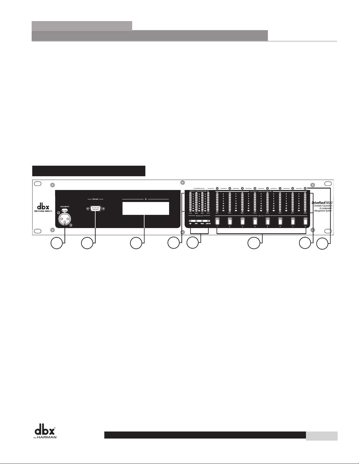
1.3 - Front Panel (4820)
Section 1
1
1. RTA Input Jack
This balanced XLR input is used for the connection of an RTA microphone, which may be used with
the Auto EQ function in the Wizard. 48V phantom power is always engaged on this connector.
2. Serial PC Connection (DB-9)
This DB-9 connection is used to communicate to the System Architect control software and uses
RS-232 protocol. This connection requires a Null Modem cable and one is included with the unit.
3. Alpha Numeric Display
This display shows the ID# of the DriveRack 4820 unit. It can also show various error codes.
4. Input Meters
The DriveRack 4820 provides four independent eight segment input headroom meters that range from
SIG (-48dB) to 0dB. These meters monitor the signal directly following the input section.
5. Status LEDs
This cluster of four LEDs indicate the following functions:
2
3
4
5
6
7
8
DriveRack® 4800/4820 User Manual
5
Page 16

Section 1
®
Getting Started
CLIP - indicates either A/D, D/A, or DSP clipping.
SYNC - indicates DSP syncing to an internal clock, AES/EBU or Wordclock input.
RS-232 - indicates PC connection via RS-232.
LINK/ACT - indicates connection to and/or activity on an Ethernet network.
DriveRack
6. Mute Buttons
The DriveRack 4820 provides a MUTE button for each output.
7. Output Meters
The DriveRack 4800 provides eight independent eight-segment output headroom meters that range from SIG
(-48dB) to 0dB.
8. Threshold Meters
The tri-color Threshold meters indicate that the threshold level has been exceeded in the Output Insert
Gate, Limiter, Compressor or Auto Gain Control.
1. 4 - System Architect Control Software
The System Architect software provides control and monitoring of the DriveRack 4800 and 4820 devices. Multiple units can be networked and controlled together along with other products from Harman
Professional. It is the only software package that allows complete control of all the links in the signal
chain from within a single application. It enables flagship products from best-in-class brands to act as
one collective consciousness, and makes real the benefits only a truly unified system can bring.
Understanding the System Architect software is the key to getting full functionality from the DriveRack
4800 and 4820 products.
System Architect Features
• Supports Ethernet control
• Supports Serial control
• Supports CobraNet audio
• Supports up to 64 channels of streaming audio
• Supports sample rates up to 96kHz
• Supports up to 65,536 HiQnet nodes in a single system
• Wireless 802.11g compatible
• Optimized for tablet PC use
• Optimized for remote access
• Universal Plug and Play compliant
• Multiple computer support
The DriveRack 4800/4820 are compatible with the following products via
System Architect
• AKG WMS 4000 wireless microphone system
• BSS Soundweb London networked audio distribution system
• Crown I-Tech tour sound amplifier range
• Crown amplifier PIP modules - Lite, USP3, USP3/CN
• JBL DP Series intelligent networked amplified speaker
• Studer Vista 8 digital production console
6
DriveRack® 4800/4820 User Manual
Page 17

®
DriveRack
Minimum System Requirements for System Architect are:
1GHz, Pentium III processor
512MB RAM
Windows 2000 or XP service pack 2
Recommended System Requirements:
3GHz, Pentium 4 processor
1GB RAM
Recommended screen resolution: 1024 x 768 pixels or higher
Installation
• Install the System Architect GUI software from either the Harman Professional website at
www.harmanpro.com or from the dbx website at www.dbxpro.com or from the included CD ROM
onto your computer.
• Once the software setup is downloaded, double click on the file named: System Architect setup.
• The application will proceed to prompt you for the installation location.
• Once the software installation has been completed, it is recommended that you restart your computer.
Note
You must disable virus protection software during the installation of the System Architect software.
Getting Started
Section 1
DriveRack® 4800/4820 User Manual
7
Page 18

Section 1
Getting Started
®
DriveRack
8
DriveRack® 4800/4820 User Manual
Page 19
®
DriveRack
Section 2
DriveRack Philosophy
PRESETS
ATTRIBUTES
Page 20

Section 2
®
DriveRack Philosophy
DriveRack
2.1 - DriveRack 4800/4820 Philosophy
The philosophy of the DriveRack 4800 and 4820 revolves around the concept of two elements: Attributes
and Presets.
Attributes
Attributes are parameters that are global like sample rate, analog I/O gain structure, or RTA microphone preamp gain. Most Attributes are found in the Utility menus. Depending on the function, Attributes are
either stored instantly as they are changed or upon exiting the Utility menus, and are stored instantly as they
are changed.
Presets
A Preset is the name given to the audio processing and routing that is occurring in the DriveRack 4800 or
4820. Up to 50 Presets can be stored in the DriveRack 4800 or 4820. The Preset can be further broken
down into two parts: the signal path (or Configuration) and the actual Parameters (listed below) found
in the individual processing functions or modules. Presets are stored manually in the DriveRack unit by
either using the STORE button on the front panel of the 4800 or by using the Preset Tool in the System
Architect software. Presets for the DriveRack 4800 or 4820 can also be saved on the PC as a preset file.
Configuration
The DriveRack 4800 and 4820 units offer two types of processing modules. The first type includes functions like EQ, Bandpass Filters, Mixers, Routers, and Delay; these functions can be linked together but are
fixed in their positions. The second type includes insertable functions that can be selected from a list in four
positions; this list includes Feedback Suppression, Compression, Noise Gate, Limiter, Notch Filter, Auto
Gain Control, AutoWarmth, etc. The process of linking modules and selecting inserts is called Configuring.
The 4800 and 4820 can be configured with hundreds of different signal routing and processing variations.
Parameters
Parameters refers to the processing function parameters. Control of any parameter can be done via the front
panel interface of the DriveRack 4800 with its Function and Channel buttons, or the System Architect
software. Some parameters, such as output gain, can be adjusted from a ZC series wall panel controller.
System Architect Software / DriveRack Plug-In
The HiQnet System Architect Graphic User Interface application (referred to hereafter as System Architect
or GUI) is the control software for the DriveRack 4800 and 4820. In addition to parameter adjustment
and all the same control as the front panel of the 4800, System Architect provides the ability to control
multiple units. The GUI can save and recall Preset files as well as a Device file that includes all the Presets
and Attributes in the unit. Besides these files types, it can also store a venue file with all the units in the
network. It can provide a wealth of additional utility like wireless control, grouping functions, custom
control panels and more; see Software Operation in Section 4.
10
DriveRack® 4800/4820 User Manual
Page 21

®
DriveRack
Section 3
Front Panel Operation
NAVIGATION
MODES
Page 22
Section 3
®
Front Panel Operation
The DriveRack 4800 is modal in its operation with different types of navigation depending on the mode
that the unit is in. For each of the modes, navigation has been optimized to ensure speed and accuracy.
DriveRack
3.1 - Navigation
The DriveRack 4800 uses three types of navigation to access system attributes and parameters, Matrix
navigation, Scroll navigation, and Page navigation. Some functions require the use of more than one type
of navigation; an example of this is the Edit mode, where a combination of Matrix navigation and Page
navigation are used to access individual parameters in the various processing modules.
Matrix Navigation - This refers to moving around the matrix, field, or grid of processing modules that are
shown on the main preset screen. Matrix navigation relies on the use of the channel and Function buttons to find the desired processing module. For example, if you were in Copy/Paste mode (see Copy/Paste
below) and wanted to copy the parameters of the Input Graphic EQ on Input B, you would simply press
the INPUT B button then the EQ1 button, and the Input Graphic EQ on input B would be highlighted.
12
DriveRack® 4800/4820 User Manual
Page 23
®
Front Panel Operation
DriveRack
Scroll Navigation - This navigation is used in the Utility menus, as well as in storing, recalling and deleting
presets. It is very useful for finding menu offerings that are located within another sub-menu. For example,
the RTA mic pre gain is located within the Gain/Trim sub-menu of the Utility.
Page Navigation - This is the easiest and most common type of navigation within the DriveRack 4800.
Page navigation is used when there are several pages of parameters that need to be accessed. An example of
Page navigation is found in the Compressor editor where there are three pages of parameters and the NEXT
and PREV PAGE buttons are used to move between these pages.
Section 3
3.2 - Modes of Operation
The standard mode of operation of the DriveRack 4800 is Edit Preset (or Edit) mode. This mode is the
gateway to all editing and is the only “location” from which all the other modes can be accessed. This
mode can be returned to from any other mode or menu by pressing the PRESET button. Pressing the
PRESET button returns you to the main preset screen that shows the signal path through the unit and all
the current processing functions. Additionally, this main preset screen in Edit mode is the safe or home
page; all changes to the system (editing, recalling, storing, deleting, etc.) require button presses to access
these menus. The DriveRack 4800 defaults to this screen and mode upon startup, and returns to this mode
when exiting from all the other modes and menus including: Recall Preset, Store Preset, Delete Preset,
Copy/Paste, Utility, Meter, Wizard, and Configuration. These other modes and/or menus are indicated
by either a button with normal text (White on Black), or by a button with reversed text (Black on White).
The function in normal text is the standard mode, accessed by pressing the button, while the function in
reversed text is the alternate mode, and is accessed by pressing and holding the button for more than two
seconds. An example of this is the STORE/DELETE button, where Store Preset is the standard mode that
is found by pressing the button, and Delete Preset is the alternate mode that is accessed by pressing and
holding for more than two seconds.
DriveRack® 4800/4820 User Manual
13
Page 24
Section 3
®
Front Panel Operation
Edit Preset Mode - In Edit mode, access to any of the processing functions is no more than two button
presses away.
1. Return to Edit mode by pressing the PRESET button.
2. To select the input or output channel that you would like to edit, press the INPUT or OUTPUT button
that corresponds with that channel.
3. Once you have selected the desired channel, press the desired function button from the processing button field.
4. Now that you have reached the desired processing function, you can use the PREV or NEXT buttons to
navigate through the pages of parameters available and then use the Encoder Knobs below the buttons
to adjust the value.
DriveRack
Copy/Paste Mode - Copy/Paste mode lets you navigate through the processing matrix and select modules
to copy and paste. It is only available from the preset main screen since it is an adjunct to the Edit mode,
but it is very useful when editing presets. Obviously you can only copy and paste between like modules.
(i.e. Graphic EQ to Graphic EQ, etc.)
1. Press the PRESET button to return to the main preset screen (showing the signal path and processing
functions).
2. To enter Copy/Paste mode, press and hold either the PREV/COPY or NEXT/PASTE buttons.
3. Navigate to the processing function that you want to copy by pressing the desired Channel and Function
buttons.
4. Once at the function, press the PREV/COPY button to copy the parameters.
14
DriveRack® 4800/4820 User Manual
Page 25
®
Front Panel Operation
DriveRack
5. Navigate to the location where you want to paste and press the NEXT/PASTE button.
6. To exit Copy/Paste mode and return to Edit mode, press the PRESET button.
Recall Preset Mode - Any preset in the preset list can be recalled, as long as it is within the Preset
Minimum and Maximum range set in the Utility menu. For more information on Preset Min/Max, see
Utilities in Section 7.
1. While in Edit mode press and hold the PRESET/RECALL button for two seconds.
2. Select the preset you would like to recall.
3. Press the RTA/LOAD button to recall the preset.
4. To exit Recall mode and return to Edit mode, without recalling a preset, press the PRESET button.
Section 3
Store Preset Mode - Once a preset has been edited it can be stored by pressing the STORE button. The
DriveRack 4800 can store up to 50 Presets.
1. While in Edit mode press the STORE button.
2. To store the preset with the same name and in the same location press STORE again, and then one more
time to confirm storing of this preset.
3. To change the name, press Encoder Knob #2, then use Encoder Knobs #1 and #2 to change the character
and the cursor position. Once the desired name is created press the STORE button.
4. To store to a new location in the preset table turn Encoder Knob #1.
5. Once the name or location has been changed, press the STORE button to store the preset, then once
more to confirm storing this preset.
6. To exit Store mode and return to Edit mode without storing the preset, press the PRESET button.
Delete Preset Mode - Any preset in the preset list can be deleted.
WARNING: At least one preset must remain stored at all times, or there will be no preset to start with
when creating other presets. DO NOT DELETE ALL PRESETS!
DriveRack® 4800/4820 User Manual
15
Page 26
Section 3
®
Front Panel Operation
1. While in Edit mode, press and hold the STORE/DELETE button for two seconds.
2. Select the preset you would like to delete.
3. Press the STORE/DELETE button to delete the preset, and once more to confirm the deletion.
4. To exit Delete and return to Edit mode without deleting the preset, press the PRESET button.
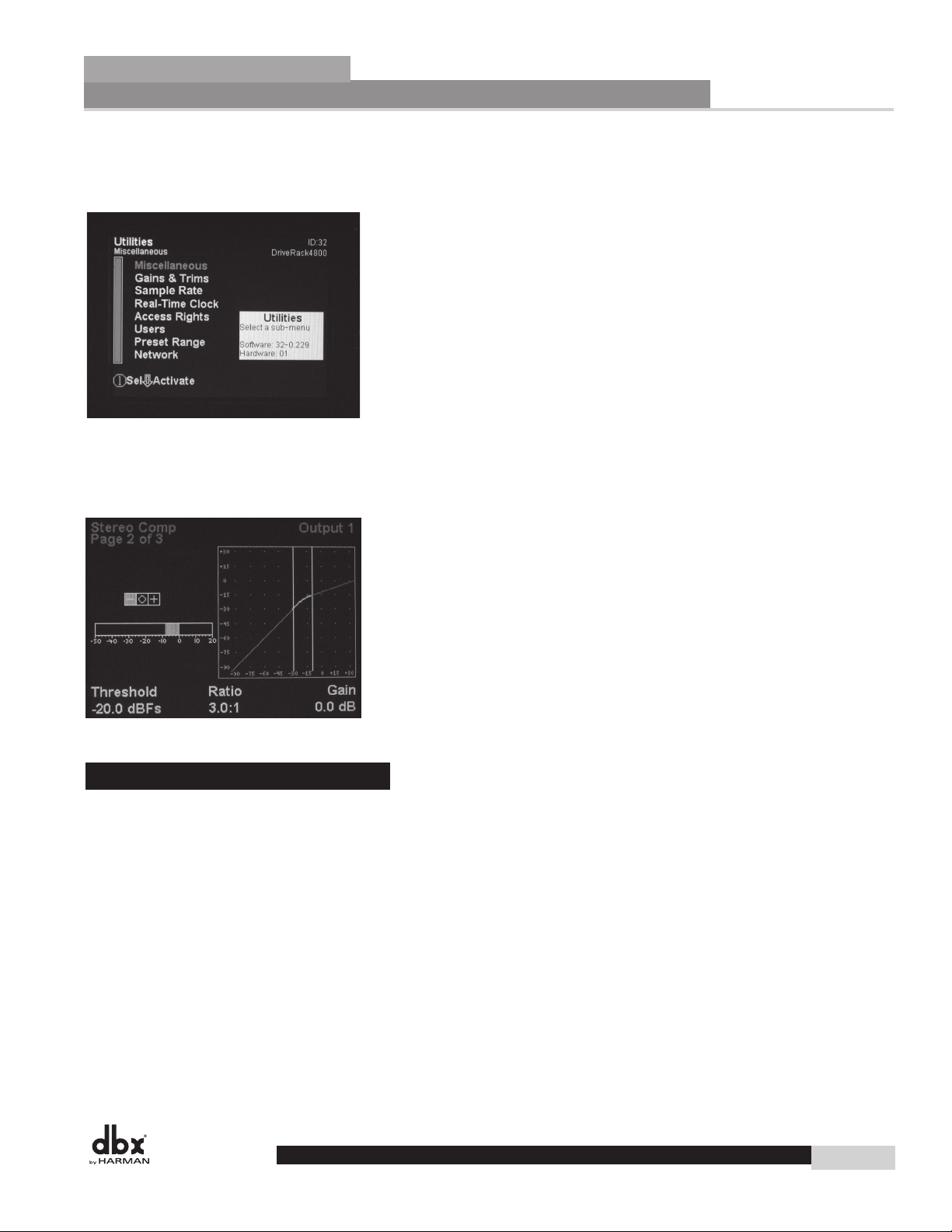
Utility Menu - Many of the global attributes of the DriveRack 4800 are located in the Utility menus,
including Sample Rate, Analog I/O Gain Structure, etc.
1. While in Edit mode press the UTILITY/METER button.
DriveRack
16
2. Scroll through the various Utility menus using Encoder Knob #1. Press the knob to enter the desired
menu.
3. Once in a Utility menu, use the PREV and NEXT buttons to navigate through the pages within that
menu.
4. To exit the Utility menus and return to Edit mode, press the PRESET button.
Meter Menu - The Meter menu provides you with additional high resolution meters for all the dynamics
functions of the DriveRack 4800.
1. While in Edit mode press and hold the UTILITY/METER button.
DriveRack® 4800/4820 User Manual
Page 27
®
Front Panel Operation
DriveRack
2. Use the PREV and NEXT buttons to navigate through the pages of meters.
3. To exit Meter menus and return to Edit mode, press the PRESET button.
Wizard Mode - The Wizard mode will provide you with setup functions. The Wizard mode is not functional in v1.00.
1. While in Edit mode press the WIZARD/CONFIG button.
Section 3
2. Use the PREV and NEXT buttons to navigate through the Wizard pages.
3. To exit the Wizard and return to Edit mode without making any changes, press the PRESET button.
Configuration Mode - The DriveRack 4800 is configurable from the front panel through the Configuration
mode. This mode lets you create a signal path and a combination of processing functions.
1. While in Edit mode press and hold the WIZARD/CONFIG button for two seconds.
2. Use the CHANNEL and FUNCTION buttons to navigate around the processing matrix.
3. In positions where a change of processing is possible, turning the Encoder #1 knob will accomplish this
change.
4. To link adjacent like functions, turn Encoder #3 knob.
DriveRack® 4800/4820 User Manual
17
Page 28

Section 3
®
Front Panel Operation
5. Once the desired configuration is created, press and hold the RTA/LOAD button to load the configuration.
6. To exit Configuration and return to Edit mode without making any changes to the configuration, press
the PRESET button.
DriveRack
18
DriveRack® 4800/4820 User ManualDriveRack® 4800/4820 User Manual
Page 29
®
DriveRack
Section 4
Software Operation
MODULE VIEW
DEVICE VIEW
VENUE VIEW
Page 30

Section 4
®
Software Operation
DriveRack
4.1 - DriveRack Philosophy
The most basic storage elements of the DriveRack 4800 and 4820 are the Attribute and the Preset.
Attributes are global parameters for that unit, while Presets are snapshots of the current processing functions
or modules, their location in the signal path, and their parameters (see Section 2.1 for more information
about Attributes and Presets).
4.2 - System Architect DriveRack 4800/4820 File Storage
System Architect provides you with the ability to store Presets in the DriveRack unit by using the Preset
Tool in the Device View Window (see next page). Attributes can be directly manipulated in the GUI as
well; most Attributes reside in the Utility menus.
System Architect can also save several file types in the computer including the Preset File, the Device File,
and the Venue File. A Preset File is a copy of the Preset information, all the processing function parameters
and their configuration. Saving a Preset File in the computer allows you to then transfer preset information to other users or create an archive of presets used for various occasions. A Device File is a copy of all
the Presets in the DriveRack device along with all the Attributes of that device. You can “clone” a unit by
saving a Device File from one unit and then opening that file in another unit. A Venue File is a snapshot
of the entire venue including all the units within the venue, their current Preset and their Attributes. The
Preset and Device files can be saved from the Device View Window (see below), and the Venue File can be
saved from the Venue View Window (see below).
4.3 - System Architect DriveRack 4800/4820 Philosophy
The philosophy of the HPro System Architect software is built around the idea of Views or Windows (used
interchangeably). Nearly every function of the DriveRack 4800 and/or 4820 can be accessed from one
of three windows: the Venue View, the Device Window, and the Module Window. These views all have
some common features including the standard Microsoft Windows Minimize and Close icons in the upper
right hand corner.
System Architect also provides a “Recycle” icon that is used to either recycle the window or spawn new
windows. If the Recycle icon is white, every new window that is opened will open in the same location and
take the place of the previous. If the Recycle icon is red, every new view that is opened will be in addition to
the others that are still on the screen. Clicking on the icon changes it from white to red. Window recycling
allows you to keep your screen manageable by automatically replacing windows instead of constantly opening up new windows. Recycling works for module views, device windows, and custom control panels. For
more information on window recycling see the Help File in System Architect. Additionally, right-clicking
on the Device View and the Module Window will bring up the “Right-Click” Menu that also includes
the standard Microsoft Move, Minimize, and Close, as well as provide a way to Dock the Window in the
Venue View or open the Help File.
4.3.1 - Module View
The Module Window (shown at the top of the next page) provides a view of the processing module and
all its parameters. The Module Window is accessed by double-clicking the processing icons in the Device
View. These icons are designed to look like the processing function they represent; for example, a Graphic
EQ icon looks like this:
20
DriveRack® 4800/4820 User Manual
Page 31

®
Software Operation
DriveRack
Module View Features
While changes to the parameters within the module are instantaneous, every Module View includes the OK
and Cancel buttons to either accept or reject these changes before closing the window. The Module View
also provides the Recycle Icon in the upper right hand corner, allowing the window location to be reused
upon opening a new module.
Section 4
4.3.2 - Device Window
The DriveRack Device View (seen below) is accessed by double-clicking the device icons in System
Architect’s Venue View, and provides access to the processing modules and other features of the DriveRack
4800 or 4820 devices. Like the processing icons, the device icons look like the devices they represent.
DriveRack® 4800/4820 User Manual
21
Page 32

Section 4
®
Software Operation
Device View Features
Besides access to the processing functions, the Device View offers many other features, some of which can
be found as pull-downs in the Windows Menu. Items in the Windows Menu include the File Menu, Edit
Menu, Tools Menu, View Menu, and Help Menu. Additional features of the Device View include the
Preset Tool, Meters, Mutes and Solos, and the RTA.
Device File Menu
The Device File Menu provides the ability to Open and Save Device and Preset Files to the computer as
well as Print Parameter Values.
DriveRack
Device Edit Menu
In the Device Edit Menu you can Copy and Paste processing module parameters as well as the Preset.
Device Tools Menu
In the Device Tools Menu you can access the Configuration Wizard, Zone Controller Wizard, Utilities,
and Manage Roles. The Configuration Wizard is central in the operation of the DriveRack 4800 because
it is through the Configuration Wizard that the DriveRack 4800 or 4820 is configured with the desired
signal path and processing elements. The Zone Controller Wizard is also important if you wish to use the
DriveRack 4800 or 4820 with ZC wall panel controllers. The Utility Menu holds several of the attributes
of the DriveRack 4800 including the Sample Rate, Analog I/O Gain Structure, Real Time Clock, the Preset
Range, and LCD Intensity. Manage Roles lets you select the access rights (View, Modify) that the four
System Architect roles will have for each processing function.
22
DriveRack® 4800/4820 User Manual
Page 33

®
®
Software Operation
DriveRack
DriveRack
Device View Menu
In the View Menu, you can select to Dock the window in the Venue View or leave it floating.
Device Help Menu
GUI Software Overview
Section 4
In the Help Menu, you can select from Contents, Index, or Search as ways to search for topics in the Help
File. There is also a link to the Device information; this can be helpful when troubleshooting with technical support because it gives a list of many of the attributes of the unit including Sample Rate, Critical
Error Count, IP address, etc. The Device Locate On/Off is a handy feature for finding devices in a larger
system. The Locate function flashes the front panel display. The About DriveRack menu item provides
more information about the unit as well as information about the DriveRack .dll driver in System Architect.
Preset Tool
The Preset Tool lets you store and recall Presets on the DriveRack device when online. It is important to
note that the Preset Tool is used to store Presets on the DriveRack Device while the File Menu/Save Preset
is used to save a Preset File on the computer.
DriveRack® 4800/4820 User Manual
23
Page 34

Section 4
®
Software Operation
Meters
The Meters in the lower left hand corner of the Device View are real time meters, and they show the current input and output levels if the unit is online. The meters can be turned off to reduce the amount of
network traffic if so desired.
Mutes and Solos
DriveRack
The Mutes and Solos are also in the bottom left hand corner of the Device Window, directly below the
Meters. Mutes provide a quick way of muting DriveRack 4800 outputs. The Solos employ the Mutes for
soloing of a single channel during setup.
RTA
Outside of the “normal” DriveRack 4800/4820 signal path, the RTA provides an additional utility that lets
you analyze incoming signals. Clicking on the RTA icon opens the RTA viewer.
24
DriveRack® 4800/4820 User Manual
Page 35

®
®
®
GUI Software Overview
Software Operation
DriveRack
DriveRack
DriveRack
4.3.3 - Venue View
GUI Software Overview
Section 4
Section 4
The Venue View is the most encompassing perspective, providing a “global” view of the entire venue or
system. The Venue View provides many features that make System Architect superior in the way that it
provides control of an audio system. Many of these features can be found as elements within pull-down
menus on the Windows Menu of the Venue View. Other features can be found by right-clicking on the
units within the Venue View. For more information about any of these features refer to the Help menu,
found on the Windows Menu of the Venue View.
Venue File Menu
Beginning with the File Menu, the Venue View lets you save and open Venue Files that are complete copies
of the entire system, including every single unit in the venue, their current presets and parameters, as well as
their attributes. Besides saving and opening Venue files, System Architect can also print a list of the devices
in the system and even the parameters within those units. If Manage Roles is set up, the File Menu can log
users out or switch users, providing varying amounts of control for these users.
DriveRack® 4800/4820 User Manual
25
Page 36

Section 4Section 4
®
GUI Software Overview
Software Operation
Venue Edit Menu
In the Edit menu, System Architect provides the ability to Undo or Redo commands as well as Cut, Copy,
Paste and Delete selected units in the Venue. The Find… command lets you find a specific unit in the
system either by name or ID#.
Venue View Menu
DriveRack
26
The View Menu (seen above) provides quick access to various menus, panels and toolbars.
The Device Panel lets you add various Harman Professional devices to the Venue.
System Explorer provides access to various parameters within each of the units in the venue.
The HiQnet Explorer shows all physical connections that are accessible to the system. If a HiQnet device
is available but is not currently part of the venue, it can be selected and dragged over into the venue view.
The Event Log shows system activity that has occurred within System Architect and on any HiQnet device,
including error messages. The log may be utilized by individual devices to perform certain operations. You
can also use the logs for troubleshooting.
The Controls Toolbox gives you the tools you need to construct a custom control panel.
Custom Control Panels are user-designed screens that can be totally customized to your specifications.
Custom Control Panels offer total versatility in designing and controlling a venue. They enable you to
manage venues more easily by simplifying common editing tasks and restricting access to audio systems by
other users.
DriveRack® 4800/4820 User Manual
Page 37

®
®
®
®
®
®
®
GUI Software Overview
GUI Software Overview
GUI Software Overview
GUI Software Overview
GUI Software Overview
Software Operation
DriveRack
DriveRack
DriveRack
DriveRack
DriveRack
DriveRack
DriveRack
Properties are all of the user-defined display options for any venue view, device, custom control panel, or
controls in System Architect. Different items provide different editable properties, such as changing the
name, background color, or background image.
The Navigator window gives you the ability to view the entire venue and locate a unit’s current position,
since not all units may be viewable in the current window.
Toolbars are also available from the View Menu including the Alignment toolbar, the Window Sets toolbar, and the Zoom toolbar. The Alignment toolbar provides tools that can be used in aligning the various
units in the venue view. The Windows Sets toolbar lets you have different device panels, control panels
and customer control panels available at the touch of a button, simplifying moving between these different
panels. The Zoom toolbar lets you zoom in or out in a venue.
Venue Insert Menu
GUI Software Overview
Section 4
Section 4
Section 4
Section 4
Section 4
Section 4
The Insert Menu provides the ability to insert devices into a venue.
DriveRack® 4800/4820 User Manual
27
Page 38

Section 4
®
Software Operation
Venue Panel Menu
The Panel Menu option lets you create and manage Custom Control Panels, with functions including add,
remove, import, export and activate a control panel.
Venue Tools Menu
DriveRack
28
The Tools Menu lets you manage and control the way System Architect functions.
Network Wizard locates all HiQnet devices physically connected to the network and
provides the ability to change their HiQnet and communications address.
Re-populate Venue automatically searches for devices and adds them to your venue.
Grouping Wizard creates a custom control panel with channels from multiple devices
linked together.
Venue Recall loads presets for multiple devices.
Event Log Archive displays a repository of old Event Log information.
Access Control allows the administrator to restrict or allow access to different parts of
System Architect for multiple users.
Options accesses settings related to the way System Architect functions and displays information.
DriveRack® 4800/4820 User Manual
Page 39

®
Software Operation
DriveRack
Venue Window Menu
The Window Menu manages the main Venue View window. It provides you with the following options:
New adds a new Venue View to the main window.
New Horizontal Group tiles the tab groups horizontally.
New Vertical Group tiles the tab groups vertically.
Section 4
Close Current closes the selected window tab.
Close All closes all window tabs except the primary Venue View.
Venue Help Menu
The Help Menu provides links to the Help File with different ways to find information; it also provides
information about System Architect and the various .dll files that are compiled within it.
DriveRack® 4800/4820 User Manual
29
Page 40

Section 4
Software Operation
®
DriveRack
30
DriveRack® 4800/4820 User Manual
Page 41

®
DriveRack
Section 5
In Use
FRONT PANEL
OPERATION
SOFTWARE
OPERATION
31
Page 42

Section 5
®
In Use
Under normal operation the most common modes are Configuration, Edit, Store and Recall Preset. The
simplest way to illustrate these modes in use is by example; this will be done for both the Front Panel
Navigation as well as the GUI.
In our example we’ll create a Stereo Tri-Amped System with a Mono Sub, a mono send to Delayed House
speakers, and Side Fill sends.
DriveRack
5.1 - Front Panel Operation
The example begins with recalling a preset from the Preset Table:
1. Press the PRESET/RECALL button to return to the main preset screen.
2. Press and hold the PRESET/RECALL button to enter Preset Recall mode.
3. Select Preset 8 Stereo 2-Way with Sub from the preset table by turning the Encoder #1 knob until Preset
8 appears on the display.
4. Press and hold the RTA/LOAD button to load the preset.
This 2x5 preset is a good starting point, but we want to make some modifications to it. We want to link
the Input Graphic EQs and change the Inserts on the main stereo feed from Notch Filters to Compressors.
We also want to rename the Inputs, put a Mixer in the Mid position, and lengthen the Delay that feeds
Output 6, our Delayed speaker send. To do all this we must make a Configuration change.
To make a Configuration change:
1. Since the preset was just recalled, we’re already in Edit Preset mode and can press and hold the
WIZARD/CONFIG button for two seconds to enter Configuration mode.
32
DriveRack® 4800/4820 User Manual
Page 43

®
In Use
DriveRack
2. Press the INPUT A button and the EQ 1 button to move to the Input Graphic EQ.
Section 5
3. Turn Encoder knob #3 to link the Graphic EQs on Inputs 1 and 2.
4. Press the INSERT 2 button and turn the Encoder #1 knob to select the Compressor.
5. Turn Encoder knob #3 to link the Compressors on Inputs 1 and 2.
6. Select the Input Router on Input A by pressing the MIX/ROUTE button and INPUT A button.
DriveRack® 4800/4820 User Manual
33
Page 44

Section 5
®
In Use
7. Rename the Input by pressing Encoder #2 and using Encoder #1 and Encoder #2 to select characters
and advance the cursor.
8. Store the name by pressing the STORE/DELETE button.
9. To change the Mid Router to a Mixer, press the Output 6 button and then the MIX/ROUTE button,
then turn Encoder #1 to select Mixer.
10. While on Output 6, press the DELAY button to allocate enough Delay for these speakers.
11. Load this configuration by pressing the RTA/LOAD button, and one more time to confirm this
configuration change. You’re returned to Edit mode and the main preset screen.
DriveRack
Once the configuration loads, the change is now active and audio can be passed through this new configuration. Now we’ll edit the processing function parameters in the Bandpass filter, Compressor and Graphic
EQ, and create the correct mono mix for our Delayed speakers. To do this we take the following steps:
1. Press the OUTPUT CHANNEL 1 button and the BANDPASS button to navigate to the Bandpass
filter on Output 1.
2. Edit the parameters found on page 1 of that menu (Lowpass Filter Frequency and Slope). The name of
the output that is being edited is shown in the upper right corner; the total number of pages is shown
in the upper left corner.
3. Press NEXT to access the next page of parameters. Continue until all desired pages of parameters have
been edited.
34
DriveRack® 4800/4820 User Manual
Page 45

®
In Use
DriveRack
With three pages per Bandpass filter set, it should be noted that there will be nine total pages in this
function; these pages can either be accessed by continuing to press NEXT PAGE or by pressing the next
OUTPUT CHANNEL button. Since in a 2x5 Bandpass the first two and the next two outputs are
“linked” together, both outputs 1 and 2 will be controlled together in the first three pages of the Bandpass.
Likewise, outputs 3 and 4 will be linked together, and controlled in pages 4 through 6. Output 5 is the
mono summed output designed to be the Subwoofer output, and it is controlled on pages 7 through 9.
4. Navigate to the linked Graphic EQ module on Inputs 1 and 2 by pressing the INPUT CHANNEL A
button and the EQ 1 button.
Section 5
5. Edit the Graphic EQ parameters using the NEXT and PREV buttons to move between the pages. Once
again, Input Channels A and B are linked so adjusting one actually adjusts them both.
6. Since the we’re already in the Input Channel A Graphic EQ, moving to the Stereo linked Compressor
on these same channels requires just a single button press on the INSERT 2 button.
7. Use the NEXT and/or PREV PAGE buttons to navigate to the various desired parameters.
8. Press the OUTPUT CHANNEL 6 button and the MIX/ROUTE button to move to the Output Mixer
on Output 6.
9. Make the changes by finding the Input channels A and B and adjusting their relative amounts using the
Encoders.
10. Press the PRESET/RECALL button to return to the main preset screen.
DriveRack® 4800/4820 User Manual
35
Page 46

Section 5
In Use
Now that the preset has had its configuration changed and has been edited, we can Store it:
1. Press the STORE/DELETE button to enter Store mode.
DriveRack
®
2. Select a location for this new preset in the preset table by turning Encoder Knob #1. (A preset can either
be stored over an existing preset or stored in an empty location.)
3. To name the preset, press Encoder Knob #2, then use the Encoder Knobs #1 and #2 to change the character and move the cursor through the name. (To accept the name change press the STORE/DELETE
button; to reject the name change press Encoder Knob #3.)
4. Once the name and location have been selected, press the STORE/DELETE button to store the preset,
and again to confirm storing the preset.
5. If you want to store an altered preset over the previous preset in the same location, you can press the
STORE/DELETE button three times in succession.
6. Once the preset is stored, you’re returned to the main preset screen and Edit mode.
5.2 - GUI Operation
The example begins with recalling a preset from the Preset Table:
1. Open the Device Window by double clicking on the DriveRack 4800 or 4820 icon in System architect.
2. Click the RECALL button on the Preset Tool. The Preset Recall dialog appears, where you can select a
preset and View it, Recall it, or Cancel the Recall operation.
3. Select Preset 8 Stereo 2-Way with Sub from the list and click on the Recall button.
As before, this 2x5 preset is a good starting point, but we still need to make a Configuration change. To
change the configuration, do the following:
1. Click on the Tools menu in the DriveRack Device window.
36
DriveRack® 4800/4820 User Manual
Page 47

®
In Use
DriveRack
2. Select the Configuration Wizard.
3. Use the links on the left side of the page to quickly jump to the desired locations.
4. Select the EQs link in the Input Section, and click the check box to link the Input Channel A and B
Graphic EQs.
5. Select the DSP Inserts and Delay link in the Input Section, and in Insert 2 on Channels A and B select
Compressor from the pull down menu. Now check the link button that is between them and to the
right.
6. To select between output Mixers and Routers, select the Output Mixers and router link. Use the Radio
buttons to select a Mixer on Output 6.
7. If you forget to rename the Inputs, you can quickly jump back to the Input Channels (by selecting the
Input Channels link) and rename the inputs there.
8. The final Configuration change is allocating Output Delay. Click on the PEQ and Delay link for the
Output Section and select the desired Delay length from the pull down menu in the Delays. Notice
that the GUI keeps a running total of the allocated Delay and provides a warning when the maximum
Delay has been exceeded.
9. Once all the configuration changes have been made, click the Finish button at the bottom of the page.
Now that our configuration is complete, we can Edit the parameters in the Bandpass filter, Compressor and
Graphic EQ, as well as create the correct mono mix for our Delayed speakers:
Section 5
1. Double click the linked Input Graphic EQ icon. The Graphic EQ function opens.
2. Select the frequency faders and adjust them to the desired location. If you make a mistake, you can select
the Flat or Restore button. The Cancel button at the bottom of the editor also can be used to cancel
any changes; the OK button accepts any changes that were made.
3. Double click on the stereo linked Compressor icon to open the Compressor editor and provide access
to all the Compressor parameters.
4. Double click the 2x5 Bandpass icon to open the Bandpass/Crossover filters and allow access to those
parameters.
5. Double click the Output Mixer on Output Channel 6 to open the Mixer and provide access to those
parameters.
The final operation we want to perform is to Store this as a preset in the DriveRack unit. Note that in the
GUI you can also save this as a preset or device file to the Computer. To store the preset:
1. Click on the Store button on the Preset Tool. The Store dialog opens.
2. Select the location in the Preset Table where you want to store the preset.
3. Select the preset’s name.
4. Click the Store button to store the preset.
DriveRack® 4800/4820 User Manual
37
Page 48

Section 5
In Use
®
DriveRack
38
DriveRack® 4800/4820 User Manual
Page 49

®
DriveRack
Section 6
Detailed Parameters
DETAILED
PARAMETERS
Page 50

Section 6
®
Detailed Parameters
The DriveRack 4800 and 4820 provide a wealth of processing capabilities. This processing can be broken
into two distinct sections: Input Processing and Output Processing. Both the Input and Output sections
offer two types of processing functions, Fixed and Insert. Fixed processing modules can be linked and/or
switched with a similar type of function, but they are fixed in their location in the DSP path. An example
of a Fixed processing function is the Input Graphic EQ or EQ1. The Input Graphic EQ can be linked
between adjacent channels. Insert processing functions have fixed locations in the DSP chain, but they
differ from Fixed processing functions because there are several different types of processing that can be put
into these locations. An example of Insert Processing is the second Output Insert. This Insert gives you a
selection of Compressor, Limiter, Noise Gate, or Automatic Gain Control. Like the Fixed functions, they
too can be linked between adjacent channels if there is the same type of function in the other channels.
The following section outlines each of the Fixed processing functions available in both the Input and
Output sections (Sections 6.1-6.10). Following the Input and Output Fixed functions, the Insert
Processing functions is also outlined (Sections 6.11-6.19). These outlines provide GUI images for each of
these functions and describe the various parameters associated with each function.
DriveRack
6.1 - Input Mixer
Each input DSP channel can be configured with either an Input Mixer or Router. The Input Mixer lets
you mix between the input signals. Master Gain is also available, along with Pink Noise On/Off and Pink
Noise Gain.
40
Analog, AES/EBU, and CobraNet faders
Provides gain control for each of the input sources (–inf to +20dB).
Pink Noise Gain fader
Provides Gain control of the internal Pink Noise source (-20 to +20 dB).
Pink Noise On/Off switch
Turns the pink noise on or off.
Master Gain fader
Provides Gain control for the Mixer module (–inf to +20dB).
DriveRack® 4800/4820 User Manual
Page 51

DriveRack
®
Detailed Parameters
Section 6
6.2 - Input Router
The Input Router lets you select from any of the input sources and adjust the Master Gain. Pink Noise
On/Off and Gain are also available in this module.
Selected Source Switch
Allows selection between the input Sources (Analog 1-4, AES/EBU 1-4, CobraNet 1-4).
Pink Noise Gain fader
Provides Gain control of the internal Pink Noise source (-20 to +20 dB).
Pink Noise On/Off switch
Turns the pink noise on or off
Master Gain fader
Provides Gain control for the Router module (–inf to +20dB).
DriveRack® 4800/4820 User Manual
41
Page 52

Section 6
Detailed Parameters
®
DriveRack
6.3 - Input Graphic EQ
The DriveRack 4800/4820 provides a 31 band Graphic EQ on each input channel. This EQ offers up to
+/-15dB of gain at each of the 31 ISO frequency centers.
EQ On/Off switch
This turns the Graphic EQ on and off.
Flat/Restore switch
This either flattens the EQ or restores it to its previous settings.
Frequency switch
This lets you select any one the 31 frequencies and is adjustable between 20Hz to 20kHz on ISO frequency
centers.
Gain fader
This lets you cut or boost the selected frequency by up to 15dB.
42
DriveRack® 4800/4820 User Manual
Page 53

®
DriveRack
Detailed Parameters
6.4 - Input 9-Band Parametric EQ
The DriveRack 4800 and 4820 offer a second EQ (EQ2), after the input Graphic EQ, that can be configured as either a Graphic or 9-Band Parametric EQ. The 9-Band Parametric EQ provides Frequency, Gain
and Q control for each EQ band.
Section 6
EQ On/Off switch
This turns the Parametric EQ on and off.
Flat/Restore switch
These buttons either flatten all bands (Flat) or restore (Restore) all bands to their previous settings.
Type Bell and Shelf switch
Filter 1 and 9 are selectable between Bell and Shelf.
Filter Select switch
This allows selection of the Parametric EQ filter to be adjusted.
Filter On/Off switch
This turns the Selected (1-9) parametric EQ on and off.
Frequency (Fc) fader
This sets the frequency of the selected Parametric EQ and is adjustable between 20Hz to 20kHz.
Gain fader
This sets the amount of boost or cut of the selected Parametric EQ, and is adjustable between +/-15 dB.
Q fader
This sets the Q (or bandwidth) of the selected Parametric EQ and is adjustable between 0.13 to 16.0.
DriveRack® 4800/4820 User Manual
43
Page 54

Section 6
Detailed Parameters
6.5 - Input Delay
Each input channel of the DriveRack 4800 and 4820 provide up to 680 mSec of Input Delay.
DriveRack
®
Delay On/Off switch
This turns the input channel Delay module on and off.
Delay fader
This sets the amount of delay time and is adjustable in either 10 or 20 µSec steps (one sample at either 96
or 48 kHz). The Input Delay maximum is 680 mSec.
Units switch
This selects what the Delay is expressed in, Seconds, Feet or Meters. The GUI shows all three simultaneously.
44
DriveRack® 4800/4820 User Manual
Page 55

®
DriveRack
6.6 - Output Mixer
Each output DSP channel can be configured with either a Mixer or Router. The Output Mixer lets you
mix between signals coming from the input DSP channels. Master Gain and Muting of this Mixer is also
available.
Detailed Parameters
Section 6
Channels A-D
Provides gain control for each of the input channels (–inf to +20dB).
Master Gain fader
Provides Gain control for the Mixer module (–inf to +20dB).
Master Mute switch
Allows output muting of the Mixer module.
DriveRack® 4800/4820 User Manual
45
Page 56

Section 6
®
Detailed Parameters
6.7 - Output Router
The Output Router lets you select from any of the input channels, adjust the Master Gain and Mute the
output.
DriveRack
Selected Source Switch
Allows selection between the input channels (Channels A-D).
Master Gain fader
Provides Gain control for the Router module (–inf to +20dB).
Master Mute switch
Provides Mute control for the Router module.
46
DriveRack® 4800/4820 User Manual
Page 57

DriveRack
®
Detailed Parameters
Section 6
6.8 - Output Bandpass Filter/Crossover
The DriveRack 4800/4820 provides a Bandpass Filter on each output channel. These filters can be configured as Crossovers so you can adjust the frequency content of the adjacent output channels.
Band Select switch
This selects the specific band or channel to be adjusted.
Highpass (HiPass) fader
This adjusts the lowest frequency that the output channel will be able to achieve. The range of this control
is between “Out” to 20kHz, where “Out” denotes that the filter is not in the signal path and is not active.
Lowpass (LoPass) fader
This adjusts the highest frequency that the output channel will be able to achieve. The range of this control
is between 20 Hz and “Out”, where “Out” denotes that the filter is not in the signal path and is not active.
Gain fader
This sets the gain of the Crossover output and is adjustable between -Inf and 20dB.
Lowpass and Highpass Slope switch
This selects the desired slope and filter topology. It offers the following filter topologies and slopes:
Bessel 6, 12, 18, 24, 36, 48 dB/Octave
Butterworth 6, 12, 18, 24, 36, 48 dB/Octave
Likwitz-Riley 12, 24, 36, 48 dB/Octave
Polarity switch
This switches between Positive (+) and Negative (-) Polarity.
Phase switch
This switch makes the Phase adjustment available on the GUI; it is only available on the GUI.
Phase fader
This fader allows adjustment of the Phase in 5 degree steps and can be adjusted from 0 to -175 degrees.
Show Composite button
Only available on the GUI, this button provides a composite view of the Output Parametric and Bandpass
filtering on the channel. If Window Recycling is turned on it is a convenient way to “jump” back and forth
between the Composite and filter views (Bandpass and Parametric) while making changes.
DriveRack® 4800/4820 User Manual
47
Page 58

Section 6
®
Detailed Parameters
DriveRack
6.9 - Output 6-Band Parametric EQ
The DriveRack 4800 and 4820 offer an Output 6-Band Parametric EQ on each output channel. The
6-Band Parametric EQ provides Frequency, Gain and Q control for each of the 6 EQ bands.
EQ On/Off switch
This turns the Parametric EQ on and off.
Flat/Restore switch
These buttons either flatten all bands (Flat) or restore (Restore) all bands to their previous settings.
Show Composite button
Only available on the GUI, this button provides a composite view of the Parametric and Bandpass filtering
on the channel. If Window Recycling is turned on it is a convenient way to “jump” back and forth between
the Composite and filter views (Bandpass and Parametric) while making changes.
Filter Select switch
This allows selection of the Parametric EQ filter to be adjusted.
Filter On/Off switch
This turns the Selected (1-9) parametric EQ on and off.
Frequency (Fc) fader
This sets the frequency of the selected Parametric EQ and is adjustable between 20Hz to 20kHz.
Gain fader
This sets the amount of boost or cut of the selected Parametric EQ, and is adjustable between +/-15 dB.
48
Q fader
This sets the Q (or bandwidth) of the selected Parametric EQ and is adjustable between 0.13 to 16.0.
Type Bell and Shelf switch
Filter 1 and 6 can be switched between Bell and Shelf filters.
DriveRack® 4800/4820 User Manual
Page 59

®
DriveRack
Detailed Parameters
6.10 - Output Delay
The output channels of the DriveRack 4800 and 4820 provide up to 1360 mSec of configurable Delay,
this means that the Delay can be allocated to where it is needed.
Delay On/Off switch
This turns the output channel Delay module on and off.
Section 6
Delay fader
This sets the amount of delay time and is adjustable in either 10 or 20 µSec steps (one sample at either 96
or 48 kHz).
Units switch
This selects what the Delay is expressed in, Seconds, Feet or Meters. The GUI shows all three simultaneously.
DriveRack® 4800/4820 User Manual
49
Page 60

Section 6
®
Detailed Parameters
DriveRack
6.11 - Advanced Feedback Suppression (AFS®) Insert
The DriveRack 4800/4820 offers the exclusive dbx Advanced Feedback Suppression (AFS) feedback
elimination module as an Insert processing function on the Input channels. This feedback suppression
algorithm reduces feedback by first finding the location of a feedback frequency and then placing a very
sharp notch filter at the exact frequency that is feeding back. Because the AFS algorithm can find the exact
frequency down to 1/100th of a Hertz, the notch filter used can be extremely sharp, in most cases 1/80th
of an octave. These sharp notch filters are so narrow that in most cases they cannot be heard, so the sonic
integrity of the system remains intact. With the AFS algorithm active, the unit removes only the feedback
frequencies without affecting the remaining audio spectrum.
AFS On/Off switch
This turns the AFS function on or off.
Clear Live and Clear All buttons
These buttons (when selected) reset the feedback filters. If Clear Live is selected, only the live filters are
reset. If Clear All is selected, then all of the filters are reset.
Mode switch
The Mode switch toggles between Fixed and Live mode. Fixed mode sets Fixed filters and Live mode sets
Live filters. Fixed filters will remain in place until they are reset. Live filters will either remain until they
are needed for another feedback frequency, or they will “Lift” (if Live filter Lift is engaged). Fixed mode is
used for setting up the algorithm; in fixed mode the algorithm is more sensitive to system resonances and
Fixed (or locked) filters are set. The best way to set Fixed filters is to open all the system microphones and
without any signal source present slowly raise the system gain. As resonances are reinforced the algorithm
will lock onto those frequencies and set Fixed filters. Once all the Fixed filters are set, the unit can be placed
into Live mode. In Live mode the filters are also set when a resonance is recognized. However, in Live
mode this filter can be moved to another frequency if it is needed in that location. Live filters also have the
capability of “Lifting”, which means that each Live filter can have a timer associated with that filter. Once
the timer elapses, the algorithm will check to see if the filter is still needed. If it is needed, the filter remains.
If it is no longer needed, the filter is removed and is then ready to be placed elsewhere.
50
DriveRack® 4800/4820 User Manual
Page 61

®
DriveRack
Detailed Parameters
Type switch
The Type switch toggles the AFS function between different sensitivities and filter Q settings corresponding
to the type of application. The different Types are Speech (Highest Sensitivity, Bandwidth = 1/5 octave and
Q=7.25), Music Low (High Sensitivity, Bandwidth = 1/10 octave and Q=14.5), Music Medium (Medium
Sensitivity, Bandwidth = 1/20 octave and Q=29), and Music High (Lowest Sensitivity, Bandwidth = 1/80
octave and Q=116).
Detector Highpass fader
This parameter sets a Highpass filter in the path of the AFS detector. There may be occasions where the
AFS algorithm is removing too much low end because it is being triggered by Synthesizer or Bass notes that
are not really feedback. These waveforms can be tricky because the notes will not only appear to be feedback to the algorithm, they will also cause the filters to widen out because they appear like several feedback
frequencies closely located to each other. This Highpass parameter provides a mechanism to make the AFS
algorithm less sensitive to low frequencies (thereby setting fewer filters in the bass region) and is adjustable
between Off, 11.7 - 410.1Hz.
Sensitivity fader
The AFS algorithm is very effective when the audio has a nominal level of 0 dBu. However, if the audio is
too low in level the AFS algorithm may not catch feedback as quickly as possible. By increasing or decreasing the sensitivity you can adjust for audio that is either too loud or too soft and help the AFS function
properly. The Sensitivity fader can be adjusted between up to +/- 20dB.
Section 6
Live Filter Lift switch
This parameter turns the Live Filter Lift functionality on and off.
Lift After fader
In Live mode the AFS filters offer Live Filter Lift which can remove extraneous filters. This parameter sets
the timer length for the live filter lift. Once a filter’s timer has run out, the algorithm checks to see if the
filter is still necessary. This timer ranges from 5 seconds to 60 minutes.
Number Fixed fader
This parameter sets the number of Fixed AFS filters. This also sets the number of Live filters; the total
number of filters minus the number of Fixed Filters equals the number of Live Filters. The number of
Fixed filters can range between 0 and 12.
Total Filters fader
This parameter selects the total number of filters available and can range between 0 and 12.
DriveRack® 4800/4820 User Manual
51
Page 62

Section 6
Detailed Parameters
®
DriveRack
6.12 - Automatic Gain Control (AGC) Insert
The Automatic Gain Control Insert is available in the DriveRack 4800 and 4820 in both the Input and
Output Insert modules. Automatic Gain Control (or AGC) is used to keep the average level of a signal
constant. This is done by selecting a desired Target output level and the Window around that Target. The
AGC keeps the signal within the Window around the selected Target by slowly adjusting the gain. The
maximum gain that can be applied to the signal is selected by the Gain parameter. When the input signal
falls below the Threshold parameter, the AGC stops adding gain and returns to unity. This prevents the
AGC from adding gain when there is no signal present and raising the system noise floor. Within the AGC,
high level peak signals are reduced by a fast acting Limiter to prevent clipping and distortion. The AGC
Threshold meters show what region of the AGC the input signal is in. The T (yellow) indicates the signal
is within the Window. A red + indicates the signal is above the target window, and a green - indicates the
AGC is adding Gain and is at or below the window. When the Threshold meter is turned off, the signal
is below the Threshold. The Limiter also has a Threshold meter indicating when the signal has crossed the
Limiter Threshold.
52
AGC On/Off switch
This turns the AGC module On and Off.
Threshold fader
The Threshold sets a lower limit to the AGC. It prevents the AGC from adding gain below the Threshold
and raising the noise floor. The Threshold range is between -80 to -50dBFS.
Gain fader
This adjusts the maximum amount of Gain that can be added by the AGC, and ranges between 1 and
20dB.
Target fader
The Target parameter defines what you would like the average output level of the AGC to be. If the average
level of the signal rises above the Target the gain will be reduced. If the average level of the signal is below
the target Gain will be added. The Target range is between -40 and -1 dBFS.
DriveRack® 4800/4820 User Manual
Page 63

®
DriveRack
Window fader
This parameter adjusts the amount of variation in the output and ranges from 1 to 10dB. For most applications a Window of +/- 2 or 3 dB maintains the signal adequately.
Attack fader
The Attack fader adjusts how fast the AGC will increase gain after the signal drops below the Target. It
ranges from 1 to 9.95 Seconds.
Release fader
This parameter adjusts the AGC rate of gain reduction once the signal is above the Target. It ranges
between 10 to 0 dB/Second.
Limiter Threshold fader
The AGC is designed to add or remove gain slowly so that the overall response will sound natural. Because
of its slow nature, a fast Limiter has been added to the AGC to protect the system from sudden transients.
The Limiter threshold can be set from the top of the AGC Window up to 0dBFS.
Limiter Auto On/Off switch
This button turns Auto mode for the Limiter on and off. Auto mode dynamically sets the Limiter Attack
and Release based on the input signal.
Detailed Parameters
Section 6
Limiter Attack fader
This parameter sets the speed at which the limiter starts to reduce the gain of the input signal once it has
crossed the limiter threshold. It ranges from .01 to 200 mSec.
Limiter Release fader
The Limiter Release parameter sets the rate at which the Limiter will go out of gain reduction once the
signal drops below the threshold. The Release range is between 360 and 5 dB/Sec. Auto mode deactivates
this parameter.
DriveRack® 4800/4820 User Manual
53
Page 64

Section 6
®
Detailed Parameters
DriveRack
6.13 - AutoWarmth® Insert
The Fletcher-Munson Equal-Loudness curves show that the perception of low frequency signals decreases
quickly with decreasing volume. The DriveRack 4800 and 4820 offer the AutoWarmth® Insert module on
each output (Insert 1) to compensate for this perceived loss in low frequencies. AutoWarmth is a patent
pending process that compensates for the naturally occurring perceived loss of low frequency at low signal
levels. The result of using AutoWarmth is warm and balanced signal even at low signal levels.
AutoWarmth On/Off switch
This parameter turns the AutoWarmth function on and off.
Threshold fader
The Threshold sets the level at which AutoWarmth begins to work. Signals below the Threshold are processed to increase the Bass response in proportion to the overall volume of the signal. Above the Threshold
there is no processing. The Threshold meter will light green when the threshold has been crossed and
AutoWarmth is active. The Threshold range is between -60 and 0 dBFS. To set the Threshold, turn
AutoWarmth off and adjust the Master Gain to the desired listening level. Turn AutoWarmth on and
adjust the Threshold until the Threshold Meter is toggling on and off. Now as the volume decreases below
the Threshold, the bass will gradually increase. Be careful when using AutoWarmth followed by an AGC.
The AGC can add gain when the signal is below the AutoWarmth threshold resulting in overcompensated
Bass.
Amount fader
The Amount parameter controls how much bass is added. A setting of 1.00:1 compensates for the perceived loss of bass by inversely matching the Fletcher-Munson Equal Loudness curves. Higher settings
(greater that 1.00) cause more bass compensation; lower settings result is less bass compensation. The
Amount parameter is adjustable between 0.25:1 and 4.00:1.
54
DriveRack® 4800/4820 User Manual
Page 65

DriveRack
®
Detailed Parameters
Section 6
6.14 - Compressor Insert
The DriveRack 4800 and 4820 offer an Insert Compression function on both the Input and Output
Inserts. This function is modeled from classic dbx Compressors such as the 160 and the 165.
Compressor On/Off switch
This switch turns the Compressor module on and off.
OverEasy fader
OverEasy is a characteristic of dbx Compressors and is essentially a “soft-knee” function that occurs at about
the compression threshold. On analog dbx Compressors, OverEasy could only be turned on or off, but
in the digital domain this parameter can have a range. This parameter can be adjusted between 0 and 10
where 0 corresponds to no OverEasy, and 10 corresponds to a very wide soft-knee region. To match the
response of the classic dbx 160, an OverEasy of 6 is recommended.
Threshold fader
The Threshold is the signal level at which the unit begins to compress the signal. If the level is set to -10
dBFS, then any signal larger than -10 dBFS is compressed, and any signal that has a level that is lower
than -10dBFS is not. For most signals the most natural sound is achieved when most of the signal content
remains just below the Threshold and only the peaks cross the Threshold. The range of the Threshold
fader is -60 to 0dBFS.
Ratio fader
The Ratio is the rate at which the signal is reduced once the threshold is crossed. A 2:1 ratio means that
if the incoming signal is 2dB over the threshold, the unit will compress the signal, and output a signal that
only goes 1dB over the threshold. Setting the Ratio at Inf:1 makes the compressor act as a limiter. The
range of the Ratio parameter is from 1:1 to Inf:1.
Gain fader
This parameter, often called make-up gain, is used to compensate for the gain lost during compression. The
range of the make up gain parameter is -20 to +20dB.
DriveRack® 4800/4820 User Manual
55
Page 66

Section 6
®
Detailed Parameters
Auto On/Off switch
Auto mode dynamically sets the Attack, Hold, and Release parameters in real time, based on the incoming
signal. This switch turns the Auto mode on and off.
Attack fader
The Attack parameter sets how quickly the compressor starts to compress the signal after it passes the
threshold. The Attack can range between 0.1 mSec to 200 mSec. The Attack time is dynamically set while
in Auto mode.
Hold fader
The Hold parameter is the time the 4800/4820 remains in compression after the signal has dropped back
below the threshold. Hold is adjustable between 0 to 500 mSec and is dynamically set while in Auto mode.
Release fader
The Release parameter is the rate at which the Compressor comes out of compression once the signal is back
below the threshold and the Hold time has elapsed. Release is measured in dB per second. For example,
if Release is set to 5 dB/Sec, and the signal has 10dB of gain reduction, the release time is 2 Seconds. The
Release range is from 360 dB/Sec to 5 dB/Sec. The Release rate is dynamically set while in Auto mode.
DriveRack
56
DriveRack® 4800/4820 User Manual
Page 67

®
DriveRack
Detailed Parameters
6.15 - De-Esser Insert
The DriveRack 4800/4820 offers a De-Esser module available on the Input Inserts. This De-Esser effect
is ideal for removing unwanted vocal sibilance and is based on the original dbx 902 De-Esser module. A
De-Esser works by inserting a high frequency boost EQ filter in the detector path of a Compressor to “bias”
the compressor, so it compresses when there is a significant amount of high frequency content in the signal
passing through it. This De-Esser offers two modes: Highpass and Bandpass. Highpass mode functions
like most other De-Essers with a Highpass or shelving filter in the detector path. Bandpass offers the ability to remove sibilance within a certain band without being affected by other high frequency content. For
example, in Bandpass mode the Width can be set so the De-Esser will ignore frequencies above 12 kHz
while still removing unwanted sibilance in the neighborhood of 6 kHz.
Section 6
De-Esser On/Off switch
This turns the De-Esser on and off.
Frequency fader
This fader adjusts the center frequency the De-Esser uses when in Bandpass mode or the corner frequency
used when in Highpass mode. The frequency parameter is adjustable between 800 Hz to 8.00 kHz.
Amount fader
This parameter controls the amount of De-Essing. The amount control is a combination of the Threshold
and Ratio controls of a Compressor. Increasing the amount lowers the Threshold and increases the ratio
,thereby applying more De-Essing to the signal. The Amount is variable between 0 and 100%.
Type switch
This determines whether the De-Esser is in Highpass or Bandpass mode.
Width fader
The Width parameter sets the Q of the Bandpass Filter, and is adjustable between 16 and .25.
DriveRack® 4800/4820 User Manual
57
Page 68

Section 6
®
Detailed Parameters
DriveRack
6.16 - Noise Gate
The DriveRack 4800 and 4820 provide a Noise Gate Insert that can be placed in both the Input and/or the
Output section. A Noise Gate is used to remove unwanted low-level noise in a system. The basic premise
behind a Noise Gate is that gain reduction or Gating will be applied to the channel unless there is a signal
that is above some Threshold.
Gate On/Off switch
This turns the Gate on and off.
Threshold fader
This sets the Threshold level. If there is any signal above the Threshold, the Gate is Open, while a signal
that is lower than the Threshold is attenuated. Beware of setting the Threshold too high as it can cut off
the tail end of signals as they fade out (the sustain of a guitar note, a held piano chord, a reverb tail, etc.).
The Threshold is adjustable between -70 and 0 dBFS.
Ratio fader
This control determines how much the signal will be attenuated once it drops below the Threshold. This
ratio works opposite from that of the compressor or limiter. If a Ratio of 1:4 is selected, a signal that is
1dB below the threshold will be reduced in gain so that it becomes 4dB below the threshold. The Ratio is
adjustable between 1:1 and 1:15.
Max Attenuation fader
The Maximum attenuation sets the bottom limit for gain reduction that the Gate will apply. It is adjustable
between 0 to INF dB. 0 dB attenuation means that even though the Gate is “closed” there is no gain reduction. INF applies an infinite amount of gain reduction (in the digital domain this is done by multiplying
the signal by 0), resulting in no output.
Attack fader
The Attack parameter sets the speed at which the Gate opens once the Threshold has been crossed. It is
recommended that very fast attack times be used to catch the fronts of transient signals. The Attack parameter is adjustable between 0.1 to 200 mSec.
Hold fader
The Hold control sets the amount of time the gate is held open after the signal passes below the Threshold
point. It is adjustable between 0 to 500 mSec.
58
Release fader
The Release sets the rate at which the gate “closes” or attenuates once the end of the Hold time is reached.
Release can be adjusted between 360 and 5 dB/Sec.
DriveRack® 4800/4820 User Manual
Page 69

DriveRack
®
Detailed Parameters
Section 6
6.17 - Limiter Insert
The DriveRack 4800/4820 units offer a Limiter in the Output Insert position. A Limiter operates on the
same principles as a compressor (see section 6.14) but it is designed and used more for system protection
rather than musical dynamics control.
Limiter On/Off switch
This turns the Limiter module on and off.
OverEasy fader
OverEasy is a characteristic of dbx Compressor/Limiters is essentially a “soft-knee” function that occurs
about the threshold. On analog devices, OverEasy can only be turned on or off, but in the digital domain
this parameter can have a range. This parameter can be adjusted between 0 and 10 where 0 corresponds to
no OverEasy, and 10 correspond to a very wide soft-knee region.
Threshold fader
The Threshold is the signal level at which the unit begins to limit the signal. If the level is set to -10 dBFS,
then any signal larger than -10 dBFS is reduced in gain. The range of the Threshold fader is -60 to 0dBFS.
PeakStopPlus On/Off switch
This switch engages PeakStopPlus® and changes the Limiter from an RMS (Root Mean Squared) or averaging limiter to a peak limiter. The difference between these two types of limiters is in the signal that is
being fed to the detection circuit or algorithm. The detector of an RMS limiter is “looking” at an average
signal, while a peak limiter “looks” at the instantaneous signal. An averaging limiter will be less responsive
and will not actually limit every peak where a peak limiter will.
PeakStopPlus Overshoot fader
In the DriveRack when PeakStopPlus is engaged the algorithm allows selection of how much a transient
signal will be allowed to pass the limiter threshold before it is stopped. This amount is the Overshoot.
Overshoot can be adjusted between 2 and 6dB.
Auto On/Off switch
Auto mode dynamically sets the Attack, Hold, and Release parameters in real time based on the incoming
signal. This switch turns the Auto mode on and off.
DriveRack® 4800/4820 User Manual
59
Page 70

Section 6
®
Detailed Parameters
Attack fader
The Attack parameter sets how quickly the Limiter starts to reduce the gain of the signal after it passes the
Threshold. The Attack can range between 0.1 mSec and 200 mSec. The Attack time is dynamically set
while in Auto mode.
Hold fader
The Hold parameter is the time the 4800/4820 continues to reduce gain after the signal has dropped back
below the threshold. Hold is adjustable between 0 and 500 mSec and is dynamically set while in Auto
mode.
Release fader
The Release parameter is the rate at which the Limiter comes out of gain reduction once the signal is back
below the threshold and the Hold time has elapsed. Release is measured in dB per second. For example,
if Release is set to 5 dB/Sec, and the signal has 10dB of gain reduction, the release time is 2 Seconds. The
Release range is from 360 dB/Sec to 5 dB/Sec. The Release rate is dynamically set while in Auto mode.
DriveRack
60
DriveRack® 4800/4820 User Manual
Page 71

®
DriveRack
Detailed Parameters
6.18 - Notch Filter Insert
The 4800 and 4820 units offer 6-Band Notch Filter that can be inserted in the Input section. The Notch
filter is designed to provide a significant amount of cut in very narrow frequency bandwidths to remove
room resonances and other unwanted artifacts.
Section 6
Notch On/Off switch
This turns the Notch filter on and off.
Flat/Restore switch
These buttons either flatten all bands (Flat) or restore (Restore) all bands to their previous settings.
Filter Select switch
This selects the Parametric EQ filter to be adjusted.
Filter On/Off switch
This turns the Selected (1-9) parametric EQ on and off.
Frequency (Fc) fader
This sets the frequency of the selected Notch Filter, and is adjustable between 20Hz to 20kHz.
Gain fader
This sets the amount of boost or cut of the selected Notch Filter, and is adjustable between +6 and -36 dB.
Q fader
This sets the Q (or bandwidth) of the selected Notch Filter and is adjustable between 16 to 128.
DriveRack® 4800/4820 User Manual
61
Page 72

Section 6
®
Detailed Parameters
DriveRack
6.19 - SubHarmonic Synthesizer Insert
The SubHarmonic Synthesizer module is designed to provide additional low frequency content to audio
signals and is available as an Insert in both the Input and Output sections. It has been optimized to enhance
audio signals in a variety of professional applications, including nightclub and dance DJ mixing, theater
and film sound, music recording, live music performance and broadcasting. The SubHarmonic Synthesizer
offers two separate frequency bands of synthesis to provide the best combination of frequency content and
control.
SubHarmonic Synth On/Off switch
This turns the SubHarmonic Synth module on and off.
SubHarmonic Level fader
This parameter sets the overall level of the SubHarmonic Synthesizer and is adjustable between 0 and
100%.
24-36Hz Level fader
This controls the amount of bass synthesized within the 24 to 36 Hertz frequency band. This parameter
is adjustable between 0 and 100%.
36-56Hz Level fader
This controls the amount of bass synthesized within the 36 to 56 Hertz frequency band. This parameter
is adjustable between 0 and 100%.
62
DriveRack® 4800/4820 User Manual
Page 73

®
DriveRack
Section 7
Utilities
UTILITIES
Page 74

Section 7
®
Utilities
As stated earlier, the Utility menus contain many of the attributes of the DriveRack 4800 and 4820 devices.
With the exception of Access Rights (which are stored manually), these attributes are stored instantly as
they are changed. They are broken down into sub menus in both the GUI and on the unit. While these
sub menus are different in their arrangement, all the same attributes are available. In this section we will
follow the sub-menus in the order they appear in the DriveRack unit itself.
The Utilities menus in the DriveRack use Scroll Navigation, so an item can be selected from the menu by
scrolling down to it, then pressing the Encoder Knob to select that item. Pressing the UTILITY button
returns you to the main Utility menu.
DriveRack
7.1 - Miscellaneous
The first item on the menu when the UTILITY button is pressed is Miscellaneous. This contains the LCD
Intensity and Front Panel Lock. The LCD Intensity changes the brightness of the VGA display. Front
Panel Lock is a quick and easy way of locking out the entire front panel except for Mutes. To lock the
front panel from this Utility menu, turn Encoder Knob #3. To unlock the front panel, press and hold the
PRESET button for three seconds, and then press the Encoder Knobs in this order: #3, #2, #1.
7.2 - Gains & Trims
The Gains & Trims Menu has two pages. The first page contains the Analog Maximum Input and Output
Levels and the RTA Mic Pre Gain. The Analog Maximum Input and Output Levels let you adjust the
analog gain structure of the DriveRack 4800/4820. The values shown are the maximum input and output
levels in dBu that the DriveRack will support. These attributes let you maximize the gain structure of the
system by setting all the devices in the system so they clip at the same point. The DriveRack units come
from the factory with the maximum input and output levels set to +22dBu. The RTA Mic Pre Gain determines the amount of gain being supplied by the microphone preamp for the front panel RTA microphone
input.
The second page of the Gains & Trims menu contains the Trim Minimum and Maximum controls, which
let you set the maximum and minimum Trim amount available from the front panel. There is also a Trim
Reset that resets the Trims back to 0dB. The Trims can be set in increments of 3dB from 0 to +/- 12dB.
So you could have the Trims set up with a maximum amount of Trim boost of 3dB, but a maximum
amount of Trim cut at 12dB (Trim Minimum of -12dB). It should be mentioned that Trims are meant
to be used for situational corrections; they are not stored with a Preset. Trims Gain is done via DSP and
is pre-limited. They give the ability to quickly adjust gain without having to make changes to a Preset or
tuning. Trims are reset by either using the Trim Reset control in this Utility menu, or by recalling a Preset.
64
7.3 – Sample Rate
The Sample Rate menu has two pages and provides access to the clock source that the DriveRack 4800 and
4820 are using. The selections available within this menu include Internal 48 and 96kHz Clocks, AES/
EBU Channels 1,2 or 3,4, and External BNC Word Clock. Additionally the AES/EBU input channels
can be sample rate converted to follow some other clock source. All processing within the 4800 and 4820
occurs at the sample rate selected in this menu. The AES/EBU outputs of the DriveRack devices are also
clocked to this sample rate.
DriveRack® 4800/4820 User Manual
Page 75

®
DriveRack
Utilities
7.4 - Real Time Clock
The DriveRack 4800 and 4820 have an internal Real Time Clock. This clock allows the devices to load
a preset based on a time schedule, for automated system changes. The real time clock is set by syncing
the DriveRack device to a computer from which it extracts the clock information. The clock can also be
manually set in this Utility menu. Creating a list of Presets to be recalled automatically by the Real Time
Clock requires using the GUI and accessing the Schedule Wizard in the Tools menu.
7.5 - Access Rights
Access Rights are the security protocols that can provide or limit access and control to the device attributes,
functions, processing modules and/or their parameters. The DriveRack 4800 and 4820 have five “Roles”
of security clearance or Access Rights; the highest is the Administrator which always has full access to every
parameter and function. The other four Roles can be set up with varying access rights that are completely
Administrator definable. This Utility menu can be used to define the Roles. There are two pages to the
Access Rights menu. The first outlines user Roles in conjunction with the rights of various device processing parameters (EQ, Bandpass Filter, etc.), and the second page outlines user Roles pertaining to device
functions (Preset Recall, Edit Configuration, etc.). To define a Role, simply select the Role by turning the
Encoder #2 knob, then use a combination of Encoder Knobs #1 and #3 to select whether this Role has
access to the various functions of the 4800/4820. Once these Roles are defined, they can be assigned to
various users along with the password for that role. Access Rights for both Processing and Device Functions
must be stored by pressing the STORE button while in that Access Rights menu.
Section 7
Due to the possible complexity, users and their passwords must be set up using the System Architect software. It is important to note that System Architect allows individual users to be given Roles and individual
passwords. That way when you are no longer involved with the system it is relatively easy to remove the
user rather than change the Role password and update everyone with that Role.
7.6 - Users
The Users Utility menu provides the ability to select which Role the device is being used under. This menu
allows users of various Roles to log in with that Role’s password, giving them the access they need for their
application. Roles must be previously set up in System Architect before anyone can access the Users menu.
To log in, first select the Role by turning the Encoder Knob #1, and then push the knob to enter the password menu. Use the Encoder Knobs #1 and #2 to create the password and press the STORE button to
enter it. Pushing Encoder Knob #3 cancels and exits this page of the menu.
7.7 - Preset Range
The Preset Range Utility menu selects the range of Presets that are available to the user. Turning Encoder
Knobs #1 and #2 eliminates presets from the list that the user will be allowed to load.
7.8 - Network
In the Network Utility menu you can view and access the network settings, including:
MAC address – Hard coded from dbx, this cannot be changed.
IP address – This can be set via DHCP (see below), Auto IP, or manually.
Subnet Mask – This refers to a portion of a network.
Gateway – This refers to the path from one network to an alternate network.
DHCP – This is the acronym for Dynamic Host Control Protocol.
DriveRack® 4800/4820 User Manual
65
Page 76

Section 7
®
Utilities
Note: Setting up a basic Network
The DriveRack 4800 and 4820 come with an included Ethernet cable. The DriveRack 4800/4820 is set
up at the factory for DHCP allowing it to be assigned an IP address by a DHCP Server. If there is no
DHCP Server present, the DriveRack will then default to Auto-IP, meaning that it will give itself a semirandom IP address. For more information on how to properly configure the network setting please refer
to the Appendix.
DriveRack
66
DriveRack® 4800/4820 User Manual
Page 77

®
DriveRack
Appendix
Page 78

®
Appendix
DriveRack
A.1 - Specifications
Analog Inputs: (4)
Connectors: Female XLR
Type: Electronically balanced, RF filtered
Impedance: >50k ohms
Maximum Input Level: Software selectable for: +28, +26, +24, +22, +20, +18, +16, +14 dBu
CMRR: >40 dB typical, >55 dB at 1 kHz
Digital Inputs: (4) AES/EBU Channels
Connectors: Female XLR
Type: Transformer Isolated, RF filtered
Impedance: 110 ohms
RTA Input: (1) Analog
Connectors: Female XLR
Gain range: 20 dB to 50 dB in 10 dB increments
Analog Outputs: (8)
Connectors: Male XLR
Type: Electronically balanced, RF filtered
Impedance: 30 ohms
Max Output Level: Software selectable for: +24, +22, +20, +12, +8, +4 dBu
Digital Outputs: (8) AES/EBU Channels
Connectors: Male XLR
Type: Transformer Isolated, RF filtered
Impedance: 110 ohms
A/D Performance
Type: dbx Type IV™ Conversion System
Dynamic Range: 113 dB unweighted, 116 dB A-weighted
Type IV™ dynamic range: 126 dB with transient material, A-weighted, 22 kHz BW
123 dB with transient material, unweighted, 22 kHz BW
118 dB typical with program material, A-weighted, 22 kHz BW
Sample Rate: 48/96 kHz
A/D Wordlength: 24 bits
D/A Performance
Dynamic Range: 112 dB unweighted, 115 dB A-weighted
Sample Rate: 48/96 kHz
D/A Wordlength: 24 bits
System Performance
Dynamic Range: 110 dB unweighted, 113 dB A-weighted
Internal Processing: 32 bit floating point
THD + Noise: 0.004% typical at +4 dBu, 1 kHz, 0 dB input gain
Frequency Response: 20 Hz- 20 kHz, +/-0.25 dB, <10Hz - 50kHz +0/-3dB @ 96kHz
Interchannel Crosstalk: <-85 dB at 1 kHz, 0 dB input gain
Processing
Pre EQ Type: One 31-band Graphic EQ on each input One EQ that is switchable between
31-band and 9-band Parametric on each input
Range: +/- 15 dB
68
DriveRack® 4800/4820 User Manual
Page 79

®
DriveRack
Input Insert Processing: Two selectable Insert Processing blocks per input
Type: Noise Gate, Compressor, Auto Gain Control, De-Esser, Sub-Harmonic Synth, Advanced Feedback
Suppression
Input Delay Length: Up to 682 mSec available
Routing/Mixing: 4-input mixer available at each output allowing any input to be sent or mixed to any output
Output Insert Processing: Two selectable Insert Processing blocks per output
Type: Noise Gate, AutoWarmth
Advanced Feedback Suppression
X-Over Filter Configs: 1x1, 1x2, 1x3, 1x4, 1x5, 1x6, 1x7, 1x8, 2x2, 2x3, 2x4
2x5, 2x6, 2x7, 2x8, 3x3, 3x4, 3x6, 3x7, 4x4, 4x5, 4x8
Types: Bessel 6, 12, 18, and 24 dB per Octave
Butterworth 6, 12, 18, and 24 dB per Octave
Linkwitz-Riley 12, 24, 36, and 48 dB per Octave
Polarity: Positive and Negative
Phase Control: 0 to -180 degrees in 5 degree increments
Output Delay Length: 1365 mSec shared between the outputs
®
, Compressor, Auto Gain Control, Peak Limiter, Sub-Harmonic Synth,
Appendix
Miscellaneous:
I/O Transformers: Optional, Jensen® JT-11 and JT-123-dbx
CobraNet® I/O: Optional
Control: Ethernet, RS-232, Optional dbx ZC Wall Panels
Power Requirements: 100V to 240V 50/60Hz, 45 Watts
Dimensions: 3.5” x 19” x 12.15”
Weight: 11 lbs. (14 lbs. w/audio transformers)
Shipping Weight: 12.5 lbs. (15.5 lbs. w/audio transformers)
DriveRack® 4800/4820 User Manual
69
Page 80

®
Appendix
A.2 - Block Diagram
DriveRack
70
DriveRack® 4800/4820 User Manual
Page 81

p
p
g
p
y
p
p
y
®
DriveRack
A.3 - Preset Table
Appendix
ircseDemaNrebmuN teserP
noit
nepO ediW1
sbuS xuA /w HOF TS2
senoZ /w 4x3 RCL3
srotinoM yaW-24
yaw-4 UBE/SEA TS5
ylD /w rtslC yaW-26
yaW-2 TS7
buS /w yaW-2 TS8
yaW-3 TS9
buS /w yaW-3 TS01
dna
mA
.tu
tuo hcae
.elosnoc eht ffo deef xuA na morf srefoowbuS rof sretlif oerets
nideef
.refoowbuS
.refoowbuS
.refoowbuS onom a
.srotinom depma-ib ruof rof si teserp sihT
aw-4 oerets a sedivor
.revossorc
tuo refoowbus a htiw retsulc de
aled dna tu
.s
.AP depmA-iB oerets a rof si teserp sihT
.AP depmA-irT oerets a rof si teserp sihT
no sretlif ssapdnab tnednepedni gnidivorp nepo yletelpmoc si teserp sihT
fo tes lanoitidda na htiw revossorc pmA-iB oerets a sedivorp teserp sihT
tuptuo htruof a htiw metsys thgiR retneC tfeL a rof dengised si teserp sihT
UBE/SEA no elosnoc latigid a morf langis a tpecca ot dengised si teserp sihT
-iB a serutaef dna snoitacilppa ynam ni dradnats ylriaf si teserp metsys ehT
onom a rof tuptuo htfif a htiw AP depmA-iB oerets a rof si teserp sihT
onom a rof tuptuo htneves a htiw AP depmA-irT oerets a rof si teserp sihT
A.4 - Crossover Table
DriveRack® 4800/4820 User Manual
71
Page 82

®
Appendix
DriveRack
A.5 - Digital I/O and Clocking
A.6 - Word Clock Termination
Clock Source
75Ω
Coaxial
Cable
4800/4820
BNC “T”
75Ω BNC
Te rminator
4800/4820
4800/4820
72
DriveRack® 4800/4820 User Manual
Page 83

®
DriveRack
A.7 - Zone Controller Wiring and Installation
Zone Controller Wiring
All Zone Controllers can be wired serially or in parallel. To wire in series, each Zone Controller must have an
identification number (ID) chosen using the DIP switches on the side of the controller (see diagram A). Each
controller must have a unique number chosen although there may be multiple Zone Controllers controlling
a single zone, or a single Zone Controller that controls multiple outputs. The Zone Controllers can then be
wired together and connected to the DriveRack units (see diagram B).
To wire the Zone Controllers in parallel, a ZC-BOB must be used. Each Zone controller must have a unique
identification or number chosen using the DIP switches on the rear of the panel (see diagram A). To wire
in parallel, each controller must be wired into a port of the ZC-BOB with a connecting wire going to the
DriveRack units (see diagram C).
To set up the ZCs, the System Architect GUI must be used. Open the GUI and click on ZC Wizard in the
Tools menu. Select the type of ZC and the ID#. The ID numbers on the left side of the window correspond
to the identification number set using the DIP switches on the individual zone controllers. To select ID#2 for
example, simply flip the 2 switch into the on position. ID 1-6 are connected to top ZC input on the rear panel
and ID 7-12 are connected to the bottom input. To create ID 7-12, add 6 to the ID # selected on the back
of the ZC. For example, to get an ID# of 10, connect to the bottom ZC Input (7-12) and set the ID# to 4.
Appendix
Zone Controller Installation
The installation of the Zone Controllers MUST be accomplished with the use of cable which is rated VW-1
or higher. Common NEC designations which meet this rating include: CMP, CMR, CMG, CM and CMX.
ZC-1 - The ZC-1 is a programmable zone controller that allows volume level control from a wall panel.
ZC-2 - The ZC-2 is a programmable zone controller that allows volume level and mute control from a wall panel.
ZC-3 - The ZC-3 allows wall panel program selection for the DriveRack units.
ZC-4 - The ZC-4 provides contact closure program selection for room combining or fire safety applications
applications.
ZC-Fire - The ZC-Fire is the interface to generic fire alarm relays. When fire alarm activates, the general
purpose relay can typically be programmed to close if normally open or vices-versa. The ZC-fire interface
unit monitors the state of the relay (n.o. or n.c.) and upon the state of change, notifies the 4800/4820, which
then mutes its outputs.
ZC-6 - The ZC-6 is a push-button up and down volume controller.
ZC-8 - The ZC-8 is used for a combination of volume up/down, and four position source/program select.
ZC-9 - The ZC-9 allows wall panel program selection for the 4800/4820 units.
ZC-BOB - The ZC-BOB allows parallel or home run cabling of the Zone Controllers.
DriveRack® 4800/4820 User Manual
73
Page 84

®
Appendix
Diagram A
Diagram B
ID#1 ID#4
80-1342-A
UL-6500
IEC60065
.
RJ45
CONNECT ONLY TO
ZONE CONTROLLER
INPUT
80-1342-A
DriveRack
UL-6500
IEC60065
.
RJ45
CONNECT ONLY TO
ZONE CONTROLLERINPUT
74
Diagram C
DriveRack® 4800/4820 User Manual
Page 85

®
DriveRack
Cable Specification: EIA/TIA 568A Standard (pin to pin) 24 AWG wire
RJ-45
(8-Position)
1
2
3
4
5
6
7
8
White/Green
Green
White/Orange
Blue
White/Blue
Orange
White/Brown
Brown
RJ-45
(8-Position)
-VREF
1
2
3
4
5
6
7
8
Appendix
-Zone 1
-Zone 2
-Zone 3
-Zone 4
-Zone 5
-Zone 6
-GND
Diagram A
Diagram C
Diagram B
DriveRack® 4800/4820 User Manual
75
Page 86

®
Appendix
DriveRack
A.8 - ZC-4 Wiring Diagram
76
DriveRack® 4800/4820 User Manual
Page 87

®
DriveRack
A.9 - Factory Reset
Factory Reset Information
In the event that a reset is required, the DriveRack 4800/4820 offers you the option of performing a
“Hard” or “Soft” Factory Reset.
Power-Up Button Functions
All Power-Up Functions will use the MUTE 1 through MUTE 8 buttons. All Power-Up Functions
require a button(s) to be pressed and held as the unit power is turned on.
A. “Hard” Factory Reset
Press and Hold the <MUTE 2> button at power-up until the following message appears:
“! HARD RESET?”
“Yes <MUTE 7>”
“No <MUTE 8>”
Pressing the <MUTE 7> button will perform a System Reset, resetting all device Presets and Attributes.
Pressing <MUTE 8> will abort the Factory Reset sequence and the unit will reset normally.
B. “Soft” Factory Reset
Press and Hold the <MUTE 3> button at power-up until the following message appears:
“! SOFT RESET?”
“Yes <MUTE 7>”
“No <MUTE 8>”
Pressing the <MUTE 7> button will start a System Reset, resetting the device Attributes but maintaining
the User Presets.
Pressing the <MUTE 8> button will abort the System Reset sequence and the unit will reset normally.
Appendix
DriveRack® 4800/4820 User Manual
77
Page 88

®
Appendix
DriveRack
A.10 - Ethernet Networking
This section of the appendix provides a step-by-step guide on how to properly connect the DriveRack 4800
or 4820 to a Local Area Network (LAN) for several different network architectures. The first topology is a
simple direct connection using the provided Ethernet cable. The second method describes how to connect
several DriveRack units to create an isolated network using an Ethernet switch with DHCP and configure
them with the System Architect GUI. The following subsections explain how and when to connect to a
remote DriveRack using the proxy feature and some tips and examples of how to access your 4800/4820
by setting up a Virtual Private Network (VPN). This section of the appendix concludes with some further
networking considerations and troubleshooting tips that will help with connecting to your 4800/4820 unit
via Ethernet. If your application is more than these simple examples we recommend that you involve a
trained Ethernet network administrator in the design and commissioning of your system.
Careful planning needs be made before placing a 4800/4820 on a network that provides any access to
the public. Some examples of public access are direct access to the unit from the Internet, an unsecured
or weakly secured wireless network, a network jack in a public area that provides network access to the
4800/4820, or having a computer on the LAN that is not secured so that someone could use the System
Architect software to reconfigure the 4800/4820. It is highly recommended that the equipment be placed
on a protected, isolated network that does not have any connection to the public to prevent unauthorized
users from reconfiguring the unit. Please refer to the VPN portion of this section for more information.
Factory defaults for the Internet Protocol (IP) settings for the 4800/4820 are as follows:
IP Address: 169.254.2.2
Subnet Mask: 255.255.0.0
Gateway: 0.0.0.0
DHCP Support: Enabled
A.10.1 - Overview of TCP/IP Basics
IP address
An identifier for a computer or device on a TCP/IP network. Each device in a network has its own IP
address to identify it. Example: 126.126.17.42. Networks using the TCP/IP protocol route messages based
on the IP address of the destination. An IP address is made of four numbers separated by periods. Each
number can be zero to 255. The last number should not be a zero or 255. For example, 126.126.17.1 could
be an IP address. 126.126.17.0 would not be a valid IP address. A TCP/ IP or IP address has two parts:
the NETWORK ID and the HOST ID. The NETWORK ID identifies the network, and the HOST ID
identifies either the subnet and device, or just the device if there is no subnet. The subnet mask is a code
that indicates which part of the TCP/IP address is the NETWORK ID and which part is the HOST ID. In
subnet-mask code, 255 means “This part of the address is the NETWORK ID”. Example: Suppose the IP
ADDRESS of a device is 192.168.xx.yy and the SUBNET MASK is 255.255.x.y. That means, (192.168)
is the NETWORK ID. The remaining set of numbers (xx.yy) is the HOST ID. If your network stands
alone (it is not part of a larger network) then the HOST ID identifies each device in the network. If your
network is part of a venue’s larger network, your network is actually a sub-network or subnet.
Subnet
A small network within a larger network. For example, a TCP/IP network might be a subnet of a venue’s
network, which could include computers throughout the building, or a network might be divided into
subnets. For example, in a large installation, there may be one subnet per rack or room.
78
DriveRack® 4800/4820 User Manual
Page 89

®
DriveRack
DHCP (Dynamic Host Configuration Protocol)
This is a protocol for automatically assigning IP addresses to devices on a network. With dynamic (DHCP)
addressing, a device might have a different IP address every time it connects to the network. DHCP relies
on a DHCP server to assign and manage IP addresses.
A.10.2 - Connecting the Computer Directly
to the DriveRack
Assumptions:
• Using Microsoft Windows XP or 2000.
• Computer has a working Ethernet network adapter.
• You have administrative rights on the PC so that network settings can be changed if necessary.
1. Connect the included Ethernet cable to both the 4800/4820 and the PC.
2. Apply power to the 4800/4820 and wait for it to boot.
3. Open the HiQnet System Architect™ software.
4. The DriveRack device should at this point come up on the System Architect Venue View; it is connected
and can be controlled.
5. If it does not come up, you should first check that your System Architect GUI application has the
‘Network active when application starts’ and ‘Auto Populate venue view with detected devices’ boxes
checked; these are in the Tools menu under Options/General Network Information. If they are not
checked, click on them to select, then click the Ok button and relaunch System Architect.
Appendix
NOTE: Steps 6 and beyond should only be taken if the device cannot be found by the System Architect
software.
6. If Auto Populate is checked and the device is still not shown in the Venue View, it may be necessary to
select the Network Wizard in the Tools menu of the Venue View and change the IP address of the device
so it can be on the same network as your computer. Windows networking, in its default configuration,
will automatically configure your computer’s IP setting to something in the Auto-IP range (169.254.xxx.
yyy with a subnet mask of 255.255.x.y and no gateway).
7. Verify that you have the correct IP settings on your computer by running ipconfig.
a. This is done by clicking the Start button and selecting Run....
b. Enter cmd and press OK. This will bring up a command window (DOS box).
c. At the prompt, enter ipconfig and press Enter.
d. Now on your screen you will see your current IP settings. You should notice that the IP Address for
the adapter will be either 169.254.x.y (where x and y are numbers between 0 and 255), or 0.0.0.0.
If it is 0.0.0.0, wait for about a minute and enter the ipconfig command again. (Windows is still
trying to obtain an IP address.) It takes Windows about 1-2 minutes to set an Auto-IP address. If
you have some other address, you are either not hooked directly to the 4800/4820 with the Ethernet
cable, or your computer is configured with a static IP address.
8. Only perform these next steps if your computer is configured with a static IP address. (i.e. your IP address
is not 169.254.x.y or 0.0.0.0.) Otherwise skip to step 9.
a. From the PC Control Panel open the Network Connections window.
b. Right click on the Local Area Network (LAN) connection that is wired to the 4800/4820 and select
‘Properties’.
c. Highlight ‘Internet Protocol (TCP/IP)’ and then click the Properties button.
d. If ‘Use the following IP address’ radio button is selected, write down all the information on this page.
DriveRack® 4800/4820 User Manual
79
Page 90

®
Appendix
DriveRack
NOTE: The following steps will overwrite these settings, so you will need to keep this information to
restore your network settings.
e. Select the ‘Obtain an IP address automatically’ radio button.
f. (XP Only) Click on the Alternate Configuration tab and make sure that ‘Automatic private IP
address’ is selected.
g. Click OK in each window to close them.
h. After about 1-2 minutes your computer will configure itself with the correct IP settings. Verify this
by running the ipconfig command again, as described above.
9. Select the Network Wizard in the Tools menu of the Venue View and change the IP address of the device
so it can be on the same network as your computer. This is done by:
a. Selecting the device in the Network Wizard.
b. Click the Configure button.
c. Disable DHCP by deselecting that checkbox.
d. Type in the new IP address.
Once the DriveRack device and your computer are on the same network, the unit should show up on the
System Architect Venue View.
A.10.3 - Setup of a Simple Isolated
Ethernet Network Using DHCP
Assumptions:
• Using Microsoft Windows XP or 2000.
• Computer has a working Ethernet network adapter.
• You have an Ethernet switch/router with DHCP capability and Ethernet cables for each connection
needed.
• You have administrative rights on the PC so that network settings can be changed if needed.
• The Ethernet network consists of exactly one computer that will be used to run the System Architect
software and one or more 4800/4820 units.
1. Connect the PC and any 4800/4820 to the switch hub using normal Ethernet cables.
2. Apply power to all 4800/4820s and wait for them to boot.
3. With DHCP enabled, the Ethernet switch/router should assign an IP address to each of the devices
including your computer.
4. Launch System Architect. The DriveRack units should come up in the Venue View window.
5. If they do not, you should first check that your System Architect application has the ‘Network active
when application starts’ and ‘Auto Populate venue view with detected devices’ boxes checked; these are
in the Tools menu under Options/General Network Information.
6. If Auto Populate is checked and the network is active (this can be seen in the bottom left-hand corner
of the Venue View window) and the devices are still not shown in the Venue View, select the Network
Wizard in the Tools menu of the Venue View and change the IP address of the devices so they can be
on the same network as your computer.
A.10.4 - Proxy
Proxy is not available in version V1.0 of the DriveRack 4800/4820 firmware, but will be available in
upcoming releases. The proxy feature allows you to access a 4800/4820 over a complex or remote network.
An example of this is when the PC and the 4800/4820 reside on different subnets. The mechanism that is
used by default for the System Architect software to discover and maintain a connection to the 4800/4820
80
DriveRack® 4800/4820 User Manual
Page 91

®
DriveRack
units utilizes IP broadcast packets. These packets will not travel through internet routers and even some
high end core switches. In a larger more complex network, proxy is used to tell the software where on the
network to look for the 4800/4820 devices. There only needs to be one proxy setup for each group of
units that are on the same local network. The device that is the proxy will pass information to the other
4800/4820s that it sees on the network, which will allow them to connect to the System Architect software.
Follow these steps to set up a proxy connection:
1. Make sure that the 4800/4820 has been correctly configured for the network that it is on and that the
PC that is running the System Architect software has a network connection to that 4800/4820 device.
You should be able to ping from the Windows box to the 4800/4820.
2. Select Options from Tools menu in the System Architect Venue View. Under Manage Network
Connections select Add Connection and enter the proxy IP address.
3. Click the Add Connection button again to add that proxy address. After a moment you will see your
devices appear in the window. If the System Architect software can not establish a connection with the
proxy you will receive a failure message after about one minute of trying to connect. Proxy can be used
to allow remote access to monitor and make minor changes to any 4800/4820 that is accessible from
the internet. There are some things that can not be done over a proxy connection. For example, it is not
possible for you to change the IP or node addresses over a proxy connection. Proxy is not intended for
initial setup of any 4800/4820 it can only be used for remote monitoring and maintenance.
A.10.5 - Virtual Private Networks (VPN)
Virtual private networks (VPN) provide an encrypted connection (or tunnel) between networks or between
a network and a user over a public network (such as the Internet). Instead of using a dedicated, real-world
connection such as a leased line, a VPN uses virtual connections through the public network. The advantage to a VPN is that your computer can be virtually connected to a local network even though it is physically anywhere in the world where you have an internet connection. This can also be done in a safe manner
not compromising your local network’s security. If you would like to manage your 4800/4820s remotely
you should create a secure VPN connection.
Appendix
There are many solutions on the market today that provide VPN access. These products offer different
features, methods of VPN, complexity of setup and maintenance, as well as varying levels of security. It
is beyond the scope of this manual to recommend a VPN solution that will best suit the needs of your
network, although you will need a VPN that is capable of passing UDP and TCP traffic (most do). The
4800/4820 has been tested against several solutions and should work with all VPNs that meet these criteria.
Please work with your system administrator and Internet service provider to find a VPN that will best fit
your network. The 3Com OfficeConnect Secure Router (model # 3CR860-95) is one solution that has
been tested, and is both inexpensive and simple to set up. It provides up to two concurrent VPN connections. It works well with Microsoft Windows 2000 and XP built-in VPN interfaces.
A.10.6 - Network Considerations and Limitations
• Without a VPN, there can be no access from the outside world to any 4800/4820 that is behind a
Network Address Translation (NAT) router. (One-to-One NAT and port forwarding will not work.)
• The Network Wizard will not allow address changes on any 4800/4820 that is connected to the GUI
via a proxy.
• When connecting to a 4800/4820 through a proxy, the locate tool will only work on the unit that is
setup as the proxy, and not the devices that are connected through it.
• When connecting to a 4800/4820 through a proxy, only connect at a 10-Mbit rate; any device that
is forced to 100-Mbit or above will not link up. This will work at both 10 half and 10 full duplex.
DriveRack® 4800/4820 User Manual
81
Page 92

®
Appendix
DriveRack
• If the proxy link initially fails to connect, the user must go offline and then go back online before the
proxy connection will be re-established.
• Firewall Considerations: The 4800/4820 uses port 3804 (udp and tcp) to communicate with the System
Architect software. Make sure that you configure your firewalls correctly so that data sent to and from
this port number can traverse your network.
A.10.7 - Network Troubleshooting
If you are having difficulty getting your 4800/4820 to show up in your System Architect software, here are
some things that you can try to resolve the problem.
Software Firewall
If the PC that you have installed the System Architect software on has a built in firewall you need to make
sure that you allow the software the ability to talk on your network. Try disabling your firewall and then
going offline and back online in the System Architect software. If this fixes the problem, refer to your
firewall manufacturer’s documentation on how to reconfigure your firewall to allow the System Architect
software and/or port 3804 tcp and udp to pass through the firewall.
Ethernet Link
Make sure that you have a valid Ethernet connection by looking at the link status lights. Most Ethernet
devices will have some kind of indicator that shows the link is present. Check the following connections:
• 4800/4820 device – If there is a valid connection on the 4800/4820 you will see a solid green LED.
• PC running the System Architect software
• Hub / Switch (if used)
If you fail to see a link light try removing and reinserting the cable or trying a different, known good, cable.
Also, make sure that you are using the correct cable.
Ping: There is a simple utility built into Microsoft Windows operating systems that test the network connection between two devices. The following steps outline how to use this utility.
1. Click the Start button and select Run....
2. Enter cmd and press OK. This will bring up a command window.
3. At the prompt enter PING <IP address of your 4800/4820> and press Enter. The data should appear
something like this:
Pinging 10.10.10.1 with 32 bytes of data:
Reply from <IP address of your 4800/4820>: bytes=32 time<1ms TTL=64
Reply from <IP address of your 4800/4820>: bytes=32 time<1ms TTL=64
Reply from <IP address of your 4800/4820>: bytes=32 time<1ms TTL=64
Reply from <IP address of your 4800/4820>: bytes=32 time<1ms TTL=64
If you get a “Reply from” response from the IP address that you were pinging in a timely manner, it means
that you have a valid network connection between the two devices.
If you receive a “Destination net unreachable” or “Request timed out” message, this indicates that your
computer is not communicating with the device.
82
DriveRack® 4800/4820 User Manual
Page 93

®
DriveRack
A.10.8 - Copyrights
Portions of code are covered by the following copyrights:
X Consortium Copyright (C) 1996 X Consortium
Permission is hereby granted, free of charge, to any person obtaining a copy of this software and associated documentation files (the “Software”), to deal in the Software without restriction, including without
limitation the rights to use, copy, modify, merge, publish, distribute, sublicense, and/or sell copies of the
Software, and to permit persons to whom the Software is furnished to do so, subject to the following conditions:
The above copyright notice and this permission notice shall be included in all copies or substantial portions
of the Software.
THE SOFTWARE IS PROVIDED “AS IS”, WITHOUT WARRANTY OF ANY KIND, EXPRESS OR
IMPLIED, INCLUDING BUT NOT LIMITED TO THE WARRANTIES OF MERCHANTABILITY,
FITNESS FOR A PARTICULAR PURPOSE AND NONINFRINGEMENT. IN NO EVENT SHALL
THE X CONSORTIUM BE LIABLE FOR ANY CLAIM, DAMAGES OR OTHER LIABILITY,
WHETHER IN AN ACTION OF CONTRACT, TORT OR OTHERWISE, ARISING FROM, OUT
OF OR IN CONNECTION WITH THE SOFTWARE OR THE USE OR OTHER DEALINGS IN
THE SOFTWARE.
Except as contained in this notice, the name of the X Consortium shall not be used in advertising or otherwise to promote the sale, use or other dealings in this Software without prior written authorization from
the X Consortium.
Appendix
X Window System is a trademark of X Consortium, Inc.
Berkeley-based copyrights:
General Redistribution and use in source and binary forms, with or without modification, are permitted
provided that the following conditions are met:
1. Redistributions of source code must retain the above copyright notice, this list of conditions and the
following disclaimer.
2. Redistributions in binary form must reproduce the above copyright notice, this list of conditions and
the following disclaimer in the documentation and/or other materials provided with the distribution.
3. The name of the author may not be used to endorse or promote products derived from this software
without specific prior written permission.
THIS SOFTWARE IS PROVIDED BY THE AUTHOR ``AS IS’’ AND ANY EXPRESS OR IMPLIED
WARRANTIES, INCLUDING, BUT NOT LIMITED TO, THE IMPLIED WARRANTIES OF
MERCHANTABILITY AND FITNESS FOR A PARTICULAR PURPOSE ARE DISCLAIMED. IN
NO EVENT SHALL THE AUTHOR BE LIABLE FOR ANY DIRECT, INDIRECT, INCIDENTAL,
SPECIAL, EXEMPLARY, OR CONSEQUENTIAL DAMAGES (INCLUDING, BUT NOT LIMITED
TO, PROCUREMENT OF SUBSTITUTE GOODS OR SERVICES; LOSS OF USE, DATA, OR
PROFITS; OR BUSINESS INTERRUPTION) HOWEVER CAUSED AND ON ANY THEORY
OF LIABILITY, WHETHER IN CONTRACT, STRICT LIABILITY, OR TORT (INCLUDING
NEGLIGENCE OR OTHERWISE) ARISING IN ANY WAY OUT OF THE USE OF THIS
SOFTWARE, EVEN IF ADVISED OF THE POSSIBILITY OF SUCH DAMAGE.
UCB/LBL
Copyright (c) 1993 The Regents of the University of California. All rights reserved.
This software was developed by the Computer Systems Engineering group at Lawrence Berkeley Laboratory
under DARPA contract BG 91-66 and contributed to Berkeley.
DriveRack® 4800/4820 User Manual
83
Page 94

®
Appendix
DriveRack
All advertising materials mentioning features or use of this software must display the following acknowledgement:
This product includes software developed by the University of California, Lawrence Berkeley Laboratory.
Redistribution and use in source and binary forms, with or without modification, are permitted provided that
the following conditions are met:
1. Redistributions of source code must retain the above copyright notice, this list of conditions and the following disclaimer.
2. Redistributions in binary form must reproduce the above copyright notice, this list of conditions and the
following disclaimer in the documentation and/or other materials provided with the distribution.
3. All advertising materials mentioning features or use of this software must display the following acknowledgement: This product includes software developed by the University of California, Berkeley and its
contributors.
4. Neither the name of the University nor the names of its contributors may be used to endorse or promote
products derived from this software without specific prior written permission.
THIS SOFTWARE IS PROVIDED BY THE REGENTS AND CONTRIBUTORS ``AS IS’’ AND ANY
EXPRESS OR IMPLIED WARRANTIES, INCLUDING, BUT NOT LIMITED TO, THE IMPLIED
WARRANTIES OF MERCHANTABILITY AND FITNESS FOR A PARTICULAR PURPOSE ARE
DISCLAIMED. IN NO EVENT SHALL THE REGENTS OR CONTRIBUTORS BE LIABLE FOR
ANY DIRECT, INDIRECT, INCIDENTAL, SPECIAL, EXEMPLARY, OR CONSEQUENTIAL
DAMAGES (INCLUDING, BUT NOT LIMITED TO, PROCUREMENT OF SUBSTITUTE GOODS
OR SERVICES; LOSS OF USE, DATA, OR PROFITS; OR BUSINESS INTERRUPTION) HOWEVER
CAUSED AND ON ANY THEORY OF LIABILITY, WHETHER IN CONTRACT, STRICT LIABILITY,
OR TORT (INCLUDING NEGLIGENCE OR OTHERWISE) ARISING IN ANY WAY OUT OF
THE USE OF THIS SOFTWARE, EVEN IF ADVISED OF THE POSSIBILITY OF SUCH DAMAGE.
NVidia Corp
Copyright (c) 1996-1998 NVIDIA, Corp. All rights reserved.
NOTICE TO USER: The source code is copyrighted under U.S. and international laws. NVIDIA, Corp. of
Sunnyvale, California owns the copyright and as design patents pending on the design and interface of the
NV chips. Users and possessors of this source code are hereby granted a nonexclusive, royalty-free copyright
and design patent license to use this code in individual and commercial software. Any use of this source code
must include, in the user documentation and internal comments to the code, notices to the end user as follows:
Copyright (c) 1996-1998 NVIDIA, Corp. NVIDIA design patents pending in the U.S. and foreign countries.
NVIDIA, CORP. MAKES NO REPRESENTATION ABOUT THE SUITABILITY OF THIS SOURCE
CODE FOR ANY PURPOSE. IT IS PROVIDED “AS IS” WITHOUT EXPRESS OR IMPLIED
WARRANTY OF ANY KIND. NVIDIA, CORP. DISCLAIMS ALL WARRANTIES WITH REGARD
TO THIS SOURCE CODE, INCLUDING ALL IMPLIED WARRANTIES OF MERCHANTABILITY
AND FITNESS FOR A PARTICULAR PURPOSE. IN NO EVENT SHALL NVIDIA, CORP. BE LIABLE
FOR ANY SPECIAL, INDIRECT, INCIDENTAL, OR CONSEQUENTIAL DAMAGES, OR ANY
DAMAGES WHATSOEVER RESULTING FROM LOSS OF USE, DATA OR PROFITS, WHETHER
IN AN ACTION OF CONTRACT, NEGLIGENCE OR OTHER TORTIOUS ACTION, ARISING
OUT OF OR IN CONNECTION WITH THE USE OR PERFORMANCE OF THIS SOURCE CODE.
84
DriveRack® 4800/4820 User Manual
Page 95

®
DriveRack
Appendix
DriveRack® 4800/4820 User Manual
85
Page 96

8760 South Sandy Parkway
Sandy, Utah 84070
Phone: (801) 568-7660
Fax (801) 568-7662
Int’l Fax: (801) 568-7583
Questions or comments?
E-mail us at: customer@dbxpro.com
or
visit our World Wide Web home page at:
www.dbxpro.com
18-0353-B
 Loading...