

Page 1

AV R 2 6 0 0
AUDIO/VIDEO RECEIVER
OWNER’S M ANUAL
MODE D'EMPLOI
Page 2

SAFETY INFORMATION
IMPORTANT SAFETY INSTRUCTIONS
1. Read these instructions.
2. Keep these instructions.
3. Heed all warnings.
4. Follow all instructions.
5. Do not use this apparatus near water.
6. The A/V receiver’s cabinet may be cleaned by gently wiping with a soft
cotton or microfiber cloth. Do not use water or any liquid cleaners.
7. Do not block any of the ventilation openings. Install in accordance with
the manufacturer’s instructions.
8. Do not install near any heat sources such as radiators, heat registers,
stoves or other apparatus (including amplifiers) that produce heat.
9. Do not defeat the safety purpose of the polarized or grounding-type
plug. A polarized plug has two blades with one wider than the other.
A grounding-type plug has two blades and a third grounding prong.
The wide blade or the third prong is provided for your safety. When the
provided plug does not fit into your outlet, consult an electrician for
replacement of the obsolete outlet.
10. Protect the power cord from being walked on or pinched, particularly
at plugs, convenience receptacles and the point where they exit from
the apparatus.
11. Only use the attachments/accessories specified by the manufacturer.
12. Use only with a cart, stand, tripod, bracket or table
specified by the manufacturer, or sold with the apparatus.
When a cart is used, use caution when moving the
cart/apparatus combination to avoid injury from tip-over.
13. Unplug this apparatus during lightning storms or when unused for long
periods of time.
14. Refer all servicing to qualified service personnel. Servicing is required
when the apparatus has been damaged in any way, such as power
supply cord or plug is damaged, liquid has been spilled or objects have
fallen into the apparatus, the apparatus has been exposed to rain or
moisture, does not operate normally, or has been dropped.
Wet Location Marking
Apparatus shall not be exposed to dripping or splashing and no objects
filled with liquids, such as vases, shall be placed on the apparatus.
Service Instructions
CAUTION – These servicing instructions are for use by qualified service
personnel only. To reduce the risk of electric shock, do not perform any
servicing other than that contained in the operating instructions, unless
you are qualified to do so.
Outdoor Use Marking
WARNING – To reduce the risk of fire or electric shock, do not expose this
apparatus to rain or moisture.
2
Page 3

SAFETY INFORMATION
IMPORTANT SAFETY INFORMATION
Verify Line Voltage Before Use
Your AVR 2600 has been designed for use with 120-volt AC current.
Connection to a line voltage other than that for which it is intended can
create a safety and fire hazard and may damage the unit.
If you have any questions about the voltage requirements for your specific
model, or about the line voltage in your area, contact your selling dealer
before plugging the unit into a wall outlet.
Do Not Use Extension Cords
To avoid safety hazards, use only the power cord attached to your unit.
We do not recommend that extension cords be used with this product. As
with all electrical devices, do not run power cords under rugs or carpets or
place heavy objects on them. Damaged power cords should be replaced
immediately by an authorized service center with a cord meeting factory
specifications.
Handle the AC Power Cord Gently
When disconnecting the power cord from an AC outlet, always pull the
plug; never pull the cord. If you do not intend to use the unit for any
considerable length of time, disconnect the plug from the AC outlet.
Do Not Open the Cabinet
There are no user-serviceable components inside this product. Opening the
cabinet may present a shock hazard, and any modification to the product
will void your warranty. If water or any metal object such as a paper clip,
wire or staple accidentally falls inside the unit, disconnect it from the AC
power source immediately, and consult an authorized service center.
CATV or Antenna Grounding
If an outside antenna or cable system is connected to this product, be
certain that it is grounded so as to provide some protection against voltage
surges and static charges. Section 810 of the National Electrical Code,
ANSI/NFPA No. 70-1984, provides information with respect to proper
grounding of the mast and supporting structure, grounding of the lead-in
wire to an antenna discharge unit, size of grounding conductors, location
of antenna discharge unit, connection to grounding electrodes and requirements of the grounding electrode.
NOTE TO CATV SYSTEM INSTALLER: This reminder is provided
to call the CATV (cable TV) system installer’s attention to article 820-40 of
the NEC, which provides guidelines for proper grounding and, in particular,
specifies that the cable ground shall be connected to the grounding system
of the building, as close to the point of cable entry as possible.
Installation Location
• To ensure proper operation and to avoid the potential for safety hazards,
place the unit on a firm and level surface. When placing the unit on a
shelf, be certain that the shelf and any mounting hardware can support
the weight of the product.
• Make certain that proper space is provided both above and below the
unit for ventilation. If this product will be installed in a cabinet or other
enclosed area, make certain that there is sufficient air movement within
the cabinet. Under some circumstances, a fan may be required.
• Do not place the unit directly on a carpeted surface.
• Avoid installation in extremely hot or cold locations, or in an area that is
exposed to direct sunlight or heating equipment.
• Avoid moist or humid locations.
• Do not obstruct the ventilation slots on the top of the unit, or place
objects directly over them.
• Due to the weight of the AVR 2600 and the heat generated by the ampli-
fiers, there is the remote possibility that the rubber padding on the bottom
of the unit’s feet may leave marks on certain wood or veneer materials.
Use caution when placing the unit on soft woods or other materials that
may be damaged by heat or heavy objects. Some surface finishes may be
particularly sensitive to absorbing such marks, due to a variety of factors
beyond our control, including the nature of the finish, cleaning materials
used, and normal heat and vibration caused by the use of the product,
or other factors. We recommend that caution be exercised in choosing
an installation location for the component and in normal maintenance
practices, as your warranty will not cover this type of damage to furniture.
Cleaning
When the unit gets dirty, wipe it with a clean, soft, dry cloth. If necessary,
and only after unplugging the AC power cord, wipe it with a soft cloth
dampened with mild soapy water, then a fresh cloth with clean water. Wipe
it dry immediately with a dry cloth. NEVER use benzene, aerosol cleaners,
thinner, alcohol or any other volatile cleaning agent. Do not use abrasive
cleaners, as they may damage the finish of metal parts. Avoid spraying
insecticide near the unit.
Moving the Unit
Before moving the unit, be certain to disconnect any interconnection cords
with other components, and make certain that you disconnect the unit from
the AC outlet.
Important Information for the User
This equipment has been tested and found to comply with the limits for a
Class-B digital device, pursuant to Part 15 of the FCC Rules. The limits are
designed to provide reasonable protection against harmful interference in
a residential installation. This equipment generates, uses and can radiate
radio-frequency energy and, if not installed and used in accordance with
the instructions, may cause harmful interference to radio communication.
However, there is no guarantee that harmful interference will not occur in
a particular installation. If this equipment does cause harmful interference
to radio or television reception, which can be determined by turning the
equipment off and on, the user is encouraged to try to correct the interference by one or more of the following measures:
• Reorient or relocate the receiving antenna.
• Increase the separation between the equipment and receiver.
• Connect the equipment into an outlet on a circuit different from that to
which the receiver is connected.
• Consult the dealer or an experienced radio/TV technician for help.
This device complies with Part 15 of the FCC Rules. Operation is subject to
the following two conditions: (1) this device may not cause harmful interference, and (2) this device must accept interference received, including
interference that may cause undesired operation.
NOTE: Changes or modifications may cause this unit to fail to comply with
Part 15 of the FCC Rules and may void the user’s authority to operate the
equipment.
UNPACKING
The carton and shipping materials used to protect your new receiver during
shipment were specially designed to cushion it from shock and vibration.
We suggest that you save the carton and packing materials for use in shipping if you move, or should the unit ever need repair.
To minimize the size of the carton in storage, you may wish to flatten it.
This is done by carefully slitting the tape seams on the bottom and collapsing the carton. Other cardboard inserts may be stored in the same manner.
Packing materials that cannot be collapsed should be saved along with the
carton in a plastic bag.
If you do not wish to save the packaging materials, please note that the
carton and other sections of the shipping protection are recyclable. Please
respect the environment and discard those materials at a local recycling
center.
It is important that you remove the protective plastic film from the frontpanel lens. Leaving the film in place will affect the performance of your
remote contro
l.
ENGLISH
3
Page 4
TABLE OF CONTENTS
2 SAFETY INFORMATION
5 INTRODUCTION
7 FRONT-PANEL CONTROLS
9 REAR-PANEL CONNECTIONS
12 MAIN REMOTE CONTROL
FUNCTIONS
15 INTRODUCTION TO HOME THEATER
16 CONNECTIONS
16 Speaker Connections
16 Subwoofer
16 Connecting Source Devices to the AVR
16 Audio Connections
16 Digital Audio
17 Analog Audio
17 Video Connections
17 Digital Video
17 Analog Video
18 Antennas
18 USB Port
19 SPEAKER PLACEMENT
20 GETTING STARTED
22 INSTALLATION
22 Step One – Connect Source Devices
22 Step Two – Connect TV
22 Step Three – Connect Loudspeakers
22 Step Four – Connect Optional Dock
22 Step Five – Connect FM Antenna
23 Step Six – Connect AM Antenna
23 Step Seven – Connect SIRIUS®Tuner Module
23 Step Eight – Connect Remote IR Inputs and Outputs
23 Step Nine – Install a Multizone System
23 Step Ten – Plug in AC Power Cords
23 Step Eleven – Insert Batteries in Remote
24 Step Twelve – Program Sources Into the Remote
24 Step Thirteen – Turn On the AVR 2600
25 INITIAL SETUP
25 Using the On-Screen Menu System
25 Configure the AVR 2600, Using EzSet/EQ™Technology
26 Set Up Sources
29 OPERATION
29 Turning On the AVR 2600
29 Volume Control
29 Dolby®Volume
30 Mute Function
30 Sleep Timer
30 Audio Effects
30 Video Modes
30 Headphones
30 Source Selection
30 Using the Radio
31 SIRIUS Satellite Radio Operation
31 Recording
32 Using Docking Station
33 iPod Manual Mode
33 Selecting a Surround Mode
35 ADVANCED FUNCTIONS
35 Audio Processing and Surround Sound
35 Analog Audio Signals
35 Digital Audio Signals
35 Surround Modes
36 Dolby Surround Settings
36 Manual Speaker Setup
39 Audio Effects
39 Video Adjustments
40 Video Modes
41 How to Adjust the Custom Picture Settings
42 Multizone Operation
42 Operating the Multizone System
42 System Settings
43 Advanced Remote Control Functions
44 Processor Reset
44 Memory
45 TROUBLESHOOTING GUIDE
46 APPENDIX
62 Trademark Acknowledgments
62 TECHNICAL SPECIFICATIONS
WARNING
To prevent fire or shock hazard, do not
expose this appliance to rain or moisture.
For Canadian model
This Class B digital apparatus complies with
Canadian ICES-003. For models having a
power cord with a polarized plug:
CAUTION: To prevent electric shock, match
wide blade of plug to wide slot, fully insert.
Modèle pour les Canadien
Cet appareil numérique de la classe B est
conforme à la norme NMB-003 du Canada.
Sur les modèles dont la fiche est polarisee:
ATTENTION: Pour éviter les chocs électriques,
introduire la lame la plus large de la fiche
dans la borne correspondante de la prise et
pousser jusqu’au fond.
4
Page 5
INTRODUCTION
Please register your AVR 2600 at
www.harmankardon.com.
NOTE: You’ll need the product’s serial number. At the same
time, you can choose to be notified about new products and/or
special promotions.
Thank you for choosing a Harman Kardon
®
product!
For more than fifty years, the Harman Kardon®mission has been to
share a passion for music and entertainment, using leading-edge
technology to achieve premium performance. Harman Kardon, Inc.,
invented the receiver, a single component designed to simplify
home entertainment without compromising performance. Over
the years, Harman Kardon products have become easier to use,
while offering more features and sounding better than ever. The
AVR 2600 multizone 7.1-channel digital audio/video receiver contin-
ues this tradition with some of the most advanced audio and video
processing capabilities yet, and a wealth of listening and viewing
options.
To obtain the maximum enjoyment from your new receiver, please
read this manual and refer back to it as you become more familiar
with its features and their operation.
If you have any questions about this product, its installation or its
operation, please contact your Harman Kardon retailer or custom
installer, or visit the Web site at www.harmankardon.com.
Harman Kardon AVR 2600 7.1-Channel
Audio/Video Receiver
Audio Section
• 65 Watts x 7, seven channels driven at full power at 8 ohms,
20Hz – 20kHz, <0.07% THD, 455 watts total
• High-current capability, ultrawide-bandwidth amplifier design with
low negative feedback
• All-discrete amplifier circuitry
• Quadruple-crossover bass management
®
• Dual 32-bit Cirrus Logic
DSP processor
• 192kHz/24-bit A/D and D/A conversion
• Sampling upconversion to 96kHz
• Dolby®Volume processing
Surround Modes
• Dolby Digital EX, Dolby Digital Plus, Dolby TrueHD
• Dolby Pro Logic®II and IIx (Movie, Music and Game), up to 96kHz
• Harman Virtual Speaker
• Harman Headphone
™
• DTS-HD High Resolution Audio
, DTS-HD Master Audio
• DTS®(5.1; DTS Stereo; DTS-ES®6.1 Discrete and Matrix)
• DTS 96/24™(DTS Stereo)
• DTS Neo:6®(Cinema 5-, 6- or 7-channel; Music 5-, 6- or
7-channel), up to 96kHz
• Logic 7
®
(Movie, Music and Game), up to 96kHz
• 5- or 7-Channel Stereo, up to 96kHz
• Surround Off (DSP or Analog Bypass)
™
ENGLISH
5
Page 6

INTRODUCTION
Audio Inputs
• AM/FM/SIRIUS®* tuner
• Analog Audio 1 through 5
• Front-panel Analog Audio
• 6-/8-Channel Analog Audio
Audio/Video Inputs
• Three Composite Video
• Front-panel Composite Video
• Two Component Video 100MHz
• Four HDMI
• Faroudja DCDi Cinema
Transcodes 480i composite video to component video
™
(V.1.3a with Deep Color)
™
video processing
format, with upscaling to 1080i
Transcodes 480i video to HDMI output, with upscaling
to 1080p
• dock** for iPod and iPhone connectivity with
audio/video playback
Digital Audio Inputs
• Coaxial: two rear-panel/one front-panel
• Optical: two rear-panel/one front-panel
Outputs
• Subwoofer output
• Analog Audio 2 and 4
• Composite Video 2
• Video Monitor (composite and component)
• Digital Audio (one coaxial)
• HDMI (V.1.3a with Deep Color)
• Multizone Audio: speaker-level and line-level, both shared
with surround back channels
• Headphone
Ease of Use
• EzSet/EQ™automated setup (microphone supplied)
• Full-color user interface and setup menu, generated in
high-definition video
• Two-line dot-matrix front-panel display
• Color-coded connections
• Programmable, eight-device main remote control
(includes AVR control over The Bridge III)
• Source input renaming
• Lip Sync Delay (up to 180msec)
• USB port for system upgrades
• Switched accessory power outlet
• Remote infrared (IR) input and output
• Zone 2 IR input
Supplied Accessories
The following accessory items are supplied with the AVR 2600.
If any of these items are missing, please contact Harman Kardon
customer service at www.harmankardon.com.
• System remote control
• EzSet/EQ microphone
• AM loop antenna
• FM wire antenna
• Four AAA batteries
• Two covers for front-panel jacks
SIRIUS Satellite Radio tuner and subscription to SIRIUS service required.
*
Hardware and service sold separately. SIRIUS service is not available in
Alaska or Hawaii.
Charges iPod nano 4th generation, iPod touch 2nd generation, iPhone 3G,
**
iPod nano 3rd generation, iPod classic, iPhone, iPod touch 1st generation,
iPod nano 2nd generation, iPod 5th generation, iPod nano 1st generation,
iPod 4th generation, iPod mini. The Bridge III dock, iPod and iPhone are
not included.
6
Page 7
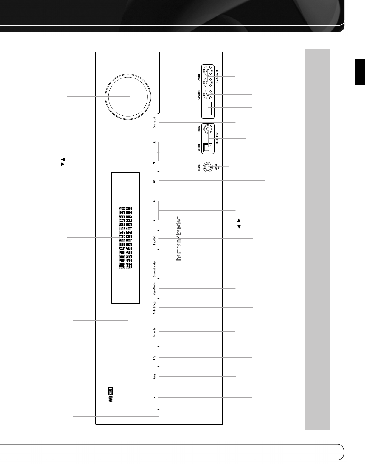
Resolution Navigation
Video
Modes
Source List
Back/Exit
OK
Navigation
Headphone
Jack/EzSet/EQ
Microphone
Input
Digital
Audio Inputs
(Optical and
Coaxial Front)
Remote
IR Sensor
Video
Front Input
USB
Port
Analog Audio
Front Inputs
Surround
Modes
Audio
Effects
Setup
Standby/On
Switch
Info
Settings
Volume
Message DisplayPower
Indicator
/
/
FRONT-PANEL CONTROLS
ENGLISH
NOTE: To make it easier to follow the instructions throughout the manual that refer to this illustration, a copy of this page may be downloaded from the Product
Support section at www.harmankardon.com.
7
Page 8

FRONT-PANEL CONTROLS
Power Indicator: This LED has three possible modes:
• Main Power Off: When the AVR is unplugged or the rear-
panel Main Power Switch is off, this LED is off.
• Standby: Amber indicates that the AVR is ready to be turned on.
• On: When the AVR is turned on, this LED turns white.
NOTE: If the PROTECT message ever appears, turn off the
AVR and unplug it. Check all speaker wires for a possible short.
If none is found, bring the unit to an authorized Harman Kardon
service center for inspection and repair before using it again.
Standby/On Switch: This electrical switch turns the
receiver on, or places it in Standby mode for quick turn-on.
Setup Button: Press this button to access the AVR’s main
menu.
Info Settings Button: Press this button to directly access
the AVR’s Source Info submenu, which contains the settings for the
current source.
Resolution: Press this button to access the AVR’s video output
resolution setting: 480i, 480p, 720p, 1080i, 1080p or 1080p/24
(if available on source and display).
IMPORTANT NOTE: If the AVR’s video output resolution
is set higher than the capabilities of the actual connection,
you will not see a picture. If the best available video connection
from the AVR to the TV is composite video, press this button
and change the resolution to 480i.
This jack is also used to connect the supplied microphone for the
EzSet/EQ procedure described in the Initial Setup section.
USB Port: This port may be used in case a software upgrade
for the receiver is offered in the future. Do not connect a storage
device, peripheral product or a PC here, unless instructed to do
so as part of an upgrade procedure.
Digital Audio and Analog Audio/Video Front
Inputs: Connect a source component that will only be used
temporarily, such as a digital camera or game console, to these
jacks. Use only one type of audio and one type of video connection.
NOTE: The AVR’s menus refer to these jacks as the Optical
Front, Coaxial Front, Composite Front, and Analog Front inputs.
Volume Knob: Turn this knob to raise or lower the volume.
Message Display: Various messages appear in this two-line
display in response to commands and changes in the incoming signal.
In normal operation, the current source name appears on the upper
line, while the surround mode is displayed on the lower line. When
the on-screen display menu system (OSD) is in use, the current
menu settings appear.
Remote IR Sensor: This sensor receives infrared (IR)
commands from the remote control. It is important to ensure that it
is not blocked. If covering the sensor is unavoidable, use an optional
Harman Kardon HE 1000, or other infrared receiver, connecting it to
the Remote IR Input on the AVR 2600’s rear panel.
Audio Effects: Press this button to directly access the Audio
Effects submenu, which allows adjustment of the tone and other
audio controls. See the Initial Setup section for more information.
Video Modes: Press this button for direct access to the Video
Modes submenu, which contains settings that may be used to
improve the picture, if necessary, after you have adjusted the
picture settings using the video display or TV.
Surround Modes: Press this button to select a surround
sound (e.g., multichannel) mode. The Surround Modes menu will
appear on screen, and the menu line will appear in the front-panel
display. See the Advanced Functions section for more information
on surround modes.
Source List: Press this button to select a source device,
which is a component where a playback signal originates, e.g., DVD.
Back/Exit: Press this button to return to the previous menu,
or to exit the menu system.
5/17/3 Navigation: These buttons are used to navigate the
AVR’s menus.
OK: Press this button to select the currently highlighted item.
Headphone Jack/EzSet/EQ Microphone
Input: Plug a 1/4" headphone plug into this jack for private
listening.
8
Page 9
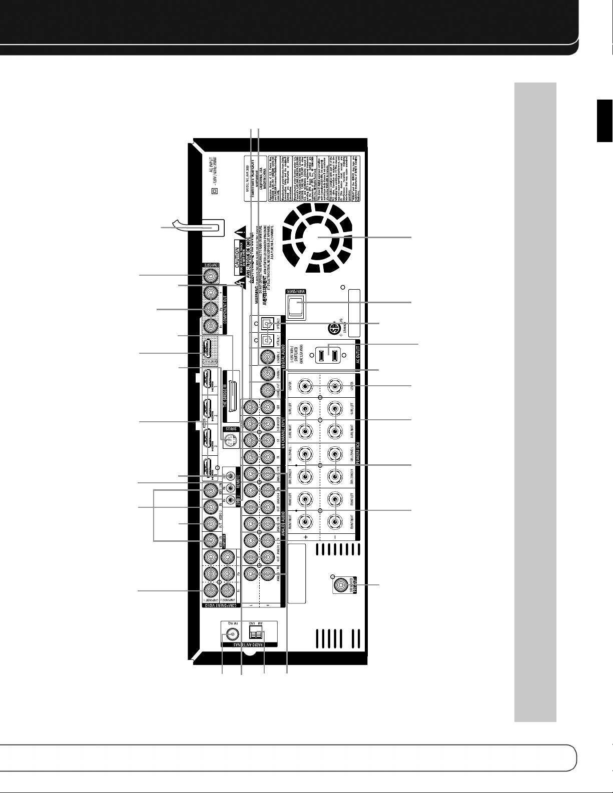
Analog 1–5 Inputs
6/8 Channel
Inputs
Video
1, 2 & 3
Inputs
Remote
IR Input
Zone 2
IR Input
SIRIUS
Tuner
The Bridge III
Remote
IR Output
HDMI 1–4
Inputs
HDMI
Monitor
Output
Video
Monitor
Output
Center
Speaker
Outputs
Switched AC
Accessory
Outlet
Main
Power
Switch
Component
1 & 2
Inputs
Surround
Back/
Zone 2
Speaker
Outputs
Front
Speaker
Outputs
AM Antenna
FM Antenna
Analog 2 & 4
Audo Outputs
Surround
Speaker
Outputs
Component Video
Monitor Output
AC Power Cord
Video 2
Output
Subwoofer
Output
Coaxial
Digital
Audio
Output
Coaxial 1 & 2
Digital Audio Inputs
Optical 1& 2
Digital
Audio
Inputs
Fan Vents
REAR- PANEL CONNECTIONS
ENGLISH
NOTE: To make it easier to follow the instructions throughout the manual that refer to this illustration, a copy of this page may be downloaded from the Product
Support section at www.harmankardon.com.
9
Page 10

REAR- PANEL CONNECTIONS
Main Power Switch: This mechanical switch turns the
power supply on or off. It is usually left on, and cannot be turned
on or off using the remote control.
6-/8-Channel Inputs: Connect the multichannel analog
audio outputs of a non-HDMI player (DVD-Audio, SACD
Disc™or HD-DVD, or any other external decoder) to these jacks.
See page 30 for more information.
™
, Blu-ray
Coaxial 1/2 and Optical 1/2 Digital Audio
Inputs: If a source has a compatible digital audio output, and
if you are not using an HDMI connection for audio for the device,
connect it to one of these jacks to hear digital audio formats, such
as Dolby Digital, DTS and linear PCM. Use only one type of digital
audio connection for each source.
Coaxial Digital Audio Output: If a source is also
an audio recorder, connect the Coaxial Digital Audio Output to the
recorder’s matching input for improved recording quality. Only PCM
digital audio signals are available for recording. Both coaxial and
optical digital audio signals are available at this Digital Audio Output.
SIRIUS Tuner Jack: Connect a SIRIUS satellite radio tuner
module here.
Zone 2 Infrared (IR) Input: Connect a remote IR receiver
located in the remote zone of a multizone system to this jack to
control the AVR (and any source devices connected to the Remote
IR Output) from the remote zone.
Remote Infrared (IR) Input and Output: When the
remote IR receiver on the front panel is blocked, connect an optional
IR receiver to the Remote IR Input jack. The Remote IR Output may
be connected to the Remote IR Input of a compatible product to
enable remote control through the AVR.
HDMI Inputs and Output: HDMI (High-Definition
Multimedia Interface) is a connection for transmitting digital audio
and video signals between devices. Connect up to four HDMIequipped source devices to the HDMI inputs using a single-cable
connection.
When you connect the HDMI Output to your video display, the
AVR 2600 will automatically transcode analog video signals to the
HDMI format, upscaling to as high as 1080p.
NOTE: When connecting a DVI-equipped display to one of
the HDMI Outputs:
• Use an HDMI-to-DVI adapter.
• Make sure the display is HDCP-compliant. If it isn’t, do not connect
it to an HDMI Output; use an analog video connection instead.
• Always make a separate audio connection.
Analog 1 – 5 Inputs: Connect the left and right analog
audio outputs of a source device to any of these inputs. These
inputs may be paired with any video inputs.
NOTES:
• The Analog 2 and 4 inputs are each associated with a set
of outputs. Consider using these connectors for an audio or
video recorder.
• You may optionally connect a source to both an analog and
digital audio input. This is useful for making recordings, for
multizone applications or simply as a backup.
Analog 2 and 4 Outputs: Connect either of these analog
audio outputs to the analog audio inputs of a recording device.
A signal is available at these outputs whenever an analog audio
source is playing.
Subwoofer Output: If you have a powered subwoofer
with a line-level input, connect it to the Subwoofer Output.
The Bridge III Input: Connect a Harman Kardon
docking station (not included) to this input for use with most docking
iPod models, 4G and later, iPhone or iPhone 3G (not included). Turn
the receiver off (Standby mode) when connecting The Bridge III.
Fan Vents: This area contains vents used by the AVR 2600’s
fan to cool the system. Maintain a clearance of at least 3 inches
from the nearest surface to avoid overheating the unit. It is normal
for the fan to remain off at most normal volume levels. An automatic
temperature sensor turns the fan on only when it is needed.
IMPORTANT NOTE: Never block the fan vents, as doing
so could allow the AVR to overheat to dangerous levels.
Video 1/2 / 3 Inputs: Use these jacks to connect your videocapable source components (e.g., VCR, DVD player, cable TV box) to
the receiver. Use only one type of video connection for each source.
Video 2 Output: Connect this analog video output to the
composite video input of a recording device. A signal is available
at this output whenever an analog video source is playing.
Video Monitor Output: If any of your sources use
composite video connections, connect this monitor output to the
corresponding input on your video display. If your video display
is equipped with HDMI or component video inputs, this connection
is unnecessary, as the AVR 2600 will convert the composite video
source signal to the correct format for a single video-cable
connection to the TV.
Component Video 1/2 Inputs: If a video source has
analog component video (Y/Pb/Pr) capability, and if you are not
using an HDMI connection, connect the component video outputs
of the source to one of the sets of component video inputs. Do not
make any other video connections to that source.
Component Video Monitor Outputs: If you are
using one of the Component Video Inputs and your television or
video display is component-video-capable (but does not have an
HDMI input), connect these jacks to the video display.
10
Page 11

REAR- PANEL CONNECTIONS
NOTES:
• Due to copy-protection restrictions, there is no output at
the Component Video Monitor Outputs for HDCP-copyprotected sources.
• Composite video signals are upscaled to as high as 1080i
and available at these outputs. If your video display’s best
connection is component video, it is the only video connection required from the AVR to the display.
AM and FM Antenna Terminals: Connect the included
AM and FM antennas to their respective terminals for radio reception.
Front, Center and Surround Speaker Outputs:
Use two-conductor speaker wire to connect each set of terminals
to the correct speaker. Remember to observe the correct polarity
(positive and negative connections).
Surround Back/Zone 2 Speaker Outputs: These
speaker outputs are used for the surround back channels in a 7.1channel home theater, or may be reassigned to a remote room for
multizone operation.
Switched AC Accessory Outlet: You may plug the
AC power cord of one source device into this outlet, and it will turn
on whenever you turn on the receiver. Do not use a source that
consumes more than 50 watts of power.
ENGLISH
AC Power Cord: After you have made all other connections,
plug the AC power cord into an unswitched wall outlet.
11
Page 12
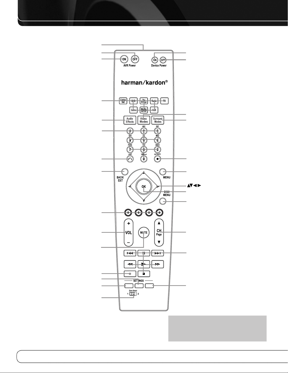
SETUP
INFO SLEEP
AVR Power Off
AVR Power On
Source Selectors
Audio Effects
Alphanumeric Keys
Soft keys
Volume
Mute
Device Power On
Device Power Off
Surround Modes
Video Modes
OK
Navigation
Activity
Menu
Disc Menu
Channel
Sleep Settings
Transport Controls
IR Transmitter Lens
Last
Back/Exit
Record
Info Settings
Setup
Zone Selector
MAIN REMOTE CONTROL FUNCTIONS
12
NOTE: To make it easier to follow the instructions
throughout the manual that refer to this illustration,
a copy of this page may be downloaded from the
Product Support section at www.harmankardon.com.
Page 13

MAIN REMOTE CONTROL FUNCTIONS
The AVR 2600 remote is capable of controlling 8 devices, including
the AVR itself and an iPod docked in an optional The Bridge III.
During the installation process, you may program the codes for
each of your source components into the remote. To operate a
component, press its Selector button to change the device mode.
Each Source Selector has been preprogrammed to control certain
types of components, with only the codes specific to each brand
and model changing, depending on which product code is programmed. The AUX and Cable/SAT Source Selectors may be used
for multiple device types, depending on the first digit of the product
code. Other Source Selectors may be reassigned to other device
types (see Initial Setup section).
AUX Source Selector: CD player product codes begin
with 0, 1 or 2. VCR codes begin with 3 or 4. HDTV set-top box
codes begin with 6, PVD codes begin with 7 and TiVo®set-top box
codes begin with 8.
Cable/SAT Source Selector: Cable set-top box codes begin
with 0, 1 or 2, and satellite set-top box codes begin with 3 or 4.
IMPORTANT NOTE: All of the AVR 2600’s audio and
video inputs are independently assignable. Select the inputs
to which the device is physically connected during Initial
setup. Any device may be connected to any compatible input
and given any name (e.g., DVD or Game).
Most of the buttons on the remote have dedicated functions,
although the precise codes transmitted vary depending on the
device mode. Due to the wide variety of functions for various source
devices, we have included only a few of the most-often used
functions on the remote: alphanumeric keys, transport controls,
television-channel control, menu access and power on and off.
Buttons dedicated to the AVR are available at any time, even in
another device mode: AVR Power On and Off, Audio Effects, Video
Modes, Surround Modes, Volume, Mute and Sleep Settings. Press
the Setup Button near the bottom of the remote to return it to
AVR mode.
A button’s function depends on which component is being controlled.
See Table A13 in the appendix for listings of the functions for each
type of component.
IR Transmitter Lens: As buttons are pressed on the
remote, infrared codes are emitted through this lens.
AVR Power On Button: Press to turn on the AVR. The
Master Power Switch on the rear panel must be on.
Device Power Off Button: Press a device’s Source
Selector, then press this button to turn off the device.
Device Power On Button: Press a device’s Source
Selector, then press this button to turn on the device.
Mute Button: Press to mute the AVR 2600’s speaker and
headphone outputs. To end the muting, press this button, adjust
the volume, or turn off the receiver.
AVR Power Off Button: Press to turn off the AVR 2600.
Source Selectors: Press one of these buttons to select a
source device, e.g., DVD, CD, cable TV, satellite or HDTV tuner. This
will also turn on the receiver and switch the remote’s device mode
to operate the source. The first press of the Radio Selector switches
the AVR to the last-used tuner band (AM, FM or SIRIUS). Each successive press changes the band.
While the DVD Source Selector may be used to operate either a
Harman Kardon Blu-ray Disc player or a Harman Kardon DVD player,
the default mode is to operate a Harman Kardon Blu-ray Disc player.
To toggle between Harman Kardon Blu-ray Disc player and DVD player
operation, press and hold the DVD Source Selector for 2 seconds.
The source selector will flash twice to confirm that the remote’s mode
has changed to operate the other type of disc player.
Audio Effects: Press to directly access the Audio Effects
submenu, which allows adjustment of the AVR’s tone and other
audio controls. See the Initial Setup section for more information.
Video Modes: Press for direct access to the Video Modes
submenu, which contains picture settings to be used after you have
adjusted the picture settings on the video display or TV. See the
Advanced Functions section for more information.
Surround Modes: Press to directly access the Surround
Modes submenu. Select a Surround mode category: Auto Select,
Virtual Surround, Stereo, Movie, Music or Video Game. The surround
mode will change when the menu line is highlighted.
To change the surround mode for the selected category, press the
OK Button when the menu line is highlighted and select one of the
available surround mode options, using the 5/1 Buttons. Press the
OK Button, or press the Back/Exit Button to exit the Surround Modes
menu and display the next higher menu in the hierarchy.
See the Advanced Functions section for more information on
surround modes.
Sleep Settings Button: Press to activate the sleep timer,
which turns off the receiver after a programmed period of time of
up to 90 minutes. Each press increases the timer by 10 minutes,
ending with the “Sleep Off” message.
Volume Control: Press to raise or lower the volume.
Navigation
buttons are used to make selections within the menu system and
to operate the tuner.
(
5/17/3
)
and OK Buttons: These
Alphanumeric Keys: Use these buttons to enter numbers
for radio station frequencies or to select station presets.
Last Channel: When controlling a cable, satellite or HDTV
set-top box or a TV, press this button to return to the previous
television channel.
Activity: With this button, up to eleven Activities may be
programmed to transmit a series of commands with a single press.
Execute an Activity by pressing this button, then the Alphanumeric
Key (or the AVR Power On or Off Button) into which it was programmed.
See the Advanced Functions section for more information on Activities.
Back/Exit: Press to return to the previous menu or to exit the
menu system.
ENGLISH
13
Page 14

MAIN REMOTE CONTROL FUNCTIONS
Menu Button: This button is used within the Now Playing
menu for the tuner (including SIRIUS Radio), and The Bridge III, and
to display the main menu on some source devices. To display the
AVR 2600’s main menu, press the Setup Button.
Disc Menu: While a DVD is playing, press the DVD Source
Selector, then this button, to display the disc’s menu.
Soft Keys: These buttons are used with some source devices.
See Table A13 in the appendix for details. They are also used with
a Teletext-capable television if your broadcast, cable or satellite
provider offers Teletext service.
Channel/Page Control: When the tuner has been selected,
this control selects a preset radio station. While operating a cable,
satellite or HDTV set-top box or a television, press these buttons to
change channels.
Record Button: Use this button to make recordings when an
audio or video recorder is in use.
Setup Button: Press to display the AVR’s Main Menu, or to
switch the remote to AVR device mode.
Info Settings Button: Press to display the AVR’s Info
Menu, which contains the settings for the current source.
Zone Selector: Use this switch to select whether AVR
commands will affect the main listening area (Zone 1) or the remote
zone of a multizone system (Zone 2). For normal operation, leave
the switch in the Zone 1 position.
Track Skip: These buttons are used with source components
to change tracks or chapters.
Transport Controls: These buttons are used to control
source components and The Bridge III.
14
Page 15

INTRODUCTION TO HOME THEATER
This introductory section will help you to familiarize yourself with
some basic concepts unique to multichannel surround sound
receivers, which will make setup and operation smoother.
Typical Home Theater System
A home theater typically includes an audio/video receiver, which
controls the system; a disc player; a source component for television
broadcasts (cable box, satellite dish receiver, HDTV tuner or antenna
connected to the TV); a video display (television); and loudspeakers.
Multichannel Audio
The main benefit of a home theater system is the placement
of loudspeakers around the room to produce “surround sound.”
Surround sound immerses you in the presentation for increased
realism.
The AVR 2600 may have up to seven speakers connected directly
to it, plus a subwoofer. Each main speaker is powered by its own
amplifier channel inside the receiver. A system with more than two
speakers is called a multichannel system.
• Front Left and Right – The main speakers are used as
in a 2-channel system. In many surround modes, these speakers
are secondary, while the main action, especially dialogue, is
moved to the center speaker.
• Center – The center speaker is used for dialogue in movies
and television programs, allowing the dialogue to originate near
the actors’ faces, for a more natural sound.
• Surround Left and Right – The surround speakers
improve directionality of ambient sounds. In addition, more loudspeakers play dynamic soundtracks without risk of overloading
any one speaker.
power of an explosion, adding realism and excitement to your
home theater. Some people use two subwoofers, for additional
power and even distribution of the sound.
Surround Modes
There are different theories as to the best way to present surround
sound and to distribute information to the speakers. A variety of
algorithms have been developed in an effort to reproduce the way we
hear sounds in the real world, resulting in a rich variety of options.
Several companies have taken surround sound in different directions:
• Dolby Laboratories – Dolby TrueHD, Dolby Digital Plus,
Dolby Digital, Dolby Digital EX, Dolby Pro Logic II and IIx
• DTS – DTS-HD High Resolution Audio, DTS-HD Master Audio,
DTS, DTS-ES (Discrete and Matrix), DTS Neo:6, DTS 96/24
• Harman International (the Harman Kardon
parent company) – Logic 7, Harman Virtual Speaker,
Harman Headphone
• Stereo Modes – Generic modes that expand upon conventional 2-channel stereo, including 5- and 7-channel stereo
Table A13 in the appendix contains detailed explanations of the
mode groups and the mode options available within each group.
Digital modes, such as Dolby Digital and DTS, are only available
with specially encoded programs, such as HDTV, Blu-ray Disc media
and digital cable or satellite television. Other modes may be used
with digital and analog signals to create a different surround presentation, or to use a different number of speakers. Surround Mode
selection depends upon the number of speakers in your system, the
materials you are watching or listening to, and your personal tastes.
ENGLISH
• Surround Back Left and Right – Additional surround
speakers may be placed behind the listening position, improving the
precision of ambient sounds and allowing for more realistic pans.
The surround back speakers are used with surround modes
designed for 7.1-channel systems, such as Dolby Digital EX,
Dolby Digital Plus, Dolby TrueHD, DTS-ES (Discrete and Matrix),
DTS-HD High Resolution Audio, DTS-HD Master Audio and Logic 7
(7.1 modes). The surround back speakers are optional, and the
AVR 2600 may be set up with a 5.1-channel system in the main
listening area, and the surround back channels reassigned to a
multizone system, where the surround back channels power
loudspeakers located in another room.
Many people expect the surround speakers to play as loudly as
the front speakers. Although all of the speakers in the system will
be calibrated to sound equally loud at the listening position, most
artists use the surround speakers for ambient effects only, and
they program their materials to steer very little sound to these
speakers.
• Subwoofer – A subwoofer is designed to play only the lowest
frequencies (the bass). It augments smaller, limited-range satellite
speakers used for the other channels. Many digital-format programs,
such as movies recorded in Dolby Digital, contain a low-frequency
effects (LFE) channel which is directed to the subwoofer. The LFE
channel packs the punch of a rumbling train or airplane, or the
15
Page 16
CONNECTIONS
SubwooferPreout
12 3
There are different types of audio and video connections used
to connect the receiver, the speakers, the video display, and the
source devices. The Consumer Electronics Association has established the CEA®color-coding standard. See Table 1.
Table 1 – Connection Color Guide
Audio Connections
Left Right
Front (FL/FR)
Center (C)
Surround (SL/SR)
Surround Back (SBL/SBR)
Subwoofer (SUB)
Digital Audio Connections
Coaxial
Optical
Video Connections
Component Y Pb Pr
Composite
S-Video
HDMI™ Connections (digital audio/video)
HDMI
White Red
Green
Blue Gray
Brown Tan
Purple
Orange
Input Output
Green Blue Red
Yellow
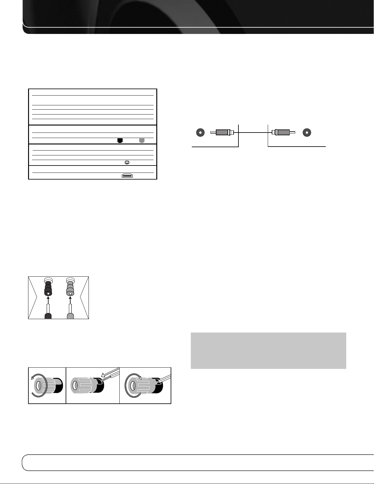
Speaker Connections
Speaker cables carry an amplified signal from the receiver’s speaker
terminals to each loudspeaker. They contain two wire conductors,
or leads, inside plastic insulation, that are differentiated in some
way, such as with colors or stripes.
The differentiation preserves polarity, without which low-frequency
performance can suffer. Each speaker is connected to the receiver’s
speaker-output terminals using two wires, one positive (+) and one
negative (–). Always connect the positive terminal on the speaker,
which is usually colored red, to the positive terminal on the receiver,
which is colored as indicated in the Connection Color Guide (Table 1).
The negative terminals are both black.
The AVR 2600 uses binding-post
speaker terminals that can accept
banana plugs or bare-wire cables.
+
Banana plugs are inserted into the
hole in the middle of the terminal
cap. See Figure 1.
Figure 1 – Binding-Post Speaker Terminals With Banana Plugs
Bare wire cables are installed as follows (see Figure 2):
1. Unscrew the terminal cap until the pass-through hole is revealed.
2. Insert the bare end of the wire into the hole.
3. Hand-tighten the cap until the wire is held snugly.
Subwoofer
The subwoofer is dedicated to the low frequencies (bass), which
require more power. To obtain the best results, most speaker
manufacturers offer powered subwoofers that contain their own
amplifier. Usually, a line-level (nonamplified) connection is made
from the receiver’s Subwoofer Output to a corresponding jack
on the subwoofer, as shown in Figure 3.
Although the purple subwoofer outputs look similar to full-range
analog audio jacks, they are filtered to allow only the low frequencies
to pass. Don’t connect these outputs to any other devices.
Figure 3 – Subwoofer
CONNECTING SOURCE DEVICES
TO THE AVR
Audio and video signals originate in “source devices,” including
your Blu-ray Disc or DVD player, CD player, DVR (digital video
recorder) or other recorder, tape deck, game console, cable or
satellite television box, an iPod or iPhone docked in the optional
The Bridge III docking station or MP3 player. The AVR’s tuner
also counts as a source, even though no external connections
are needed, other than the FM and AM antennas and the SIRIUS
tuner module.
Separate connections are required for the audio and video portions
of the signal, except for digital HDMI connections. The types of
connections used depend upon the capabilities of the source device
and video display.
Audio Connections
There are two types of audio connections: digital and analog.
Digital audio signals are required for listening to sources encoded
with digital surround modes, such as Dolby Digital and DTS, or for
noncompressed PCM digital audio. There are three types of digital
audio connections: HDMI, coaxial and optical. Do not use more
than one type of digital audio connection for each source device.
However, it’s okay to make both analog and digital audio connections to the same source.
NOTE: HDMI signals may carry both audio and video. If your
video display device has an HDMI input, make a single HDMI
connection from each source device to the AVR. Usually, a
separate digital audio connection is not required. Turn the
volume on your television all the way down.
Figure 2 – Binding-Post Speaker Terminals With Bare Wires
16
Digital Audio
The AVR 2600 is equipped with four HDMI (High-Definition
Multimedia Interface) inputs, and one output. HDMI technology
enables digital audio and video information to be carried using
a single cable, delivering the highest quality picture and sound.
The AVR 2600 uses HDMI (V.1.3a with Deep Color) technology and
is capable of processing both the audio and video components
of the HDMI data, minimizing the number of cable connections
in your system. The AVR 2600 implements Deep Color, which
increases by an order of magnitude the shades of color that can
Page 17
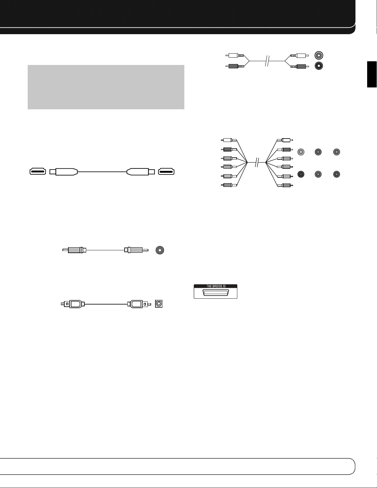
CONNECTIONS
A
Optical
Optical digital
audio cable
Coaxial
Coaxial digital
audio cable
be displayed, and the latest lossless multichannel audio formats,
including Dolby TrueHD and DTS-HD Master Audio.
NOTE: Some DVD-Audio, SACD, Blu-ray Disc and HD-DVD
players only output multichannel audio through their multichannel analog outputs. Make a separate analog audio connection in addition to the HDMI connection, which is still used
for video and to listen to Dolby Digital, DTS or PCM materials
that may be stored on the disc.
The AVR 2600 converts analog video signals to the HDMI format,
including its on-screen menus, upscaling to high-definition 1080p
resolution.
The HDMI connector is shaped for easy plug-in (see Figure 4). If
your video display has a DVI input and is HDCP-compliant, use an
HDMI-to-DVI adapter (not included). A separate audio connection
is required. HDMI cable runs are limited to about 10 feet.
Figure 4 – HDMI Connection
If your video display or source device is not HDMI-capable, use one
of the analog video connections (composite or component video)
and a separate audio connection.
Coaxial digital audio jacks are usually color-coded in orange.
Although they look similar to analog jacks, you should not connect
coaxial digital audio outputs to analog inputs or vice versa. See
Figure 5.
Figure 5 – Coaxial Digital Audio
Optical digital audio connectors are normally covered by a shutter
to protect them from dust. The shutter opens as the cable is inserted.
Input connectors are color-coded using a black shutter, while outputs
use a gray shutter. See Figure 6.
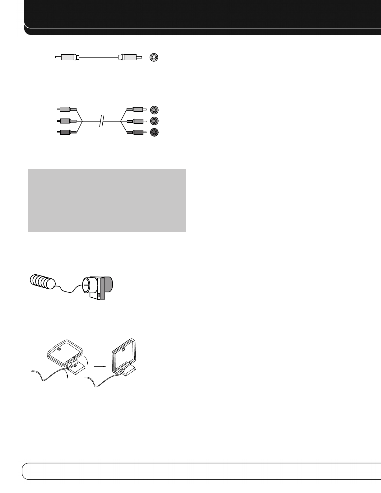
nalog audio
cable (RCA)
Figure 7 – Analog Audio
L
R
The 6-/8-Channel Inputs are multichannel analog connections that
are used with high-definition sources that decode the copy-protected
digital content, such as some DVD-Audio, SACD, Blu-ray Disc and
HD-DVD players. See Figure 8. The multichannel analog audio connection is not required for players compliant with HDMI version 1.1
or better, or that output linear PCM signals via an HDMI connection.
Consult the owner’s guide for your disc player for more information,
and see page 27.
Front Surround Center
Multichannel
analog audio
cable (RCA)
Figure 8 – Multichannel Analog Audio
White
Blue Green
Subwoofer
Red Gray Purple
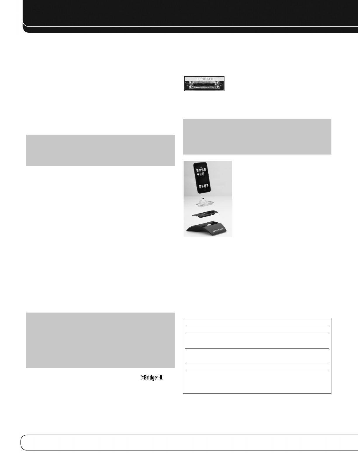
The AVR 2600 also includes a proprietary, dedicated connection for
The Bridge III docking station for the iPod or iPhone. If you own a
docking iPod (most models, 4G or later), iPhone or iPhone 3G, connect
The Bridge III (not included) to The Bridge III port on the receiver. See
Figure 9. Dock your iPod or iPhone (not included) in The Bridge III, and
you may listen to your audio materials through your high-performance
audio system. You may view still images or video materials stored
on a photo- or video-capable iPod that supports video browsing or
iPhone. Use the AVR 2600 remote to control the iPod, with navigation messages displayed on the front panel and on a video display
connected to the AVR. The Bridge III outputs analog audio to the
AVR 2600, and is available to the multizone system.
Figure 9 – The Bridge III port
ENGLISH
Figure 6 – Optical Digital Audio
Analog Audio
Two-channel analog connections require two cables, one for the
left channel (white) and one for the right channel (red). These two
cables are often attached to each other. See Figure 7.
For sources that are capable of both digital and analog audio, you
may make both connections.
The analog audio connection is required for multizone operation,
as the AVR 2600’s multizone system is not capable of converting
a digital signal to analog format. Use the analog audio connections
with the Surround Back/Zone 2 speaker outputs, in case another
2-channel digital audio source is in use in the main listening area.
The AVR 2600 is only capable of processing one PCM source at a time.
You may only record materials from DVDs or other copy-protected
sources using analog connections. Remember to comply with all copyright laws, if you choose to make a copy for your own personal use.
Video Connections
Many sources output both audio and video signals (e.g., Blu-ray
Disc or DVD player, cable television box, HDTV tuner, satellite box,
VCR, DVR). In addition to the audio connection, make one type of
video connection for each of these sources (only one at a time for
any source).
Digital Video
If you have already connected a source device to one of the HDMI
inputs, you have automatically made a video connection, as the
HDMI signal includes both digital audio and video components.
Analog Video
There are two types of analog video connections used on the
AVR 2600: composite video and component video.
Composite video is the basic connection most commonly available.
The jack is usually color-coded yellow, and looks like an analog
audio jack. Do not plug a composite video cable into an analog
or coaxial digital audio jack, or vice versa. Both the chrominance
(color) and luminance (intensity) components of the video signal
are transmitted using a single cable. See Figure 10.
17
Page 18
CONNECTIONS
Composite
video cable
Figure 10 – Composite Video
Component video separates the video signal into three components – one luminance (“Y”) and two sub-sampled color signals
(“Pb” and “Pr”) – that are transmitted using three separate cables.
See Figure 11.
Green
Y
Component
video cable
Figure 11 – Component Video
Pb
Blue
Red
Pr
If it’s available on your video display, an HDMI connection is recommended as the best quality connection, followed by component
video, and then composite video.
NOTES:
• HDCP-copy-protected sources are not available at the
Component Video Monitor Outputs.
• Standard and high-definition analog video signals may
be upscaled to 1080i resolution for the Component Video
Monitor Outputs. For improved video performance, consider
upgrading to an HDMI-capable video display with 1080p
resolution.
with standard audio connections, labeled for “car and home use,”
you will not be able to enjoy the AVR 2600’s ease of control.
USB PORT
The USB Port on the AVR 2600 is used only for software upgrades.
If an upgrade for the receiver’s operating system is released in the
future, it may be downloaded to the AVR using this port. Complete
instructions will be provided at that time.
ANTENNAS
The AVR 2600 uses separate terminals for the included FM and AM
antennas.
The FM antenna uses a 75-ohm F-connector. See Figure 12.
Figure 12 – FM Antenna
The AM loop antenna needs to be assembled. Connect the two leads
to the spring terminals on the receiver. The AM antenna leads have
no polarity, and you may connect them to either terminal. See
Figure 13.
Figure 13 – AM Antenna
To enjoy SIRIUS satellite radio, purchase a SIRIUS-Ready tuner module
and a subscription to the SIRIUS service. Visit www.sirius.com
for information on SIRIUS-Ready tuner modules. The AVR 2600 is
compatible with the SiriusConnect SC-H1 tuner module, using the
8-pin DIN cable included with the module, and it provides power for
the tuner module, so that it is not necessary to use the AC adapter
supplied with the tuner module. Although you may use a module
18
Page 19
SPEAKER PLACEMENT
C
Alternate placement
for Side Surround
Left Speaker
(Blue)
Alternate placement
for Side Surround
Right Speaker
(Gray)
110°
150°
110°
150°
30° 30°
FR
FL
SL
SR
Green
SUB
Purple
Red
Gray
Blue
White
C
90°
150°
90°
150°
30° 30°
SBRSBL
FR
FL
SL
SR
Green
Purple
Red
Gray
Tan
Brown
Blue
White
SUB
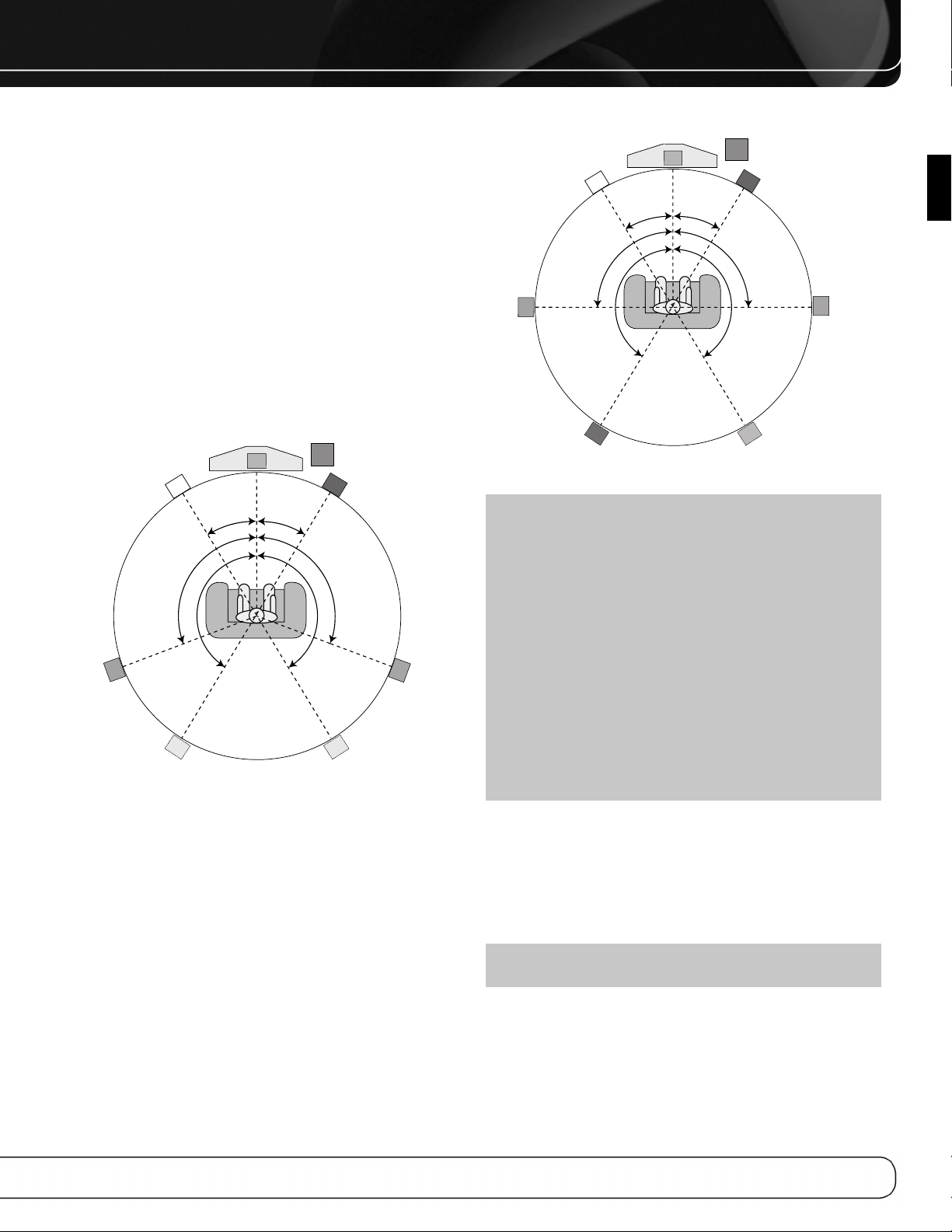
Optimally, the speakers should be placed in a circle with the listening
position at its center. The speakers should be angled so that they
directly face the listening position.
Front Speaker Placement
The center speaker is placed either on top of, below or mounted on
the wall above or below the video display screen.
The front left and right speakers are placed along the circle, about
30 degrees from the center speaker and angled toward the listener.
Place the front left/right and center speakers at the same height,
preferably at about the same height as the listener’s ears. The
center speaker should be no more than 2 feet above or below
the left/right speakers. If you’re using only two speakers with
the AVR 2600, place them in the front left and right positions.
Placement of the surround speakers depends on the number of
speakers in your system.
Figure 14 – Speaker Placement (5.1-Channel System)
Placement of Surround Speakers in a
5.1-Channel System
The side surround speakers should be placed 110 degrees from
the center speaker, slightly behind and angled toward the listener.
Alternatively, place them behind the listener, with each surround
speaker facing the opposite-side front speaker. See Figure 14.
The surround speakers may be placed a little higher than the
listener’s ears.
Placement of Surround Speakers in a
7.1-Channel System
In a 7.1-channel system, the side surround speakers are placed
90 degrees from the center speaker, directly to either side of the
listening position. The surround back left and right speakers are
placed 150 degrees from the center speaker, or directly facing the
opposite-side front speaker. See Figure 15.
ENGLISH
Figure 15 – Speaker Placement (7.1-Channel System)
NOTE: Some speaker manufacturers offer 6.1-channel
speaker systems, for 6.1-channel surround sound formats,
such as Dolby Digital EX, DTS-ES Discrete and Matrix modes
and DTS Neo:6 mode. Using the AVR 2600 in a 6.1-channel
configuration is not recommended. The 6.1-channel formats
will sound better when played through a 7.1-channel system.
The same surround back channel information is played
through both surround back speakers, but with twice the
power and clarity.
To use the AVR 2600 with a 6.1-channel speaker system,
place the single surround back speaker directly behind
the listener, but do not connect it until after you have run
the EzSet/EQ procedure for a 5.1-channel system. After
the EzSet/EQ process finishes, connect the surround back
speaker to the Surround Back Left Speaker Output. Then
follow the directions in the Advanced Functions section for
manual setup of the surround back speaker.
Subwoofer Placement
Placement of the subwoofer requires less precision, since lowfrequency sounds are omnidirectional. Placing the subwoofer close
to a wall or in a corner will reinforce the low frequencies, and may
create a “boomy” sound. Temporarily place the subwoofer where
the listener normally sits, then walk around the room until the low
frequencies sound best. Place the subwoofer in that spot.
NOTE: Your receiver will sound its best when the same
model or brand loudspeaker is used for all positions.
19
Page 20

GETTING STARTED
Installing the AVR 2600 and connecting it to the other system components
can be complicated. To simplify installation, it is suggested that you
design your system before you begin connecting wires and cables.
Although the rear-panel jacks allow for a variety of audio and video
connections to other components, the AVR’s software organizes
the connections into six conventional sources: Cable/SAT, DVD, TV,
Game, Media Server and AUX. The internal sources (the optional
The Bridge III dock for iPod, and the Radio) will be explained later.
Table A1 in the appendix indicates the default device types for
each source, and the default audio/video connection assignments.
If the defaults suit your system, then connect your devices to the
audio/video inputs shown. Otherwise, design your system as
explained below.
1. Best video connection type for your system:
Examine the video inputs on your TV or video display. Write down
the best available video connection type here: ____________.
The options, in order of preference, are: HDMI, DVI (must be HDCPcompliant), component video or composite video. This is the
“system-best” video connection for your system.
2. Decide which source will be used for each
device: Match up to six devices to the six conventional sources
listed in the Table 2 worksheet below. Use the AUX source for any
of these device types: CD player, HDTV set-top box, personal video
recorder (PVR), TiVo device or VCR.
NOTE: You may match any device type to any source. The
device type is only relevant for programming control codes
into the handheld remote and, as explained on page 24, you
may reassign any Source Selector’s device type. Any audio or
video source may be connected to any matching jack on the
AVR, regardless of device type.
3. Best video connection for each source: Examine
each source device and write down the best available type of video
connection, but not better than the system-best connection. Leave
blank audio-only sources, such as a CD player.
4. Best audio connection for each source: For each
source device, write down the best available type of audio connection.
See the note below, and if the HDMI connection may be used for
audio, it is the best option. The other options, in order of preference,
are: optical digital audio, coaxial digital audio, 2-channel analog audio.
NOTES:
• For multichannel disc players, if both the device and the
TV use HDMI connections for video, then check the owner’s
manual for the device to determine whether it transmits
multichannel audio via its HDMI output. If it does, then no
separate audio connection is required. If not, write down
the multichannel analog audio connection in addition to
any other audio type. See page 27 for more information.
• If the device uses an HDCP-compliant DVI output for video,
then connect it to one of the AVR’s HDMI Inputs using an
HDMI-to-DVI adapter, but a separate audio connection will
always be required.
5. Decide which sources to connect to each of
the video inputs: Assign only one unique video input to
each source. Use the best type of video connection available for
each source.
• If your system-best video connection is “HDMI”, select up to
four HDMI source devices and assign them to one of the four
numbered HDMI Inputs.
• If your system-best video connection is “Component”, or if you
have source devices with component video outputs that weren’t
assigned to one of the HDMI Inputs, assign up to two devices
to one of the two numbered Component Video Inputs.
• If your system-best video connection is “Composite Video”, or if
you have source devices with composite video outputs that have
not been assigned to any other video input, then assign up to three
devices to one of the three numbered composite video Inputs.
NOTE: If the source device is a video recorder that will
be used to record from other devices connected to the AVR,
assign the recorder to the Video 2 Input, which has a recording output. Any of the Coaxial or Optical Digital Inputs may be
assigned to the recorder for audio, if it is capable of making
digital audio recordings. To make analog recordings, assign
either the Analog 2 or 4 Audio Inputs to the recorder, as both
have recording outputs. It is not necessary to connect TiVo or
PVR devices that will only record from their direct cable or
satellite television signals to the AVR’s recording outputs.
Table 2 – Source Assignment Worksheet
Source Device Type Best Video Video Input Best Audio Audio Input Analog Audio
Connection Assigned Connection Assigned (may Input for
(HDMI, DVI, (HDMI, Optical, be one digital Recording or
Component, Coaxial, 2-Ch plus one or more Multizone
Composite) Analog, 6-/8-Ch analog) Operation
Analog)
Cable/SAT
DVD
TV
Game
Media Server
AUX
20
Page 21

6. Decide which audio inputs to connect to each
source: Assign only one unique digital audio input to each digital
source. Assign analog audio inputs to analog sources, or as secondary
connections for digital sources for backup, for recording or to make
the source available to the multizone system.
• Any source using an HDMI Input requires no additional connection
for audio
• For any source whose best audio connection is optical or coaxial
digital audio, assign one of the three Optical or three Coaxial
Digital Audio Inputs. Do not connect both types of digital audio
to the same source device.
• You may assign one of the 2-Channel Analog Audio Inputs to
a digital source.
• You may also assign the 6-/8-Channel Analog Audio Inputs,
if available, to a digital source. See page 27.
• Assign one of the six 2-channel Analog Audio Inputs to an
analog source.
unless:
The source doesn’t output multichannel audio through its HDMI
output. Make a second connection to the 6-/8-Channel Analog
Audio Inputs.
The source has an HDCP-compliant DVI output for video only.
Assign a digital or analog audio input.
GETTING STARTED
ENGLISH
NOTE: If the source device is a digital audio recorder, it may
be used with any of the Coaxial or Optical Digital Audio Inputs
and the Coaxial Digital Audio Output. Both coaxial and optical
signals are available at the Coaxial Digital Audio Output. To
make analog recordings, assign either the Analog 2 or 4 Audio
Inputs to the recorder, as both have recording outputs.
21
Page 22
INSTALLATION
You are now ready to begin installing the AVR. Before beginning to
connect the various components to the receiver, turn off all devices,
including the AVR 2600, and unplug their power cords.
Don’t plug
in any of the power cords until you have finished making
all of your connections.
The receiver generates heat. Select a location that leaves several
inches of space on all sides. Avoid completely enclosing the receiver
inside an unventilated cabinet. Place components on separate
shelves rather than stacking them directly on top of the receiver.
Never block the AVR’s ventilation slots on the top and side panels.
Doing so could cause the AVR to overheat, with potentially serious
consequences.
select a location with a sturdy surface finish.
TIP: Label each cable before connecting it, to avoid mistakes.
Write a description of the cable on a blank adhesive label,
e.g., “DVD”, and fold the label around the cable about 6 inches
from the end to be plugged into the AVR.
Almost all of the following installation steps are optional, depending
on your system. Skip any step that does not apply to your system.
Some shelf surface finishes are delicate. Try to
STEP ONE – Connect Source Devices
Leaving all AC power cords unplugged, connect the source devices
to the AVR using the audio and video inputs you assigned in Table 2.
STEP TWO – Connect TV
Connect the system-best video input on the TV to the corresponding
video monitor output on the AVR.
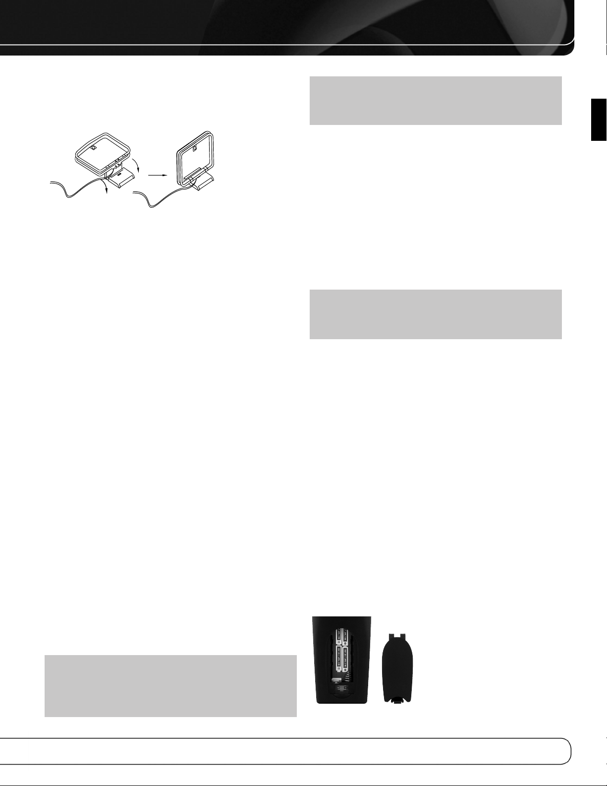
2. Holding the cable with the wider part of the connector at the
bottom, gently squeeze the tabs on each side as you insert it
into the connector on the rear panel.
See Figure 16.
Figure 16 – The Bridge III Connector
3. Place the black insert in The Bridge III, making sure to push it
all the way down. See Figure 17.
NOTE: Do not place an iPod or iPhone in The Bridge III
unless both the black insert and a dock adapter are installed.
Otherwise, the iPod or iPhone will not connect properly, and
both it and The Bridge III may sustain damage that is not
covered by the warranty.
STEP THREE – Connect Loudspeakers
After you have placed your loudspeakers in the room as explained
on page 19, connect each speaker to its color-coded terminal on
the AVR. Maintain proper polarity by connecting the negative terminal
on the speaker (usually colored black) to the negative terminal
on the AVR (also colored black); and the positive terminal on the
speaker (usually red) to the positive terminal on the AVR (color
varies by channel; see Table 1 on page 16).
If you have a subwoofer, connect its line-level or LFE input to the
purple Subwoofer Output.
NOTE: If the subwoofer only has speaker-level inputs, after
you have configured the AVR using EzSet/EQ technology as
described on page 25, connect the subwoofer’s left and right
speaker input terminals to the AVR’s Front Left and Front Right
Speaker Outputs, then connect the front left and right main
speakers to the subwoofer’s left and right speaker output
terminals. Consult the owner’s manual for the subwoofer for
specific installation instructions.
STEP FOUR – Connect Optional
Dock
To enjoy content stored on a compatible iPod or iPhone (not included):
1. Turn off the AVR, using its Standby/On Switch.
Figure 17 – Docking an iPod or iPhone in The Bridge III
4. Locate the dock adapter that was included with your iPod or
iPhone, or select one of the included dock adapters by referring
to Table 3. If your iPod or iPhone does not appear in Table 3 and
did not include an adapter, contact Apple Inc. to purchase one.
Place the adapter in The Bridge III insert, as shown in Figure 17.
5. Remove the iPod or iPhone from any case, and dock it in
The Bridge III, as shown in Figure 17.
Table 3 – Select the Correct The Bridge III Insert
The Bridge III Insert iPod Model
NANO iPod nano, 1st and 2nd generation
5G (VIDEO 60GB) iPod, 5th generation (60GB, 80GB),
and iPod classic (160GB)
5G (VIDEO 30GB) iPod, 5th generation (30GB), and
iPod classic (80GB)
13 iPod nano, 3rd and 4th generation
12, 14 iPod touch – install large bumper;
iPhone or iPhone 3G – install small
bumper
STEP FIVE – Connect FM Antenna
Connect the included FM antenna to the 75-ohm FM antenna terminal.
22
Page 23
INSTALLATION
STEP SIX – Connect AM Antenna
Assemble the included AM antenna (see Figure 18) and connect it
to the AM and Ground antenna terminals. The antenna is not polarized, and either lead may be connected to either terminal.
Figure 18 – AM Antenna Assembly
STEP SEVEN – Connect SIRIUS Tuner
Module
If you have purchased an optional SIRIUS tuner module designed
for SIRIUS-Ready devices, plug it into the SIRIUS jack. Purchase
a subscription and activate the module, following the instructions
posted at www.sirius.com. Place the module within view of a
south-facing window.
STEP EIGHT – Connect Remote IR Inputs
and Outputs
The AVR 2600 is equipped with a Remote IR Input, a Zone 2 Input
and a Remote IR Output to facilitate use of your system with a
remote control in a variety of situations.
When the AVR 2600 is placed inside a cabinet or facing away from
the listener, connect an external IR receiver, such as the optional
Harman Kardon HE 1000, to the Remote IR Input jack. For multizone
operation, connect an optional IR receiver, keypad or other control
device to the Zone 2 IR Input for remote control of the AVR 2600
(and any sources connected to the AVR’s Remote IR Output) from
the remote zone. Signals transmitted through the Zone 2 IR Input will
control source selection and volume for the main or remote zone,
depending on the setting of the remote’s Zone Selector. If a source
device is shared with the main listening area, any control commands
issued to that source will also affect the main room.
If any source devices are equipped with a compatible Remote IR
Input, use a 1/8-inch mini-plug interconnect cable (not included)
to connect the AVR’s Remote IR Output to the source device’s
Remote IR Input.
To control more than one source device through the Remote IR
Output, connect all sources in “daisy chain” fashion, connecting
each device’s IR output to the next device’s IR input, starting with
the AVR.
STEP NINE – Install a Multizone System
The AVR 2600 offers the ability to distribute audio to other areas in
your home.
so may present a safety hazard. If you have any doubt about
your ability to work with electrical and telecommunications
wiring, hire a licensed electrician or custom installer to install
the multizone system.
Multizone operation takes over the Surround Back/ Zone 2 amplifier
channels, limiting the system in the main listening room to 5.1
channels.
1. Connect the remote room’s speakers directly
to the Surround Back/Zone 2 Speaker Outputs.
Reassign the Surround Back amplifier channels to power the
speakers (see page 42).
2. Connect IR Control Devices to the Zone 2 IR
Input
Connect an IR control device to the Zone 2 IR Input for remote-room
control of the multizone system, source devices and volume in the
remote zone.
NOTE: Only analog audio sources are available to the multizone system. For digital sources, make a second, analog audio
connection. The Bridge III source is available to the multizone
system.
STEP TEN – Plug in AC Power Cords
Before plugging the AVR into an unswitched electrical outlet, make
sure the Main Power Switch on the rear panel is off, to prevent the
possibility of damaging the AVR in case of a transient power surge.
You may plug one device that draws no more than 50 watts into
the AC Switched Accessory Outlet on the rear panel. Turn on the
device’s mechanical or master power switch, and that device will
power on any time the AVR 2600 is turned on (some devices may
require additional steps to power on from their standby mode). If the
device has a clock or must always be on (such as a cable set-top
box programmed to make recordings), do not plug it into this outlet.
Plug the AC Power cord into an unswitched AC outlet.
It is recommended that you copy the appropriate information from
the Table 2 worksheet to Table A5 in the appendix for future reference, in the event changes are made to the system components.
STEP ELEVEN – Insert Batteries in Remote
The AVR 2600 remote control uses four AAA batteries (included).
To remove the battery cover located on the back of the remote,
squeeze the tab and lift the cover.
Insert the batteries as shown in Figure 19, observing the correct
polarity.
ENGLISH
IMPORTANT SAFETY NOTE: Installing a multizone
system typically requires running cables inside walls. Always
comply with the appropriate safety codes when installing concealed wiring, particularly all applicable state and local building codes and the NEC (National Electrical Code). Failure to do
Figure 19 – Remote Battery Compartment
23
Page 24

INSTALLATION
Point the remote’s lens toward the front panel of the AVR 2600.
Make sure no objects, such as furniture, are blocking the remote’s
path to the receiver. Bright lights, fluorescent lights and plasma
video displays may interfere with the remote’s functioning. The
remote has a range of about 20 feet, depending on the lighting
conditions. It may be used at an angle of up to 30 degrees to either
side of the AVR.
Leave the Zone Selector Switch at the bottom in the Zone 1 position
for normal use.
If the remote control seems to operate intermittently, or if pressing
a button on the remote does not cause the Setup Button or one of
the Source Selectors to light, check or replace the batteries.
STEP TWELVE – Program Sources Into
the Remote
The AVR 2600 remote may be programmed to control many brands
and models of DVD players, cable boxes, satellite receivers, the
Harman Kardon DMC 1000 digital media center and TVs. It is also
preprogrammed to operate your iPod when docked in The Bridge III.
To access the functions for a particular device, switch the remote’s
device mode. Press the Setup Button to access the codes that control
the receiver, or the Source Selector Buttons to access the codes for
the devices programmed into the remote.
While the DVD Source Selector may be used to operate either a
Harman Kardon Blu-ray Disc player or a Harman Kardon DVD player,
the default mode is to operate a Harman Kardon Blu-ray Disc player.
To toggle between Harman Kardon Blu-ray Disc player and DVD player
operation, press and hold the DVD Source Selector for 2 seconds.
The source selector will flash twice to confirm that the remote’s
mode has changed to operate the other type of disc player.
Follow these steps to program the correct codes for each source
device into the remote:
1. Look up the codes for the product type (e.g., DVD, cable TV box)
and the brand name of your source in Tables A14– A24 of the
Appendix.
NOTE: The AUX Source Selector is used for CD, HDTV, PVD
recorder, TiVo and VCR device types. Similarly, the Cable/SAT
Source Selector is used for either a cable or satellite TV settop box. The first digit of the product code indicates the
device type.
2. Turn on your source device.
3. Place the remote in program mode: Press and hold the Source
Selector as it turns red, goes dark, and turns red again. Then
release it.
Optional: To reassign a Source Selector’s device type (e.g., if
there are two DVD players in the system), press the Source Selector
for the new device type now. For example, to reassign the Cable/SAT
Source Selector to operate a DVD player, first press and hold the
Cable/SAT Button, then press the DVD Button.
The remote control is preprogrammed at the factory to operate
a Harman Kardon Blu-ray Disc player when in DVD device mode.
It is not necessary to change the device type to program a DVD
player’s codes.
4. Enter a code from Step 1, above.
a) If the device turns off, press the Source Selector again to save
the code. It will flash and the remote will exit Program mode.
b) If the device does not turn off, enter another code. If you run
out of codes, search through all of the codes in the remote’s
library for that product type by pressing the
repeatedly until the device turns off. When the device turns
off, save the code by pressing the Source Selector. It will flash,
and the remote will exit Program mode.
5. Check that other functions control the device correctly. Sometimes
manufacturers use the same Power code for several models,
while other codes vary. Repeat this process until you’ve programmed a satisfactory code set that operates most functions.
6. Find out which code number you have programmed by pressing
and holding the Source Selector to enter the Program mode.
Press the OK Button, and the Source Selector will flash in the
code sequence. One flash represents “1”, two flashes for “2”, and
so forth. A series of many fast flashes represents “0”. Record the
codes programmed for each device in Table A9 in the appendix.
Most of the button labels on the remote describe the button’s
function when used to control the AVR 2600. However, the button
may perform a different function when used to control another
device. Refer to the Remote Control Function List, Table A13 in
the Appendix.
Activities are preprogrammed code sequences that execute many
code commands with a single button press. “Punch-through”
programming allows the remote to operate a device’s channel or
transport controls with the remote in another device’s mode. See
page 43 for instructions on these advanced programming functions.
or 5Button
1
STEP THIRTEEN – Turn On the AVR 2600
Two steps are required the first time you turn on the AVR 2600.
1. Flip the rear-panel Main Power Switch to the “On” position. The
Power Indicator on the front panel will turn amber, indicating that
the AVR is in Standby mode and is ready to be turned on. Normally,
you may leave the Main Power Switch on, even when the receiver
is not being used.
2. There are several ways to turn on the AVR from Standby mode.
a) Press the Standby/On Switch on the front panel.
b) Using the remote, press the AVR Power On Button or any of
the Source Selectors.
NOTES:
• Any time you press one of the Source Selectors on the
remote, the remote will switch device modes. To control the
receiver, press the Setup Button. Some AVR functions are
available in all device modes: Volume Controls (including
Mute), Audio Effects, Video Modes, Surround Modes, Setup,
Info Settings, Sleep Settings and AVR Power On and Off.
• If you do not see a picture within about one minute, refer
to the Video Troubleshooting Tips on page 30.
24
Page 25
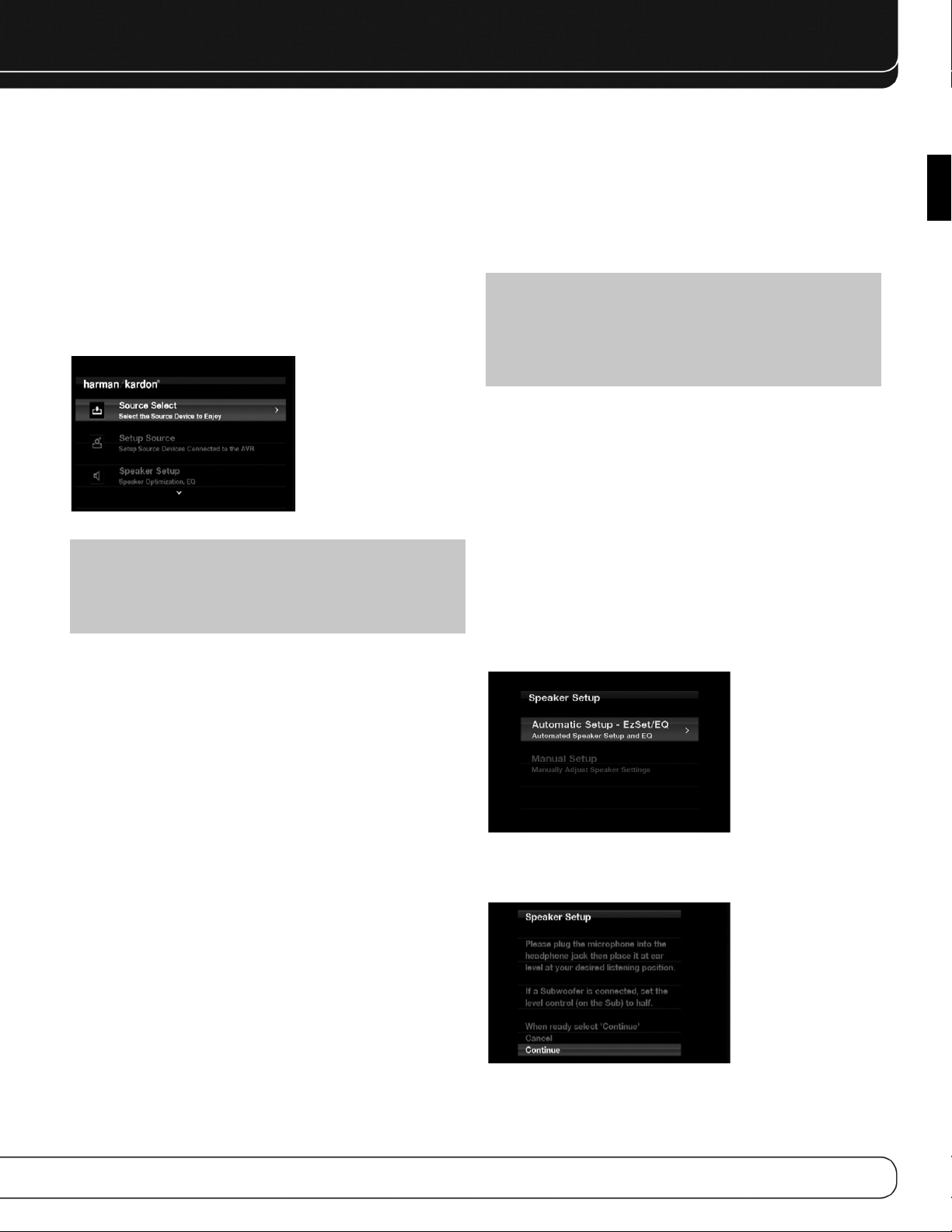
INITIAL SETUP
In this section, you will configure the AVR 2600 to match your actual
system. A video display must be connected to one of the video
monitor outputs on the receiver.
USING THE ON-SCREEN MENU SYSTEM
Although it’s possible to configure the AVR using only the remote
and the front-panel messages, it is easier to use the full-screen
menu system.
The menu system is accessed by pressing the Setup Button on the
remote or front panel.
The Main Menu will appear (see Figure 20), and if a video source
is playing, it will be visible behind the transparent menu.
Figure 20 – Main Menu
NOTE: When using the AVR’s on-screen menu system, a
video output resolution of 720p or higher is recommended for
easiest viewing, and to provide graphics that simplify some
configuration options. Depending on the resolution selected,
the menus shown by your system may vary in appearance.
The main menu system consists of five submenus: Source
Selection, Setup Source, Speaker Setup, Zone 2 and System.
Use the 5/17/3 Buttons on the remote or front panel to navigate
the menu system, and press the OK Button to select a menu or
setting line, or to enter a new setting.
The current menu, setting line or setting will appear in the Message
Display, as well as on screen.
To return to the previous menu or exit the menu system, press the
Back/Exit Button. Be certain all settings are correct, as any changes
you have made will be retained.
Most users should follow the instructions in this Initial Setup section
to configure a basic home theater system. You may return to these
menus at any time to make additional adjustments, such as those
described in the Advanced Functions section.
Before beginning initial setup, all loudspeakers, a video display and
all source devices should be connected. You should be able to turn
on the receiver and view the main menu when you press the Setup
Button. If necessary, reread the Installation Section and the beginning of this section before continuing.
Until recently, most receivers required manual calibration and
configuration, a tedious process that called for a good ear or the
purchase of an SPL (sound-pressure level) meter. Although you may
configure the AVR 2600 manually, as described in the Advanced
Functions section, it is recommended that you take advantage of
the signature Harman Kardon EzSet/EQ system.
Eliminate extraneous background noise, such as noisy air conditioning.
Avoid making any loud noises while running EzSet/EQ setup.
IMPORTANT SAFETY NOTE: During the EzSet/EQ
procedure, a series of very loud test sweeps will be played
through all of the speakers. Avoid sitting or standing close to
any one speaker during the procedure. If you are particularly
sensitive to loud noises, you may wish to leave the room and
have someone else run the EzSet/EQ process.
STEP ONE – Place the included EzSet/EQ microphone in the
listening position or in the center of the room, at about the same
height as the listeners’ ears. The microphone features a threaded
insert on the bottom, for mounting on a camera tripod.
STEP TWO – Plug the EzSet/EQ microphone into the
Headphone Jack/EzSet/EQ Microphone Input Jack on the front of
the receiver, and set the level control on the subwoofer to the
halfway point.
STEP THREE – Turn on the AVR 2600 and the video
display. Press the Setup Button to display the Main Menu. Use
the 5 Button to highlight the Speaker Setup line, then press the
OK Button. See Figure 21.
Figure 21 – Speaker Setup Menu Screen
Select “Automatic Setup-EzSet/EQ”, and the screen shown in
Figure 22 will appear.
ENGLISH
Configure the AVR 2600, Using EzSet/EQ
Technology
One of the most important steps in setting up a home theater
system is to calibrate the receiver to match the loudspeakers,
optimizing sound reproduction.
Figure 22 – EzSet/EQ Screen
To return to the Speaker Setup menu without starting the EzSet/EQ
process, select Back. When you are ready to begin, select Continue.
25
Page 26
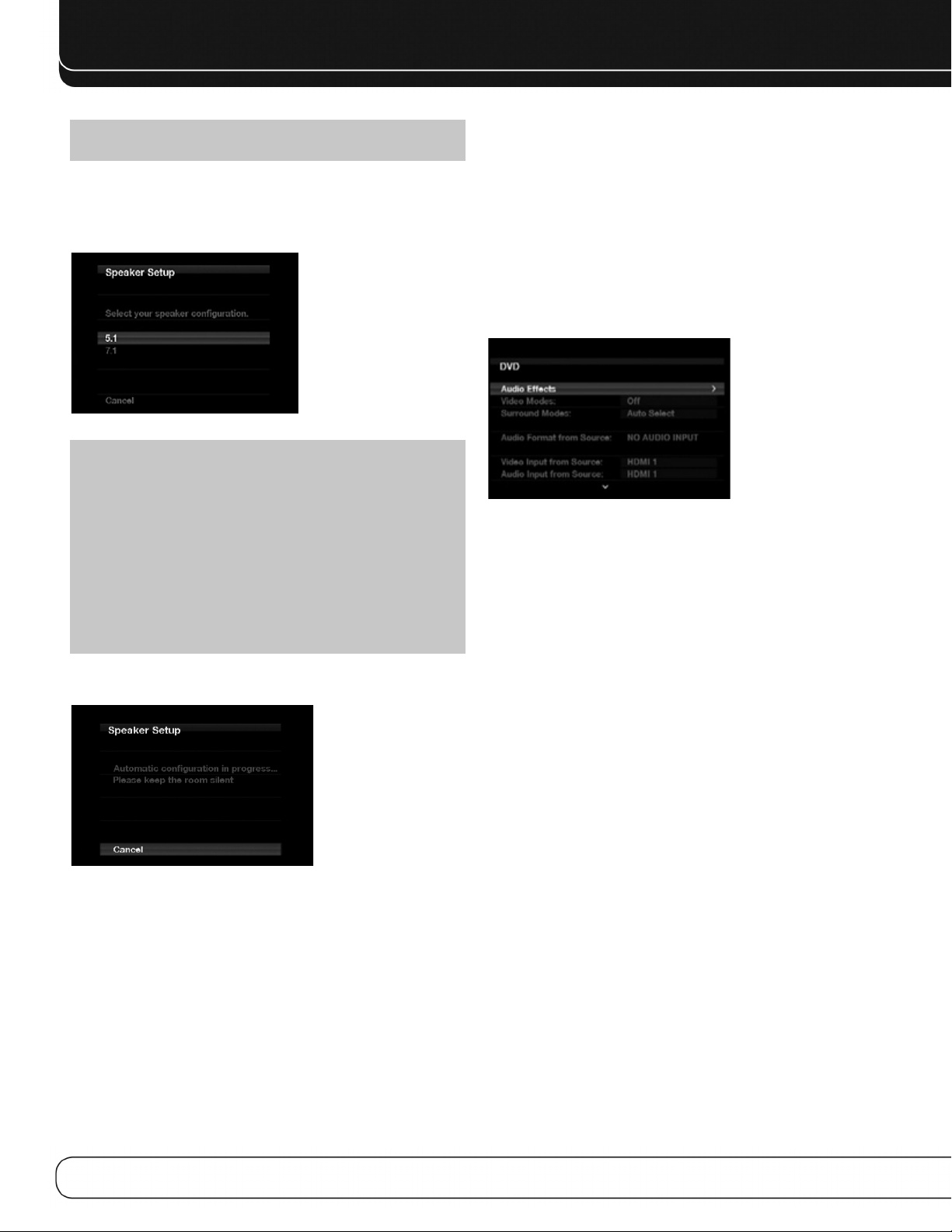
INITIAL SETUP
NOTE: The AVR 2600 will automatically set its master
volume to – 25dB.
STEP FOUR – After you select “Continue”, the screen shown
in Figure 23 will appear. Select the number of speakers in your
system. Select 5.1 if no surround back speakers are present or if
the surround back channels will be used for multizone operation.
Figure 23 – EzSet/EQ: Number of Speakers
NOTE: If there are fewer than five main speakers in your
system, do not use the EzSet/EQ process. Instead, proceed
as described in the Advanced Functions section. If you have
selected a 6.1-channel configuration with a single surround
back speaker, use EzSet/EQ automatic configuration for
5.1 speakers, connect the single surround back speaker
to the left Surround Back Speaker Output, then configure
the surround back speaker manually, as described in the
Advanced Functions section. The 6.1-channel configuration
is not recommended. If the subwoofer is to be connected to
the Front Speaker Outputs, do not connect the subwoofer until
after running the EzSet/EQ process.
The test will begin, and the screen shown in Figure 24 will appear.
Maintain silence during the EzSet/EQ configuration.
Set Up Sources
The Info Settings menu is used to assign the correct physical audio
and video connections to each source.
The following settings are not optional and must be adjusted now
to enable playback of each source: Video Input From Source, Audio
Input From Source and Resolution to Display. The other settings
may be adjusted later.
To display the Info Settings menu, press the Info Settings Button
(front panel or remote). Or, from the Main Menu, select the Setup
Source line and select a source from the slide-in menu. A screen
similar to the one shown in Figure 25 will appear.
Figure 25 – Setup Source Menu
Audio Effects: Displays the Audio Effects submenu, where
you may adjust the Dolby Volume setting, the bass and treble tone
controls, the LFE trim, the Equalization On/Off setting and the MP3
enhancement for each source independently. Leave this submenu
at its default settings, and return to it later if your system requires
fine-tuning. See the Advanced Functions section for more information.
Video Modes: Displays the Video Modes submenu, where you
may make picture adjustments for each source independently. Leave
the settings at their factory defaults. Picture adjustments should be
made to your video display first, with this menu used only for finetuning. See the Advanced Functions section for more information.
Figure 24 – EzSet/EQ in Progress
As the EzSet/EQ system tests each speaker, its position will appear
on screen. If the test sweep is heard from a different speaker than
the one indicated on screen, turn off the AVR and check the speakerwire connections, then begin again.
When the test is completed, select the Continue option. These
options will be displayed:
•
View Settings: Select to view the results of the EzSet/EQ
procedure.
Done: Select to return to the Speaker Setup menu.
•
See the Advanced Functions section for instructions on how to
manually configure the speakers or manually adjust the settings
established by the EzSet/EQ process.
26
Surround Modes: Displays the Surround Modes submenu,
where you may program surround modes for movies, music and
games for each source independently.
Digital surround signals, such as Dolby Digital and DTS, are automatically played in their native formats, although you may change
the surround mode. See the Advanced Functions section for more
information.
Audio Format From Source: This line is informational
only. When a digital program is playing, its format will be identified
here. When analog audio programs are playing, this line displays
ANALOG.
Audio and Video Input Selection
See Table A2 in the appendix for the factory default input assignments
for each source. You may assign any available input to any source
using the Info Settings menu.
When a source is selected, the AVR will check the assigned digital
audio input for a signal. If one is present, the digital input will be
selected. If not, the AVR will select the analog audio input specified
at the Audio Auto Polling line of the Info Settings menu. If you don’t
want the AVR to select an analog audio input for the source, leave
this setting at its default of Off.
Page 27

INITIAL SETUP
The AVR will also select the assigned video source. The only “audioonly” sources on the AVR 2600 are the Radio and The Bridge III
(video may be available; see page 32), which use special on-screen
menus. For external sources, if no video signal is present, the display
will remain black. You may pair an audio device with an A/V device’s
video signal using the Info Settings menu. Sources may share audio
or video inputs.
NOTE: The Bridge III obtains its audio and video signals
(when available) from the iPod or iPhone docked in it, and it
may not be used with other audio or video sources.
Video Input From Source: Assign the correct video
input. Refer to Table 2, where you noted the physical video input
the source is connected to, and select that input here.
Audio Input From Source: Assign the correct analog or
digital audio input. Refer to Table 2, where you noted the physical
audio input the source is connected to, and select that input here.
If both analog and digital audio connections were made, select the
digital input here, and select the analog input at the Audio Auto
Polling and Zone 2 Audio lines below.
6-/8-Channel Inputs
The 6-/8-Channel Analog Audio Inputs are used when playing
certain multichannel discs (DVD-Audio, Blu-ray Disc, SACD and
HD-DVD) on a player that decodes the audio and outputs it via its
multichannel analog audio outputs but not via its HDMI output.
HDMI-Equipped Multichannel Disc Player:
• Connect the player’s HDMI output to one of the AVR’s HDMI
Inputs. No other connections are necessary.
• Assign the HDMI Input to both the Audio and Video Input From
Source settings.
HDMI-Equipped Multichannel Disc Player
That Does Not Output Multichannel Audio
via an HDMI Connection:
• Connect the player’s HDMI output and its multichannel analog
audio outputs to one of the AVR’s HDMI Inputs and to the AVR’s
6-/8-Channel Analog Audio Inputs.
• Assign the HDMI Input to both the Audio and Video Input From
Source settings.
• When listening to DVD-Video discs, CDs or other materials outputting standard-definition digital audio, do nothing, as long as
the HDMI Input is assigned to the Audio Input From Source setting.
• To listen to high-resolution multichannel discs, change the Audio
Input From Source setting to “6/8 Channel”. Change it back to the
HDMI Input to listen to standard-resolution digital materials.
Multichannel Disc Player Without HDMI Output,
or When Video Display Has No HDMI Input:
• Connect the player’s component video outputs to one set of
Component Video Inputs on the AVR. Depending on the capabilities
of the player and your video display, you may need to use a
composite video connection instead.
• Connect the player’s digital audio output to a digital audio input
on the AVR.
• Connect the player’s multichannel audio outputs to the AVR’s
6-/8-Channel Analog Audio Inputs.
• Assign the correct digital audio and analog video inputs to the
Audio and Video Input From Source settings.
• When listening to DVD-Video discs, CDs or other materials outputting standard-definition digital audio, do nothing, as long
as the correct digital audio input is assigned to the Audio Input
From Source setting.
• To listen to high-resolution multichannel discs, change the Audio
Input From Source setting to “6/8 Channel”. Change it back to the
digital audio input to listen to standard-resolution digital materials.
NOTE: The 6-/8-Channel Inputs pass the incoming signals
directly to the volume control, without digitizing or processing
them. It is not possible to change the surround mode or adjust
any of the audio controls in the Audio Effects menu when
using the 6-/8-Channel Inputs. Configure the bass management
settings (i.e., speaker size, delay and output level) on your
source device to match the settings programmed using the
EzSet/EQ procedure, which may be viewed using the Speaker
Setup menu (see Advanced Functions section). Consult the
owner’s guide for your multichannel player for more information.
Resolution to Display: This setting reflects the video
output resolution, which is dependent upon the capabilities of the
video display.
• If the display is connected to the AVR’s HDMI Output, the two
devices will communicate with each other, and the AVR will automatically select the best available video output resolution.
• If the display is connected to the AVR’s Component Video Outputs,
there is no automatic detection of the display’s capabilities, and
the video output resolution must be manually adjusted to match
the display’s capabilities (which may be obtained from the display’s
manual or its manufacturer’s Web site).
• If the display is connected to the AVR’s Composite Video Monitor
Output, the video output resolution must be set to 480i (the factory
default) to view any content, including the AVR’s own menus.
Adjust the resolution by pressing the front-panel Resolution Button
and using the 1/5 Buttons until the correct setting appears in the
front-panel Message Display. For composite video, the correct setting
is 480i. For component video, it is the highest resolution where a
picture is visible. You will be prompted to accept or cancel the resolution change; the CANCEL message will appear on the front panel.
Press the
OK Button.
5 Button to view the ACCEPT option, and then press the
NOTE: When the display has a DVI input which is connected
to the AVR using an HDMI-to-DVI adapter, the picture will be
distorted or blank if the display is not HDCP-compliant. In that
case, a different video connection must be used (component
or composite).
ENGLISH
27
Page 28

INITIAL SETUP
Resolution From Source: Informational only. Indicates
the resolution of the video output by the source device.
HDMI Bypass: When an HDMI source signal is in use and
the system includes an HDMI-capable display, the HDMI Bypass
mode passes the source signal directly to the HDMI output, bypassing all video processing within the AVR, including video output
resolution adjustment. To allow the AVR to process all video, including
“blending” the source video with its on-screen messages and
menus so that you may adjust the AVR without missing any portion
of the program, turn this setting off. When the HDMI Bypass mode
is on, it is not possible to “blend” the video source signal with the
AVR’s on-screen menus. When any remote or front-panel buttons
are pressed, the AVR will momentarily exit HDMI Bypass mode and
display the on-screen menu on a black background. After the menu
is cleared from the screen, either by timing out or when the Back/Exit
Button is pressed, the AVR will return to HDMI Bypass mode.
Change Name: Change the display name for your source,
which is useful if your source’s device type is different from the
available source names. Select this line and use the
to scroll forward or reverse through the alphanumeric characters.
When the desired character appears, use the 3 Button to move the
cursor to the next position. Move the cursor again to leave a blank
space. When you have finished, press the OK Button. The name will
appear on the front panel and next to its original name, e.g., DVD,
throughout the on-screen menu system. To clear the entry without
making any changes, scroll to the blank character before “A”.
5/1 Buttons
Zone 2 Audio: Determines the audio source for the multizone
system remote zone. Select the analog audio input the source is
connected to. Digital audio is not available to the multizone system.
Press the Back/Exit Button, then return to the Setup Source line
of the Main Menu to configure the next source. When you have
finished, press the Back/Exit Button to clear the menus from view.
You are now ready to begin enjoying your new receiver!
Adjust Lip Sync: Resynchronizes the audio and video
signals from a source to eliminate a “lip sync” problem. Lip sync
issues can occur when the video portion of a signal undergoes
additional processing in either the source or the video display.
The Lip Sync adjuster appears by itself, enabling you to view the
video while listening to the audio. Use the 7/3 Buttons to delay
the audio by up to 180ms. See Figure 26.
Figure 26 – Adjust Lip Sync
Audio Auto Polling: Used when both analog and digital
audio connections are made. When no digital signal is present, the
AVR will automatically switch to the analog audio input.
This can be useful for older cable television systems that broadcast
channels in both analog and digital audio.
If an analog audio connection was made, select it here. If not, choose
the Off setting, and the AVR will always use the digital audio
connection.
28
Page 29
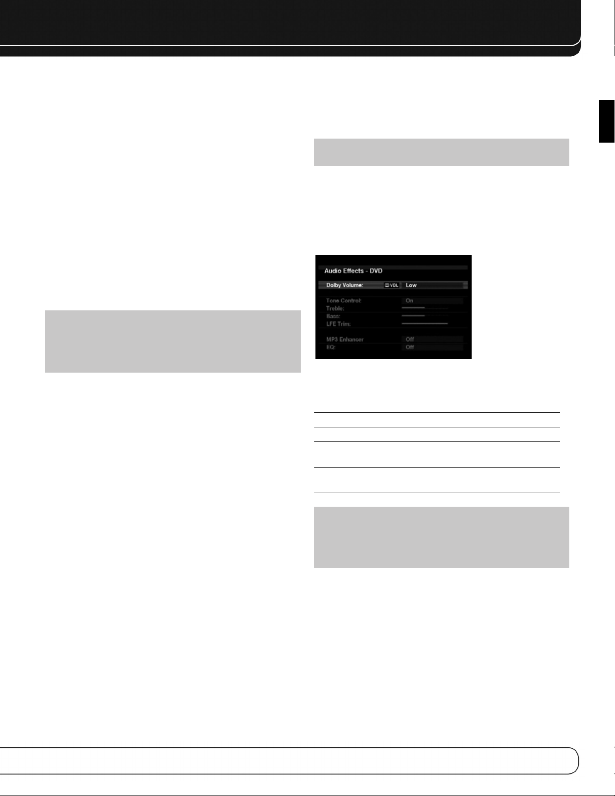
OPERATION
Now that you have installed your components and completed a
basic configuration, you are ready to begin enjoying your home
theater system.
TURNING ON THE AVR 2600
Flip the rear-panel Main Power Switch to the “On” position. The
Power Indicator on the front panel will turn amber, indicating that
the AVR is in Standby mode and is ready to be turned on. The
Main Power Switch is normally left on.
There are several ways to turn on the AVR 2600:
a) Press the Standby/On Switch on the front panel.
b) Using the remote, press the AVR Power On Button or any of the
Source Selectors.
To turn the receiver off, press either the Standby/On Switch on
the front panel or the AVR Power Off Button on the remote control.
Unless the receiver will not be used for an extended period of time,
leave the Main Power Switch on. When the Main Power Switch is
turned off, any settings you have programmed will be preserved for
up to four weeks.
IMPORTANT NOTE: If the PROTECT message ever
appears in the Message Display, turn off the AVR and unplug
it. Check all speaker wires for a short. If none is found, bring
the unit to an authorized Harman Kardon service center for
inspection and repair before using it again.
endeavors to re-create the reference presentation that was heard
in the recording studio without losing portions of the program at
the typically lower volume levels often used in the home. When the
Modeler module is active, you may notice details of the performance
that were hidden when the program was played on other equipment.
NOTE: The Dolby Volume processor is not used to level
volume across sources.
To adjust the Dolby Volume setting, press the Audio Effects Button.
A screen similar to the one shown in Figure 27 will appear. Move
the cursor to highlight the Dolby Volume setting, and each press of
the OK Button will switch to one of the options in Table 4 below. The
settings do not refer to the volume level, which is adjusted normally
using the Volume Control, but rather to the amount of Dolby Volume
processing desired.
Figure 27 – Adjust Dolby Volume
ENGLISH
VOLUME CONTROL
Adjust the volume either by turning the knob on the front panel
(clockwise to increase volume or counterclockwise to decrease
volume), or by pressing the Volume Control on the remote. The
volume is displayed as a negative number of decibels (dB) below
the 0dB reference point.
0dB is the maximum recommended volume for the AVR 2600.
Although it’s possible to turn the volume to a higher level, doing
so may damage your hearing and your speakers. For certain more
dynamic audio materials, even 0dB may be too high, allowing for
damage to equipment. Use caution with regard to volume levels.
To change the volume level display from the default decibel scale
to a 0-to-90 scale, adjust the Volume Units setting in the System
Settings menu, as described on page 42.
Dolby Volume
The AVR 2600 implements Dolby Volume processing, which can
improve the audio performance of the system by revealing subtle
details even at normal home-listening volumes.
One concern of the typical home theater listener is that volumes
can vary widely for different programs played by a source, e.g.,
television commercial advertisements are often much louder than
the main feature. Another is that details heard in the recording
studio at typically high reference volumes are lost at the lower
volumes used by many listeners.
The AVR 2600 uses two Dolby Volume techniques to address these
issues. The Leveler module maintains a consistent listening volume
within a source, e.g., while watching commercial television or while
listening to different tracks on a data CD. The Modeler module
Table 4 – Dolby Volume Settings
Setting Effect
Off No Dolby Volume processing
Low Only Dolby Volume Modeler module is active
Medium Both Modeler and Leveler modules are active;
Leveler module has a value of 3
Max Both Modeler and Leveler modules are active;
Leveler module has a value of 9
NOTE: Dolby Volume processing is compatible with sources
recorded at a sampling rate of 48kHz. High-resolution sources,
such as DTS 96/24, will be decoded at 48kHz. DTS 96/24
programs will be played in DTS 5.1 mode. To hear DTS 96/24
materials in high resolution, turn off Dolby Volume processing.
Dolby Volume Calibration Offset
Calibration Offset is a feature of Dolby Volume processing that
allows you to adjust the calibration of the AVR 2600 to optimally
match your speakers and listening environment. The AVR 2600 is
calibrated with the average speaker sensitivity in mind; however,
different speakers may have different sensitivities. Use Calibration
Offset to adjust the calibration of the AVR 2600 according to the
types of speakers you have.
The average home audio speaker sensitivity is 88dB SPL (8 ohms,
1 watt, 1 meter). Check the sensitivity specification for your loudspeakers, found in the owner’s manual or on the manufacturer’s
Web site. If your speakers have a sensitivity rating greater than
88dB SPL, increase Calibration Offset by the difference between
29
Page 30

OPERATION
your speakers’ sensitivity and 88dB. If they have a sensitivity rating
of less than 88dB SPL, decrease Calibration Offset by the difference
between your speakers’ sensitivity and 88dB.
To adjust the Calibration Offset, press the Setup Button and scroll
to the System Setup menu, then select it. Scroll to the Dolby Volume
Calibration line, which defaults to 0dB. Use the
adjust the setting within the range of –10dB to +10dB.
7/3 Buttons to
MUTE FUNCTION
To temporarily mute all speakers and the headphones, press the
Mute Button on the remote. Any recording in progress will not
be affected. The MUTE message will appear in the display as a
reminder. To restore normal audio, press the Mute Button again,
or adjust the volume. Turning off the AVR will also end muting.
SLEEP TIMER
The sleep timer sets the AVR to play for up to 90 minutes and then
turn off automatically.
Press the Sleep Settings Button on the remote, and the time
until turn-off will be displayed. Each additional press of the Sleep
Button increases the play time by 10 minutes, with a maximum
of 90 minutes. The SLEEP OFF setting disables the sleep timer.
When the sleep timer has been set, the front-panel display will
automatically dim to half-brightness.
If you press the Sleep Button after the timer has been set, the
remaining play time will be displayed. Press the Sleep Button again
to change the play time.
AUDIO EFFECTS
Adjust the Dolby Volume setting, tone controls, LFE trim, Equalization
On/Off setting or MP3 enhancement to improve performance.
Access these settings from the Audio Effects submenu, as described
in the Advanced Functions section.
It is recommended that you leave the settings at their default values
until you are more familiar with your system.
SOURCE SELECTION
Press the front-panel Source List Button. Use the 5/1 Buttons to
scroll through the sources. Using the on-screen menus, press the
Setup Button, highlight “Source Select” and press the OK Button.
Scroll to the desired source in the slide-show menu and press the
OK Button.
For direct access to any source, press its Source Selector on
the remote.
The AVR selects the audio and video inputs assigned to the source,
and any other settings made during setup.
The source name, the audio and video inputs assigned to the
source, and the surround mode will appear on the front panel.
The source name and surround mode will also appear on screen.
VIDEO TROUBLESHOOTING TIPS:
If there is no picture:
• Check the source selection and video input assignment.
• Check the wires for a loose or incorrect connection.
• Check the video input selection on the display device (TV).
• Press the front-panel Resolution Button and use the
5/1 Buttons until the correct video output resolution is
selected and a picture appears. The CANCEL message will
appear. Press the 5Button to view the ACCEPT option, then
press the OK Button.
Additional Tips for HDMI Connections:
• Turn off all devices (including the TV, AVR and any source
components).
• Unplug the HDMI cables, starting with the cable between
the TV and AVR, and continuing with the cables between
the AVR and each source device.
• Carefully reconnect the cables from the source devices to
the AVR. Connect the cable from the AVR to the TV last.
• Turn on the devices in this order: TV, AVR, source devices.
VIDEO MODES
The settings in the Video Modes menu are used to fine-tune the
picture, if necessary, after making all adjustments on the video display.
It is recommended that you leave the settings at their defaults.
See the Advanced Functions section for detailed information.
HEADPHONES
Plug the 1/4-inch plug on a pair of headphones into the front-panel
jack for private listening. The default Headphone Bypass mode
delivers a conventional 2-channel signal to the headphones.
Press the Surround Modes Button on the front panel or the remote,
to switch to Harman Headphone virtual surround processing, which
emulates a 5.1-channel speaker system. No other surround modes
are available for the headphones.
30
USING THE RADIO
To select the AVR 2600’s built-in radio:
1. Press the Source List Button on the front panel. Use the
5/1 Buttons to scroll to the desired band.
2. Press the Radio Source Selector on the remote. Press it again
to switch bands (AM, FM or SIRIUS).
A screen similar to the one shown in Figure 28 will appear.
The SIRIUS band uses a different screen.
Figure 28 – FM Radio
Page 31

OPERATION
Use the 5/1Buttons or the Channel Control to tune a station (or
channel for SIRIUS Radio), as displayed on the front panel and on screen.
The AVR defaults to automatic tuning, meaning each press of the
5/1 Buttons scans through all frequencies until a station with
acceptable signal strength is found. To switch to manual tuning,
in which each press of the 5/1Buttons steps through a single
frequency increment (0.1MHz for FM, or 10kHz for AM), press the
Menu Button. The Mode line will display the current setting. Each
press of the OK Button toggles between automatic and manual
tuning modes.
When an FM station has been tuned, toggling the tuning mode also
switches between stereo and monaural play, which may improve
reception of weaker stations.
A total of 30 stations (AM and FM together) may be stored as presets.
When the desired station has been tuned, press the OK Button, and
two dashes will flash. Use the Alphanumeric Keys to enter the desired
preset number.
To tune a preset station: Press the 7/3 Buttons or the I
Transport Controls; or press the Menu Button and scroll to the
desired preset, then press the OK Button; or enter the preset number
using the Numeric Keys. For presets 10 through 30, press 0 before
the preset number. For example, to enter preset 21, press 0-2-1.
‹‹/››
I
SIRIUS SATELLITE RADIO OPERATION
To listen to Satellite Radio, you’ll need to connect a SIRIUS Satellite
Radio tuner (sold separately) to your SIRIUS Ready receiver. SIRIUS
Satellite Radio is available to residents of the U.S. (except Alaska
and Hawaii) and Canada.
Satellite Radio delivers a variety of commercial-free music from
categories including Pop, Rock, Country, R&B, Dance, Jazz, Classical
and many more, plus coverage of all the top professional and college
sports, including play-by-play games from select leagues and teams.
Additional programming includes expert sports talk, uncensored
entertainment, comedy, family programming, local traffic and weather,
and news from your most trusted sources.
Once you’ve purchased a SIRIUS tuner, you’ll need to activate it and
subscribe to begin enjoying the service. Easy-to-follow installation
and setup instructions are provided with the SIRIUS tuner. There are
a variety of programming packages available, including the option of
adding “The Best of XM” programming.“The Best of XM” service is
not available to SIRIUS Canada subscribers at this time. Please check
with SIRIUS Canada for any updates using the numbers and Web
address below.
Family-friendly packages are also available to restrict channels
featuring content that may be inappropriate for children.
To subscribe to SIRIUS, U.S. and Canadian customers can call 1-888-539-SIRI
(7474) or visit sirius.com (U.S.) or siriuscanada.ca (Canada).
The AVR 2600 is a SIRIUS Ready device, and is able to receive the
SIRIUS service when a user-supplied SIRIUS tuner module is connected
and the service activated.
Select a tuner module designated for SIRIUS Ready audio components.
A SIRIUS Ready module uses the special connector on the AVR and is
controlled by the AVR’s internal tuner, including its 40 preset station
locations and remote control. Although you may use a “car and
home” module with standard audio connections, you will not be able
to enjoy the AVR’s ease of control.
The SIRIUS-Connect SC-H1 tuner module is compatible with the
AVR 2600. Other modules that have standard analog or digital audio
outputs may be connected to a compatible input and operated
using their own controls.
Plug the module into the SIRIUS tuner jack on the rear of the
AVR 2600. Place the tuner module so that it has a clear view through
a south-facing window.
Select SIRIUS Radio as the source in one of these ways:
1. Press the Source List Button on the front panel. Use the
5/1 Buttons to scroll to “SIRIUS Radio” and press the OK Button.
2. Press the Radio Source Selector on the remote repeatedly until
SIRIUS Radio is selected.
There are four ways to tune a SIRIUS Radio channel:
1. Use the
2. Use the 7/3 Buttons to scan through any previously programmed
3. After you have programmed presets, directly enter the preset
4. Press the Menu Button to search for a channel by: preset, category,
When you are able to hear Channel 1, you are ready to activate your
module. If you don’t hear Channel 1, make sure the module’s plug
is firmly seated in the SIRIUS jack, and that the module is near a
south-facing window. Try rotating the module to obtain reception.
You may need to purchase an extension cable to ensure that the
module is near the window.
Tune to Channel 0 for a display of your module’s Radio ID number.
You may also view the Radio ID number by pressing the Menu Button
and selecting “SIRIUS ID”.
The current channel number and preset location will appear in
the lower line of the Message Display. The song title, artist, channel
name, channel category, channel number, preset position (if programmed) and three signal-strength bars, will all appear on screen
when a video display is in use.
For traffic and weather channels, the current city’s name will appear
instead of the channel name, and the local weather and temperature
will be displayed on screen.
A total of 40 channels may be stored as presets. When the desired
channel has been tuned, press the OK Button, and two dashes will
flash in the front-panel display. Use the Alphanumeric Keys to enter
the desired preset number.
To tune a preset, press the
Controls, or press the Menu Button and scroll to the desired preset,
then press the OK Button; or enter the preset number using the
Numeric Keys. For presets 10 through 40, press 0 before the preset
number. For example, to enter preset 21, press 0-2-1.
5/1 Buttons or the Channel Control to scan through
the channel numbers.
preset stations.
number (1 through 40) using the Alphanumeric Keys. For two-digit
positions, enter a “0” before the number.
all channels or direct entry.
7/3Buttons or the I
‹‹/››
I Transport
RECORDING
Two-channel analog and digital audio signals, as well as composite
video signals, are normally available at the appropriate recording
outputs. To make a recording, connect your audio or video recorder
to the appropriate output jacks, as described in the Installation
ENGLISH
31
Page 32
OPERATION
section, insert blank media and make sure the recorder is turned
on and recording while the source is playing.
NOTES:
1. Analog and digital audio signals are not converted to the
other format.
2. Only PCM digital audio signals are available for recording.
Proprietary formats such as Dolby Digital and DTS may not
be recorded using the digital audio connections. Use the
analog audio connections to make an analog recording.
3. HDMI and component video sources are not available for
recording.
4. Please make certain that you are aware of any copyright
restrictions on any material you record. Unauthorized duplication of copyrighted materials is prohibited by federal law.
USING DOCKING STATION
The Bridge III is an optional dock that is compatible with most
docking iPod models, 4G and later, and iPhone models (not included).
When The Bridge III is connected to its proprietary input on the
AVR 2600 and the iPod or iPhone is docked, you may play the
audio, video and still-image materials on your iPod or iPhone
through your high-quality audio/video system; operate the iPod or
iPhone using the AVR remote or the AVR’s front-panel controls;
view navigation messages on the AVR’s front panel or a connected
video display; and charge the iPod or iPhone.
When the source The Bridge is selected and an iPod or iPhone
is docked, the message “The Bridge” appears in the front-panel
Message Display. If the AVR doesn’t detect the iPod or iPhone, turn
off the AVR, remove the iPod or iPhone from The Bridge III and reset
the iPod or iPhone. When the iPod or iPhone returns to its main
menu, redock it and turn on the AVR.
Table 5 summarizes the controls available with The Bridge III during
normal playback.
Table 5 – Using The Bridge III
iPod or iPhone Function Remote Control Key
Play Play (3)
Pause Pause (II)
Menu Menu
)
(
(
3
(33)
(
77
7
)
)
(3)
Back/Exit Back/Exit or Left Arrow
Select OK or Right Arrow
)
(
(
33
1
I )
)
(
5
or Right Arrow
Scroll Reverse Up Arrow
Scroll Forward Down Arrow
Forward Search Forward Search
Reverse Search Reverse Search
Next Track Next
Previous Track Previous ( I77) or Left Arrow (7)
Page Up/Down Page Up/Down
While a selection is playing, the song title and play mode icon will
appear in the front-panel Message Display.
If a video monitor is connected to the AVR 2600 and the system is
not in iPod Manual Mode, the Now Playing screen will appear and
display the play mode icon, song title, artist and album. A graphic
bar indicates the current play position within the track. If random or
repeat play has been programmed, an icon will appear in the upper
right corner.
The screen may disappear from view, depending on the Setup and
Slide-In Menus setting in the System Settings menu (described in
the Advanced Functions section). Restore the Now Playing screen
to view by pressing either of the
NOTE: It is strongly recommended that you use the screen
saver built into your video display to avoid possible damage
from “burn-in” that may occur with plasma and many CRT
displays when a still image, such as a menu screen, remains
on display for an extended period of time.
Press the Menu Button to view the slide-out menu:
Music: Navigates the audio materials stored on the iPod or
iPhone. Use the Page Up/Down Control on the remote to scroll
through the content a page at a time.
Photo/Manual: Select this line to view still images stored on
a photo-capable iPod or iPhone. The system will switch to iPod
Manual Mode, and control will shift to the iPod. Use the screen and
controls on the iPod. The AVR remote may also be used.
To view photos on a video monitor connected to the AVR, select the
photo and press the Play Button on the iPod, or press the OK Button
on the remote three times.
Videos: Select this line to view videos stored on an iPod that
supports video browsing or an iPhone.
NOTES ON VIDEO PLAYBACK:
• As of this writing, video browsing is only supported on the
iPod 5G, iPod classic (80GB, 120GB and 160GB), iPod nano
3G and 4G, and iPod touch or iPhone (when loaded with
software version 2 or higher). For other iPod models, it is
not possible to view photos (except iPod 4G) or videos on
an external monitor while using The Bridge III. Due to the
design of the iPhone, it is not possible to view photos stored
on the iPhone using The Bridge III.
• Before attempting to view photos or videos stored on your
device, check the Video Settings menu on the device and
make sure that the TV Out setting is set to On. The TV
Signal setting should be NTSC, to match the capabilities
of your video display. If your selection was playing and is
paused, the iPod or iPhone requires you to reselect the
video for the new TV Out setting to take effect.
• If you do not see the Videos line in the menu, and the iPod
supports video browsing and has video content stored on
it, you may need to turn off the AVR, remove the iPod from
The Bridge III, reset the iPod, turn the AVR back on and dock
the iPod again. An iPhone may not need to be reset, as simply
undocking and redocking it may resolve the problem. This
7/3 Buttons.
32
Page 33

OPERATION
procedure may also help when a video program is selected
but the “Now Playing” screen appears instead of the video
images.
To exit iPod Manual Mode, with the AVR remote in The Bridge mode,
press the Menu Button. To return to a previous menu level, press
the Back/Exit Button or the
Random: Select this setting for random playback, also known as
“Shuffle Mode”. Each press of the OK Button switches the setting:
shuffle by Song, shuffle by Album, or Off to end random playback.
Repeat: Select this setting to repeat a track or all tracks in the
current album or playlist. Each press of the OK Button switches
the setting: repeat Off, repeat One or repeat All.
NOTE: The iTunes application allows you to exempt some tracks
from Shuffle mode. The AVR 2600 cannot override this setting.
The AVR supports audio playback from some applications available
for the iPhone and the iPod touch. Place the system in iPod Manual
Mode by pressing the Menu Button and selecting “Photo/Manual”.
Then use the controls on the iPhone or iPod touch to run the application. Due to the wide variety of applications and many factors
affecting them, playback is not guaranteed.
While scrolling, hold the key to scroll faster. Use the Page Up/Down
control on the remote to scroll a page at a time (not in manual mode).
NOTES:
• The Play and Pause functions are not available unless
content has been selected for playback.
• To search within a track (not in Manual Mode), press and
hold the indicated button. Press the Previous Track Button
once to skip to the beginning of the current track. Press the
Previous Track Button twice to skip to the beginning of the
previous track.
7 Button.
When a slideshow is being displayed, some controls have different
effects:
• To pause the slideshow, including any audio track that is playing,
press the Pause Button.
• To resume a paused slideshow, press the Pause Button. Pressing
the Play Button begins audio playback.
• To play an audio track stored on the iPod, adjust the Slideshow
Settings on the iPod.
• To skip to the next or previous photo on the iPod, press the Next
or Previous Transport Control.
• It is not possible to skip to the next or previous audio track during
a slideshow.
• To search forward or in reverse within an audio track, press the
Forward or Reverse Search Transport Control. If no audio track is
playing, these controls will have no effect during the slideshow.
SELECTING A SURROUND MODE
Surround mode selection can be as simple or sophisticated as your
individual system and tastes. Feel free to experiment, and you may
find a few favorites for certain sources or program types. More
detailed information on surround modes may be found in the
Advanced Functions section.
To select a surround mode, press the Surround Modes Button
(front panel or remote). The Surround Modes menu will appear
(see Figure 29). Use the 5/1 Buttons repeatedly until the desired
surround mode category appears: Auto Select, Virtual Surround,
Stereo, Movie, Music or Video Game. Press the OK Button to
change the type’s surround mode.
ENGLISH
iPod MANUAL MODE
Press the Menu Button and select Photo/Manual to enter iPod Manual
Mode. This is required to view photos stored on the iPod or iPhone.
Table 6 summarizes the controls available with The Bridge III in
iPod Manual mode.
Table 6 – Using The Bridge III in iPod Manual Mode
iPod Function Remote Control Key
Play Play (3)
Pause Pause (II)
Menu Back/Exit or Left Arrow (7)
Select OK
Select Next Screen* (Scrubber, Right Arrow (
Cover Art, Ratings)
Scroll Reverse Page Up or Up Arrow (1)
Scroll Forward Page Down or Down Arrow (5)
Next Track Next (
Previous Track Previous (
Does not appear on video display connected to AVR.
*
33
)
3
I ) or Right Arrow
I
) or Left Arrow (7)
77
(3)
Figure 29 – Surround Modes Menu
Auto Select: For digital programs, such as movies recorded
with a Dolby Digital soundtrack, the AVR will automatically use the
native surround format. For 2-channel analog and PCM programs,
the AVR uses Logic 7 Movie, Music or Game mode, depending on
the source.
Virtual Surround: When only two main speakers are present
in the system, Harman Virtual Surround may be used to create an
enhanced sound field that virtualizes the missing speakers. Select
between Wide and Reference modes.
Stereo: When 2-channel playback is desired, select the number
of speakers used for playback:
• 2 CH STEREO uses only two speakers. As described on page 35,
you may select Analog Bypass mode for a pure analog signal
when analog audio inputs are in use. Turn off the Tone Control
setting in the Audio Effects submenu, and the AVR does the rest.
33
Page 34

OPERATION
• 5 CH STEREO plays the left-channel signal through the front
and surround left speakers, the right-channel signal through the
right speakers and a summed mono signal through the center
speaker.
• 7 CH STEREO follows the same scheme as 5 CH STEREO, but
adds the surround back speakers. This mode is only available
when the surround back speakers are present and have not
been reassigned to multizone operation. See page 42 for more
information.
Movie: Use when a surround mode is desired for movie playback:
Logic 7 Movie, DTS Neo:6 Cinema or Dolby Pro Logic II (IIx when
seven main speakers are present).
Music: Use when a surround mode is desired for music playback:
Logic 7 Music, DTS Neo:6 Music or Dolby Pro Logic II (IIx when
seven main speakers are present). The Dolby Pro Logic II/IIx Music
mode allows access to a submenu with some additional settings.
See the Advanced Functions section for more information.
Video Game: Use to select a surround mode for game playback:
Logic 7 Game, or Dolby Pro Logic II (IIx when seven main speakers
are present) Game.
After you have made your selection, press the Back/Exit Button.
See the Advanced Functions section for more information on
surround modes.
34
Page 35

ADVANCED FUNCTIONS
Much of the AVR 2600’s performance is handled automatically,
with little intervention required on your part. The AVR 2600 is
capable of being customized to suit your system and your tastes.
In this section, some of the more advanced adjustments available
are described.
AUDIO PROCESSING AND SURROUND
SOUND
Audio signals output by sources are encoded in a variety of formats
that can affect not only the quality of the sound but the number of
speaker channels and the surround mode. You may also manually
select a different surround mode, when available.
Analog Audio Signals
Analog audio signals usually consist of two channels – left and
right. The AVR 2600 offers three options for playback:
1. Analog Bypass Mode: The 2-channel signal is passed
directly from the input to the volume control, without being
digitized or undergoing any processing for bass management
or surround sound. To select analog bypass mode:
a) The analog audio inputs for the source must be selected. If
necessary, press the Info Button on the remote and use the
5/1 Buttons to scroll to the Audio Input from source setting.
b) The tone controls must be disabled by setting the Tone
Control to Off. Press the Audio Effects Button to access the
Tone Control setting.
c) The 2-channel Stereo mode must be selected. Press the
Surround Modes Button to access the STEREO line of the
Surround Modes submenu. Press the OK Button to select
2-channel Stereo.
When the Tone Control setting is Off, the front speakers will
be set to Large automatically. When the Tone Control setting
is turned On, if you have set the front speaker crossover to
a numeric setting, the front speakers will return to the Small
setting.
NOTE: Audio from The Bridge III source is analog, and when
2-channel Stereo mode is selected, the audio will be played in
Analog Bypass mode.
2. DSP Surround Off Mode: The DSP Surround Off mode
digitizes the incoming signal and applies the bass management
settings, including speaker configuration, delay times and output
levels. Select this mode when your front speakers are small,
limited-range satellites and you are using a subwoofer. To select
this mode, use a digital audio input, or turn the Tone Control
setting off, and select 2-channel Stereo mode.
3. Analog Surround Modes: The AVR 2600 is able to
process 2-channel audio signals to produce multichannel surround sound, even when no surround sound has been encoded
in the recording. Among the available modes are the Dolby
Pro Logic II/IIx modes, the Harman Virtual Speaker modes, the
DTS Neo:6 modes, the Logic 7 modes and the Stereo modes.
Digital Audio Signals
Digital audio signals offer greater capacity, which allows the
encoding of center and surround channel information directly
into the signal. The result is improved sound quality and startling
directionality, since each channel is reproduced discretely.
Even when only two channels are encoded, the digital signal
allows for a higher sampling rate that delivers greater detail.
High-resolution recordings sound extraordinarily distortion-free,
especially at high frequencies.
Surround Modes
Surround mode selection is dependent upon the format of the
incoming audio signal, as well as personal taste. Table A13 offers a
brief description of each mode and indicates the types of incoming
signals or digital bitstreams the mode may be used with. Additional
information about the Dolby and DTS modes is available on the
companies’ Web sites: www.dolby.com and www.dtsonline.com.
When in doubt, check the jacket of your disc for more information
on which surround modes are available. Usually, nonessential
sections of the disc, such as trailers, extra materials or the disc
menu, are only available in Dolby Digital 2.0 (2-channel) or PCM
2-channel mode. If the main title is playing and the display shows
one of these surround modes, look for an audio or language setup
section in the disc’s menu. Also, make sure your player’s audio
output is set to the original bitstream rather than 2-channel PCM.
Stop play and check the player’s output setting.
For any incoming signal, only a limited number of surround
modes are available. Although there is never a time when all of
the AVR 2600’s surround modes are available, there is usually
a wide variety of modes available for a given input.
Multichannel digital recordings are found in the 5.1-, 6.1- or 7.1channel formats. The channels included in a 5.1-channel recording
are front left, front right, center, surround left, surround right and
LFE. The LFE channel is denoted as “.1” to represent the fact that
it is limited to the low frequencies.
6.1-Channel recordings add a single surround back channel, and
7.1-channel recordings add surround back left and surround back
right channels to the 5.1-channel configuration. New formats are
available in 7.1-channel configurations. The AVR 2600 is able to
play the new audio formats, delivering a more exciting home theater
experience.
NOTE: To use the 6.1- and 7.1-channel surround modes,
the Surround Back channels must be enabled. See the Manual
Speaker Setup section on page 36 for more information.
The Digital formats include Dolby Digital 2.0 (two channels only),
Dolby Digital 5.1, Dolby Digital EX (6.1), Dolby Digital Plus (7.1),
Dolby TrueHD (7.1), DTS-HD High-Resolution Audio (7.1), DTS-HD
Master Audio (7.1), DTS 5.1, DTS-ES (6.1 Matrix and Discrete), DTS
96/24 (5.1), 2-channel PCM modes in 32kHz, 44.1kHz, 48kHz or
96kHz, and 5.1 or 7.1 multichannel PCM.
When a digital signal is received, the AVR 2600 detects the encoding
method and the number of channels, which is displayed briefly as
three numbers, separated by slashes (e.g., “3/2/.1”).
ENGLISH
35
Page 36

ADVANCED FUNCTIONS
The first number indicates the number of front channels in the signal:
“1” represents a monophonic recording, usually an older program
that has been digitally remastered or, more rarely, a modern
program for which the director has chosen a special effect.
“2” indicates the presence of the left and right channels, but no
center channel.
“3” indicates that all three front channels (left, right and center)
are present.
The second number indicates whether any surround channels are
present:
“0” indicates that no surround information is present.
“1” indicates that a matrixed surround signal is present.
“2” indicates discrete left and right surround channels.
“3” is used with DTS-ES bitstreams to represent the presence
of the discrete surround back channel, in addition to the side
surround left and right channels.
“4” is used with 7.1-channel digital formats to indicate the presence
of two discrete side surround channels and two discrete back
surround channels.
The third number is used for the LFE channel:
“0” indicates no LFE channel.
“.1” indicates that an LFE channel is present.
The 6.1-channel signals – Dolby Digital EX and DTS-ES Matrix
and Discrete – each include a flag meant to signal the receiver to
decode the surround back channel, indicated as 3/2/.1 EX-ON for
Dolby Digital EX materials, and 3/3/.1 ES-ON for DTS-ES materials.
Dolby Digital 2.0 signals may include a Dolby Surround flag indicating
DS-ON or DS-OFF, depending on whether the 2-channel bitstream
contains only stereo information, or a downmix of a multichannel
program that can be decoded by the AVR’s Dolby Pro Logic decoder.
By default, these signals are played in Dolby Pro Logic IIx Movie mode.
When a PCM signal is received, the PCM message and the sampling
rate (32kHz, 44.1kHz, 48kHz or 96kHz) will appear.
When only two channels – left and right – are present, the analog
surround modes may be used to decode the signal into the remaining channels. If you would prefer a different surround format than
the native signal’s digital encoding, press the Surround Modes
Button to display the Surround Modes menu (see Figure 30).
The Auto Select option uses the native signal’s digital encoding,
e.g., Dolby Digital, DTS, Dolby TrueHD or DTS-HD Master Audio.
For 2-channel materials, the AVR defaults to Logic 7 Movie mode.
If you prefer a different surround mode, select the surround mode
category: Virtual Surround, Stereo, Movie, Music or Video Game.
Press the OK Button to change the mode.
Each category is set to a default surround mode:
• Virtual Surround: Harman Virtual Speaker
You may select a different mode. The choice of surround modes
depends on the number of speakers in your system.
• Virtual Surround: Harman Virtual Speaker
• Stereo: 2-channel stereo, 5-channel stereo or 7-channel stereo
• Movie: Logic 7 Movie, DTS Neo:6 Cinema, Dolby Pro Logic II
Movie, Dolby Pro Logic IIx Movie
• Music: Logic 7 Music, DTS Neo:6 Music, Dolby Pro Logic II
Music, Dolby Pro Logic IIx Music
• Video Game: Logic 7 Game, Dolby Pro Logic II Game, Dolby
Pro Logic IIx Game
Once you have programmed the surround mode for each type of
audio, select the line from the Surround Modes menu to override
the AVR’s automatic surround mode selection. The AVR will use the
same surround mode the next time the source is selected.
Please refer to Table A13 in the appendix for more information on
which surround modes are available with different bitstreams.
Dolby Surround Settings
Some additional settings are available for Dolby modes. When the
Dolby Pro Logic II or IIx Music modes have been selected, choose
the Edit submenu to adjust the Center Width, Dimension and
Panorama settings. See Figure 30.
Figure 30 – Dolby Pro Logic II/IIx Music Mode Settings
Center Width: This setting affects how vocals sound through
the three front speakers. A higher number (up to 7) focuses the
vocal information tightly on the center channel. Lower numbers
broaden the vocal soundstage. Use the 7/3 Buttons to adjust.
Dimension: This setting affects the depth of the surround presentation, allowing you to “move” the sound toward the front or rear
of the room. The setting of “0” is a neutral default. Setting “F-3”
moves the sound toward the front of the room, while setting “R-3”
moves the sound toward the rear. Use the
Panorama: With the Panorama mode turned ON, some of the
sound from the front speakers is moved to the surround speakers,
creating an enveloping “wraparound” effect. Each press of the
OK Button toggles the setting on or off.
7/3 Buttons to adjust.
• Stereo: 7-channel stereo
• Movie: Logic 7 Movie
• Music: Logic 7 Music
• Video Game: Logic 7 Game
36
MANUAL SPEAKER SETUP
The AVR 2600 is flexible and may be configured for most speakers,
and to compensate for the acoustic characteristics of your room.
The EzSet/EQ process automatically detects the capabilities of each
speaker, and optimizes the AVR 2600’s performance. If you are
Page 37

ADVANCED FUNCTIONS
unable to run EzSet/EQ calibration, or if you wish to make further
adjustments, use the Manual Speaker Setup on-screen menus.
Before beginning, place your loudspeakers as explained in the
Speaker Placement section, and connect them to the AVR. Consult
the owner’s guide for the speakers or the manufacturer’s Web site
for the frequency range specification. Although you may set the output levels “by ear,” an SPL (sound-pressure level) meter purchased
at a local electronics store will provide greater accuracy.
Record your configuration settings in Tables A3 through A12 in the
appendix for easy re-entry after a system reset, or if the AVR’s
Master Power Switch is turned off or the unit is unplugged for
more than four weeks.
NOTE: When using the AVR’s Speaker Setup menus, select
a video output resolution of 720p or higher to view graphics
that simplify configuration.
STEP ONE – Determine Speaker
Crossover
Without using the EzSet/EQ process, the AVR 2600 can’t detect
how many speakers you’ve connected to it; nor can it determine
their capabilities. Consult the speaker’s technical specifications
and locate the frequency response, usually given as a range, e.g.,
100Hz – 20kHz (±3dB). Write down the lowest frequency that each
of your main speakers is capable of playing (100Hz in the example)
as the crossover in Table A3 in the appendix. This is not the same
as the crossover frequency listed in the speaker’s specifications.
For the subwoofer, write down the transducer size.
The receiver’s bass management determines which speakers will
be used to play back the low-frequency (bass) portion of the source
program. Sending the lowest notes to small satellite speakers won’t
sound right, and may even damage the speaker. The highest notes
may not be heard at all through the subwoofer.
With proper bass management, the AVR 2600 divides the source
signal at a crossover point. All information above the crossover
point is played through the satellite speaker, and all information
below the crossover point is played through the subwoofer. Each
loudspeaker in your system performs at its best, delivering an
enjoyable sound experience.
STEP THREE – Manual Setup Menu
Now you are ready to program the receiver. Sit in the usual listening
position and make the room as quiet as possible.
With the receiver and video display turned on, press the Setup
Button to display the menu system. Use the 5 Button to move the
cursor to the Speaker Setup line, and press the OK Button to display
the Speaker Setup menu. See Figure 21.
If you have run the EzSet/EQ process, the results were saved. To
tweak the EzSet/EQ results, or to configure the AVR 2600 from
scratch, select Manual Setup. A screen similar to the one shown
in Figure 31 will appear.
Figure 31 – Manual Speaker Setup Menu
NOTE: All of the speaker setup submenus include the Back
option, as shown at the bottom of Figure 31. To save the current
settings, select the Back option.
To reconfigure the speakers from scratch, select the Reset option.
For best results, adjust the submenus in this order: Number of
Speakers, Crossover (Size), Sub Mode, Distance and Level Adjust.
Number of Speakers
Move the cursor to the Number of Speakers line and press the
OK Button. See Figure 32.
ENGLISH
STEP TWO – Measure Speaker Distances
Ideally, all of your speakers would be placed in a circle, with the
listening position at the center. However, you may have had to place
some speakers a little further away from the listening position than
others. Sounds that are supposed to arrive simultaneously from
different speakers may blur, due to different arrival times.
Use the AVR’s delay adjustment to compensate for real-world
speaker placements.
Measure the distance from each speaker to the listening position,
and write it down in Table A4 in the appendix. Even if all of your
speakers are the same distance from the listening position, enter
your speaker distances as described in Step Three.
Figure 32 – Number of Speakers Menu
Program the correct setting for each speaker group: ON when the
speakers are present in the system, and OFF for positions where no
speakers are installed. The Front Left & Right speakers are always
ON and may not be disabled. Any changes will be reflected in the
total number of speakers displayed at the top of the screen.
The setting for the surround back speakers includes a third option:
Zone 2. The AVR 2600 is capable of multizone operation, supporting
placement of a pair of speakers in another room. The AVR 2600’s
assignable surround back amplifier channels make multizone operation
easier than ever, since an external power amplifier is not required.
Select the Zone 2 option at this line, and connect the Surround
Back Speaker Outputs to loudspeakers located in the remote room.
37
Page 38

ADVANCED FUNCTIONS
The main room will be configured automatically for up to 5.1 channels.
See the Multizone Operation section for more information.
NOTE: When the Surround Back speakers are set to “Zone 2”,
they will not be configured during the EzSet/EQ process. To
use the speakers in the main listening area, configure them as
“On”, and run the EzSet/EQ process for a 7.1-channel system.
If the speakers will only be used during multizone operation,
configure them manually, as explained below.
The settings in this menu affect the remainder of the speaker setup
process and the availability of various surround modes at any time.
When you have finished, select the Back option or use the
Back/Exit Button.
Adjust Crossover Frequencies Menu
After you have programmed the number of speakers, the AVR will
return to the Manual Speaker Setup menu (see Figure 31). Navigate
to the Crossover (Size) line and press the OK Button to display the
Adjust Crossover Frequencies menu (see Figure 33).
• If you set the front speakers to LARGE, select one of the three
settings for the subwoofer.
L/R+LFE: This setting sends all low-frequency information
to the subwoofer, including both information that would normally be played through the front left and right speakers, and
the special low-frequency effects (LFE) channel information.
Off: Select this setting when no subwoofer is in use. All
low-frequency information will be sent to the front left and
right speakers.
LFE: This setting plays low-frequency information contained
in the left and right program channels through the front
speakers, and directs only the LFE channel to the subwoofer.
NOTE: If you are using a Harman Kardon HKTS Series
speaker system, select the appropriate numeric crossover
frequency for the Main Speaker groups, and the subwoofer
will automatically be set to LFE.
Adjust Speaker Distance Menu
Placing the speakers at different distances from the listening positions
can muddy the sound, as sounds are heard earlier or later than desired.
Even if all of your speakers are placed the same distance from the
listening position, do not skip this menu.
On the Manual Speaker Setup menu, move the cursor to the
Distance line and press the OK Button to display the Adjust Speaker
Distance menu. See Figure 34.
Figure 33 – Adjust Crossover Frequencies Menu
The AVR will only display those speaker groups programmed in the
Number of Speakers menu.
Refer to Table A3 for each speaker’s crossover. For the main speakers,
this is the lowest frequency the speaker reproduces well.
For each main speaker, select one of the seven crossover frequencies:
40Hz, 60Hz, 80Hz, 100Hz, 120Hz, 150Hz or 200Hz. If the crossover
frequency is below 40Hz, select the first option, “Large”. This setting
doesn’t refer to the speaker’s physical size, but to its frequency
response, which is also called “full range”.
Specify the size of the subwoofer’s transducer as 8, 10, 12 or 15
inches. The AVR always sets the subwoofer crossover to 100Hz, but
uses the transducer size for equalization. Write down the settings
in Table A3 in the appendix.
When you have finished entering the settings, select Back, or press
the Back/Exit Button.
Sub Mode
Move the cursor to the Sub Mode line. This setting depends upon
how you programmed the front left and right speakers.
• If you set the front speakers to a numeric crossover frequency,
the subwoofer setting will always be SUB. All low-frequency
information will always be sent to the subwoofer. If you don’t
have a subwoofer, either upgrade to full-range speakers or add
a subwoofer at the earliest opportunity.
Figure 34 – Adjust Speaker Distance Menu
Enter the distance from each speaker to the listening position, as
measured in Step Two – Measure Speaker Distances and recorded
in Table A4 in the appendix (see page 37).
The default unit of measurement is feet. To change the unit to
meters, return to the main AVR menu. Select the System Settings
menu, then scroll down to the General Setup section and select the
Unit of Measure line. Press the OK Button to change the setting.
Select a speaker, then use the 7/3 Buttons to change the measurement. The values vary between 0 and 30 feet, with a default
of 10 feet for all speakers.
NOTE: If the surround back channels are assigned to the
multizone system, you will not be able to adjust their delay
settings.
38
Page 39

ADVANCED FUNCTIONS
STEP FOUR – Setting Channel Output
Levels Manually
For a conventional 2-channel receiver, the balance control affects
the stereo imaging by adjusting the relative loudness of the left and
right channels.
With up to seven main channels, plus a subwoofer, imaging
becomes both more critical and more complex. The goal is to
ensure that each channel is heard at the listening position with
equal loudness.
EzSet/EQ calibration can handle this critical task for you, simply
and automatically. However, the AVR’s Adjust Speaker Levels menu
allows you to calibrate the levels manually, either using the system’s
test tone or while playing source material.
1. Make sure all speakers have been placed and connected correctly.
2. Adjust the number of speakers, crossover, distance and sub mode
for each speaker in your system, as described in Step Three.
3. Measure the channel levels in one of these ways, and adjust the
channel levels using the Adjust Speaker Levels menu:
a) Preferably, use a handheld SPL meter set to the C-Weighting,
Slow scale. Adjust each channel so that the meter reads 75dB.
b) By ear. Adjust the levels so that all channels sound equally loud.
c) If you are using a handheld SPL meter with source material,
such as a test disc or an audio selection, play it and adjust the
AVR’s master volume control until the meter measures 75dB.
Press the Setup Button to display the menu system, and then
navigate to the Speaker Setup line. Press the OK Button to display
the Speaker Setup menu. Select Manual Setup, press the OK Button,
and then navigate to the Level Adjust line. Press the OK Button to
display the Adjust Speaker Levels menu. See Figure 35.
When this setting reads Auto, the test tone will automatically
circulate to all channels, pausing for a few moments at each channel
and then moving to the next channel several seconds later, as
indicated by the highlight bar. Adjust the level for any channel
when the test tone is paused there, using the
the 5/1 Buttons to move the cursor to another line, and the test
tone will follow the cursor.
When this setting reads Manual, the test tone will not move to the
next channel until you use the
Individual Channels: If you are using an external source
to set your output levels, navigate to each channel and use the
5/1 Buttons.
7/3 Buttons. Use
7/3 Buttons to adjust the level, between –10dB and +10dB.
When you have finished adjusting the speaker levels, select the
Back option or press the Back/Exit Button. Record the level settings
in Table A3 in the appendix.
AUDIO EFFECTS
To adjust other audio settings, such as the tone controls, press the
Audio Effects Button to display the Audio Effects menu (see Figure 28).
The menu may also be accessed from the Setup Source menu by
pressing the Info Settings Button and selecting Audio Effects.
NOTE: The settings in the Audio Effects menu affect each
source independently.
Dolby Volume: See page 29 for an explanation of Dolby
Volume processing and its benefits. Refer to Table 4 on that page
for an explanation of each of the Dolby Volume settings.
Tone Control: Determines whether the treble and bass
controls are active. When it’s off, the tone controls are “flat”, with
no changes. When it’s on, the bass and treble frequencies are
boosted or cut, depending upon the tone-control settings. When an
analog audio source is in use and the 2-Channel Stereo surround
mode is selected, setting the Tone Control to “Off” places the unit
in analog bypass mode.
ENGLISH
Figure 35 – Adjust Speaker Levels Menu
All of the speaker channels will appear with their current level settings.
Reset Levels: To reset all levels to their factory defaults of
0dB, scroll down to this line at the bottom of the menu and press
the OK Button.
To set your levels using the AVR 2600’s internal test tone, adjust
the TEST TONE line as follows:
Test Tone: Determines whether the test tone is active. To begin,
press the OK Button repeatedly to select the Off, Auto or Manual
setting. Manually moving the cursor out of the channel listings area
of the screen automatically stops the test tone.
Treble and Bass: Boost or cut the high or low frequencies by up
to 10dB by using the
ting. The default setting is 0dB, at the center of the temperature bar.
LFE Trim: Attenuates the loudness of the subwoofer. Effective
only when an LFE channel is present. The setting defaults to the
maximum of 0dB. Press the
up to 10dB; the setting will appear as a negative number.
MP3 Enhancer: Enhances bass performance when playing
MP3 tracks. Select On, or leave at the default Off setting for
non-MP3 audio.
EQ On/Off: This setting activates or deactivates the equalization
settings obtained when the EZSet/EQ process was run. The settings
are saved for reactivation at a later listening session.
When you have finished, press the Audio Effects Button or the
Back/Exit Button.
7/3Buttons to change the temperature bar set-
7/3 Buttons to reduce the level by
VIDEO ADJUSTMENTS
The AVR 2600 uses leading-edge Faroudja DCDi Cinema video
processing technology. Incoming video may be upscaled up to
39
Page 40

ADVANCED FUNCTIONS
1080p (1080i with component video outputs) for outstanding video
quality, even with analog video sources. The Faroudja DCDi Cinema
Dual 3D comb filters and 10-bit video processing eliminate the
jagged edges and moiré patterns seen with less advanced processing.
The “Torino” video processing chip generates on-screen graphics
in high definition, and blends it with the incoming video, so that
you can continue to watch a program while using system menus.
The video processor automatically provides the best picture based
on the capabilities of your video display and the incoming source
video. You may experiment with the Video Modes menu adjustments
to try to improve the picture further.
Video Modes
Adjust the picture settings on your video display before adjusting the
AVR. Access the picture settings from the Video Modes menu. Press the
Video Modes Button, and the screen shown in Figure 36 will appear.
The menu may also be accessed from the Info Settings menu.
NOTE: The settings in the Video Modes menu affect each
source independently.
Figure 36 – Video Modes Menu
Video Mode: The default setting of Off passes the video signal
through to the display with only basic video processing. Video scaling
cannot be turned off, but selecting the HDMI Bypass mode in the
Info Settings menu for a source connected to one of the HDMI Inputs
passes the video signal directly from the HDMI Input to the HDMI
Output, bypassing all video processing. Select one of these processing
options to optimize the picture for the current program by applying
adjustments to the brightness, contrast, color and sharpness:
• Sports: For sporting events.
• Nature: For programs shot outdoors, in a natural setting.
• Movie: For movies and many television broadcasts.
• Custom: Allows manual adjustment of the picture settings. The
Brightness, Contrast, Color and Sharpness settings appear as sliders
with values ranging from 0 to 100. The default setting for each
adjustment is 50. Use the 7/3 Buttons to change each setting’s value.
for a long period of time. Adjust the picture so that it fills the display’s
screen. Highlight this setting and press the OK Button. Each press
5/1 Buttons changes the setting. Press the OK Button when
of the
the desired setting appears.
• Auto Fit: The AVR automatically adjusts the image, as required,
to fit the display’s capabilities.
• Height Fit: Adjusts the image to eliminate any bars above or
below it. Bars may remain at the sides.
• Width Fit: Adjusts the image to eliminate any bars on the
sides. Bars may remain above and below the image.
• Zoom 1x: Displays the image as received from the source.
If the image is in the 4:3 aspect ratio, on widescreen displays
pillarbox format may be used. If the image is in the 16:9 aspect
ratio, on full-screen (4:3) displays letterbox format may be used.
• Zoom 2x and Zoom 3x: Stretches the image evenly to
completely fill the screen. The outer portions of the image may
be cropped.
Experiment with this setting until you find a pleasing display format
for each program.
Overscan: For historical reasons, there is a convention
to reserve an area around the border of a video frame, called
“overscan”, that may be viewed on newer high-definition displays,
although it was not visible on older analog television sets. However,
since not all displays are capable of showing this portion of the
frame, directors avoid placing important information in that area.
If your video display is capable of displaying the overscan area,
turn this setting on to avoid seeing a black border around the
image which could cause unwanted “burn-in” on some plasma
and CRT displays. The AVR turns this setting off by default when
the source device is connected to one of the HDMI Inputs. The
setting is turned on by default when the source is connected to
one of the analog video inputs.
Advanced Video Settings: Press the 3 or OK Button to
display the Advanced Video Modes submenu (see Figure 37). This
submenu is not accessible when the video processor (Video Mode
setting) is turned off.
Picture Adjust: Changes the aspect ratio of the displayed image.
Widescreen (16:9) images are displayed on a full-screen (4:3)
device in letterbox format. Black bars may appear above and below
the image.
When displaying full-screen images on a widescreen device, black
or gray bars may appear to the left and right of the image (pillarboxing).
Plasma and CRT monitors may suffer from “burn-in” when the
same image, such as the horizontal or vertical bars, is left on screen
40
Figure 37 – Advanced Video Modes Menu
Noise Reduction: Adjust this setting to Low, Medium or High
to filter out signal noise, or turn it off.
MPEG Noise Reduction: This setting is designed to address
two specific types of video distortion, mosquito noise and blocking
artifacts. If you see haziness or shimmering around the edges of
Page 41

ADVANCED FUNCTIONS
objects or the scrolling credits in a film, or if the image appears to
“pixellate” into blocks, change the MPEG Noise Reduction setting
from Off to Low, Medium or High.
Cross Color Suppressor: Turn this setting on to remove
cross color artifacts, which can occur when high-frequency luminance
(brightness) signals are misinterpreted as chroma (color) signals,
causing unwanted flickering, flashing colors or rainbow patterns.
This setting is not available with HDMI sources, or when no video
signal is present.
Black Level: This setting is only effective when used with the
Composite Video Output. Turn it on for a full black-level setting that
provides the full dynamic range of black as presented on most
DVDs. When turned off, the setting complies with NTSC standards
for video with “setup”, and may be more appropriate when your
video display has limited video processing capability.
Deinterlacing: For historical reasons, video in the NTSC format
was interlaced. That is, each refresh of the television screen displayed only half the pixels in a frame, alternating between all of the
even rows of pixels and all of the odd rows. Modern displays are
capable of displaying the complete frame all at once by progressively
scanning all of the rows of pixels from top to bottom. For optimal
viewing on a progressive-scan display (most flat-panel displays),
the video images must be deinterlaced. When viewing images
via the Composite Video Monitor Output, any time the AVR’s video
output resolution is 480i, this setting may be turned off.
Film Mode Detect: This setting is only accessible when the
Deinterlacing setting is turned on. It compensates for the different
frame rates in which film and video are shot. Film is shot at a rate
of 24 frames per second (progressive scan), while video is shot at
slightly less than 60 frames per second (interlaced). The AVR is able
to detect whether the program was originally shot on film and
transferred to video (e.g., to create a DVD), and to compensate
appropriately for any authoring errors in the conversion. Select
a setting of 3:2 (for NTSC materials), 2:2 (for PAL materials
originating overseas), Off or Auto.
How to Adjust the Custom Picture Settings
Set the Video Mode to Custom to display the picture settings, as
shown in Figure 38.
• The color transition, seen as sharp separation of the bars.
• The performance of the color circuits in your TV (with “Video”
signals); bar edges should show no vertical crawling dots.
Use the gray scale and the black/white fields in the test pattern to
adjust the brightness and contrast.
Brightness Adjustment
1. Turn down the color control on your TV until the color bars
appear
in black and white.
2. Adjust the contrast to the lowest level where you still can see all
gray scale bars separately and clearly.
3. Adjust the brightness so that the bars in the gray scale are all
visible. The bar farthest to the left has to be as black as possible
rather than gray but the next gradation must clearly be distinct
from it. The bars in the gray scale should gradually and evenly
change from black to white.
Contrast Adjustment
1. Adjust the contrast on your TV until you see a bright white bar in
the lower right corner of the screen and a deep-dark-black bar to
the left.
2. If the brightness of the white bar no longer increases when the
contrast is turned up or the borders of white letters bloom (overlight)
into the black areas (drastically decreasing the sharpness of the
type), the contrast has been turned up too much. Reduce the contrast
until these effects disappear and the video still looks realistic.
3. If you are watching TV with ambient daylight, adjust the contrast
so that a normal video picture looks the same as the surroundings in your room; that way the eye is relaxed when watching
the TV picture. Reduce the setting when the surrounding light is
dimmed to improve the sharpness of the picture.
4. The gray scale in the middle line should retain the same distinc-
tion between each bar as before the contrast adjustment. If not,
repeat both Step 3 of the Brightness Adjustment and the Contrast
Adjustment.
Color Adjustment
1. When the brightness and contrast are set optimally, adjust the
color control. Set the level so that the colors look strong but still
natural, not overdone. If the color level is too high, depending on
the TV, some of the bars will seem wider or the color intensity
will not increase when the control is turned up. Test the color
intensity with a video of pictures of faces, flowers, fruit and
vegetables.
2. Refer to a large white bar in your test pattern to tweak the
warmth of the picture using the Tint control on your TV.
ENGLISH
Figure 38 – Video Modes Custom Processing
With a color bar test pattern from a test disc or other source on
screen, the following adjustments may be made:
• The color intensity setting on your TV.
• Color adjustments using the color bars, which may be (left to
right) black, white, yellow, cyan (turquoise), green, magenta, red,
blue, black.
Sharpness Adjustment
Contrary to intuition, the picture will appear sharper and clearer
with the sharpness backed off from the maximum setting. Reduce
the sharpness setting on your television, and the setting on the
AVR 2600, if necessary, to minimize the appearance of any white
lines between the bars in the gray scale portion of the test screen.
41
Page 42

ADVANCED FUNCTIONS
Convergence and Edge Focus
The crosshatch pattern that may surround the test screen may
be used to evaluate edge focus and convergence in front- or rearprojection video displays. If you are unable to improve the picture
using the available controls, contact the video display manufacturer’s
authorized service representative for assistance.
When you have finished making any video adjustments, press the
Back/Exit Button.
MULTIZONE OPERATION
With the multizone system in use, you may enjoy an exciting
5.1-channel home theater presentation in the main listening area,
while others listen to the same materials or an entirely different
presentation in another room.
Although installation of a multizone system is not complicated, it
requires running wires inside walls. Check your local building codes
and comply with the requirements for in-wall wiring systems, to
prevent the possibility of a dangerous situation. If you have any
questions about installing a multizone system, it is strongly recommended that you contact a professional custom installer. See Step
Nine of the Installation section on page 23 for instructions on
installing a multizone system.
Operating the Multizone System
The AVR 2600’s multizone system is accessed using the on-screen
Zone 2 menu. Press the Setup Button, and use the 5/1 Buttons
to navigate to the Zone 2 line. Press the OK Button to display the
Zone 2 menu. See Figure 39.
Volume: The volume is controlled separately for the remote zone.
Surround Back Amps: Informational only. Automatically
reassigns the surround back channels to the multizone system
when the multizone system is turned on. When this line is set to
Zone 2, you may only configure the main listening room for up to
5.1 channels. Since the EzSet/EQ process will only configure the
main system, use the Manual Setup section of the Speaker Setup
menu to configure the remote speakers with the Status setting off,
then turn the Status setting on.
To operate the multizone system using the main remote, slide the
Zone Select Switch at the bottom of the remote to the “2” position.
To select a zone using the Zone 2 remote, press the Zone Selector,
and the Zone Indicator will turn green when the remote is set to
operate Zone 1, or red to operate Zone 2.
SYSTEM SETTINGS
The AVR 2600 offers system settings for ease of use. These
settings may be accessed from the System Settings menu, which
is selected by pressing the Setup Button and navigating to the
System line. Press the OK Button to display the System Settings
menu. See Figure 40.
Figure 39 – Zone 2 Menu
Status: Turns the multizone system on or off. When no one is
listening in the remote room, leave this setting at the default of OFF.
Source: Indicates the source input for the remote zone. You may
select a different source from the main listening area. However, if the
same source has been selected for both the main listening area and
the remote zone, listeners in both areas will hear the same content.
NOTE: Only analog audio sources, including The Bridge III,
are available to the multizone system. To hear digital devices,
such as a CD player, in the remote zone, follow these steps:
1. In addition to a digital audio connection, connect the source
device’s analog audio outputs to the AVR. Make a note in
Table A5 in the appendix which set of inputs was used.
2. In the Info Settings menu, leave the Audio Input From
Source setting at the digital audio input. Scroll down to the
Zone 2 Audio setting and select the analog audio input.
Figure 40 – Systems Settings Screen
Front-Panel Dimmer: Select On 100% for full brightness,
dim to 50% or 25% of full brightness or select Off to fully darken
the display. The light inside the Volume Control will go out when the
display is partly or fully dimmed, but the Power Indicator will always
remain lit to remind you that the AVR is powered on.
General AVR Settings
Volume Units: Select whether volume is displayed in the
conventional decibel scale or on a numeric scale from 0 to 90.
When the decibel scale is used, 0dB is the maximum recommended
volume, with lower volumes displayed as negative values.
Volume Default and Volume Default Level: These two
settings are used together to program the volume level at turn-on.
Turn Volume Default on, and then set the Volume Default Level to
the desired turn-on volume. When the Volume Default setting is left
off, the AVR will play at the last-used volume setting from the previous listening session.
Unit of Measure: Adjusts the speaker-distance settings for
Manual Speaker Setup. Select between meters and feet.
Language: Select the preferred language for the AVR’s on-screen
menus and displays: English, French, Spanish, German, Italian or
Russian.
42
Page 43

ADVANCED FUNCTIONS
HDMI Audio to TV: Determines whether HDMI audio signals
are passed through the HDMI Output to the video display. In normal
operation, leave this setting Off, as audio will be played through the
AVR. To use the TV by itself, without the home theater system, turn
this setting On. Mute the TV’s speakers when using the AVR for audio.
Dolby Volume Calibration: This setting determines the
Dolby Volume Calibration Offset, as described on page 30. Its
default of 0dB is best when the system’s loudspeakers have a
sensitivity rating of 88dB (8 ohms, 1 watt, 1 meter). If your loudspeakers have a higher sensitivity rating, increase the Dolby Volume
Calibration setting by the difference between your speakers’ sensitivity and 88dB. If your speakers have a lower sensitivity, decrease
the Dolby Volume Calibration setting by the difference between
88dB and your speakers’ sensitivity.
Menu Appearance
Menu Transparency: Select whether video programs will
be visible when the menu system is in use. Select Normal for a fully
transparent background, Medium for partial transparency or Opaque
to block video programs while the menus are on screen.
Volume/Status Messages: When the AVR is turned on,
the volume is adjusted or the source is changed, or if a change in
the input signal is detected, a status message will be displayed on
screen. Select how long the message remains visible, from 2 to
10 seconds, with a default of 3 seconds. Select “Off” if you do not
wish to see the status messages.
Menus: This setting governs how long the Surround Modes, Video
Modes and Audio Effects menus remain visible after the last adjustment: 5, 10 or 30 seconds, 1 minute or 5 minutes. Select “No TimeOut” to view the menus indefinitely, but this setting is not recommended, due to the danger of “burn-in” on some video displays.
Setup and Slide-In Menus: This setting determines how
long the setup menus (Main Menu, Speaker Setup Menu, Zone 2
Menu, all slide-in menus) remain visible after the last adjustment.
Select a time-out period of 5, 10 or 15 (the default) minutes, or no
time-out, which leaves the menus on screen until manually cleared.
A time-out period avoids the possibility of burn-in damage to plasma
or CRT displays.
Screen Saver: Program a time-out period for no activity (with
no menus displayed) before the AVR’s built-in screen saver begins.
Select a period of 5, 10, 20 or 30 minutes or 1 hour, or turn off the
screen saver. A time-out period avoids the possibility of burn-in
damage to plasma or CRT displays.
System Information
Software Version: This line is informational only. From time
to time, Harman Kardon, Inc., may release software upgrades that
improve performance or add features. If you are experiencing difficulties with the AVR, a customer service representative may ask for
the software version of your product to determine whether a later
upgrade is available.
Customer Service. At that time, you may access this submenu to
install the upgrade software.
NOTE: During a system upgrade, do not power off the
AVR or use any of its controls. Doing so could permanently
damage the AVR.
ADVANCED REMOTE CONTROL
FUNCTIONS
The AVR 2600 remote control also serves as a universal remote
that may be programmed to operate other components. Refer to the
Function List (Table A14 in the appendix) for assistance in operating
your other components. The function of each button will not necessarily correspond to the label printed on the button.
Punch-Through Programming
The punch-through feature allows you to operate one component,
while setting certain groups of controls to operate another component. For example, while using the AVR controls for surround modes
and other audio functions, you may operate the transport controls of
your DVD player. Or while using the remote to control video functions
on your TV, you may use your cable box to change channels.
To program punch-through control while operating any device:
1. Press and hold the Source Selector (or Setup Button) for the main
device the remote will be operating. The Source Selector will
light, go dark and then light up again, indicating the remote is
in Program mode and that you may release the button.
2. Select the type of punch-through programming.
a) For channel control punch-through, press the Channel Up
Button.
b) To program transport control punch-through, press the Play
Button.
3. Press the Source Selector for the device whose channel or transport controls will be used while operating the device selected in
the first step. The Source Selector will flash to confirm.
For example, to watch the TV while changing channels using the
cable box, press and hold the TV Button until it lights. Then press
the Channel Up Button, followed by the Cable/SAT Button.
To undo punch-through programming, follow the same steps as
above, but press the same Source Selector in Steps 1 and 3.
NOTE: The Volume and Mute controls are always dedicated
to the AVR.
Activities (Macros)
Activities are used to program sequences of up to 19 commands
that are executed with a single button press. Activities are well suited
for power on and off commands, to send out a multidigit channel
number with one button press, or to control another device with
more flexibility than the built-in punch-through controls. Up to
eleven activities may be programmed.
ENGLISH
Upgrade Software: If a software upgrade is released for
the AVR 2600, installation instructions will be available in the
Product Support section of the Web site or from Harman Kardon
43
Page 44

ADVANCED FUNCTIONS
NOTE: Use caution when programming complicated activities.
It isn’t possible to program a pause or delay before sending
commands after Power On, and the component may not be
ready to respond to commands immediately after powering on.
To program, or “record” an activity, follow these steps:
1. To enter Program mode, simultaneously press and hold the Activity
Button and the Alphanumeric Key or AVR Power On or Off Button
to which the activity will be assigned.
2. Press the Source Selector (or Setup Button) for each device
before you enter individual commands. This step counts as one
of the 19 commands allowed for each activity.
3. For Power On, press the AVR or Device Power On Button.
4. Press the AVR or Device Power Off Button for Power Off.
5. Press the Activity Button to end the programming process, and
the last Source Selector (or the Setup Button) will flash three
times.
It isn’t possible to “edit” a command within an activity. To erase the
activity:
1. Press and hold the Activity Button and the Alphanumeric Key or
AVR Power On or Off Button until the Source Selector or Setup
Button lights.
2. Press the Activity Button to erase the activity.
To execute an activity, press the Activity Button, then press the
Alphanumeric Key (or the AVR Power On or Off Button) for the
Activity.
Resetting the Remote
To reset the remote to its factory defaults, simultaneously press and
hold the TV Source Selector and the “0” Alphanumeric Key. When
the TV Button relights, enter the code “333”. When the TV Button
goes out, and all of the Source Selectors flash, the remote control
will be reset.
PROCESSOR RESET
If the unit behaves erratically after a power surge, first turn off
the Main Power Switch and unplug the AC power cord for at least
3 minutes. Plug the cord back in and turn the receiver on. If this
doesn’t help, reset the AVR.
NOTE: A system reset erases all user configurations, including video resolution, speaker and level settings, and tuner
presets. After a reset, reenter all of these settings from your
notes in the appendix worksheets.
To reset the AVR 2600, place it in Standby mode (press the frontpanel Standby/On Switch so that the Power Indicator turns amber).
Then press and hold the front-panel OK Button for at least 5 seconds
until the RESET message appears.
If the receiver does not function correctly ofter a processor reset,
contact an authorized Harman Kardon service center for assistance.
Authorized service centers may be located by visiting the Web site
at www.harmankardon.com.
NOTE: After performing a system reset, wait at least 1 minute
before pressing any Source Selectors.
MEMORY
If the AVR 2600 is unplugged or experiences a power outage, it will
retain user settings for up to four weeks. Use caution when programming complicated activities.
It isn’t possible to program a pause or delay before sending commands after Power On, and the component may not be ready to
respond to commands immediately after powering on.
To program, or “record” an activity, follow these steps:
1. To enter Program mode, simultaneously press and hold the
Activity Button and the Alphanumeric Key or AVR Power On
Button to which the activity will be assigned.
2. Press the Source Selector (or AVR Settings Button) for each
device before you enter individual commands. This step counts
as one of
the 19 commands allowed for each activity.
3. For Power On, press the AVR or Device Power On Button.
4. Press the AVR or Device Power Off Button for Power Off.
5. Press the Activity Button to end the programming process, and
the last Source Selector (or the AVR Settings Button) will flash
three times.
It isn’t possible to “edit” a command within an activity. To erase the
activity:
1. Press and hold the Activity Button and the Alphanumeric Key or
AVR Power On Button until the Source Selector or AVR Settings
Button lights.
2. Press the Activity Button to erase the activity.
To execute an activity, press the Activity Button, then press the
Alphanumeric Key (or the AVR Power On Button) for the Activity.
Learning
If you have programmed a product’s codes into the remote and find
that some functions are missing, the AVR 3550HD remote may
“learn” individual codes from the product’s original remote. See
page 28.
Resetting the Remote
To reset the remote to its factory defaults, simultaneously press and
hold the TV Source Selector and the “0” Alphanumeric Key. When
the TV Button re-lights, enter the code “333”. When the TV Button
goes
out, and all of the Source Selectors flash, the remote will be reset.
44
Page 45

TROUBLESHOOTING GUIDE
Symptom Cause Solution
Unit does not function when Main • No AC Power • Make certain AC power cord is plugged into a live outlet
Power Switch is turned on • Check whether outlet is switch-controlled
Display lights, but no sound • Intermittent input connections • Secure all input and speaker connections
or picture • Mute is on • Press Mute Button
• Volume control is down • Turn up volume control
No sound from any speaker; • Amplifier is in protection mode • Check speaker wires for shorts at receiver and speaker ends
PROTECT message appears on due to possible short
front panel • Amplifier is in protection mode • Contact your local Harman Kardon service center
due to internal problems
No sound from surround or • Incorrect surround mode • Select a mode other than Stereo
center speakers • Input is monaural • There is no surround information from mono sources
• Incorrect configuration • Check speaker configuration
• Stereo or Mono program material • The surround decoder may not create center- or rear-channel
information from nonencoded programs
Unit does not respond to • Weak batteries in remote • Change remote batteries
remote commands • Wrong device selected • Press the Setup Button
• Remote sensor is obscured • Make certain front-panel sensor is in line of sight of remote
or connect an optional remote sensor
Intermittent buzzing in tuner • Local interference • Move unit or antenna away from computers, fluorescent
lights, motors or other electrical appliances
Surround Back Speaker settings • Multizone system has been turned • Use the menu system to access the Zone 2 menu. Turn off the Status
cannot be accessed, and test tone on, and the surround back channels setting to reassign the surround back channels to the main room.
does not play through Surround were reassigned to multizone
Back Speakers operation
The SIRIUS Preview Channel (001) • SIRIUS tuner is not plugged in • Use a SIRIUS tuner module designed for use with SIRIUS Ready home
is silent audio equipment, and plug the module into the SIRIUS Radio Jack
• SIRIUS tuner is not located in such • The SIRIUS tuner module needs an unobstructed view of the southern
a way as to enable reception sky, or to be within range of a SIRIUS terrestrial repeater; if necessary,
purchase an extension cable from your SIRIUS Radio dealer
• SIRIUS signal requires a refresh • Visit www.siriusradio.com
Unable to activate Program mode • Source Selector not held for at • The selector will light as you initially press it, and go dark as you
on remote least 3 seconds hold it down. Continue to hold it and wait 3 seconds for the selector
to light again
Remote buttons light, but AVR does • Remote is in Zone 2 mode • Slide the Zone Switch at the bottom of the remote to the
not respond Zone 1 position
Additional information on troubleshooting possible problems with your AVR 2600, or installation-related issues, may be found in the list of “Frequently
Asked Questions”, which is located in the Product Support section at www.harmankardon.com.
ENGLISH
45
Page 46

APPENDIX
Appendix – Default settings, worksheets, remote product codes
Table A1 – Recommended Source Component Connections
Device Type AVR 2600 Source Digital Audio Connection Analog Audio Connection Video Connections
Cable TV, satellite TV, HDTV Cable/SAT HDMI 2 Analog 1 HDMI 2
or other device that delivers
television programs
DVD Audio/Video, SACD, DVD HDMI 1 Analog 2 HDMI 1
Blu-ray Disc, HD-DVD player
Media Server, including Media Server HDMI 4 Analog 5 HDMI 4
Harman Kardon DMC 1000
TV TV Optical 1 Analog 3 Component 1
Video game console Game HDMI 3 Analog 4 HDMI 3
Any audio or video device, AUX None Analog Front Composite Front (not used for
e.g., CD player, camcorder, audio-only devices)
cassette deck
Recorder Any Coaxial 2 Input and Analog 4 Inputs and Outputs Composite Video 2 Input
Coaxial Output and Output
iPod or iPhone The Bridge III None The Bridge III The Bridge III for photo- and
video-capable iPod and iPhone
models
Make this connection only when using the TV source for a non-display device. Do not connect your television’s or video display’s video output to the AVR at any time.
*
*
Table A2 – Source Setting Defaults
Cable/Sat DVD Media Server Radio TV Game AUX The Bridge
Surround Modes (Auto Select) Logic 7 Movie Logic 7 Movie Logic 7 Music Logic 7 Movie Logic 7 Movie Logic 7 Movie Logic 7 Music Logic 7 Music
Video Input HDMI 2 HDMI 1 HDMI 4 N/A
Audio Input HDMI 2 HDMI 1 HDMI 4 N/A Optical 1 HDMI 3 Analog Front
Resolution to Display*480i
Audio Auto Polling Off Off Off N/A Off Off Off N/A
Zone 2 Audio Analog 1 Analog 2 Analog 5 Radio Analog 3 Analog 4 Analog Front
Dolby Volume Medium Low Medium Medium Medium Medium Low Medium
Video output resolution may vary for HDMI connections.
*
*
480i 480i 480i 480i 480i 480i 480i
Component 1
HDMI 3
Composite Front The Bridge III
The Bridge III
The Bridge III
46
Page 47

Table A3 – Speaker/Channel Setting Defaults
All Digital and 2-Chan nel 6-/8-Channel Your Settings Your Settings
Analog Audio Inputs Analog Audio Inputs* Position 1 Position 2
APPENDIX
Left/Right Speakers ON ON
Center Speaker ON ON
Left/Right Surround Speakers ON ON
Left/Right Surround Back Speakers OFF OFF
Subwoofer 1 ON ON
Subwoofer 2 ON ON
Left/Right Speakers Crossover 100Hz Large
Center Speaker Crossover 100Hz Large
Left/Right Surround Speakers Crossover 100Hz Large
Left/Right Surround Back Speakers Crossover 100Hz Large
Subwoofer Mode LFE LFE
Subwoofer Size 10 inch ON
Front Left Level 0dB 0dB
Center Level 0dB 0dB
Front Right Level 0dB 0dB
Surround Right Level 0dB 0dB
Surround Back Right Level 0dB 0dB
*
ENGLISH
*
*
*
*
Surround Back Left Level 0dB 0dB
Surround Left Level 0dB 0dB
Sub Level 0dB 0dB
Note: The 6-/8-Channel Inputs are “direct” inputs whose signals are passed directly to the volume control without any bass management processing. Thus, the speakers
*
are always full-range and cannot be adjusted. The settings are global for the remaining audio inputs.
Table A4 – Delay Setting Defaults
Distance From Speaker to Your Delay Settings Your Delay Settings
Speaker Position Listening Position Position 1 Position 2
Front Left 10 feet
Center 10 feet
Front Right 10 feet
Surround Right 10 feet
Surround Left 10 feet
Surround Back Right 10 feet
Surround Back Left 10 feet
Subwoofer 12 feet
A/V Lip Sync Delay (See Info Settings Menu) 0mS
47
Page 48

APPENDIX
Table A5 – Source Settings
Cable/Sat DVD Media Server Radio TV Game AUX The Bridge
Device Type
Surround Modes
Video Input The Bridge III
Audio Input The Bridge III
Resolution to Display
Adjust Lip Sync
Change Name N/A
Audio Auto Polling N/A
Zone 2 Audio The Bridge III
Dolby Volume
Table A6 – Audio Effects Settings
Default Cable/Sat DVD
Dolby Volume See Source
Tone Control Off
Treble 0dB
Bass 0dB
LFE Trim 0dB
MP3 Enhancer Off
Media Server
Radio TV Game AUX The Bridge
48
Page 49

Table A7 – Video Modes Settings
APPENDIX
Default Cable/Sat DVD
Video Mode Off
Brightness
Contrast
Color
Sharpness
Picture Adjust Auto Fit
Overscan On
Noise Reduction
MPEG Noise Reduction**Low
Cross Color Suppressor**On
Black Level
Deinterlacing
Film Mode Detect
**
*
*
*
*
**
**
**
**
Note: These settings are only available when the Video Mode is set to Custom.
*
Note: These settings are only displayed when Advanced Video Settings is selected.
50
50
50
50
Low
Off
On
3:2
Media Server
Radio TV Game AUX The Bridge
ENGLISH
Table A8 – Surround Modes
Default Cable/Sat DVD Media Server Radio TV Game AUX The Bridge
Auto Select Logic 7 Movie or
native digital format
Virtual Surround Harman Virtual
Speaker
Stereo 5 CH Stereo
Movie Logic 7 Movie
Music Logic 7 Music
Game Logic 7 Game
Center Width
Dimension
Panorama
*
*
*
Note: These settings are only available when Dolby Pro Logic II or IIx Music mode has been selected. Access these settings by selecting the Edit option.
3
*
0
Off
49
Page 50

APPENDIX
Table A9 – Remote Control Codes
Source Input Device Type (if changed) Product Brand and Code Number
Cable/Sat
DVD
Media Server
TV
Game
AUX
Table A10 – System Settings
Feature Default Your Settings
Front-Panel Dimmer On 100%
Volume Units dB
Volume Default Off
Volume Default Level –25dB
Unit of Measure Feet
Language English
HDMI Audio to TV Off
Dolby Volume Calibration 0dB
Menu Transparency Medium
Volume/Status Messages 3 seconds
Menus 1 minute
Setup and Slide-In Menus 10 to 15 minutes
Screen Saver 10 minutes
Software Version Check your product
Table A11 – Zone 2 Settings
Source Input Default Your Settings
Status Off
Source Cable/Sat
Volume –25dB
Surround Back Amps Depends on Status setting Not adjustable
50
Page 51

APPENDIX
Table A12 – Surround Modes
Surround Mode Description Incoming Bitstream or Signal
Dolby Digital Provides up to five separate main audio channels and a dedicated • Dolby Digital 1/0/.0 or .1, 2/0/.0 or .1,
low-frequency effects (LFE) channel. 3/0/.0 or .1, 2/1/.0 or .1, 2/2/.0 or .1,
3/2/.0 or .1
• Dolby Digital EX (played as 5.1)
• Dolby Digital Plus decoded and delivered
via coax or optical connection
Dolby Digital EX An expansion of Dolby Digital 5.1 that adds a surround back channel • Dolby Digital EX
which may be played through one or two surround back speakers. May • Dolby Digital 2/2/.0 or .1, 3/2/.0 or .1
be manually selected when a non-EX Dolby Digital stream is detected.
Dolby Digital Plus An enhanced version of Dolby Digital encoded more efficiently, Dolby • Dolby Digital Plus via HDMI connection
Digital Plus has the capacity for additional discrete channels and for (source device decodes to Dolby Digital
streaming audio from the Internet, all with enhanced audio quality. Source when a coax or optical connection is used)
material may be delivered via an HDMI connection, or decoded to Dolby
Digital or PCM and transmitted via S/P-DIF coaxial or optical digital audio.
™
Dolby TrueHD Dolby TrueHD is an expansion of MLP Lossless
used on DVD Audio discs. Dolby TrueHD adds the features found in Dolby TrueHD, delivered via HDMI
Dolby Digital, such as night mode settings, while delivering fully lossless
audio that is a true reproduction of the studio master recording.
audio, the same format • Blu-ray Disc or HD-DVD encoded with
ENGLISH
Dolby Digital Stereo Delivers a 2-channel downmix of Dolby Digital materials. • Dolby Digital 1/0/.0 or .1, 2/0/.0 or .1,
3/0/.0 or .1, 2/1/.0 or .1, 2/2/.0 or .1,
3/2/.0 or .1
• Dolby Digital EX
Dolby Pro Logic II Analog decoder that derives five full-range, discrete main audio channels See below
Mode Group from matrix surround-encoded or 2-channel analog sources. Four variants
are available.
Dolby Pro Logic II Variant of Dolby Pro Logic II that is optimized for movie and • Dolby Digital 2.0 or 2.1
Movie television programs. • Analog (2-channel)
• Tuner
• PCM (32kHz, 44.1kHz, 48kHz, 96kHz)
Dolby Pro Logic II Variant of Dolby Pro Logic II that is optimized for music selections. • Dolby Digital 2.0 or 2.1
Music Allows adjustment of sound field presentation in three dimensions: • Analog (2-channel)
• Center Width (adjusts width of vocal soundstage) • Tuner
• Dimension (adjusts depth of soundstage) • PCM (32kHz, 44.1kHz, 48kHz, 96kHz)
• Panorama (adjusts wraparound surround effect)
Dolby Pro Logic II Variant of Dolby Pro Logic II that emphasizes use of the surround • Dolby Digital 2.0 or 2.1
Game channels and subwoofer for total immersion in the video gaming • Analog (2-channel)
experience. • Tuner
• PCM (32kHz, 44.1kHz, 48kHz, 96kHz)
Dolby Pro Logic Original version of Dolby Pro Logic that steered a mono signal • Dolby Digital 2.0 or 2.1
containing information below 7kHz to the surround channels. • Analog (2-channel)
• Tuner
• PCM (32kHz, 44.1kHz, 48kHz, 96kHz)
Dolby Pro Logic IIx An expansion of Dolby Pro Logic II that adds a surround back channel See below
Mode Group
which may be played through one or two surround back speakers. The
Pro Logic IIx modes may be selected not only with Dolby Digital bit-
Dolby
streams, but thanks to the AVR 2600’s post-processor, they may also be used
with some DTS bitstreams to add a surround back channel to 5.1 modes.
51
Page 52

APPENDIX
Table A12 – continued
Surround Mode Description Incoming Bitstream or Signal
Dolby Pro Logic IIx This mode is similar to Dolby Pro Logic II Movie, with an added surround • Dolby Digital 2/0/.0 or .1, 2/2/.0 or .1,
Movie back channel. 3/2/.0 or .1, EX
• Analog (2-channel)
• Tuner
• PCM (32kHz, 44.1kHz, 48kHz, 96kHz)
Dolby Pro Logic IIx This mode is similar to Dolby Pro Logic II Music, including the availability • Dolby Digital 2/0/.0 or .1, 2/2/.0 or .1,
Music of center width, dimension and panorama adjustments. Dolby Pro Logic IIx 3/2/.0 or .1, EX
Music adds a surround back channel. • Analog (2-channel)
• Tuner
• PCM (32kHz, 44.1kHz, 48kHz, 96kHz)
Dolby Pro Logic IIx This mode is similar to Dolby Pro Logic II Game, with the added benefit • Dolby Digital 2/0/.0 or .1
Game of a surround back channel. • Analog (2-channel)
• Tuner
• PCM (32kHz, 44.1kHz or 48kHz)
Harman Virtual Speaker Simulates 5.1 channels when only two speakers are present, or a more • Dolby Digital
enveloping sound field is desired. • Analog (2-channel)
• Tuner
• PCM (32kHz, 44.1kHz or 48kHz)
DTS Digital Using a different encoding/decoding method than Dolby Digital, it also • DTS 1/0/.0 or .1, 2/0/.0 or .1, 3/0/.0 or .1,
provides up to five discrete main channels, plus an LFE channel. 3/1/.0 or .1, 2/2/.0 or .1, 3/2/.0 or .1
• DTS-ES Matrix (played as 5.1)
• DTS-ES Discrete (played as 5.1)
DTS-HD DTS-HD is a new high-definition audio format that complements the • Blu-ray Disc or HD-DVD discs encoded
high-definition video found on Blu-ray Disc and HD-DVD discs. It is with DTS-HD modes, delivered via HDMI
transmitted using a DTS core with high-resolution extensions. Even when
only DTS 5.1 surround sound is desired (or available, if the multizone
system is in use), the higher capacity of high-resolution discs serves up
DTS at twice the bit rate used on DVD-Video discs.
DTS-HD Master Audio DTS-HD Master Audio technology delivers bit-for-bit reproductions of the • Blu-ray Disc or HD-DVD discs encoded with
studio master recording in up to 7.1 channels, for an incredibly accurate DTS-HD Master Audio technology, delivered
performance. via HDMI
DTS-ES Matrix DTS Extended Surround adds a single surround back channel to DTS 5.1 • DTS-ES Matrix
digital surround sound. The Matrix version includes the surround back
channel information “matrixed” into the left and right (side) surround
channels, for compatibility with 5.1-channel systems.
DTS-ES Discrete DTS-ES Discrete is another Extended Surround mode that adds a surround • DTS-ES Discrete
back channel, but this information is encoded discretely on the disc, and
is not derived from information contained in the surround channels.
DTS Stereo Delivers a 2-channel downmix of DTS Digital materials, or presents • DTS 1/0/.0 or .1, 2/0/.0 or .1, 3/0/.0 or .1,
a matrix-encoded surround presentation. 3/1/.0 or .1, 2/2/.0 or .1, 3/2/.0 or .1
• DTS 96/24
• DTS-ES Matrix
• DTS-ES Discrete
DTS Neo:6 DTS Neo:6 analog processing is available with DTS and DTS 96/24 See below
Mode Group
52
signals and 2-channel analog or PCM signals to create a 3-, 5- or 6-channel
presentation.
Page 53

APPENDIX
Table A12 – continued
Surround Mode Description Incoming Bitstream or Signal
DTS Neo:6 Depending on the number of speakers in your system, select 3-, 5- or • DTS 2/2/.0 or .1, 3/2/.0 or .1
Cinema 6-channel modes, enhanced for movie or video presentations. • DTS 96/24
• Analog (2-channel)
• PCM (32kHz, 44.1kHz or 48kHz)
DTS Neo:6 Available only in 5- and 6-channel modes, creates a surround presentation • DTS 2/2/.0 or .1, 3/2/.0 or .1
Music suitable for music recordings. • DTS 96/24
• Analog (2-channel)
• PCM (32kHz, 44.1kHz or 48kHz)
Logic 7 A Harman International proprietary technology, Logic 7 technology enhances See below
Mode Group 2-channel and matrix-encoded recordings by deriving separate information
for the surround back channels. This provides more accurate placement of
sound, improves panning and expands the sound field, even when used
with 5.1-channel systems. Logic 7 technology uses 96kHz processing, and
is available in 5.1- or 7.1-channel modes. Three variants are available.
Logic 7 Especially suited to 2-channel sources containing Dolby Surround or matrix • Analog (2-channel)
Movie encoding, Logic 7 Movie mode increases center channel intelligibility. • Tuner
• PCM (32kHz, 44.1kHz, 48kHz, 96kHz)
ENGLISH
Logic 7 The AVR 2600 is programmed at the factory to default to this mode for • Analog (2-channel)
Music 2-channel signals. Logic 7 Music mode is well suited to conventional • Tuner
2-channel music recordings. • PCM (32kHz, 44.1kHz, 48kHz, 96kHz)
Logic 7 Game Use Logic 7 Game mode to enhance enjoyment of video game consoles. • Analog (2-channel)
• Tuner
• PCM (32kHz, 44.1kHz, 48kHz, 96kHz)
5-Channel Stereo Useful for parties, the left- and right-channel information is played • Analog (2-channel)
through both the front and surround speakers on each side, while the • Tuner
center speaker plays a summed mono mix. • PCM (32kHz, 44.1kHz or 48kHz, 96kHz, 192kHz)
7-Channel Stereo Expands the 5-Channel Stereo presentation to include the surround back • Analog (2-channel)
channels. • Tuner
• PCM (32kHz, 44.1kHz or 48kHz, 96kHz, 192kHz)
2-Channel Stereo Turns off all surround processing and plays a pure 2-channel signal • Analog (2-channel; DSP downmix available
or a downmix of a multichannel signal. The signal is digitized and bass for multichannel)
management settings are applied, making it appropriate when a • Tuner
subwoofer is used. • PCM (32kHz, 44.1kHz, 48kHz, 96kHz)
2-Channel Stereo Maintains an analog input signal in that form, bypassing all digital processing • Analog (2-channel)
(Analog Bypass) (i.e., surround and bass management). Requires Tone Control setting to be off. • Tuner
53
Page 54

APPENDIX
1 2
3
16 17 18
19
20
21
22
23 24
25
36 37 38 39
26
27
28
29
30
34
31 32 33
35
4
5678 9
10 11
12
13 14 15
40 41 42
43 44 45
46 47
49 50
515452 53
48
54
Refer to the numbered buttons in Figure 41
when using the Function List.
Figure 41 – Remote Control Function List Reference
Page 55

APPENDIX
Table A13 – Remote Control Function List
Radio Media Server
No. Button Name AVR FM AM XM DVD DMC1000 TV The Bridge
01 AVR Power On AVR Power On AVR Power On AVR Power On AVR Power On AVR Power On AVR Power On AVR Power On AVR Power On
02 AVR Power Off AVR Power Off AVR Power Off AVR Power Off AVR Power Off AVR Power Off AVR Power Off AVR Power Off AVR Power Off
03 Device Power On Power On On Power On Power On
04 Device Power Off Power Off Off Power Off Power Off
05 Cable/SAT Input Sel Input Sel Input Sel Input Sel Input Sel Input Sel Input Sel Input Sel
06 DVD Input Sel Input Sel Input Sel Input Sel Input Sel Input Sel Input Sel Input Sel
07 The Bridge Input Sel Input Sel Input Sel Input Sel Input Sel Input Sel Input Sel Input Sel
08 Radio Radio Radio Radio Radio Radio Radio Radio Radio
09 TV Input Sel Input Sel Input Sel Input Sel Input Sel Input Sel Input Sel Input Sel
10 Game Input Sel Input Sel Input Sel Input Sel Input Sel Input Sel Input Sel Input Sel
11 Media Server Input Sel Input Sel Input Sel Input Sel Input Sel Input Sel Input Sel Input Sel
12 AUX Input Sel Input Sel Input Sel Input Sel Input Sel Input Sel Input Sel Input Sel
13 Audio Effects Audio Effects Audio Effects Audio Effects Audio Effects Audio Effects Audio Effects Audio Effects Audio Effects
14 Video Modes Video Modes Video Modes Video Modes Video Modes Video Modes Video Modes Video Modes Video Modes
15 Surround Modes Surround Modes Surround Modes Surround Modes Surround Modes Surround Modes Surround Modes Surround Modes Surround Modes
16 1 1 1 1 1 1 1 1 1
17 2 2 2 2 2 2 2 2 2
18 3 3 3 3 3 3 3 3 3
19 4 4 4 4 4 4 4 4 4
20 5 5 5 5 5 5 5 5 5
21 6 6 6 6 6 6 6 6 6
22 7 7 7 7 7 7 7 7 7
23 8 8 8 8 8 8 8 8 8
24 9 9 9 9 9 9 9 9 9
25 Last Last Last Last Last Prev. Ch Last
26 0 0 0 0 0 0 0 0 0
27 Activity Activity Activity Activity Activity Activity Activity Activity Activity
28 Back/Exit Back/Exit Back/Exit Back/Exit Back/Exit Clear Back Back/Exit
29 Menu Menu Menu Menu Menu Menu Menu Menu Menu
30 Up Up Tune Up Tune Up Channel/Preset Up Up Up Up Up
31 Left Left Preset/Down Preset/Down
32 OK OK OK OK OK Enter Enter OK OK
33 Right Right Preset/Up Preset/Up Preset/Category Up Right Right Right Right
34 Down Down Tune Down Tune Down
35 Disc Menu Disc Menu Disc Menu OSD
36 Red Angle Angle
37 Green Subtitle Subtitle
38 Yellow Audio Audio
39 Blue Zoom Zoom
Volume + AVR Volume + AVR Volume + AVR Volume + AVR Volume + AVR Volume + AVR Volume + AVR Volume + AVR Volume +
40
Volume – AVR Volume – AVR Volume – AVR Volume – AVR Volume – AVR Volume – AVR Volume – AVR Volume – AVR Volume –
41 Mute AVR Mute AVR Mute AVR Mute AVR Mute AVR Mute AVR Mute AVR Mute AVR Mute
Channel/Page Up Channel/Preset Up Preset Up Preset Up Preset Up Page Up Channel Up Page Up
42
Channel/Page Down Channel/Preset Down
43 Previous Prev. Step Previous Previous
44 Pause Pause Pause Pause
45 Next Next Step Next Step Next
46 Rew 77 Rew 77 Rew 77 Rew 77
47 Play 3 Play 3 Play 3 Play 3
48 FF 33 FF 33 FF 33 FF 33
49 Record Record
50 Stop Stop Stop Stop
51 Setup
52 Info Settings Info Settings Info Settings Info Settings Info Settings Info Settings Info Settings Info Settings Info Settings
53 Sleep Sleep Sleep Sleep Sleep Sleep Sleep Sleep Sleep
54 Zone Select Zone Select Zone Select Zone Select Zone Select Zone Select Zone Select Zone Select Zone Select
AVR Sel and Setup AVR Sel and Setup AVR Sel and Setup AVR Sel and Setup AVR Sel and Setup AVR Sel and Setup AVR Sel and Setup AVR Sel and Setup
Preset Down Preset Down Preset Down Page Down Channel Down Page Down
Preset/Category Down
Channel/Preset Down
Left Left Left Left
Down Down Down Down
ENGLISH
55
Page 56

APPENDIX
Table A13 – continued
AUX
No. Button Name Cable/SAT Game CD HDTV PVD TiVO VCR
01 AVR Power On AVR Power On AVR Power On AVR Power On AVR Power On AVR Power On AVR Power On AVR Power On
02 AVR Power Off AVR Power Off AVR Power Off AVR Power Off AVR Power Off AVR Power Off AVR Power Off AVR Power Off
03 Device Power On Power On Play Power On Power On Power On Power On Power On
04 Device Power Off Power Off Stop Power Off Power Off Power Off Power Off Power Off
05 Cable/SAT Input Sel Input Sel Input Sel Input Sel Input Sel Input Sel Input Sel
06 DVD Input Sel Input Sel Input Sel Input Sel Input Sel Input Sel Input Sel
07 The Bridge Input Sel Input Sel Input Sel Input Sel Input Sel Input Sel Input Sel
08 Radio Radio Radio Radio Radio Radio Radio Radio
09 TV Input Sel Input Sel Input Sel Input Sel Input Sel Input Sel Input Sel
10 Game Input Sel Input Sel Input Sel Input Sel Input Sel Input Sel Input Sel
11 Media Server Input Sel Input Sel Input Sel Input Sel Input Sel Input Sel Input Sel
12 AUX Input Sel Input Sel Input Sel Input Sel Input Sel Input Sel Input Sel
13 Audio Effects Audio Effects Audio Effects Audio Effects Audio Effects Audio Effects Audio Effects Audio Effects
14 Video Modes Video Modes Video Modes Video Modes Video Modes Video Modes Video Modes Video Modes
15 Surround Modes Surround Modes Surround Modes Surround Modes Surround Modes Surround Modes Surround Modes Surround Modes
16 1 1 1 1 1 1 1 1
17 2 2 2 2 2 2 2 2
18 3 3 3 3 3 3 3 3
19 4 4 4 4 4 4 4 4
20 5 5 5 5 5 5 5 5
21 6 6 6 6 6 6 6 6
22 7 7 7 7 7 7 7 7
23 8 8 8 8 8 8 8 8
24 9 9 9 9 9 9 9 9
25 Last Prev. Ch Enter Prev. Ch Instant Replay Enter/Last
26 0 0 0 0 0 0 0 0
27 Activity Activity Activity Activity Activity Activity Activity Activity
28 Back/Exit Bypass Clear Exit/Cancel Exit Exit Cancel
29 Menu Menu Start Menu Menu Menu Menu
30 Up Up Up Up Up Up Up
31 Left Left Left Left Left Left Left
32 OK OK Select Enter Setup Select Enter
33 Right Right Right Right Right Right Right
34 Down Down Down Down Down Down Down
35 Disc Menu OSD DVD Menu OSD AV TiVo OSD
36 Red Guide
37 Green PPV Random Play Fav. Ch Repeat Live TV
38 Yellow Fav. Ch Repeat MTS Jump Up Slow
39 Blue Music X Intro Scan Aspect Jump Down Skip
40
41 Mute AVR Mute AVR Mute AVR Mute AVR Mute AVR Mute AVR Mute AVR Mute
42
43 Previous Slow Down Skip Down Back Last Clip Thumb Down Scan Down
44 Pause Pause Pause Pause Pause Pause Pause
45 Next Slow Up Skip Up Replay Next Clip Thumb Up Scan Up
46 Rew 77 Prev. R. Search Rew 77 Rew 77 Rew 77 Rew 77
47 Play 3 Play 3 Play 3 Play 3 Play 3 Play 3 Play 3
48 FF 33 Next F. Search FF33 FF 33 FF 33 FF 33
49 Record Subtitle Time Record Record Record Record
50 Stop Stop Stop Stop Stop Stop Stop
51 Setup AVR Sel and Setup AVR Sel and Setup AVR Sel and Setup AVR Sel and Setup AVR Sel and Setup AVR Sel and Setup AVR Sel and Setup
52 Info Settings Info Settings Info Settings Info Settings Info Settings Info Settings Info Settings Info Settings
53 Sleep Sleep Sleep Sleep Sleep Sleep Sleep Sleep
54 Zone Select
Volume + AVR Volume + AVR Volume + AVR Volume + AVR Volume + AVR Volume + AVR Volume + AVR Volume +
Volume – AVR Volume – AVR Volume – AVR Volume – AVR Volume – AVR Volume – AVR Volume – AVR Volume –
Channel/Page Up Channel Up Scan Up (+10) Channel Up Channel Up Channel Up Channel Up
Channel/Page Down Channel Down Scan Down Disc Skip Channel Down Channel Down Channel Down Channel Down
•
Open/Close Caption Mark Window
56
Page 57

Refer to Tables A14 through A24 when programming the codes for your components into the remote.
Table A14 – Remote Control Product Codes: TV
TV Manufacturer/Brand Setup Code Number
ADMIRAL 192
ANAM 045 106 109 112 122
AOC 037 122 123 128
AUDIOVOX 012
BLAUPUNKT 084
BROKSONIC 205 206
CITIZEN 045 123 128 132
CONTEC 045
CRAIG 045 157 158 159
CROWN 045 132
CURTIS MATHES 123 128 132
DAEWOO 045 087 102 105 106 108 111
114 116 119 127 128 132
DAYTRON 128 132
DYNATECH 063
DYNEX 014
ELECTROHOME 115 132
EMERSON 045 123 128 132 139 157 158
159 162 205
FUJITSU 041 042
FUNAI 045
FUTURETECH 045
GE 029 087 121 123 128 133 145
159 163
GRUNDIG 193
HALL MARK 128
HARMAN KARDON 201
HITACHI 123 128 132 144 147
HYTEK 016
INKEL 120
JC PENNEY 115 123 128 132 145
JENSEN 019
JVC 079 087 134
KEC 045
KLH 006
KTV 045 123 132 162
LG/GOLDSTAR 002 013 101 110 122 128 132
LLOYTRON 172 173
LODGENET 069
LXI 077 145 148
MAGNAVOX 030 040 123 128 132 145 148
MARANTZ 115 123 148
MEMOREX 069 128
METZ 084
MGA 115 123 128
MITSUBISHI 077 115 123 128 160 167 168
MTC 175 176
NATIONAL 148 177 179 180 181 182
NEC 010 115 121 123 125
OLEVIA 007
TV Manufacturer/Brand Setup Code Number
OPTONICA 077
ORION 207 208 209 210 211
PANASONIC 087 148 169
PHILCO 045 115 123 128 132 148
PHILIPS 033 034 035 036 123 128 132
145 148
PIONEER 024 123 128
POLAROID 003 004 005 006 043
PORTLAND 128 132
PROSCAN 133
PROTON 008 059 122 128 132 165
QUASAR 032 087
RADIO SHACK 045 128 132 180 196 197
RCA 021 115 123 128 133 145 161 163
REALISTIC 045 167 196
RUNCO 044 046 152 153
SAMPO 059 123 128
SAMSUNG 020 022 124 128 132 145
SANYO 026 054
SCOTT 045 128 132
SEARS 128 132 145
SHARP 077 128 132
SIEMENS 084
SIGNATURE 069
SONY 028 031 117 130 136 194 212
SOUNDESIGN 045 128
SYLVANIA 025 123 128 145 148
SYMPHONIC 184
TANDY 077
TATUNG 063
TECHNICS 181
TECHWOOD 128
TEKNIKA 045 069 115 123 128 132
TELERENT 069
TERA 156
THOMSON 190 191
TIVO 051 052 and See Table A24
TMK 128
TOSHIBA 063 129 202
TOTEVISION 132
VIDEO CONCEPTS 160
VIDTECH 128
VIEWSONIC 011 038 039 047
VIZIO 001 002
WARDS 069 128 132 148
WESTINGHOUSE 017 018 023
YAMAHA 123 128
YORK 128
ZENITH 069 090
APPENDIX
ENGLISH
57
Page 58

APPENDIX
Table A15 – Remote Control Product
Codes: AUX-HDTV
TV Manufacturer/Brand Setup Code Number
APEX 614 616
DISH NETWORK 612
LG 604
MAGNAVOX 607 608 609 610 611
MOTOROLA 605
RCA 601 612
SAMSUNG 603
TATUNG 618
TIVO See Table A24
ZENITH 602 606 619
Table A16 – Remote Control Product
Codes: AUX-VCR
VCR Manufacturer/Brand Setup Code Number
AIWA 340
AKAI 348 408 409 426
AUDIO DYNAMICS 318 348
BROKSONIC 410 447
CANON 435 440
CAPEHART 394
CITIZEN 434
CRAIG 345 416
DAEWOO 317 394 404
DAYTRON 394
DBX 318 348
DYNATECH 340
EMERSON 313 340 342 410 412
FISHER 317
FUNAI 340
GE 376 395 424
HARMAN KARDON 302 303 318 349
HITACHI 340 348
JC PENNEY 318 345
JENSEN 348
JVC 318 348 411 432
KENWOOD 320 348
LG/GOLDSTAR 318 407
LLOYD 340
LXI 320 340
MAGNAVOX 340
MARANTZ 318
MEMOREX 317 320 340 352 353 354 376 442
MGA 349
MITSUBISHI 349 431
MULTITECH 340
NAD 439
NATIONAL 440
NEC 318 348
NORDMENDE 348
OPTIMUS 459
ORION 447
PANASONIC 425 450 467 472
Table A16 – continued (VCR)
VCR Manufacturer/Brand Setup Code Number
PHILCO 340
PHILIPS 340 375
PORTLAND 394
PULSAR 376
QUASAR 301 425
RADIO SHACK 355 434 440 442 458 459
RCA 395 424 425 457 472
REALISTIC 317 320 340 345 459
SAMSUNG 345 351 395 405 409
SANSUI 348 416 447
SANYO 317 320
SCOTT 410 412
SEARS 317 320
SHARP 429 456
SONY 380 429
SOUNDESIGN 340
SYLVANIA 340
SYMPHONIC 340
TANDY 317 340
TEAC 340 348
TEKNIKA 340
THOMAS 340
TIVO See Table A24
TMK 313
TOSHIBA 412 455
TOTEVISION 345
UNITECH 345
VECTOR RESEARCH 318
VIDEO CONCEPTS 318 340
VIDEOSONIC 345
WARDS 340 345 412
YAMAHA 318 340 348
ZENITH 340 350 376 383
58
Page 59

APPENDIX
Table A17 – Remote Control Product
Codes: AUX-CD
CD Manufacturer/Brand Setup Code Number
ADCOM 063 069
AIWA 072 111 118 156 170
AKAI 050 177 184
AUDIO TECHNICA 053
AUDIOACCESS 125
AUDIOFILE 211
BSR 044
CALIFORNIA AUDIO 109
CAPETRONIC 070
CARRERA 087
CARVER 136 140 141 143 144 145 185 186
CASIO 117 166
CLARINETTE 166
DENON 187 188 213
EMERSON 052 093 108
FISHER 055 095
FUNAI 126
GE 164
HAITAI 099 214
HARMAN KARDON 001 002 025 054 190
HITACHI 093
INKEL 216
JC PENNEY 098 147
JENSEN 153
JVC 176 195 196
KENWOOD 030 062 078 079 148 151 176
178 181
LG/GOLDSTAR 016 087
LOTTE 108
LUXMAN 077 102
LXI 164
MAGNAVOX 039 113
MARANTZ 058 084 191 192 193
MCINTOSH 194
MCS 080 098
MITSUMI 152
MODULAIRE 166
NAD 013 074 197 198
NAKAMICHI 199 200 201
NEC 069
NIKKO 053 055
ONKYO 037 038 045 046 171 175 202 203
OPTIMUS 065 089 091 092 099 104 212
PANASONIC 075 109 119 158 183 204
PHILIPS 039 138 149 209
PIONEER 071 094 100 112 123 131 161
162 215
PROTON 210
RADIO SHACK 126 166 213
RCA 024 081 093 150
REALISTIC 058 093 095 104 105 108 164 166
SANSUI 047 081 134 157 172
SANYO 033 082 095
SCOTT 108
Table A17 – continued (CD)
CD Manufacturer/Brand Setup Code Number
SHARP 058 105 114 151 159 167 180 181
SHERWOOD 003 041 058 105 133
SONY 103 115 116 118 132 139 163 205
206 207 208 212 217
SOUNDSTREAM 124
SYMPHONIC 059 110
TAEKWANG 177
TEAC 011 058 085 086 106 107 110 121
137 146 154
THETA DIGITAL 039
TOSHIBA 013 074 097 151 155 173
VECTOR RESEARCH 087
VICTOR 120 130
WARDS 095
YAMAHA 019 031 053 061 135 169
YORK 166
Table A18 – Remote Control Product
Codes: DVD
DVD Manufacturer/Brand Setup Code Number
APEX DIGITAL 061
DENON 019 020 051
GE 003 004
HARMAN KARDON 001 002
JVC 006
LG/GOLDSTAR 005 010 055 064 066
MAGNAVOX 056
MARANTZ 059
MITSUBISHI 023
NAD 062
ONKYO 009 048
PANASONIC 008 024 030 044
PHILIPS 016 056
PIONEER 018 027 041 065
PROCEED 060
PROSCAN 003 004
RCA 003 004
SAMSUNG 017 053 054
SHARP 028
SONY 011 012 015 043 045
THOMSON 003 004
TOSHIBA 009 058 067
YAMAHA 030 063
ZENITH 005 055 064
ENGLISH
59
Page 60

APPENDIX
Table A19 – Remote Control Product
Codes: SAT
SAT Manufacturer/Brand Setup Code Number
BIRDVIEW 425
CHANNEL MASTER 320 321 325 361
CHAPARRAL 315 316 451
CITOH 360
DIRECTV 309 310 314
DISH NETWORK 364
DRAKE 313 317 318 413 481
DX ANTENNA 331 352 379 483
ECHOSTAR 364 395 397 452 453 463 477 478
484 485
ELECTRO HOME 392
FUJITSU 324 329 334
GENERAL INSTRUMENT 303 311 323 365 403 454 468 474
HITACHI 304 455
HOUSTON TRACKER 463
HUGHES 305 306 437 489
JANIEL 366
JERROLD 454 468 484
LEGEND 453
MACOM 317 365 369 370 371
MAGNAVOX 461 473
MEMOREX 453
MITSUBISHI 307
MOTOROLA 312 319
NEXTWAVE 423
NORSAT 373
OPTIMUS 466
PACE 328 487
PANASONIC 353 366 457 469
PANSAT 420
PERSONAL CABLE 418
PHILIPS 375
PICO 407
PRESIDENT 381 404
RCA 301 358 439 458 465 490
REALISTIC 349 480
SAMSUNG 322 326 442
SATELLITE SERVICE CO 335 388
SCIENTIFIC ATLANTA 339 356
SONY 362 405
STAR CHOICE DBS 459
STARCAST 347
SUPER GUIDE 327 423
TELECOM 330 333 390 391 393 409
TOSHIBA 302 426 460 461 462 470
UNIDEN 323 332 348 349 350 351 354 355
381 383 389 403 466 479 480
ZENITH 359 384 385 387 394 419 488
Table A20 – Remote Control Product
Codes: Game
Game Manufacturer/Brand
MICROSOFT (XBOX, XBOX 360)
NYKO (PS3) 005
SONY (PS2, PS3) 002 004
Setup Code Number
001 003
Table A21 – Remote Control Product
Codes: Cable
Cable Manufacturer/Brand
ABC 001 011
ALLEGRO 111
AMERICAST 212
ARCHER 112
BELCOR 113
CABLE STAR 033 113
CITIZEN 111
COMCAST 007
DIGI LINK 114
EAGLE 186
EASTERN 066 070
EMERSON 112
GENERAL INSTRUMENT 001 011 017 096 097 210
GC ELECTRONICS 113
GEMINI 032 060
HAMLIN 056 099 100 101 117 175 208
HITACHI 001 188
JASCO 111
JERROLD 001 002 011 017 073 096 097 162
LINSAY 118
MACOM 191
MAGNAVOX 017 019 068
MOVIETIME 035 039
NSC 035 190
OAK 197 220
PACE 179
PANASONIC 053 176 177 189 214
PANTHER 114
PHILIPS 013 019 020 085 090
PIONEER 001 041 119 171 209 215 216
RADIO SHACK 111 112 213
RCA 053 214
RECOTON 116
REGAL 056 099 100 101 208
REMBRANT 032
SAMSUNG 003 072 186
SCIENTIFIC ATLANTA 183 203 221 222
SEAM 121
SIGNATURE 001 188
SPRUCER 053 081 177 189
Setup Code Number
188 210
60
Page 61

APPENDIX
Table A21 –
Cable Manufacturer/Brand
STARCOM 002 011 163
STARGATE 120
TANDY 024
TELECAPATION 028
TEXSCAN 036
TFC 122
TIVO 029 030 and See Table A24
TOCOM 170 205
UNITED CABLE 011
UNIVERSAL 033 034 039 042 113
VIDEOWAY 124 211
VIEWSTAR 019 025 053 086 089 190
ZENITH 065 125 211 219
continued (Cable)
Setup Code Number
Table A22 – Remote Control Product
Codes: Media Server
Manufacturer/Brand Setup Code Number
APPLE 008 009
BEYOND 003
ESCIENT (FIREBALL) 004 005 006 007
HARMAN KARDON 001 002
MICROSOFT 003
REQUEST 010
Table A24 – Remote Control Product
Codes: AUX- TiVo
Manufacturer/Brand Setup Code Number
COMCAST TIVO
COX
TIVO
DIRECTV TIVO 806
HUMAX TIVO
NERO LIQUIDTV
PIONEER TIVO 801
TIVO
HD XL DVR 807
TIVO
HD DVR 804
TIVO SERIES2™DT DVR 802
TOSHIBA TIVO 803
TIVO
808
808
803
805
ENGLISH
Table A23 – Remote Control Product
Codes: AUX-Cable/SAT Recorder (PVR)
Manufacturer/Brand Setup Code Number
DAEWOO 701 704
ECHOSTAR 714 715 716
EXPRESSVU 714
HUGHES 717 727
HYUNDAI 718
PANASONIC 710 723
PHILIPS 711 717 724 727
PROSCAN 719
RCA 719 727
REPLAYTV 708 710 712 725 726
SONICBLUE 710 712
SONY 707 713 720 721 722 723 724
61
Page 62

AVR 2600 TECHNICAL SPECIFICATIONS
Audio Section
Stereo Mode, Continuous Average Power (FTC)
65 Watts per channel, 20Hz–20kHz, @ <0.07% THD,
both channels driven into 8 ohms
Seven-Channel Surround Modes
Power per Individual Channel
Front L & R channels:
65 Watts per channel
@ <0.07% THD, 20Hz–20kHz into 8 ohms
Center channel:
65 Watts @ <0.07% THD, 20Hz–20kHz into 8 ohms
Surround (L & R Side, L & R Back) channels:
65 Watts per channel
@ <0.07% THD, 20Hz–20kHz into 8 ohms
Input Sensitivity/Impedance
Linear (High-Level) 200mV/47k ohms
Signal-to-Noise Ratio (IHF-A) 100dB
Surround System Adjacent Channel Separation
Pro Logic
Dolby
DTS
®
II 40dB
®
Digital (AC-3) 55dB
®
55dB
Frequency Response
@ 1W (+0dB, –3dB) 10Hz – 130kHz
High Instantaneous
Current Capability (HCC) ±60 Amps
Transient Intermodulation
Distortion (TIM) Unmeasurable
Slew Rate 40V/µsec
FM Tuner Section
Frequency Range 87.5–108.0MHz
Usable Sensitivity IHF 1.3µV/13.2dBf
Signal-to-Noise Ratio Mono/Stereo 70/68dB
Distortion Mono/Stereo 0.2/0.3%
Stereo Separation 40dB @ 1kHz
Selectivity ±400kHz, 70dB
Image Rejection 80dB
IF Rejection 90dB
AM Tuner Section
Frequency Range 520–1710kHz
Signal-to-Noise Ratio 45dB
Usable Sensitivity Loop 500 µV
Distortion 1kHz, 50% Mod 0.8%
Selectivity ±10kHz, 30dB
Please register your AVR 2600 at www.harmankardon.com.
You’ll need the product’s serial number. At the same time, you can
choose to be notified about new products and/or special promotions.
Video Section
Television Format NTSC
Input Level/Impedance 1Vp-p/75 ohms
Output Level/Impedance 1Vp-p /75 ohms
Video Frequency Response
(Composite and S-Video) 10Hz–8MHz (–3dB)
Video Frequency Response
(Component Video) 10Hz–100MHz (–3dB)
™
HDMI
Version 1.3a with 10-bit Deep Color
General
Power Requirement AC 120V/60Hz
Power Consumption 540W maximum
(7 channels driven)
Stand-by consumption <1W
Dimensions (Product) (Shipping)
Width 17-5/16 inches (440mm) 18-5/16 inches (555mm)
Height 6-1/2 inches (165mm) 10-1/2 inches (266mm)
Depth 17-1/16 inches (382mm) 21-7/8 inches (465mm)
(Product) (Shipping)
Weight 24.4 lb (11.1kg) 29 lb (13.2kg)
Depth measurement includes knobs, buttons and terminal connections.
Height measurement includes feet and chassis.
Features, specifications and appearance are subject to change without notice.
Harman Kardon and Logic 7 are trademarks of Harman International Industries, Incorporated,
registered in the United States and/or other countries. EzSet/EQ, Designed to Entertain and
The Bridge III logo are trademarks of Harman International Industries, Incorporated.
Blu-ray Disc is a trademark of the Blu-ray Disc Association.
CEA is a registered trademark of the Consumer Electronics Association.
Cirrus Logic is a registered trademark of Cirrus Logic, Inc.
Manufactured under license from Dolby Laboratories. Dolby, Pro Logic and the double–D symbol are
registered trademarks of Dolby Laboratories.
Manufactured under license under U.S. Patent #'s: 5,451,942; 5,956,674; 5,974,380; 5,978,762;
6,226,616; 6,487,535; 7,212,872; 7,333,929; 7,392,195; 7,272,567 and other U.S. and worldwide
patents issued and pending. DTS is a registered trademark and the DTS logos, Symbol, DTS-HD
and DTS-HD Master Audio are trademarks of DTS, Inc. (c) 1996-2008 DTS, Inc.
All Rights Reserved.
Faroudja DCDi Cinema is a trademark of Genesis Microchip Inc.
HD-DVD is a trademark of the DVD Format/Logo Licensing Corporation (DVD FLLC).
HDMI, the HDMI logo and High-Definition Multimedia Interface are trademarks or registered
trademarks of HDMI Licensing LLC.
iPod, iTunes, Apple, iPod touch, iPod classic and iPod nano are trademarks of Apple Inc., registered
in the U.S. and other countries. iPhone is a trademark of Apple Inc. iPod and iPhone not included.
SACD is a trademark of Sony Corporation.
SIRIUS and all related marks and logos are trademarks of Sirius XM Radio Inc. and its subsidiaries.
All other marks and logos are the property of their respective owners. All rights reserved. SIRIUS
subscription sold separately. Taxes and a one-time activation fee may apply. SIRIUS tuner required
(sold separately) to receive the SIRIUS service. All programming and fees subject to change. It is
prohibited to copy, decompile, disassemble, reverse engineer, hack, manipulate or otherwise make
available any technology or software incorporated in receivers compatible with the SIRIUS Satellite
Radio System. Service not available in Alaska or Hawaii.
TiVo is a registered trademark of TiVo Inc.
This product incorporates copyright protection technology that is protected by method claims of cer-
tain U.S. patents and other intellectual property rights owned by Macrovision Corporation and other
rights owners. Use of this copyright protection technology must be authorized by Macrovision
Corporation and is intended for home and other limited viewing uses only unless otherwise authorized by Macrovision Corporation. Reverse engineering or diassembly is prohibited.
62
Page 63

AV R 2 6 0 0
AUDIO/VIDEO RECEIVER
OWNER’S M ANUAL
MODE D'EMPLOI
Page 64

INFORMATIONS SUR LA SÉCURITÉ
Le point d'exclamation au centre d'un triangle
équilatéral prévient l'utilisateur de la présence
d'un mode d'emploi concernant la mise en
œuvre et l'entretien de l'appareil.
Symbole de l’éclair fléché dans un triangle
équilatéral est utilisé pour alerter l’utilisateur de
la présence d’une «tension dangereuse» non
isolée à l’intérieur du boîtier du produit, et qui
peut être suffisamment importante pour constituer un risque
d’électrocution.
ATTENTION: Pour réduire les risques d’électrocution, n’ouvrez
pas le panneau arrière ou le capot de l'appareil. Il ne contient
aucun composant qui puisse être entretenu par l'utilisateur.
Reportez-vous auprès d'un service de maintenance qualifié
IMPORTANTES CONSIGNES DE
SÉCURITÉ
1. Lisez attentivement ces consignes.
2. Conservez ces consignes en lieu sûr.
3. Respectez tous les avertissements.
4. Suivez toutes les consignes.
5. N’utilisez pas cet appareil à proximité de l’eau.
6. Le boîtier du récepteur AV peut être nettoyé à l’aide d’un chiffon doux et sec
en coton ou en microfibre. N’utilisez pas d’eau ni de produit liquide de nettoyage.
7. N’obstruez pas les orifices de ventilation. Installez l’appareil conformément aux
instructions du fabricant.
8. N’installez pas l’appareil à proximité de sources de chaleur telles que radiateurs, bouches d’air chaud, fours ou autres appareils qui produisent de la chaleur (y compris amplificateurs).
9. Ne supprimez pas le dispositif de sécurité de la fiche polarisée ou avec mise à
la terre. Une fiche polarisée dispose de deux lames dont une est plus large
que l’autre. Une fiche avec mise à la terre dispose de deux broches en plus
d’une troisième qui est raccordée à la terre. La fonction de la lame large ou la
troisième broche est d’assurer votre sécurité. Si la fiche fournie n’est pas
adaptée à votre prise, consultez un électricien pour remplacer la prise.
10. Évitez de marcher sur le cordon d’alimentation ou de le pincer, notamment au
niveau des fiches, des prises de courant et à l’endroit où il sort de l’appareil.
11. Utilisez uniquement des fixations/accessoires agréés par le fabricant.
12. Utilisez uniquement le chariot, le socle, le trépied, la fixation ou le
plateau spécifié par le fabricant ou vendu avec l’appareil. Lors de
l’utilisation d’un chariot, soyez prudent pendant le déplacement
de l’ensemble chariot/appareil pour éviter d’être blessé lors
d’un renversement accidentel.
13. Débranchez cet appareil pendant les orages ou en cas de non-utilisation pro-
longée.
14. Adressez-vous à du personnel qualifié pour les réparations.
Il est nécessaire de réparer l’appareil lorsqu’il a été endommagé de quelque
manière que ce soit, notamment si la fiche ou le cordon d’alimentation est
endommagé, si du liquide a été renversé dessus, si des objets sont tombés à
l’intérieur de l’appareil, s’il a été exposé à la pluie ou à l’humidité, s’il ne fonctionne pas correctement ou s’il est tombé.
Avertissement concernant les endroits humides
L’appareil ne doit pas être exposé à des éclaboussures ou à des projections d’eau
et aucun récipient rempli de liquide, tel qu’un vase, ne doit être posé sur l’appareil.
Instructions d’entretien
ATTENTION – Ces instructions d’entretien sont destinées uniquement au
personnel d’entretien qualifié. Pour réduire le risque de choc électrique,
n’effectuer aucun entretien autre que celui indiqué dans les instructions
d’utilisation à moins d’être qualifié pour le faire.
Avertissement concernant l’utilisation extérieure
AVERTISSEMENT – Pour réduire le risque d’incendie ou de choc électrique,
ne pas exposer cet appareil à la pluie ou à l’humidité.
2
Page 65

INFORMATIONS SUR LA SÉCURITÉ
INFORMATIONS IMPORTANTES
RELATIVES À LA SÉCURITÉ
Vérifiez la tension du secteur avant toute utilisation
Votre AVR 2600 a été conçu pour une utilisation en 120 Vca. Son raccordement à
un secteur de tension différente de celle pour laquelle l’appareil a été conçu peut
entraîner un danger pour la sécurité et un risque d’incendie ainsi que la détérioration de l’appareil.
Pour toutes questions concernant les prescriptions de tension pour votre modèle
particulier ou sur la tension du secteur dans votre région, contactez votre revendeur avant de brancher l'appareil sur une prise de courant.
N’utilisez pas de cordon prolongateur
Pour éviter tout risque pour la sécurité, utilisez uniquement le cordon d'alimentation lié à votre appareil. Nous vous déconseillons d'utiliser un cordon prolongateur
avec cet appareil. Comme pour tous les appareils électriques, ne faites pas passer
le cordon d'alimentation sous un tapis ni une moquette et ne placez pas d'objets
lourds dessus. Un cordon d'alimentation endommagé doit être immédiatement
remplacé, dans un centre de service agréé, par un cordon conforme aux caractéristiques d'origine.
Manipuler le cordon d'alimentation secteur avec
précaution
Lorsque vous débranchez le cordon d'alimentation d'une prise de courant, tirez toujours sur la fiche, jamais sur le cordon. Si vous prévoyez de ne pas utiliser l’appareil
pendant une très longue période, débranchez la fiche de la prise de courant.
N’ouvrez pas le boîtier
Ce produit ne contient aucun composant dont l’entretien est à effectuer par l'utilisateur. L'ouverture du boîtier peut représenter un risque d'électrocution et toute
modification de ce produit annulera votre garantie. Si de l'eau ou un objet métallique, comme un trombone, un fil ou une agrafe, tombe accidentellement à l'intérieur de l'appareil, débranchez-le immédiatement de la source d'alimentation secteur et consultez un centre de service agréé.
Mise à la terre de la télédistribution ou de l’antenne
Si une antenne extérieure ou un système de télédistribution est raccordé à ce produit, vérifiez qu’ils soient mis à la terre afin d’assurer une protection contre les
surtensions et l’accumulation de charges électrostatiques. La Section 810 du Code
national de l'électricité, ANSI/Association nationale de protection contre l'incendie
n° 70-1984, fournit des informations relatives à la mise à la terre appropriée du
mât et de la structure porteuse, à la mise à la terre de la descente d’antenne vers
une unité de décharge d’antenne, au diamètre des conducteurs de mise à la terre,
à l’emplacement de l’unité de décharge d’antenne, à la connexion aux prises de
terre et aux spécifications des prises de terre.
NOTE À L’INTENTION DES INSTALLATEURS DE SERVICES CÂBLÉS :
Ce rappel a pour objet d’attirer l’attention de l’installateur de services câblés (télévision par câble) sur l’article 820-40 du Code national de l'électricité qui fournit
des lignes directrices concernant la mise à la terre et qui spécifie notamment que
la mise à la terre du câble soit raccordée au système de mise à la terre du bâtiment et qu'elle soit située aussi près que possible du point d'entrée du câble.
Emplacement d’installation
• Pour assurer un bon fonctionnement et éviter des risques potentiels pour la
sécurité, placez l’appareil sur une surface solide et horizontale. Si vous placez
l’appareil sur une étagère, vérifiez que l’étagère ainsi que le matériel de fixation
puissent supporter le poids du produit.
• Veillez à ménager un espace suffisant au-dessus et en-dessous de l’appareil
pour sa ventilation. Si ce produit doit être installé dans une armoire ou dans un
espace confiné, assurez-vous que l'aération de l'armoire est suffisante. Dans
certaines circonstances, un ventilateur peut être nécessaire.
• N'installez pas l'appareil directement sur un tapis ou une moquette.
• Évitez d'installer l'appareil dans un endroit extrêmement chaud ou froid, exposé
directement à la lumière solaire ou à un appareil de chauffage.
• Évitez les endroits humides.
• N'obstruez pas les orifices d'aération situés sur le haut de l'appareil et ne placez
aucun objet directement dessus.
• Dû au poids de l’AVR 2600 et de la chaleur dégagée par les amplificateurs, il est
possible que les coussinets en caoutchouc situés sous les pieds de l'appareil
laissent des marques sur certains bois ou placages. Soyez prudent si vous placez l'unité sur des bois tendres ou d'autres matériaux susceptibles d’être
endommagés par la chaleur ou des objets lourds. Certaines finitions de surface
peuvent être particulièrement sensibles et absorber ces marques, à cause de
nombreux facteurs indépendants d'Harman Kardon, notamment la nature de la
finition, les produits de nettoyage utilisés, la chaleur et les vibrations provoquées
par l'utilisation normale du produit, ou d'autres facteurs. Nous vous recommandons d'être prudent lors du choix d'un emplacement d'installation et lors de
l'entretien normal de l'unité, car votre garantie ne couvre pas ce type de dommage au mobilier.
Nettoyage
Lorsque l'unité est sale, essuyez-la avec un chiffon doux, sec et propre.
Si nécessaire et uniquement après avoir débranché le cordon d'alimentation secteur, essuyez-la avec un chiffon doux humecté d'eau légèrement savonneuse, puis
avec un chiffon propre humecté d'eau. Essuyez-la immédiatement après à l’aide
d’un chiffon sec. N'utilisez JAMAIS de benzène, de nettoyant en aérosol, de solvant, d'alcool ou d'autres produits de nettoyage volatiles. N'utilisez pas de nettoyants abrasifs car ils peuvent endommager la finition des parties métalliques.
Évitez de pulvériser de l’insecticide à proximité de l'unité.
Déplacement de l'appareil
Avant de déplacer l'appareil, assurez-vous de débrancher tous les câbles de
connexion des autres composants et assurez-vous d'avoir débranché l'appareil de
la prise de courant.
Informations importantes pour l'utilisateur
Cet équipement a été testé et déclaré conforme aux limites des dispositifs numériques de Classe B, conformément à la partie 15 des règlements de la FCC
(Commission fédérale des communications). Ces limites sont conçues pour assurer
une protection raisonnable contre tout brouillage préjudiciable dans une installation
résidentielle. Cet équipement génère, utilise et peut émettre de l’énergie radiofréquence et, dans le cas d'une installation ou d'une utilisation non conformes aux instructions, il peut brouiller les communications radio. Il n'existe cependant aucune
garantie qu'un brouillage préjudiciable ne se produira pas dans une installation particulière. Au cas où cet équipement produit un brouillage préjudiciable à la réception
des émissions radio ou télévision qui peuvent être confirmées en éteignant puis en
allumant l'équipement, l'utilisateur peut tenter de corriger toute interférence en
essayant une ou plusieurs des méthodes suivantes :
• réorienter l'antenne réceptrice ou la placer à un autre endroit ;
• augmenter la distance entre l'appareil et le récepteur concerné ;
• raccorder l'équipement à une prise de courant appartenant à un circuit électrique différent de celui auquel le récepteur concerné est raccordé ;
• pour toute aide, consulter le distributeur ou un technicien expérimenté radio/TV.
Cet appareil satisfait aux termes de la partie 15 des directives FCC. Son utilisation
est soumise aux deux conditions suivantes : (1) cet appareil ne doit pas provoquer
de brouillage préjudiciable, et (2) cet appareil doit pouvoir résister à toutes les
interférences, y compris celles susceptibles d'entraver son bon fonctionnement.
REMARQUE : Tout changement ou modification peut amener cet appareil à ne
plus satisfaire aux termes de la partie 15 des directives de la FCC et à annuler
votre droit à utiliser cet équipement.
DÉBALLAGE
Le carton et les matériaux d'emballage, utilisés pour protéger votre appareil neuf
pendant le transport, ont été spécialement conçus pour assurer une protection
antichoc et antivibration. Nous vous suggérons de conserver le carton et les matériaux d'emballage pour les utiliser si vous déménagez ou si l'unité nécessite éventuellement une réparation.
Pour minimiser la taille du carton stocké, vous pouvez l'aplatir en coupant soigneusement le ruban adhésif du fond et de plier le carton. Les autres intercalaires
en carton peuvent être stockés de la même façon. Il convient de conserver les
matériaux d'emballage qui ne peuvent pas être pliés dans un sac en plastique
avec le carton.
Si vous ne souhaitez pas conserver les matériaux d'emballage, veuillez noter que
le carton et les autres éléments protecteurs sont recyclables. Veuillez respecter
l'environnement et vous débarrasser de ces matériaux au centre de recyclage le
plus proche.
Il est important d'enlever le film plastique protecteur du capteur en façade. Dans le
cas contraire, ce film peut affecter les performances de votre télécommande.
FRANÇAIS
3
Page 66
TABLE DES MATIÈRES
2 INFORMATIONS SUR LA SÉCURITÉ
5 INTRODUCTION
7 COMMANDES EN FAÇADE
9 CONNEXIONS DU PANNEAU ARRIÈRE
12 FONCTIONS PRINCIPALES DE LA
TÉLÉCOMMANDE
15 PRÉSENTATION DU CINÉMA À
DOMICILE
16 CONNEXIONS
16 Connexions des enceintes
16 Subwoofer
16 Connexion de périphériques sources à l’AVR
16 Connections audio
16 Audio numérique
17 Audio analogique
17 Connections vidéo
17 Vidéo numérique
17 Vidéo analogique
18 Antennes
18 Port USB
19 POSITIONNEMENT DES ENCEINTES
20 MISE EN ROUTE
22 INSTALLATION
22 Première étape – Connecter les appareils sources
22 Deuxième étape – Connecter le téléviseur
22 Troisième étape – Connecter les haut-parleurs
22 Quatrième étape – Connecter le Dock
22 Cinquième étape – Connecter l’antenne FM
23 Sixième étape – Connecter l’antenne AM
23 Septième étape – Connecter le Module Syntoniseur
SIRIUS
23 Huitième étape – Connecter les Entrées et Sorties IR à
distance
23 Neuvième étape – Installer un Système multizone
23 Dixième étape – Brancher les cordons d’alimentation en
courant alternatif
23 Onzième étape – Insérer des piles dans la télécommande
24 Douzième étape – Programmer les sources dans la télé-
commande
24 Treizième étape – Allumer l’AVR 2600
25 CONFIGURATION INITIALE
25 Utilisation du système de menus d’écran
25 Configuration de l’AVR 2600, Utilisation de la technologie
EzSet/EQ
™
26 Configuration des sources
29 UTILISATION
29 Mise en route de l’AVR 2600
29 Commandes de volume
29 Volume Dolby
®
30 Fonction sourdine
30 Minuteur de mise en veille
30 Effets audio
30 Modes vidéo
30 Headphones
30 Sélection de la source
30 Utilisation du syntoniseur
31 Utilisation de la radio SIRIUS®Satellite
31 Enregistrement
32 Utilisation de la station d’accueil
33 Mode manuel iPod
33 Sélection d’un mode Surround
35 FONCTIONS ÉVOLUÉES
35 Traitement audio et son Surround
35 Signaux audio analogiques
35 Signaux audio numériques
35 Modes Surround
36 Paramètres Dolby
®
Surround
36 Configuration manuelle des enceintes
39 Effets audio
39 Réglages vidéo
40 Modes vidéo
41 Comment ajuster les Réglages standards de l’image
42 Fonctionnement Multizone
42 Faire fonctionner le Système multizone
42 Paramètres du système
43 Fonctions avancées de la télécommande
44 Réinitialisation du processeur
44 Mémoire
45 GUIDE DE DÉPANNAGE
46 ANNEXE
62 Licences et marques
62 SPÉCIFICATIONS TECHNIQUES
AVERTISSEMENT
Pour éviter le risque d’incendie ou de choc
électrique, ne pas exposer cet appareil à la
pluie ou à l’humidité.
For Canadian model
This Class B digital apparatus complies with
Canadian ICES-003. For models having a
power cord with a polarized plug:
CAUTION: To prevent electric shock, match
wide blade of plug to wide slot, fully insert.
Modèle pour les Canadiens
Cet appareil numérique de la classe B est
conforme à la norme NMB-003 du Canada.
Sur les modèles dont la fiche est polarisée:
ATTENTION: Pour éviter les chocs électriques,
introduire la lame la plus large de la fiche
dans la borne correspondante de la prise et
pousser jusqu’au fond.
4
Page 67
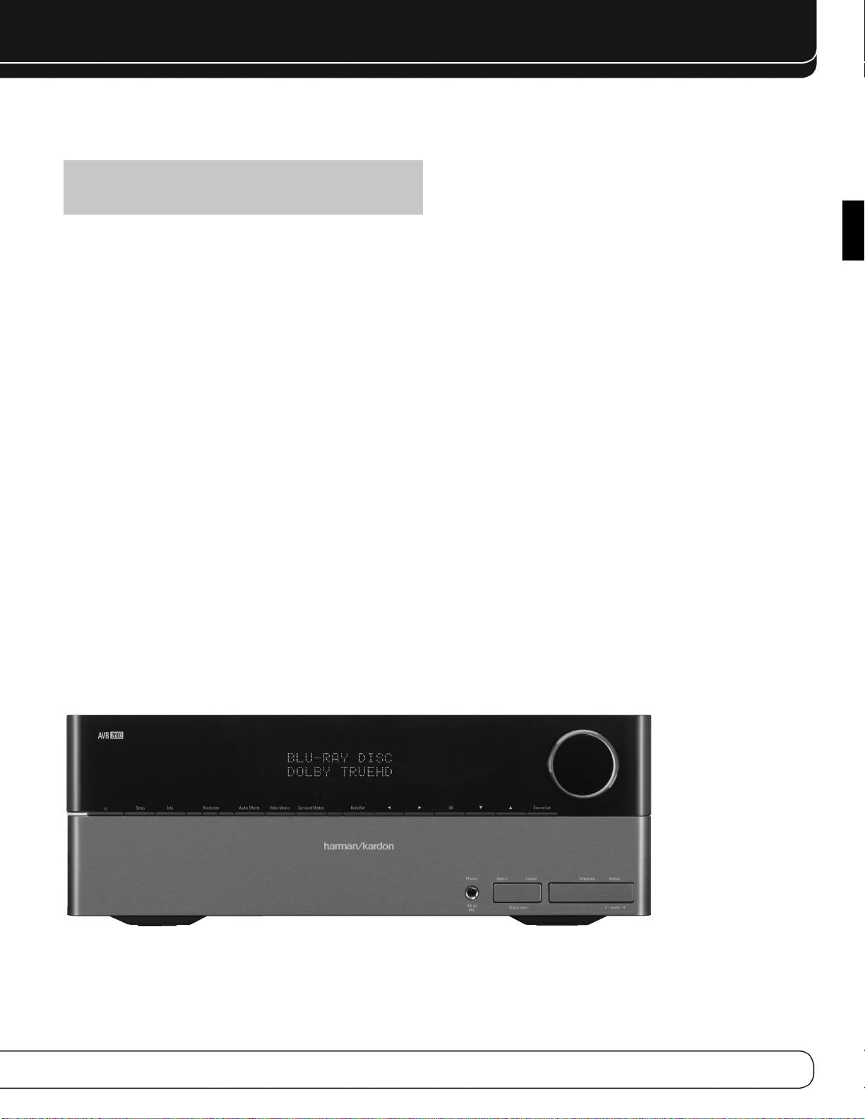
INTRODUCTION
Veuillez enregistrer votre AVR 2600 à
l’adresse : www.harmankardon.com
REMARQUE : Il vous faudra indiquer le numéro de série du produit. Au
même moment, vous pourrez choisir d’être prévenu de l’existence de nouveaux produits et/ou de promotions spéciales.
Merci d’avoir choisi un produit Harman
®
Kardon
Depuis plus de cinquante ans, Harman Kardon®s’est donné pour mission de partager sa passion pour la musique et le divertissement, en s’appuyant sur une technologie de pointe pour des performances exceptionnelles. Harman Kardon, Inc. a
inventé le récepteur, composant unique conçu pour simplifier le divertissement à
domicile tout en offrant des performances sans compromis. Au fil des ans, les produits Harman Kardon sont devenus plus faciles à utiliser tout en offrant plus de
fonctionnalités et un son toujours meilleur. L’AVR 2600, récepteur audio/vidéo
numérique multizone à 7.1 canaux, perpétue cette tradition en affichant des fonctions de traitement audio et vidéo parmi les plus avancées et un large éventail
d’options d’écoute et de visualisation.
Pour profiter au maximum de votre nouveau récepteur, veuillez lire ce manuel et
consultez-le à mesure que vous vous familiarisez avec ses fonctions et son utilisation.
Pour toutes vos questions concernant ce produit, son installation ou son utilisation,
veuillez prendre contact avec votre revendeur Harman Kardon ou votre installateur,
ou alors rendez nous visite à l’adresse www.harmankardon.com.
!
Section audio du récepteur audio/vidéo à
7.1 canaux Harman Kardon AVR 2600
• 65 Watts x 7, sept canaux en service à pleine puissance sur 8 ohms,
20 Hz – 20 kHz, <0,07% THD, 455 watts au total
• Amplificateur à haute capacité en courant, bande passante audio ultra
large et faible contre-réaction négative
• Circuits d’amplification à composants discrets
• Gestion des graves à quadruple séparation
®
• Deux processeurs Cirrus Logic
• Conversion A/N et N/A 192 kHz/24 bits
• Conversion ascendante avec échantillonnage à 96 kHz
®
• Traitement Dolby
Volume
à 32 bits
Modes Surround
• Dolby Digital EX, Dolby Digital Plus, Dolby TrueHD
®
• Dolby Pro Logic
• Harman Virtual Speaker
• Harman Headphone
• DTS-HD High Resolution Audio
• DTS®(5.1, DTS stéréo, DTS-ES®6.1 Discrete et Matrix)
• DTS 96/24
• DTS Neo:6
jusqu’à 96 kHz
®
• Logic 7
• Stéréo à 5 ou 7 canaux jusqu’à 96 kHz
• Surround Désactivé (shuntage DSP ou analogique)
II et IIx (film, musique et jeu) jusqu’à 96 kHz
™
, DTS-HD Master Audio
™
(DTS stéréo)
®
(film à 5, 6 ou 7 canaux ; musique à 5, 6 ou 7 canaux)
(film, musique et jeu) jusqu’à 96 kHz
™
FRANÇAIS
5
Page 68

INTRODUCTION
Entrées audio
• Entrée syntoniseur AM/FM/SIRIUS®*
• Entrées audio analogiques 1 à 5
• Entrée audio analogique en façade
• Entrée audio analogique à 6/8 canaux
Entrées audio/vidéo
• Trois entrées vidéo composite
• Entrée vidéo composite en façade
• Deux entrées vidéo en composantes à 100 MHz
™
• Quatre entrées HDMI
• Traitement vidéo Faroudja DCDi Cinema
il transcode le format vidéo composite 480i à vidéo en composantes, avec
interpolation jusqu’à 1080i
il transcode le format vidéo 480i à sortie HDMI, avec interpolation jusqu’à
1080p
• Connectivité d’accueil pour iPod** et iPhone avec reproduction
audio/vidéo
(v.1.3a avec Deep Color)
™
Entrées audio numériques
• Deux entrées coaxiales sur le panneau arrière / une entrée coaxiale en façade
• Deux entrées optiques sur le panneau arrière / une entrée optique en façade
Sorties
• Sorties Subwoofer
• Sorties audio analogiques 2 et 4
• Vidéo composite 2
• Sortie écran vidéo (composite et en composantes)
• Sorties audio numériques (une coaxiale)
• Sorties HDMI (v.1.3a avec Deep Color)
• Une sortie audio multizone à niveau enceinte et deux sorties audio multizone à
niveau de signal ligne (une dédiée et l’autre partagée avec les canaux arrière
Surround)
• Sortie casque d’écoute
Facilité d’utilisation
• Configuration automatisée EzSet/EQ™(microphone fourni)
• Interface utilisateur tout en couleur et menu de configuration générés en vidéo à
haute définition
• Afficheur en façade à matrice de points sur deux lignes
• Raccordements à code de couleurs
• Télécommande principale programmable pour sept périphériques (y compris la
commande de l’AVR par The Bridge III)
• Changement de nom des entrées sources
• Synchronisation labiale réglable (jusqu’à 180 ms)
• Port USB pour mises à jour du système
• Sortie d’alimentation d’accessoires commandée
• Sortie et entrée à infrarouges (IR) déportées
• Entrée IR Zone 2, Sortie Porteuse IR et A-BUS IR sortie
Accessoires fournis
Les accessoires suivants sont fournis avec l’AVR 2600.
Si l’un de ces accessoires manque, veuillez contacter le service clientèle de
Harman Kardon à l’adresse www.harmankardon.com.
• Télécommandes du système
• Microphone EzSet/EQ
• Antenne cadre AM
• Antenne filaire FM
• Quatre piles AAA
• Deux façades pour les jacks avant
* Syntoniseur radio satellite SIRIUS et souscription au service SIRIUS exigés. Le
matériel et le service sont vendus séparément. Le service SIRIUS n’est pas disponible en Alaska et à Hawaii.
** Recharge l’iPod nano de quatrième génération, l’iPod touch de deuxième géné-
ration, l’iPhone 3G, l’iPod nano de troisième génération, l’iPod classic, l’iPhone,
l’iPod touch de première génération, l’iPod nano de deuxième génération, l’iPod
de cinquième génération, l’iPod nano de première génération, l’iPod de quatrième génération, l’iPod mini.
Bridge III dock, iPod et iPhone non inclus.
6
Page 69

Résolution Navigation
Modes
vidéo
Liste de
sources
Précédent/Quitter
OK
Navigation
Prise pour
casque
d'écoute /
microphone
EzSet/EQ
Entrées
audio
numériques
(optique et coaxiale
en façade)
Port
USB
Entrées
vidéo en
façade
Entrées audio analogique
en façade
Modes
Surround
Effets
audio
Configuration
Interrupteur
Veille/Allumé
Paramètres
d’informations
Volume
Afficheur de messages
Voyant
d'alimentation
/
/
Capteur IR de
la télécommande
COMMANDES EN FAÇADE
FRANÇAIS
REMARQUE : Pour faciliter le suivi des instructions faisant référence à cette illustration dans le manuel, une copie de cette page peut être téléchargée dans la section Assistance produit à l’adresse
www.harmankardon.com.
7
Page 70

COMMANDES EN FAÇADE
Voyant d'alimentation : Ce voyant DEL possède trois modes pos-
sibles :
• Alimentation principale coupée : Quand l’AVR est
débranché ou l’interrupteur d'alimentation principal est coupé, ce voyant DEL
est éteint.
• Veille : Le voyant DEL est orange et il indique que l’AVR est prêt à être
allumé.
• Allumé : Quand l’AVR est allumé, ce voyant DEL devient blanc.
REMARQUE : Le message « PROTECT » s’affiche, éteignez l’AVR et
débranchez-le. Vérifiez si les câbles des enceintes ne sont pas en court-circuit. Si ce n’est pas le cas, apportez l’appareil à un centre de service autorisé
Harman Kardon pour son inspection et réparation avant de l’utiliser à nouveau.
Interrupteur Veille/Allumé : Cet interrupteur électrique allume le
récepteur ou le met en mode Veille pour une mise en service rapide.
Bouton d’Installation : Appuyez sur ce bouton pour avoir accès au
menu principal de l’AVR.
Touche Paramètres d’informations : Appuyez sur cette
touche pour accéder directement au sous-menu Informations des sources de l’AVR
qui présente les paramètres de la source actuelle.
Résolution : Appuyez sur cette touche pour accéder au paramètre de réso-
lution de la sortie vidéo de l’AVR : 480i, 480p, 720p, 1080i ou 1080p.
(si disponible sur la source et à l’affichage).
NOTE IMPORTANTE : Si la résolution de la sortie vidéo de l’AVR est
supérieure aux capacités de la connexion actuelle, vous ne verrez pas d’image. Si la meilleure connexion vidéo disponible de l’AVR vers le téléviseur est
composite, appuyez sur cette touche et changez la résolution à 480i.
Prise pour casque d'écoute : Branchez une fiche stéréo de
casque d’écoute de 1/4" dans cette prise pour une écoute plus intime. Cette prise
sert à brancher le microphone fourni destiné à la procédure EzSet/EQ décrite dans
la section Configuration initiale.
Port USB : Ce port peut être utilisé en cas où une mise à jour pour le
récepteur soit disponible ultérieurement. Ne pas brancher un appareil à mémoire,
un produit périphérique ou un PC ici, à moins d’indication contraire pour un procédé de mise à jour.
Entrées audio numérique, vidéo et audio
analogique en façade :
utilisé temporairement, comme un appareil photo numérique ou une console de
jeux, sur ces prises. Utilisez uniquement un type de connexion audio et un type de
connexion vidéo.
REMARQUE : Dans les menus de l’AVR, ces prises sont appelées entrées
Optique avant, Coaxiale avant, Composite avant et Analogique avant.
Branchez un composant source qui est
Bouton de volume : Tournez ce bouton pour augmenter ou diminuer
le volume.
Afficheur de messages : Plusieurs messages s’affichent sur cet
afficheur sur deux lignes en réponse aux commandes et aux modifications du
signal d’entrée. En utilisation normale, le nom de la source actuelle s’affiche sur la
ligne supérieure et le mode Surround s’affiche sur la ligne inférieure. Lorsque le
système de menus affichés à l’écran (OSD) est utilisé, les paramètres du menu
courant s’affichent.
Capteur IR de la télécommande : Ce capteur reçoit des
ordres de commande à infrarouge (IR) générés par la télécommande. Il est important de vérifier qu’il n’est pas caché. S’il est impossible d’éviter de cacher le capteur, utilisez un récepteur en option Harman Kardon HE 1000 ou un autre récepteur à infrarouge et branchez-le sur l’entrée à infrarouge déportée situé sur le panneau arrière de l’AVR 2600
Effets audio : Appuyez sur cette touche pour accéder directement au
sous-menu Effets audio qui permet le réglage de la tonalité ainsi qu’à d’autres
réglages audio. Voir la section Configuration initiale pour de plus amples informations.
Modes vidéo : Appuyez sur cette touche pour accéder directement au
sous-menu Modes vidéo qui contient des réglages permettant d’améliorer l’image,
si nécessaire, après avoir réglé les paramètres d’image au moyen de l’écran vidéo
ou du téléviseur.
Modes Surround : Appuyez sur cette touche pour sélectionner un
mode de son Surround (multicanaux, par exemple). Le menu Modes Surround s’affiche sur l’écran et la ligne de menu s’affiche sur l’afficheur en façade. Voir la section Fonctions évoluées pour de plus amples informations concernant les modes
Surround.
Liste de sources : Appuyez sur cette touche pour sélectionner un
périphérique source, composant d’où provient un signal de reproduction, un DVD
par exemple.
Précédent/Quitter : Appuyez sur cette touche pour revenir au menu
précédent ou pour quitter le système de menus.
1/57/3 Navigation : Ces touches sont utilisées pour naviguer dans
les menus de l’AVR, comprenant ceux du syntoniseur, du périphérique USB, de The
Bridge II, de la webradio et du réseau.
OK : Appuyez sur cette touche pour sélectionner l’élément mis en évidence.
8
Page 71

Cordon d’alimentation
secteur
Entrées analogiques 1 à 5
Entrées à 6/8 canaux
Entrée
Composantes
1,2 et 3
Entrée
IR déportée
Entrée
IR Zone 2
Syntoniseur
SIRIUS
The Bridge III
Sortie
IR déportée
Sorties
enceinte
centrale
Sortie secteur
accessoires
commandée
Interrupteur
d'alimentation
principal
Entrée
Composantes
1 et 2
Sorties enceintes
Surround
arrière/Zone 2
Sorties
enceintes
frontales
Antenna FM
Sorties analogiques 2 et 4
Sorties
enceintes
Surround
Sorties écran vidéo
en composantes
Sortie
vidéo 2
Sortie
Subwoofer
Sortie
audio
numérique
coaxiale
Entrée Audio numérique
coaxiale 1 et 2
Entrée
audio
numérique
optique
Grille du ventilateur
Sorties écran
vidéo
HDMI 1, 2, 3 et 4
Antenna AM
Sortie écran
HDMI
CONNEXIONS DU PANNEAU ARRIÈRE
FRANÇAIS
REMARQUE : Pour faciliter le suivi des instructions faisant référence à cette illustration dans le manuel, une copie de cette page peut être téléchargée dans la section Assistance produit à l’adresse
www.harmankardon.com.
9
Page 72

CONNEXIONS DU PANNEAU ARRIÈRE
Interrupteur de courant électrique : Cet interrupteur
mécanique met en route ou arrête l’alimentation électrique. Il est généralement
laissé allumé, et ne peut être mis en route ou arrêté à partir de la télécommande.
Entrées à 6/8 canaux : Raccordez les sorties audio analogiques
multicanaux d’un lecteur non HDMI (DVD-audio, SACD
ou tout autre décodeur externe) à ces prises.
™
, Blu-ray Disc™ou DVD-HD,
Entrées audio numériques coaxiales 1/2 et
optiques 1/2 :
compatible et si vous n’utilisez pas de connexion HDMI pour l’audio de ce périphérique, branchez-la à l’une de ces prises pour écouter les formats audio numériques, comme Dolby Digital, DTS et MIC linéaire. N’utilisez qu’un seul type de
connexion audio numérique pour chaque source.
Si une source est dotée d’une sortie audio numérique
Sorties audio numériques coaxiales et optiques :
Si une source est également un enregistreur audio, branchez l’une des sorties
audio numériques à l’entrée correspondante de l’enregistreur pour une meilleure
qualité d’enregistrement. Seuls les signaux audio numériques MIC sont disponibles
pour l’enregistrement. Les deux signaux audio numériques, coaxial et optique, sont
disponibles sur chaque sortie audio numérique.
Jack du Syntoniseur SIRIUS : Connectez ici un syntoniseur
radio satellite SIRIUS.
Entrée à infrarouge (IR) Zone 2 : Branchez un récepteur IR
déporté situé dans la zone distante d’un système multizone à cette prise pour
commander l’AVR (ainsi que tout périphérique source connecté à la sortie IR
déportée) depuis la zone distante.
Sortie et entrée à infrarouge (IR) : Si le récepteur IR
déporté en façade est caché, connectez un récepteur à infrarouge en option à la
prise Entrée IR déportée. La sortie IR déportée peut être raccordée à l’entrée IR
déportée d’un produit compatible pour en permettre la télécommande par l’AVR.
Entrées et sortie HDMI : Le HDMI (High-Definition Multimedia
Interface - interface multimédia haute définition) est une connexion destinée à
transmettre des signaux audio et vidéo numériques entre deux appareils.
Raccordez jusqu’à quatre périphériques sources HDMI aux entrées HDMI au
moyen d’une connexion à seul câble.
Si vous connectez la sortie HDMI à votre écran vidéo, l’AVR 2600 transcode automatiquement les signaux vidéo analogiques au format HDMI, avec interpolation
jusqu’à 1080p.
REMARQUES : Si vous raccordez un écran DVI à l’une des sorties HDMI :
• utilisez un adaptateur HDMI/DVI ;
• vérifiez que l’écran soit compatible HDCP. S’il ne l’est pas, ne le raccordez
pas à une sortie HDMI ; utilisez plutôt une connexion vidéo analogique ;
• réalisez toujours une connexion audio séparée.
Entrées analogiques 1 à 5 : Raccordez les sorties audio analo-
giques gauche et droite d’un périphérique source à l’une de ces entrées. Ces
entrées peuvent être appariées avec n’importe quelle entrée vidéo.
REMARQUES :
• chacune des entrées analogiques 2 et 4 est associée avec un groupe de
sorties. Utilisez ces connecteurs pour un enregistreur audio ou vidéo ;
• vous pouvez aussi raccordez une source à une entrée audio analogique et
numérique simultanément. Cela est utile lors d’enregistrements, d’application multizone ou tout simplement en tant que connexion de réserve.
Sorties analogiques 2 et 4 : Raccordez l’une de ces sorties
audio analogiques aux entrées audio analogiques d’un périphérique d’enregistrement. Ces sorties délivrent un signal quand une source audio analogique est
reproduite.
Sorties Subwoofer : Si vous disposez d’un subwoofer alimenté doté
d’une entrée à niveau de signal ligne, raccordez-la à la sortie Subwoofer.
Entrée The Bridge III : Connectez une station d’accueil Harman
Kardon (non compris) à cette entrée pour une utilisation avec la plupart des modèles de stations d’accueil pour iPod, de type 4G et versions ultérieures, iPhone ou iPhone 3G (non compris). Eteignez le récepteur (mode Standby)
lors de la connexion de The Bridge III.
Grille du ventilateur : Cette zone couvre la grille du ventilateur de
l’AVR 2600 pour refroidir le système. Respectez une distance d’au moins 7,5 cm
depuis la surface la plus proche pour éviter la surchauffe de l’appareil. Il est normal que le ventilateur reste éteint à la plupart des niveaux de volume. Un capteur
de température allume automatiquement le ventilateur lorsque cela est nécessaire
uniquement.
NOTE IMPORTANTE : N’obstruez jamais la grille du ventilateur car cela
pourrait entraîner la surchauffe de l’AVR jusqu’à des niveaux dangereux.
Entrées vidéo 1, 2 et 3 : Utilisez ces prises pour raccorder vos
composants sources vidéo (magnétoscope, lecteur DVD ou récepteur réseau câblé)
au récepteur. N’utilisez qu’un seul type de connexion vidéo pour chaque source.
Sorties vidéo 2 : Connectez l’une de ces sorties vidéo analogique aux
entrées vidéo composite ou S-vidéo d’un périphérique d’enregistrement. Ces sorties délivrent un signal quand une source audio analogique est reproduite.
Sortie Ecran Vidéo : Si l’une de vos sources utilise des connexions
vidéo composite, connectez cette sortie écran à l’entrée correspondante de votre
affichage vidéo. Si votre affichage vidéo est équipé d’entrées HDMI ou composant
vidéo, cette connexion n’est pas nécessaire, puisque l’AVR 2600 convertira le
signal source vidéo composite au bon format pour une connexion câblée simple à
un téléviseur.
Entrées Composant Vidéo 1/2 : Si une source vidéo peut
fournir un signal vidéo analogique en composantes (Y/Pb/Pr) et si vous n’utilisez
pas une connexion HDMI, connectez les sorties vidéo en composantes de la source
à l’un des groupes d’entrées vidéo en composantes. N’effectuez aucune autre
connexion vidéo à cette source.
10
Page 73

CONNEXIONS DU PANNEAU ARRIÈRE
Sorties écran vidéo en composantes : Si vous utilisez
l’une des entrées vidéo en composantes et si votre téléviseur ou écran vidéo est
équipé vidéo en composantes (mais pas HDMI), connectez ces prises à l’écran
vidéo.
REMARQUES :
• En raison des protections contre la copie, il n’y a pas de sortie écran vidéo
en composantes pour les sources protégées contre la copie.
• Les signaux vidéo composite sont interpolés jusqu’à 1080i et disponibles
sur ces sorties. Si la meilleure connexion de votre écran vidéo est vidéo en
composantes, c’est la seule connexion vidéo nécessaire entre l’AVR et
l’écran.
Prises antenne AM et FM : Branchez les antennes AM et FM
fournies sur leur prise respective pour recevoir la radio.
Sorties préamplifiées : Raccordez ces prises à un amplificateur
externe si vous souhaitez plus de puissance. Les sorties préamplifiées Surround
arrière/Zone 2 peuvent être raccordées à un amplificateur externe pour alimenter
les enceintes de la zone distante d’un système multizone.
Port A-BUS : Utilisez un câble de catégorie 5/5e pour raccorder ce port à
un périphérique A-BUS en option pour une utilisation multizone. Si le système ABUS est utilisé, il est possible d’avoir un système complet à 7.1 canaux dans la
salle d’écoute principale tout en utilisant le système multizone.
Sorties enceintes frontales, centrale et
Surround :
chaque paire de bornes à l’enceinte appropriée. N’oubliez pas de respecter la
polarité (connexions positives et négatives).
Sorties enceintes Surround arrière/Zone 2 : Ces
sorties enceintes sont destinées aux canaux Surround arrière d’un système de
cinéma à domicile à 7.1 canaux ou peuvent être réaffectées à la salle distante lors
d’une utilisation multizone.
Sortie secteur accessoires commandée : Vous pou-
vez brancher le cordon d’alimentation secteur d’un périphérique source sur cette
sortie pour l’allumer lorsque vous allumez le récepteur. N’utilisez pas de source
consommant plus de 50 watts.
Entrée alimentation secteur : Après avoir réalisé toutes les
autres connexions, raccordez le cordon d’alimentation secteur à une prise de courant murale non commandée.
Utilisez un câble d’enceinte à deux conducteurs pour raccorder
FRANÇAIS
11
Page 74

FONCTIONS PRINCIPALES DE LA TÉLÉCOMMANDE
Arrêt AVR
Marche AVR
Touches de sélection de source
Effets audio
Touches Alphanumériques
Touches programmables
Volume
Sourdine
Marche périphériques
Arrêt périphériques
Modes Surround
Modes vidéo
OK
Navigation
Activité
Menu
Menu disque
Chaîne
Paramètres de mise en veille
Touches de commandes de lecture
Lentille de l’émetteur à infrarouge
Dernier
Précédent/Quitter
Enregistrement
Paramètres d’informations
Configuration
Commutateur de sélection de zone
12
SETUP
INFO SLEEP
REMARQUE : Pour faciliter le suivi des instructions fai-
sant référence à cette illustration dans le manuel, une copie de
cette page peut être téléchargée dans la section Assistance produit à l’adresse www.harmankardon.com.
Page 75

FONCTIONS PRINCIPALES DE LA TÉLÉCOMMANDE
La télécommande de l’AVR 2600 peut contrôler jusqu’à 8 appareils, dont l’AVR luimême et un iPod placé dans la station d’accueil incluse The Bridge III. Pendant le
processus d’installation, vous pourrez programmer les codes pour chaque composant source dans la télécommande. Pour faire fonctionner un composant, appuyez
sur le bouton de sélection correspondant afin de changer le mode d’appareil.
Chaque Sélecteur de Source a été préprogrammé pour contrôler certains types de
composants, les seuls éléments changeant étant les codes spécifiques à chaque
marque et modèle, en fonction du code produit qui est programmé. Les Sélecteurs
de Source AUX et Câble/SAT peuvent être utilisés pour de multiples types d’appareils, selon le premier chiffre du code produit. D’autres Sélecteurs de Source peuvent
être réassignés à d’autres types d’appareils (voir Section Installation initiale).
Touche de sélection de source AUX : Les codes pro-
duits des lecteurs CD commencent par 0, 1 ou 2. Les codes des magnétoscopes
commencent par 3 ou 4. Les codes des décodeurs HDTV commencent par 6, les
codes des lecteurs DVD portables commencent par 7 et les codes des décodeurs
®
TiVo
commencent par 8.
Sélection de source Cable/SAT : Les codes des décodeurs
câble commencent par 0, 1 ou 2, et les codes des décodeurs satellite commencent par 3 ou 4.
NOTE IMPORTANTE : Toutes les entrées audio et vidéo de l’AVR 2600
sont attribuées indépendamment. Sélectionnez les entrées auxquelles le périphérique est raccordé physiquement pendant la Configuration initiale. Tous
les périphériques peuvent être connectés à n’importe quelle entrée compatible et n’importe quel nom peut lui être attribué (DVD ou Jeu).
La plupart des touches de la télécommande ont des fonctions dédiées, bien que
les codes précis émis varient en fonction du mode du périphérique.En raison du
vaste éventail de fonctions des nombreux périphériques sources, seules les fonctions les plus courantes ont été intégrées dans la télécommande : touches alphanumériques, touches de commandes de lecture, commande de chaînes de télévision, accès aux menus et Marche/Arrêt.
Les touches dédiées de l’AVR dont disponibles à tout moment, même dans un autre
mode périphérique : Marche/Arrêt de l’AVR, Effets audio, Modes vidéo, Modes
Surround, Volume, Sourdine et Paramètres de mise en veille. Appuyez sur la touche
Paramètres de l’AVR en bas de la télécommande pour revenir en mode AVR.
La fonction d’une touche varie en fonction du composant qui est commandé.
Consultez le Tableau A13 de l’annexe qui énumère les fonctions de chaque type de
composant.
Lentille de l’émetteur à infrarouge : Lors des pressions sur
les touches de la télécommande, des codes infrarouges sont émis par cette lentille.
Touche Marche AVR : Appuyez sur cette touche pour allumer l’AVR.
L’interrupteur d'alimentation principal situé derrière le capot en façade doit être
allumé.
Touche Arrêt périphérique : Appuyez sur la touche de sélection
de source d’un périphérique, puis appuyez sur cette touche pour éteindre le périphérique.
Touche Marche périphérique : Appuyez sur la touche de
sélection de source d’un périphérique, puis appuyez sur cette touche pour allumer
le périphérique.
Touche Sourdine : Appuyez sur cette touche pour interrompre tempo-
rairement le son des sorties enceintes et casque d’écoute de l’AVR 2600. Pour
mettre fin à la sourdine, appuyez à nouveau sur cette touche, réglez le volume ou
éteignez le récepteur.
Touche Arrêt AVR : Appuyez sur cette touche pour éteindre l’AVR.
Touches de sélection de sources : Appuyez sur l’une de
ces touches pour sélectionner un périphérique source : DVD, CD, réseau câblé,
récepteur satellite ou HDTV. Une pression sur la touche allume également le récepteur et commute la télécommande en mode périphérique pour utiliser cette source. La première pression sur la touche de sélection Radio fait passer l’AVR sur la
bande de fréquences utilisée précédemment du syntoniseur (AM, FM ou SIRIUS).
Chaque pression successive change de bande.
Alors que le Sélecteur de Source DVD peut être utilisé pour faire fonctionner soit
un lecteur de disques Blu-ray Harman Kardon soit un lecteur de DVD Harman
Kardon, le mode par défaut est de commander un lecteur de disques Blu-ray
Harman Kardon. Pour basculer du mode lecteur de disques Blu-ray Harman Kardon
au mode lecteur de DVD, appuyez et maintenez enfoncé le Sélecteur de Source
DVD pendant 2 secondes. Le sélecteur de source flashera deux fois pour confirmer
que le mode de la télécommande a été modifié pour faire fonctionner l’autre type
de lecteur de disques.
Effets audio : Appuyez sur cette touche pour accéder directement au
sous-menu Effets audio qui permet le réglage de la tonalité de l’AVR ainsi qu’à
d’autres réglages audio. Voir la section Configuration initiale pour de plus amples
informations.
Modes vidéo : Appuyez sur cette touche pour accéder directement au
sous-menu Modes vidéo qui contient les paramètres d’image à utiliser après avoir
réglé les paramètres d’image de l’écran vidéo ou du téléviseur. Voir la section
Fonctions évoluées pour de plus amples informations.
Modes Surround : Appuyez pour accéder directement au menu des
Modes Surround. Sélectionnez une catégorie de mode Surround : Auto Select,
Virtual Surround, Stéréo, Film, Musique ou Jeu Vidéo. Le mode surround change
lorsque la ligne de menu est surlignée.
Pour changer le mode surround de la catégorie sélectionnée, appuyez sur la
Touche OK lorsque la ligne de menu est surlignée et sélectionnez l’une des options
de mode surround disponibles en utilisant les Touches 5/1 . Appuyez sur OK, ou
sur la Touche Retour/Quitter pour quitter le menu des Modes Surround et afficher
le menu supérieur suivant dans la hiérarchie.
Voir la section Fonctions évoluées pour de plus amples informations concernant
les modes Surround.
Touche Paramètres de mise en veille : Appuyez sur
cette touche pour activer le minuteur de mise en veille, qui éteint le récepteur
après une durée programmée allant jusqu'à 90 minutes. Chaque pression diminue
la durée de 10 minutes, et la dernière pression affiche le message « Mise en veille
désactivée ».
Commandes de volume : Une pression sur cette touche aug-
mente ou diminue le volume.
Touches de Navigation
mettent de faire des sélections dans le système de menus et d’utiliser le syntoniseur.
(
1/57/3
)
et OK : Ces touches per-
Touches Alphanumériques : Utilisez ces touches pour saisir
des nombres correspondant aux fréquences ou des canaux des stations de radio,
ou pour choisir les stations présélectionnés.
Dernière chaîne : Si vous faites fonctionner un décodeur câble, satelli-
te ou HDTV, appuyez sur ce bouton pour retourner à la dernière chaîne.
Activité : Avec cette touche, 11 activités au maximum peuvent être pro-
grammées pour émettre une série d’ordres de commande par une seule pression.
Exécutez une activité en appuyant sur cette touche puis la touche alphanumérique
(ou les touches Marche AVR ou Arrêt AVR) avec laquelle l’activité a été programmée (voir la section Fonctions évoluées pour de plus amples informations sur les
activités).
Précédent/Quitter : Appuyez sur cette touche pour revenir au menu
précédent ou pour quitter le système de menus.
FRANÇAIS
13
Page 76

FONCTIONS PRINCIPALES DE LA TÉLÉCOMMANDE
Touche Menu : Cette touche est utilisée dans le menu « lecture en
cours » du syntoniseur (y compris la Radio SIRIUS) et de The Bridge III, ainsi que
pour afficher le menu principal de certains appareils sources. Pour afficher le
menu principal de l’AVR 2600, appuyez sur le bouton d’installation.
Menu disque : Lors de la reproduction d’un DVD, appuyez sur la touche
de sélection de source DVD puis sur cette touche pour afficher le menu disque.
Touches multifonctions : Ces touches sont utilisées avec cer-
tains appareils sources. Voir le tableau A13 de l’annexe pour plus de détails. Elles
sont également utilisées avec un téléviseur équipé du Teletext si votre fournisseur
de télévision câblée ou satellite offre le service Teletext.
Commande des Chaînes / Pages : Une fois le syntoniseur
sélectionné, ce contrôle sélectionne une station de radio préréglée. Si vous faites
fonctionner un décodeur câble, satellite ou HDTV, appuyez sur ces boutons pour
changer de chaîne.
Bouton enregistrement : Appuyez sur cette touche pour réaliser
des enregistrements lorsqu’un enregistreur audio ou vidéo est utilisé.
Bouton d’installation : Appuyez pour afficher le Menu principal de
l’AVR, ou pour passer la télécommande en mode appareil AVR.
Touche Paramètres d’informations : Appuyez sur cette
touche pour afficher le menu d’informations de l’AVR qui contient les paramètres
de la source actuelle.
Commutateur de sélection de zone : Utilisez cette
touche pour déterminer si les commandes de l’AVR affectent la zone d’écoute
principale (Zone 1) ou la zone distante d’un système multizone (Zone 2). Pour une
utilisation normale, laisser le commutateur dans la position Zone 1.
Passer Piste : Ces touches sont utilisées avec des composants sources
pour changer de piste ou de chapitre.
Touches de commandes de lecture : Ces touches per-
mettent de commander la reproduction de la source ou The Bridge III.
14
Page 77

INTRODUCTION AU CINÉMA À DOMICICLE
Ce préambule est destiné à vous familiariser avec quelques concepts de base spécifiques aux récepteurs multicanaux à son Surround qui vous en faciliterons la
configuration et l’utilisation.
Système de cinéma à domicile courant
Un système de cinéma à domicile comprend généralement un récepteur
audio/vidéo qui commande le système, un lecteur de disques, un composant source pour les émissions de télévision (un récepteur réseau câblé, un récepteur satellite, un récepteur HDTV ou une antenne connectés au téléviseur), un écran vidéo
(téléviseur) et des enceintes.
Audio multicanaux
L’avantage principal d’un système de cinéma à domicile est la disposition d’enceintes tout autour de la salle pour produire le « son Surround ». Le son Surround
vous plonge dans la présentation pour un réalisme accru.
L’ AV R 2600 peut alimenter directement jusqu’à sept enceintes (plus subwoofer).
Chaque enceinte principale est alimentée par son propre canal amplificateur logé
dans le récepteur. Un système de plus de deux enceintes est appelé système multicanaux.
Frontales gauche et droite – Les enceintes principales sont
•
utilisées comme dans un système à deux canaux. Dans de nombreux modes
Surround, ces enceintes sont secondaires et l’action principale, surtout les dialogues, sont déplacés vers l’enceinte centrale.
Centre – L’enceinte centrale est utilisée pour les dialogues dans les films
•
et les émissions de télévision, permettant aux dialogues de prendre naissance à
proximité du visage des acteurs pour un son plus naturel.
Surround gauche et droite – Les enceintes Surround amélio-
•
re la directionnalité des sons ambiants. En outre, les bandes sonores dynamiques sont réparties sur plusieurs enceintes pour éviter le risque de surcharge
de chaque enceinte.
Surround Arrière gauche et droite – Enceintes Surround
•
complémentaires pouvant être placées derrière la position d’écoute pour améliorer la précision des sons ambiants et offrir des panoramiques plus réalistes.
Les enceintes Surround Arrière sont utilisées dans les modes Surround destinés
aux systèmes à 7.1 canaux, tels que Dolby Digital EX, Dolby Digital Plus, Dolby
TrueHD, DTS-ES (Discrete et Matrix), DTS-HD High Resolution Audio, DTS-HD
Master Audio et Logic 7 (modes 7.1). Les enceintes Surround Arrière sont facultatives et l’AVR 2600 peut être configuré pour un système à 5.1 canaux dans la
zone d’écoute principale et les canaux Surround Arrière sont alors réaffectés à
un système multizone, dans lequel les canaux Surround Arrière alimentent des
enceintes situées dans une autre salle. La plupart des auditeurs exigent que les
enceintes Surround soient aussi puissantes que les enceintes frontales.
Bien que toutes les enceintes du système soient réglées pour délivrer une puissance sonore équivalente dans la position d’écoute, la plupart des artistes utilisent les enceintes Surround uniquement pour les effets d’ambiance et ils programment leur équipement pour envoyer très peu de son à ces enceintes.
• Subwoofer – Un subwoofer est destiné à reproduire uniquement les
plus basses fréquences (les graves). Il complète les enceintes satellites, de
dimensions et de gamme plus réduites, utilisées pour les autres canaux. De
nombreux programmes au format numérique, comme les films enregistrés en
Dolby Digital, contiennent un canal LFE (low-frequency effects) qui est dirigé
vers le subwoofer. Le canal LFE reproduit le grondement d’un train ou d’un
avion, ou la puissance d’une explosion, pour accroître le réalisme et l’émotion
de votre système de cinéma à domicile. Certains utilisent deux subwoofers pour
augmenter la puissance et améliorer la distribution du son.
Modes Surround
Il existe deux théories différentes quant à la reproduction du son Surround et à la
distribution des informations aux enceintes. De nombreux algorithmes ont été
développés pour essayer de reproduire les sons que nous entendons en situation
réelle et ont débouché sur une vaste gamme d’options.
Plusieurs compagnies ont développé le son Surround de différentes manières :
Dolby Laboratories – Dolby TrueHD, Dolby Digital Plus, Dolby
•
Digital, Dolby Digital EX, Dolby Pro Logic II et IIx.
DTS – DTS-HD High Resolution Audio, DTS-HD Master Audio, DTS, DTS-ES
•
(Discrete et Matrix), DTS Neo:6, DTS 96/24
Harman International
•
(la société mère de Harman Kardon) –
parleur Harman Virtual, Casque Harman
Modes stéréo – Modes génériques qui vont du mode stéréo conven-
•
tionnel à deux canaux aux modes stéréo à 5 canaux voire 7 canaux
Le Tableau A13 de l’annexe présente des explications détaillées des groupes de
modes et des options des modes disponibles dans chaque groupe. Les modes
numériques, tels que Dolby Digital et DTS, sont uniquement disponibles avec des
programmes encodés spécifiquement, tels que HDTV, Blu-ray Disc et la télévision
numérique par câble ou satellite. D’autres modes peuvent être utilisés avec des
signaux numériques ou analogiques pour créer une présentation Surround différente ou pour utiliser un nombre différent d’enceintes. Le choix du mode Surround
dépend du nombre d’enceintes de votre système, des contenus que vous regardez
ou écoutez et de vos goûts personnels.
Logic 7, Haut-
FRANÇAIS
15
Page 78
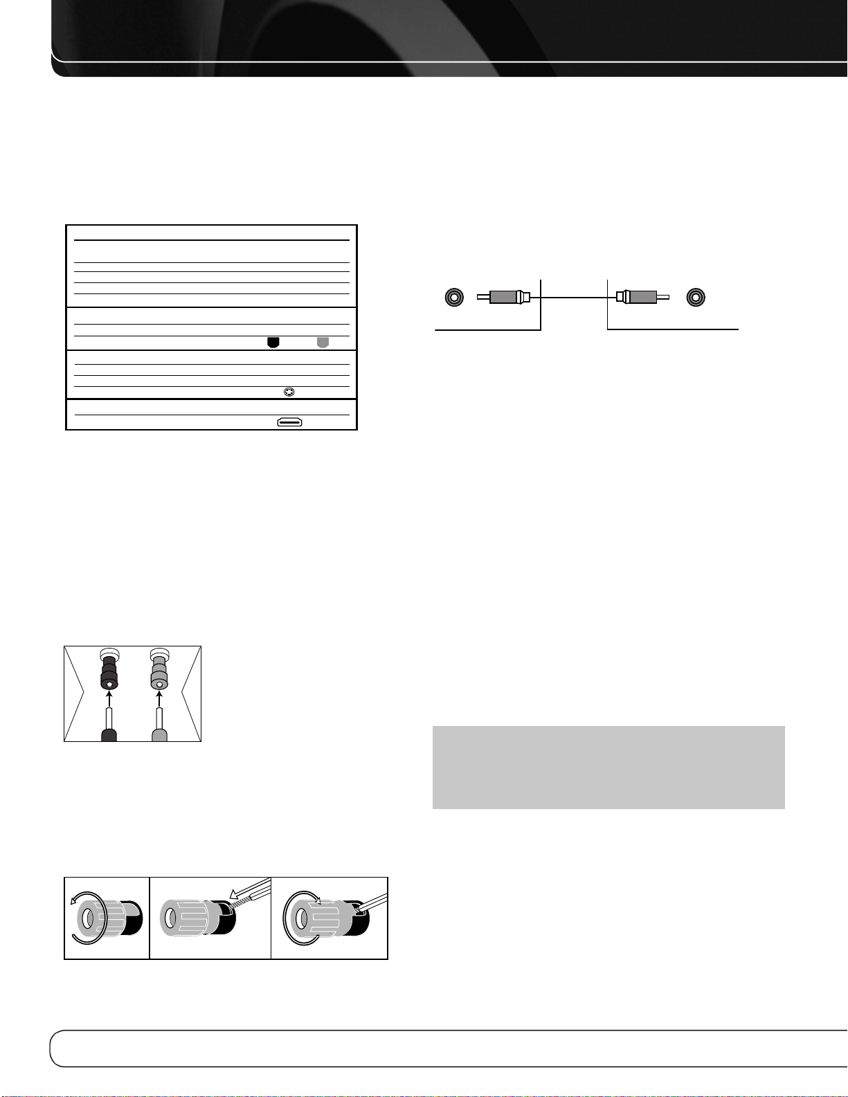
CONNECTIONS
Subwoofer
Sortie
préamplifiée
12 3
Différents types de connexions audio et vidéo sont utilisées pour raccorder le
récepteur, les enceintes, l’écran vidéo et les périphériques sources. L'association
d'industries CEA
®
(Consumer Electronics Association) a établi un code de couleurs
(voir le Tableau 1).
Tableau 1 – Guide des couleurs des
connexions
Connexions audio
Gauche Droite
Frontales (FL/FR)
Centrale (C)
Surround (SL/SR)
Surround Arrière (SBL/SBR)
Subwoofer (SUB)
Connexions audio numériques
Coaxiale
Optique
Connexions vidéo
En composantes Y Pb Pr
Composite
S-Video
Connexions HDMI™ (audio/vidéo numériques)
HDMI
Blanc
Bleu Gris
Brun clair
Marron
Entrée Sortie
Vert Bleu Rouge
Vert
Violet
Orange
Jaune
Rouge
Connexions des enceintes
Les câbles d’enceintes transportent un signal amplifié des bornes d’enceintes du
récepteur jusqu’à chaque enceinte. Ils comprennent deux fils conducteurs entourés d’une isolation en matière plastique qui est différenciée d’une certaine manière, au moyen de couleurs ou de traits.
La différentiation garantit la polarité sans laquelle les performances dans les
graves peuvent être affectées. Chaque enceinte est raccordée aux bornes de sortie
enceintes du récepteur au moyen de deux conducteurs, un positif (+) et un négatif
(–). Branchez toujours la borne positive de l’enceinte, qui est généralement de
couleur rouge, à la borne positive du récepteur, qui porte la couleur indiquée dans
le Guide des couleurs des connexions ci-dessus (Tableau 1). Les bornes négatives
sont toutes noires.
L’ AV R 2600 utilise des bornes à vis pour
enceintes qui peuvent accueillir des fiches
bananes ou des câbles à conducteurs nus.
+
Les fiches bananes s’introduisent dans le trou
au centre du capuchon de borne (voir Figure 1).
Subwoofer
Le subwoofer est destiné à reproduire les basse fréquences (graves), qui exigent
plus de puissance. Pour obtenir de meilleurs résultats, la plupart des fabricants
d’enceintes proposent des subwoofers alimentés qui contiennent leur propre
amplificateur. En général, une connexion à niveau de signal ligne (non amplifiée)
est réalisée entre la sortie Subwoofer du récepteur et la prise correspondante sur
le subwoofer, comme illustré par la Figure 3.
Bien que les sorties subwoofer violettes ressemblent à des prises audio analogiques pleine gamme, elles sont filtrées pour délivrer uniquement les basses fréquences. Ne connectez ces sorties à aucun autre périphérique.
Figure 3 – Connexion Subwoofer
CONNEXION DES PÉRIPHÉRIQUES
SOURCE À L’AVR
Les signaux audio et vidéo proviennent des “appareils sources”, dont votre lecteur
de disques Blu-ray ou de DVD, lecteur CD, enregistreur numérique vidéo ou autre
enregistreur, lecteur de cassettes, console de jeux, décodeur câble ou satellite,
iPod ou iPhone installé dans la station d’accueil The Bridge III ou lecteur MP3. Le
syntoniseur de l’AVR compte également comme une source, bien qu’aucune
connexion externe autre que les antennes FM et AM et le syntoniseur SIRIUS ne
soit nécessaire.
Des connexions séparées sont nécessaires pour les parties audio et vidéo du
signal, sauf pour les connexions numériques HDMI. Les types de connexions utilisées dépendent des possibilités du périphérique source et de l’écran vidéo.
Connexions audio
Il y a deux types de connexions audio : numérique et analogique. Les signaux
audio numériques sont nécessaires pour écouter des sources encodées en modes
Surround numériques, tels que Dolby Digital et DTS, ou pour les signaux audio
numériques MIC non comprimés. Il existe trois types de connexions audio numériques : HDMI, coaxiales et optiques. N’utilisez qu’un type de connexion audio
numérique pour chaque périphérique source. Il est toutefois possible de réaliser
des connexions audio numériques et analogiques à partir de la même source.
Figure 1 – Bornes serre-fils pour enceintes avec fiches bananes
Les câbles à conducteurs nus sont raccordés comme suit (voir Figure 2) :
1. Dévissez le capuchon de borne jusqu’à ce que le trou débouchant soit découvert.
2. Introduisez l’extrémité dénudée du conducteur dans le trou.
3. Serrez le capuchon à la main jusqu’à ce que le conducteur soit bien serré.
Figure 2 – Bornes serre-fils pour enceintes avec conducteurs dénudés
16
REMARQUE :Les signaux HDMI peuvent véhiculer la partie audio et la
partie vidéo. Si votre périphérique d'affichage vidéo est pourvu d’une entrée
HDMI, réalisez une connexion HDMI unique entre chaque périphérique source
et l’AVR. Une connexion audio numérique séparée n’est généralement pas
nécessaire. Baissez totalement le volume de votre téléviseur.
Audio numérique
L’ AV R 2600 est équipé de quatre entrées et d’une sortie HDMI (High-Definition
Multimedia Interface - interface multimédia haute définition). La technologie HDMI
permet de véhiculer les informations audio et vidéo numériques au moyen d’un
seul câble, avec la meilleure qualité d’image et de son.
L’ AV R 2600 met en œuvre la technologie HDMI (v.1.3a avec Deep Color) et peut
traiter les composantes audio et vidéo des données HDMI pour réduire le nombre
de connexion câblées de votre système.L’AVR 2600 prend en charge la fonction
Deep Color qui améliore considérablement les nuances de couleurs pouvant être
affichées ainsi que les derniers formats audio multicanaux sans perte (lossless),
Dolby TrueHD et DTS-HD Master Audio entre autres.
Page 79
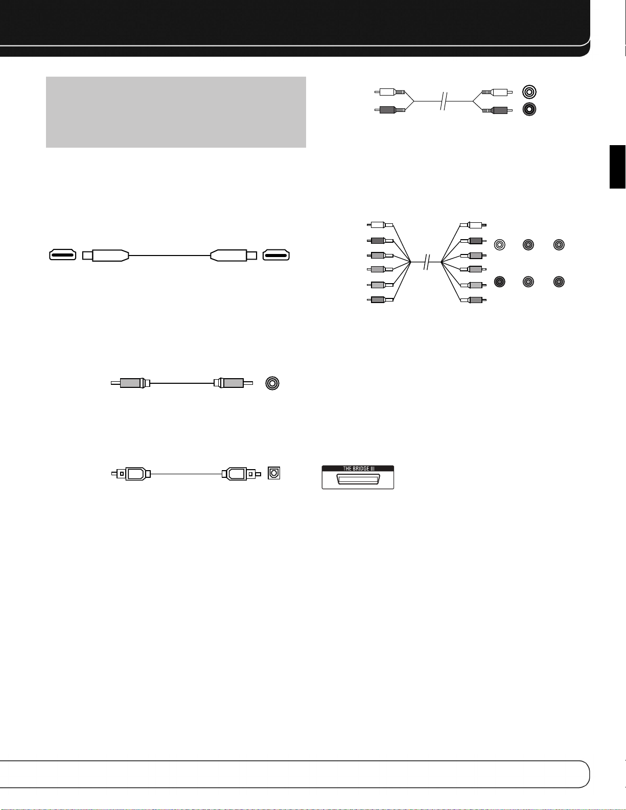
CONNECTIONS
Optique
Câble audio
numérique optique
REMARQUE : Certains lecteurs DVD-Audio, SACD, Blu-ray Disc et HD-DVD
délivrent uniquement des signaux audio multicanaux sur leur sorties analogiques multicanaux. Réalisez une connexion audio analogique séparée en
plus de la connexion HDMI qui est utilisée pour véhiculer les signaux vidéo et
pour écouter des contenus Dolby Digital, DTS ou MIC enregistrés sur le
disque.
L’ AV R 2600 convertit les signaux vidéo analogiques au format HDMI, y compris les
menus affichés à l’écran, avec interpolation jusqu’à la résolution à haute définition
1080p.
La forme du connecteur HDMI permet un branchement plus facile (voir Figure 4).
Si votre écran vidéo est doté d’une entrée DVI et qu’il est compatible HDCP, utilisez
un adaptateur HDMI/DVI (non fourni). Une connexion audio séparée est nécessaire.
La longueur du câble HDMI est limitée à 3 mètres environ.
Figure 4 – Connexion HDMI
Si votre écran vidéo ou périphérique source n’est pas équipé HDMI, utilisez une
des connexions vidéo analogiques (vidéo composite, S-vidéo ou vidéo en composantes) ainsi qu’une connexion audio séparée.
Les prises audio numériques coaxiales utilisent généralement le code de couleur
orange. Bien qu’elles ressemblent à des prises analogiques, il convient de ne pas
connecter des sorties audio numériques coaxiales à des entrées analogiques et
vice-versa (voir la Figure 5).
Câble audio
numérique coaxial
Figure 5 – Connexion audio numérique coaxiale
Les prises audio numériques optiques sont généralement couvertes d’un obtura-
teur pour les protéger de la poussière. Les prises d’entrée sont codées par couleur
avec un obturateur noir, tandis que les sorties utilisent un obturateur gris. Voir la
Figure 6.
Prise coaxiale
Câble audio
analogique (RCA)
Figure 7 – Connexion audio analogique
Les entrées 6/8 canaux sont des connexions analogiques multicanaux utilisées
avec des sources de haute définition qui décodent les contenus numériques protégés, tels que certains lecteurs de DVD-Audio, SACD, disques Blu-Ray et HD-DVD.
Voir Figure 8. La connexion audio analogique multicanaux n’est pas requise pour
les lecteurs compatibles avec HDMI version 1.1 ou supérieure, ou les signaux PCM
linéaires par le biais d’une connexion HDMI. Consultez le manuel d’utilisation de
votre lecteur de disques pour plus d’informations, et voir page 27.
Frontale Centrale
Câble audio
analogique
multicanaux
(RCA)
Figure 8 – Connexion audio analogique multicanaux
L’ AV R 2600 comporte également une connexion propriétaire, spécifique pour la
station d’accueil The Bridge III pour iPod ou iPhone. Si vous possédez un iPod pouvant être placé sur un dock (la plupart des modèles, 4G ou ultérieur), un iPhone ou
iPhone 3G, connectez The Bridge III (inclus) au port The Bridge III du récepteur. Voir
Figure 9. Placez votre iPod ou iPhone (non compris) dans le dock The Bridge III, et
vous pouvez écouter votre matériel audio par l’intermédiaire de votre système
audio de haute performance. Vous pouvez voir des images fixes ou du matériel
vidéo stockés sur un iPod capable de lire des photos ou vidéos et supportant la
navigation vidéo ou sur un iPhone. Utilisez la télécommande de l’AVR 2600 pour
commander l’iPod, grâce aux messages de navigation affichés en façade et un
affichage vidéo connecté à l’AVR. The Bridge III envoie le son analogique vers l’AVR
2600 et est disponible dans le système multizone
Blanc
Rouge Gris Violet
.
L
R
Surround
Bleu Vert
Subwoofer
FRANÇAIS
Figure 6 – Connection audio numérique optique
Audio analogique
Les connexions analogiques requièrent deux câbles, un pour le canal gauche
(blanc) et l’autre pour le canal droit (rouge). Les connexions analogiques requièrent
deux câbles, un pour le canal gauche (blanc) et l’autre pour le canal droit (rouge).
Ces deux câbles sont souvent jumelés (voir la Figure 7).
Pour les sources dotées de sorties audio numériques et analogiques, vous pouvez
réaliser les deux connexions.
La connexion audio analogique est nécessaire pour l’utilisation multizone car le
système multizone de l’AVR 2600 ne peut pas convertir un signal numérique au
format analogique. Utilisez les connections audio analogues avec les sorties d’enceintes Surround Arrière/Zone 2, en cas où une autre source digitale à deux
canaux est en utilisation dans la pièce d’écoute principale. L’A VR 2600 peut uniquement traiter une source MIC à la fois.
Vous ne pouvez enregistrer des contenus à partir d’un DVD ou d’autres sources
protégées contre la copie au moyen de connexions analogiques. Veillez à respecter
toutes les lois sur le droit d'auteur, si vous décidez de réaliser une copie pour votre
utilisation personnelle.
Figure 9 – Port The Bridge II
Connexions vidéo
De nombreuses sources délivrent des signaux audio et vidéo (lecteur Blu-ray Disc
ou DVD, récepteur réseau câblé, récepteur HDTV, récepteur satellite, magnétoscope, enregistreur vidéo numérique). En plus de la connexion audio, réalisez un type
de connexion vidéo pour chacune de ces sources (une seule pour chaque source).
Vidéo numérique
Si vous avez déjà connecté un périphérique source à l’une des entrées HDMI, vous
avez automatiquement réalisé une connexion vidéo car le signal HDMI incorpore
les composantes audio et vidéo numériques.
Vidéo analogique
Il existe deux sortes de connexions analogiques vidéo utilisées sur l’AVR 2600 :
vidéo composite et composant vidéo.
Vidéo composite est la connexion de base la plus courante. La prise est généralement jaune (code de couleur) et ressemble à une prise audio analogique. Ne branchez pas de câble vidéo composite dans une prise audio analogique ou numérique
coaxiale et vice-versa. Les composantes de chrominance (couleur) et de luminance (luminosité) du signal vidéo sont transmises au moyen d’un seul câble (voir la
Figure 10).
17
Page 80

CONNECTIONS
Câble vidéo en
composantes
Vert
Bleu
Rouge
Y
Pb
Pr
Câble vidéo
composite
Figure 10 – Connexion vidéo composite
La connexion vidéo « séparé », transmet les composantes de chrominance et de
luminance par des conducteurs différents unis dans un seul câble. Alignez correctement la fiche lorsque vous l’insérez dans la prise (voir la Figure 11).
Figure 11 – Connexion vidéo en composantes
Si votre écran vidéo en est équipé, il est recommandé d’utiliser la connexion HDMI
car elle constitue la connexion de meilleure qualité, suivie dans l’ordre décroissant
par vidéo en composantes et vidéo composite.
REMARQUES :
• Les sources protégées contre la copie ne sont pas disponibles aux sorties
écran vidéo en composantes.
• Les signaux vidéo analogiques à définition standard et à haute définition
peuvent être interpolés jusqu’à une résolution de 1080i pour les sorties
écran vidéo en composantes. Pour des performances vidéo optimales,
considérez l’acquisition d’un écran vidéo équipé HDMI avec une résolution
de 1080p.
PORT USB
Le Port USB de l’AVR 2600 est uniquement utilisé pour des mises à jour de logiciels. Si une mise à jour du système d’exploitation du récepteur est publiée à
l’avenir, elle pourra être téléchargée sur l’AVR au moyen de ce port. Des instructions complètes seront fournies en temps voulu.
ANTENNES
L’ AV R 2600 dispose de bornes différentes pour les antennes FM et AM fournies.
L’antenne FM se raccorde au connecteur de type F de 75 ohms (voir la Figure 12).
Figure 12 – Connexion antenne FM
L’antenne cadre AM doit être assemblée. Connectez les deux conducteurs aux
bornes à ressort du récepteur. Les conducteurs de l’antenne AM ne sont pas polarisés et vous pouvez les connecter à n’importe quelle borne (voir la Figure 13).
Figure 13 – Connexion antenne AM
Pour bénéficier de la radio satellite SIRIUS, achetez un syntoniseur SIRIUS-Ready
et souscrivez au service SIRIUS. Allez sur www.sirius.com pour obtenir des informations sur les modules syntoniseur SIRIUS-Ready. L’AVR 2600 est compatible
avec le syntoniseur SiriusConnect SC-H1, en utilisant le câble 8 broches DIN inclus
avec le module, et fournit l’alimentation requise par le syntoniseur. Il n’est donc
pas nécessaire d’utiliser l’adaptateur de courant alternatif fourni avec le syntoniseur. Bien qu’il soit possible d’utiliser un module avec des connexions audio standards, libellées pour « utilisation en voiture et à la maison », celles-ci ne vous permettront pas de bénéficier de la facilité de commande de l’AVR.
18
Page 81
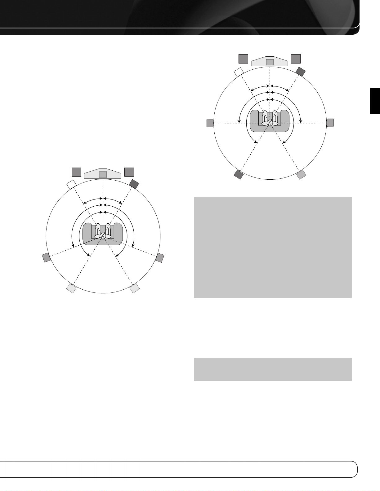
POSITIONNEMENT DES ENCEINTES
C
90°
150°
90°
150°
30° 30°
SBRSBL
FR
FL
SL
SR
Vert
Violet Violet
Rouge
Gris
Brun clair
Marron
Bleu
Blanc
SUB 1 SUB 2
C
Autre disposition pour
l’enceinte latérale
Surround gauche (Bleu)
Autre disposition
pour l’enceinte latérale
Surround droite (Gris)
110°
150°
110°
150°
30° 30°
SUB 1
FR
FL
SL
SR
Vert
Violet
SUB 2
Violet (facultatif)
Rouge
Gris
Bleu
Blanc
Il convient de placer les enceintes sur un cercle dont le centre est la position
d’écoute. Il convient d’orienter les enceintes directement vers la position d’écoute.
Disposition des enceintes frontales
L’enceinte centrale peut être placée au-dessus ou en-dessous de l’écran vidéo, ou
alors accrochée au mur au-dessus ou en-dessous de l’écran.
Les enceintes frontales gauche et droite sont placées sur le cercle, à 30 degrés
environ de l’enceinte centrale et orientées vers l’auditeur.
Placez les enceintes frontales gauche, centrale et droite à la même hauteur, de
préférence à la hauteur des oreilles de l’auditeur. Il convient de ne pas situer l’enceinte centrale à plus de 60 cm au-dessus ou en-dessous des enceintes gauche
et droite. Si vous n’utilisez que deux enceintes avec l’AVR 2600, placez-les dans
les positions frontales gauche et droite.
La disposition des enceintes Surround dépend du nombre d’enceintes de votre
système.
FRANÇAIS
Figure 15 – Disposition des enceintes (système à 7.1 canaux)
Figure 14 – Disposition des enceintes (système à 5.1 canaux)
Disposition des enceintes Surround dans
un système à 5.1 canaux
Il convient de placer les enceintes latérales Surround à 110 degrés par rapport à
l’enceinte centrale, légèrement en arrière et orientées vers l’auditeur. Elles peuvent
également être placées derrière l’auditeur, chaque enceinte Surround orientée vers
l’enceinte frontale du côté opposé (voir la Figure 14). Les enceintes Surround peuvent être placées légèrement plus haut que les oreilles de l’auditeur.
Disposition des enceintes Surround dans
un système à 7.1 canaux
Dans un système à 7.1 canaux les enceintes Surround latérales sont placées à 90
degrés par rapport à l’enceinte centrale, directement de chaque côté de la position
d’écoute. Les enceintes Surround arrière gauche et droite sont placées à 150
degrés par rapport à l’enceinte centrale ou directement en face de l’enceinte frontale du côté opposé (voir la Figure 15).
REMARQUE : Certains fabricants d’enceintes proposent des systèmes à
6.1 canaux, pour les formats Surround à 6.1 canaux, tels que Dolby Digital
EX, DTS-ES (Discrete et Matrix) et DTS Neo:6. Il n’est pas recommandé d’utiliser l’AVR 2600 dans une configuration à 6.1 canaux. L’écoute des formats à
6.1 canaux donne de meilleurs résultats dans un système à 7.1 canaux. Les
deux enceintes Surround arrière restituent les informations du canal Surround
arrière, mais avec le double de puissance et de clarté.
Pour utiliser l’AVR 2600 avec un système d’enceintes à 6.1 canaux, placez
directement l’enceinte Surround arrière unique derrière l’auditeur, mais ne la
connectez pas tant que vous n’ayez pas exécuté la procédure EzSet/EQ pour
un système à 5.1 canaux. Après l’exécution de la procédure EzSet/EQ,
connectez l’enceinte Surround arrière à la sortie enceinte Surround arrière
gauche. Puis suivez les instructions de la section Fonctions évoluées pour
configurer manuellement l’enceinte Surround arrière.
Disposition des subwoofers
La disposition des subwoofers est moins critique car les sons basse fréquence
sont omnidirectionnels. Si vous placez chaque subwoofer près d’un mur ou dans
un coin de la salle, les basse fréquences sont renforcées et peuvent créer un son
« caverneux ». Placez temporairement l’un des subwoofers à l’endroit où l’auditeur
est normalement assis, puis déplacez-vous dans la pièce jusqu’à ce que le rendu
des basses fréquences s’améliore. Placez le subwoofer à cet endroit.
REMARQUE : Votre récepteur donne de meilleurs résultats si des
enceintes du même modèle ou de la même marque sont utilisées dans toutes
les positions.
19
Page 82

MISE EN ROUTE
L’installation de l’AVR 2600 et sa connexion à d’autres composants du système
peuvent être complexes. Pour simplifier l’installation, nous vous suggérons de dessiner votre système avant de commencer à connecter conducteurs et câbles.
Bien que les prises du panneau arrière permettent un vaste éventail de connexions
audio et vidéo aux autres composants, le logiciel de l’AVR distribue les connexions
en 10 sources conventionnelles : Câble/SAT, DVD, TV, Jeu, Passerelle multimédia,
AUX, A, B, C et D. Les sources internes (le syntoniseur, la station d’accueil The
Bridge III pour l’iPod, le port USB, la webradio et le réseau) sont traitées plus loin.
Le Tableau A1 de l’annexe indique les types de périphériques par défaut pour
chaque source ainsi que les sélections de connexions audio/vidéo par défaut. Si
les valeurs par défaut conviennent à votre système, raccordez vos périphériques
aux entrées audio/vidéo indiquées. Dans le cas contraire, dessinez votre système
comme expliqué ci-après.
1. Meilleur type de connexion vidéo pour votre système : Examinez
les entrées vidéo de votre téléviseur ou écran vidéo.
Consigner le meilleur type de connexion vidéo disponible ici :_______________.
Les possibilités sont par ordre de préférence : HDMI, DVI (il doit être compatible
HDCP), vidéo en composantes, S-vidéo ou vidéo composite. C’est la meilleure
connexion vidéo pour votre système.
2. Déterminez la source qui sera utilisée pour chaque périphé-
Faites correspondre jusqu’à 10 périphériques avec les 10 sources
rique :
conventionnelles énumérées dans le Tableau 2 ci-dessous. Utilisez la source AUX
pour l’un de ces type de périphérique : lecteur CD, récepteur HDTV, enregistreur
vidéo personnel, boîtier TiVo ou magnétoscope.
REMARQUE : Vous pouvez faire correspondre n’importe quel type de péri-
phérique avec n’importe quelle source. Le type de périphérique est uniquement important pour la programmation de codes de commandes dans la télécommande et, comme expliqué en page 24, vous pouvez réaffecter n’importe
quel type de périphérique à une touche de sélection de source. N’importe
quelle source audio ou vidéo peut être connectée à n’importe quelle prise
correspondante de l’AVR, quel que soit le type du périphérique.
3. Meilleure connexion vidéo pour chaque source : Examinez chaque
périphérique source et consignez le meilleur type de connexion vidéo disponible,
mais pas meilleur que la meilleure connexion du système. Laissez les sources
audio seulement en blanc, comme un lecteur CD.
4. Meilleure connexion audio pour chaque source : Pour chaque péri-
phérique source, consignez le meilleur type de connexion audio disponible.
Consultez la remarque ci-dessous et si la connexion HDMI peut être utilisée pour
l’audio, c’est le meilleur choix. Les autres possibilités sont par ordre de préférence :
audio numérique optique, audio numérique coaxial, audio analogique à 2 canaux.
REMARQUES :
• Pour les lecteurs de disque multicanaux, si le périphérique et le téléviseur
utilisent des connexions HDMI pour la vidéo, vérifiez dans le manuel d’utilisation du périphérique si celui-ci transmet de l’audio multicanaux sur sa sortie
HDMI. Si c’est le cas, une connexion audio non séparée est nécessaire. Dans
le cas contraire, consignez la connexion audio analogique multicanaux en
plus de tout autre type d’audio. Voir page 27 pour plus d’informations.
• Si le périphérique utilise une sortie DVI compatible HDCP pour la vidéo, raccordez-la à l’une des entrées HDMI de l’AVR au moyen d’un adaptateur
HDMI/DVI, mais une connexion audio séparée est toujours nécessaire.
5. Déterminez les sources à connecter à chaque entrée vidéo :
Affectez uniquement une seule entrée vidéo à chaque source, sauf si vous pouvez
ajouter une connexion vidéo composite pour rendre le signal vidéo de la source
disponible pour le système multizone. Utilisez le meilleur type de connexion vidéo
disponible pour chaque source.
• Si la meilleure connexion vidéo de votre système est « HDMI », sélectionnez jusqu’à quatre périphériques sources HDMI et affectez-les à l’une des quatre entrée
HDMI numérotées.
• Si la meilleure connexion vidéo de votre système est « vidéo en composantes »
ou si vous avez des périphériques sources dotés de sorties vidéo en composantes n’ayant pas été affectées à l’une des entrées HDMI, affectez jusqu’à
deux périphériques à l’une des deux entrées vidéo en composantes numérotées.
• Si la meilleure connexion vidéo de votre système est « vidéo composite » ou si
vous avez des périphériques sources dotés de sorties vidéo composite n’ayant
été affectées à aucune autre entrée vidéo, affectez jusqu’à trois périphériques à
l’une des trois entrées vidéo composite numérotées.
REMARQUE : Si le périphérique source est un enregistreur vidéo qui doit
enregistrer à partir d’autres périphériques connectés à l’AVR, affectez l’enregistreur à l’entrée vidéo 2 ou vidéo composite, qui est dotée d’une sortie
d’enregistrement. N’importe quelle entrée audio numérique coaxiale ou
optique peut être affectée à l’enregistreur si elle peut réaliser des enregistrements audio numériques. Pour réaliser des enregistrements analogiques,
affectez l’entrée audio analogique 2 ou 4 à l’enregistreur car les deux sont
dotées de sorties d’enregistrement. Il n’est pas nécessaire de raccorder le
boîtier TiVo ou l’enregistreur numérique personnel car ils n’enregistreront que
les signaux de télévision câblée ou satellite directement des sorties d’enregistrement de l’AVR.
Tableau 2 – Affectation des sources
Source Type de Meilleure Entrée vidéo Meilleure connexion Entrée audio affectée Entrée audio
Câble/SAT
DVD
TV
Jeu
Passerelle multimédia
AUX
20
périphérique connexion vidéo affectée audio (HDMI, (elle peut être analogique
(HDMI, DVI, vidéo optique, coaxiale, numérique plus pour
en composantes, analogique à une ou plusieurs l’enregistrement
vidéo composite) 2 canaux, analogique analogiques) ou l’utilisation
à 6/8 canaux) multizone
Page 83

6. Déterminez les entrées audio à connecter à chaque source :
Affectez uniquement une entrée audio numérique à chaque source numérique.
Affectez les entrées audio analogiques aux sources analogiques ou en tant que
connexions secondaires pour les sources numériques comme connexion de réserve, pour l’enregistrement ou pour rendre la source disponible au système multizone.
• Toute source utilisant une entrée HDMI ne requiert aucune connexion supplémentaire pour l’audio sauf :
Réalisez une deuxième connexion aux entrées audio analogiques à 6/8 canaux ;
si la source est dotée d’une sortie DVI compatible HDCP pour vidéo uniquement.
Affectez-lui une entrée audio numérique ou analogique.
• À toute source dont la meilleure connexion audio est numérique optique ou
coaxiale, affectez l’une des quatre entrées audio numériques optiques ou l’une
des trois entrées audio numériques coaxiales. Ne raccordez pas deux types
d’audio numérique au même périphérique source.
• Vous pouvez affecter l’une des entrées audio analogiques à 2 canaux à une
source numérique.
• Vous pouvez également affecter les entrées audio analogiques à 6/8 canaux, le
cas échéant, à une source numérique. Voir page 27.
• Affectez l’une des six entrées audio analogiques à 2 canaux à une source analogique.
MISE EN ROUTE
FRANÇAIS
NOTE: Si l’appareil source est un enregistreur audio numérique, il pourra
être utilisé avec n’importe quelle Entrée audio numérique coaxiale ou optique
et avec la Sortie audio numérique coaxiale. Pour réaliser des enregistrements
analogiques, affectez l’entrée audio analogique 2 ou 4 à l’enregistreur car les
deux sont dotées de sorties d’enregistrement.
21
Page 84

INSTALLATION
L’installation de l’AVR est maintenant prête à commencer. Avant de commencer à
connecter les différents composants au récepteur, éteignez tous les périphériques,
y compris l’AVR 2600, puis débranchez leur cordon d’alimentation.
Ne branchez aucun cordon d’alimentation avant d’avoir réalisé toutes les
connexions.
Le récepteur génère de la chaleur. Choisissez un emplacement permettant de laisser un espace de plusieurs centimètres de tous les côtés. Évitez d’enfermer totalement le récepteur dans une armoire non ventilée. Placez les composants sur des
étages différentes plutôt que de les empiler directement sur le récepteur. Ne bouchez jamais les grilles de ventilation des panneaux supérieur et latéraux de l’AVR.
Cela risque de provoquer la surchauffe de l’AVR et d’entraîner des répercussions
potentiellement graves. Certaines étagères ont des finitions délicates.
choisir un emplacement ayant un fini résistant.
Tâchez de
ASTUCE : Pour éviter des erreurs, repérez chaque câble avant de le
brancher. Écrivez une description du câble sur une étiquette adhésive, « DVD
» par exemple, et repliez l’étiquette autour du câble à environ 6" (15 cm) de
l’extrémité à brancher dans l’AVR.
La plupart des étapes suivantes de l’installation sont facultatives et dépendent de
votre système. Sautez toute les étapes qui ne s’appliquent pas à votre système.
ÉTAPE UN – Connectez les périphériques
sources
Sans brancher les cordons d’alimentation secteur, connectez les périphériques
sources à l’AVR dans les entrées audio et vidéo que vous avez affectées dans le
Tableau 2.
2. Tout en tenant le câble avec la partie la plus large du connecteur en bas, pressez délicatement les languettes de chaque côté pour l’insérer dans le connecteur se situant sur la façade arrière. Voir Figure 16.
Figure 16 – Connecteur The Bridge III
3. Placez l’insert noir dans The Bridge III, assurez-vous de bien le pousser jusqu’au
fond. Voir Figure 17.
NOTE: Ne mettez pas un iPod ou un iPhone dans The Bridge III à moins que
l’insert noir et un adaptateur de dock soient tous les deux installés. Sinon,
l’iPod ou l’iPhone ne se connecteront pas correctement et aussi bien cet
appareil que The Bridge III risquent de subir des dommages non couverts par
la garantie.
ÉTAPE DEUX – Connectez le téléviseur
Raccordez la meilleure entrée vidéo du système du téléviseur à la sortie écran
vidéo correspondante de l’AVR.
ÉTAPE TROIS – Connectez les enceintes
Après avoir disposé les enceintes dans la salle comme expliqué en page 21,
connectez chaque enceinte à ses bornes de l’AVR en respectant le code de couleurs. Respectez la polarité en raccordant la borne négative de l’enceinte (généralement noire) à la borne négative de l’AVR (également noire), la borne positive de
l’enceinte (habituellement rouge) à la borne positive de l’AVR (la couleur varie en
fonction du canal, voir le Tableau 1 en page 16).
Si vous avez un subwoofer, raccordez son entrée à niveau de signal ligne ou LFE à
la sortie Subwoofer 1 violette.
REMARQUE : Si le subwoofer n’est pourvu que d’entrées à niveau encein-
te, après avoir configuré l’AVR à l’aide de la technologie EzSet/EQ comme
décrit en page 25, raccordez les bornes d’entrée enceinte gauche et droite du
subwoofer aux sorties enceintes frontales gauche et droite de l’AVR, puis
connectez les enceintes principales frontales gauche et droite aux bornes de
sorties enceintes gauche et droite du subwoofer. Consultez les instructions
d’installation spécifiques au subwoofer dans son manuel d’utilisation.
QUATRIÈME ÉTAPE Connectez le
Dock
Pour bénéficier du contenu stocké sur un iPod ou un iPhone compatible (non compris) :
1. Eteignez l’AVR 2600, en utilisant le bouton Standby/Marche.
Figure 17 – Docker un iPod ou iPhone dans The Bridge III
4. Placez l’adaptateur de dock fourni avec votre iPod ou iPhone, ou sélectionnez
l’un des adaptateurs inclus en vous référant au Tableau 3. Si votre iPod ou
iPhone n’apparaît pas dans le Tableau 3 et ne comprend pas d’adaptateur,
contacter Apple Inc. pour en acheter un. Placer l’adaptateur dans l’insert The
Bridge III, comme indiqué dans la Figure 17.
5. Retirez l’iPod ou l’iPhone de son étui, le cas échéant, et mettez-le dans le dock
The Bridge III, comme indiqué dans la Figure 17.
Tableau 3 – Sélectionner le bon insert
The Bridge III
Insert The Bridge III Modèle d’iPod
NANO iPod nano, 1ère et 2ème générations
5G (VIDEO 60GB) iPod, 5ème génération (60GB,
80GB), et iPod classic (160GB)
5G (VIDEO 30GB) iPod, 5ème génération (30GB), et
iPod classic (80GB)
13 iPod nano, 3ème et 4ème générations
12, 14 iPod touch – installez le gros adaptateur ;
iPhone ou iPhone 3G – installez le petit
adaptateur
22
Page 85

INSTALLATION
ÉTAPE CINQ – Connectez l’antenne FM
Raccordez l’antenne FM fournie à la borne d’antenne FM de 75 ohms.
ÉTAPE SIX – Connectez l’antenne AM
Assemblez l’antenne AM fournie (voir la Figure 18) et raccordez-la aux bornes
d’antenne AM et masse. L’antenne n’est pas polarisée et n’importe lequel de ses
conducteur peut être connecté à chaque borne.
Figure 18 – Assemblage de l’antenne AM
SEPTIÈME ÉTAPE – Connecter le
Syntoniseur SIRIUS
Si vous avez acquis un syntoniseur optionnel conçu pour les appareils SIRIUSReady, branchez-le avec le jack SIRIUS. Souscrivez au service et activez le module, en suivant les instructions indiquées sur www.sirius.com. Placez le module
dans le champ d’une fenêtre faisant face au sud.
ÉTAPE HUIT – Connectez les entrés et
sorties à infrarouge déportées
L’ AV R 2600 est équipé d’une Entrée IR de commande à distance, d’une Entrée
Zone 2, d’une Sortie IR A-BUS et de Sorties IR pour liaison par onde porteuse complète (« full carrier ») ou par onde réduite (« stripped ») de commande à distance
pour faciliter l’utilisation de votre système avec une télécommande dans diverses
situations.
L’ AV R 2600 est équipé d’une entrée IR déportée, une entrée Zone 2 et de deux
sorties IR déportées, l’une à porteuse complète et l’autre démodulée, pour faciliter
l’utilisation de votre système à l’aide de la télécommande dans un vaste éventail
de situations. Si l’AVR 2600 est placé dans une armoire ou orienté dans la direction opposée de l’auditeur, connectez un récepteur à infrarouge externe, tel que
Harman Kardon HE 1000 facultatif, à la prise d’entrée IR déportée. Pour l’utilisation
multizone, connectez un récepteur, une télécommande IR ou un autre dispositif de
commande facultatif à l’entrée IR Zone 2 pour la commande à distance de l’AVR
2600 (et de toutes les sources connectées à la sortie IR déportée de l’AVR) depuis
la zone distante. Les signaux transmis par l’entrée IR Zone 2 commandent la
sélection de source ainsi que le volume de la zone principale ou distante, en fonction de la position du commutateur de sélection de zone de la télécommande.
Pour commander plusieurs périphériques sources par la sortie IR déportée,
connectez toutes les sources en « guirlande », en connectant la sortie IR de
chaque périphérique à l’entrée IR du prochain périphérique, en commençant par
l’AVR. Connectez les périphériques qui exigent un signal IR à porteuse complète à
la sortie Porteuse IR déportée et affectez la zone d’émission souhaitée dans le
menu Zone 2. Utilisez la sortie IR déportée pour les périphériques qui exigent un
signal démodulé.
ÉTAPE NEUF – Installation d’un système
multizone
L’ AV R 2600 offre plusieurs méthodes de distribution audio à d’autres zones de
votre domicile.
NOTE IMPORTANTE DE SÉCURITÉ : L’installation d’un système mul-
tizone exige la pose de câbles dans les murs. Respectez toujours les codes
de sécurité appropriés en installant des câbles dissimulés, et en particulier
tous les codes du bâtiment nationaux et locaux applicables ainsi que le Code
national de l'électricité (NEC). Le non respect de ces codes peut entraîner des
risques pour la sécurité. En cas de doute concernant votre capacité à travailler sur des câblage électriques et de télécommunications, chargez un
électricien ou installateur autorisé de l’installation du système multizone.
Si le système est installé à l’aide de la méthode B ou C décrites ci-dessous, l’utilisation en multizone utilise les canaux d’amplification Surround arrière/Zone 2 et
limite le système dans la salle d’écoute principale à 5.1 canaux.
1. Connexion des enceintes de la salle distante
directement aux sorties enceintes Surround
arrière/Zone 2. Réaffectez les canaux amplificateurs Surround arrière
pour alimenter les enceintes (voir page 42).
2. Connexion de dispositifs de commande à infra-
rouge à l’entrée IR Zone 2
Pour les méthodes A, B et C, connectez un dispositif de commande à infrarouge à
l’entrée IR Zone 2 pour la commande du système multizone, de périphériques
sources et du volume dans la zone distante depuis la salle distante. Un système ABUS ne requiert pas de connexion de commande à infrarouge séparée.
REMARQUE : Seules les sources audio analogiques sont disponibles pour
le système multizone. Pour les sources numériques, réalisez une deuxième
connexion audio analogique. Les sources USB, The Bridge III et webradio sont
disponibles pour le système multizone.
ÉTAPE DIX - Branchez les cordons d'alimentation secteur
Avant de brancher l’AVR dans une prise de courant électrique non commandée,
vérifiez si le l’interrupteur d'alimentation principal situé derrière le capot en façade
est coupé pour éviter la possibilité d’endommager l’AVR en cas de surtension transitoire. S’il est enfoncé, l’interrupteur est allumé. Une nouvelle pression déverrouille l’interrupteur qui ressort.
Vous pouvez raccorder un périphérique qui ne consomme pas plus de 50 watts à
la sortie secteur accessoires commandée du panneau arrière. Allumez l’interrupteur d'alimentation principal ou l’interrupteur mécanique du périphérique et ce
dernier s’allume chaque fois que l’AVR 2600 est allumé (certains périphériques
peuvent exiger des étapes supplémentaires pour s’allumer à partir de leur mode
veille). Si le périphérique est équipé d’une horloge ou doit toujours être allumé
(comme un récepteur réseau câblé programmé pour réaliser des enregistrements),
ne le branchez pas dans cette prise.
Raccordez le cordon d’alimentation secteur à une prise de courant murale non
commandée.
Il est recommandé de copier les informations appropriées du Tableau 2 dans le
Tableau A5 de l’annexe afin de pouvoir les consulter ultérieurement, au cas où des
modifications sont apportées aux composants du système.
ÉTAPE ONZE – Introduisez les piles dans
la télécommande
La télécommande de l’AVR 2600 utilise quatre piles AAA (fournies).
Pour retirer le couvercle des piles au dos de la télécommande, appuyez sur la languette et soulevez le couvercle.
Introduisez les piles comme illustré par la Figure 19 en respectant la polarité.
FRANÇAIS
23
Page 86

INSTALLATION
Figure 19 – Logement des piles de la télécommande
Dirigez la lentille de la télécommande vers la façade de l’AVR 2600. Vérifiez si
aucun objet, tel qu’un meuble, ne gêne la ligne de visée de la télécommande jusqu’au récepteur. Les éclairages puissants, les lampes fluorescentes et les écrans
vidéo à plasma peuvent interférer avec le fonctionnement de la télécommande.
Celle-ci a une portée d’environ 6 mètres suivant les conditions d’éclairage. Elle
peut fonctionner avec un angle allant jusqu’à 30 degrés de chaque côté de l’AVR.
Laissez le commutateur de sélection de zone vers le bas en position Zone 1 pour
une utilisation normale.
S’il semble que la télécommande fonctionne de façon discontinue ou si une pression sur une touche de la télécommande n’éclaire pas la touche Paramètres de
l’AVR ou l’une des touches de sélection de source, vérifiez ou remplacez les piles.
ÉTAPE DOUZE – Programmation des
sources à l’aide de la télécommande
La télécommande de l’AVR 2600 peut être programmée pour commander de nombreux modèles et marques de lecteurs DVD, de récepteurs réseau câblé, de récepteurs satellite, le centre multimédia numérique Harman Kardon DMC 1000 ainsi
que des téléviseurs. Elle est également préprogrammée pour commander votre
iPod lorsqu’il est inséré dans la station d’accueil The Bridge III.
Pour avoir accès aux fonctions d’un appareil spécifique, passez la télécommande
en mode appareil. Appuyez sur le bouton d’installation pour accéder aux codes qui
contrôle le récepteur, ou les touches des Sélecteurs de Sources pour accéder aux
codes des appareils programmés dans la télécommande.
Alors que le Sélecteur de Source DVD peut être utilisé pour faire fonctionner soit
un lecteur de disques Blu-ray Harman Kardon soit un lecteur de DVD Harman
Kardon, le mode par défaut est de commander un lecteur de disques Blu-ray
Harman Kardon. Pour basculer du mode lecteur de disques Blu-ray Harman Kardon
au mode lecteur de DVD, appuyez et maintenez enfoncé le Sélecteur de Source
DVD pendant 2 secondes. Le sélecteur de source flashera deux fois pour confirmer
que le mode de la télécommande a été modifié pour faire fonctionner l’autre type
de lecteur de disques.
Suivez ces étapes pour programmer les bons codes pour chaque appareil source
dans la télécommande :
1. Chercher les codes correspondant au type de produit (ex : DVD, décodeur câble)
et à la marque de votre source dans les Tableaux A14– A24 de l’Annexe.
NOTE: Le Sélecteur de Source AUX est utilisé pour les enregistreurs CD,
HDTV, PVD, ainsi que les appareils de type TiVo et magnétoscope. De la
même manière, le Sélecteur de Source Câble/SAT est utilisé soit pour un
décodeur câble soit pour un décodeur satellite. Le premier chiffre du code
produit indique le type d’appareil.
2. Allumez votre appareil source.
3. Mettez la télécommande en mode programme : appuyez et maintenez enfoncé
le Sélecteur de Source jusqu’à ce qu’il devienne rouge, puis s’éteigne et redevienne rouge. Vous pouvez alors relâcher le bouton.
Optionnel : Pour réassigner un type d’appareil au Sélecteur de Sources (par
exemple, s’il y a deux lecteurs DVD dans le système), appuyez sur le Sélecteur de
Source du nouveau type d’appareil. Par exemple, pour réassigner le Sélecteur de
Source Câble/SAT pour faire fonctionner un lecteur DVD, appuyez d’abord sur et
maintenez enfoncée la Touche Câble/SAT, puis appuyez sur la Touche DVD.
La télécommande est préprogrammée en usine pour faire fonctionner un lecteur de
disques Blu-Ray Harman Kardon lorsqu’en mode appareil DVD. Il n’est pas nécessaire de modifier le type d’appareil pour programmer les codes d’un lecteur DVD.
4. Entrez un code comme indiqué à la Première Étape ci-dessus.
a) Si l’appareil s’éteint, appuyez une nouvelle fois sur le Sélecteur de Source
pour sauvegarder le code. Un flash apparaîtra et la télécommande quittera le
mode Programme.
b) Si l’appareil ne s’éteint pas, entrez un autre code. Si vous vous trouvez à
court de codes, cherchez dans la liste de codes de la bibliothèque de la télécommande pour ce type de produit en appuyant sur les Touches
manière répétée jusqu’à ce que l’appareil s’éteigne. Quand l’appareil s’éteint,
sauvegardez le code en appuyant sur le Sélecteur de Source. Il clignotera et
la télécommande quittera le mode Programme.
5. Vérifiez que les autres fonctions commandent l’appareil correctement. Parfois,
les fabricants utilisent le même code d’Alimentation pour plusieurs modèles,
tandis que d’autres codes varient. Répétez cette procédure jusqu’à ce que vous
ayez programmé un ensemble de codes satisfaisant qui permette de faire fonctionner la plupart des fonctions.
6. Trouvez le numéro de code que vous avez programmé en appuyant sur et en
maintenant enfoncé le Sélecteur de Source pour entrer dans le mode
Programme.
Appuyez sur la Touche OK, et le Sélecteur de Source flashera la séquence de
code. Un flash veut dire « 1 », deux flashs veulent dire « 2 », etc. Une série de
plusieurs flashs rapides veut dire « 0 ». Enregistrez les codes programmés pour
chaque appareil dans le Tableau A9 de l’annexe.
La plupart des étiquettes des touches de la télécommande décrit la fonction de la
touche lorsqu’elle est utilisée pour contrôler l’AVR 2600. Toutefois, la touche peut
effectuer une fonction différente lorsqu’elle est utilisée pour commander un autre
appareil. Se référer à la Liste des fonctions de la télécommande, Tableau A13 de
l’Annexe.
Les activités sont des séquences de codes préprogrammées qui exécutent de
nombreuses commandes de codes par une simple pression de la touche. La programmation par touches permet à la télécommande de diriger une chaîne d’un
appareil ou les commandes de transport tout en étant réglée sur le mode d’un
autre appareil. Voir page 43 pour obtenir des instructions sur ces fonctions de programmation avancées.
1
ou 5de
ÉTAPE TREIZE – Allumez l’AVR 2600
Deux étapes sont nécessaires la première fois que vous allumez l’AVR 2600.
1. Placez l’interrupteur principal de la façade arrière en position « Marche ». Le
voyant d'alimentation en façade devient orange pour indiquer que l’AVR est en
mode veille et qu’il est prêt à être allumé. Normalement, vous pouvez laisser
allumé l’interrupteur d'alimentation principal, même si le récepteur n’est pas en
cours d’utilisation.
2. Il y a plusieurs façons d’allumer l’AVR à partir du mode veille :
a) appuyez sur l’interrupteur Veille/Allumé en façade ;
b) à l’aide de la télécommande, appuyez sur la touche Marche AVR ou l’une des
touches de sélection de source.
REMARQUES :
• Chaque fois que vous appuyez sur une touche de sélection de source de la
télécommande, cette dernière passe à un autre mode périphérique. Pour
commander le récepteur, appuyez sur la touche Paramètres de l’AVR.
Certaines fonctions de l’AVR sont disponibles dans tous les modes périphériques : Commandes de volume (y compris Sourdine), Effets audio, Modes
vidéo, Modes Surround, Paramètres de l’AVR, Paramètres d’informations,
Paramètres de mise en veille et Marche/Arrêt de l’AVR.
• Si vous ne voyez aucune image au bout d’une 1 minute environ, consultez
les Astuces de dépannage vidéo en page 30.
24
Page 87

CONFIGURATION INITIALE
Cette section vous guide pour la configuration de l’AVR 2600 afin de concorder
avec votre système actuel. Un écran vidéo doit être raccordé à l’une des sorties
écran vidéo du récepteur.
UTILISATION DU SYSTÈME DE MENUS
D’ÉCRAN
Bien qu’il soit possible de configurer l’AVR uniquement à l’aide de la télécommande et des messages affichés en façade, il est plus facile d’utiliser le système de
menus plein écran.
On peut accéder au système de menu en appuyant sur le bouton d’installation de
la télécommande ou de la façade avant.
Le menu principal s’affiche (voir la Figure 20), et si une source vidéo est en cours
de reproduction, elle est visible derrière le menu transparent.
Figure 20 – Menu principal
REMARQUE : Si vous utilisez le système de menus d’écran de l’AVR, une
résolution de la sortie vidéo de 720p ou supérieure est recommandée pour
une meilleure lisibilité et pour afficher des graphiques qui simplifient certaines options de configuration. En fonction de la résolution choisie, l’aspect
des menus affichés par votre système peut varier.
Jusqu’à une date récente, la plupart des récepteurs devaient être réglés et configurés manuellement, un processus fastidieux exigeant une bonne oreille ou l’acquisition d’un calibreur de niveau de pression acoustique. Bien que vous puissiez
configurer l’AVR 2600 manuellement, comme décrit dans la section Fonctions évoluées, il est recommandé de tirer parti du système EzSet/EQ de Harman Kardon
signature.
Supprimez tous les bruits de fond extérieurs, comme un climatiseur bruyant. Évitez
de faire du bruit pendant l’exécution du paramétrage EzSet/EQ.
NOTE IMPORTANTE DE SÉCURITÉ : Pendant la procédure EzSet/EQ,
toutes les enceintes sont soumises à une série de balayages d’essai très
bruyants. Évitez de vous asseoir ou de vous tenir trop près d’une des
enceintes pendant la procédure. Si vous êtes particulièrement sensible aux
bruits intenses, il est préférable que vous quittiez la salle et confiez l’exécution du processus EzSet/EQ à une autre personne.
ÉTAPE UN – Placez le microphone EzSet/EQ fourni dans la position
d’écoute ou au centre de la salle, à peu près à la même hauteur que les oreilles
des auditeurs. Le microphone est pourvu d’une douille filetée à sa base pour pouvoir le monter sur la perche rallonge fournie ou un trépied d’appareil photo.
ÉTAPE DEUX – Branchez le microphone EzSet/EQ dans la prise d’entrée
de microphone EzSet/EQ en façade du récepteur et réglez la commande du niveau
sur le subwoofer à mi-volume.
ÉTAPE TROIS – Allumez l’AVR 2600 et l’écran vidéo. Appuyez sur la
touche Paramètres de l’AVR pour afficher le menu principal. À l’aide de la touche
5, mettez en évidence la ligne Configuration des enceintes, puis appuyez sur la
touche OK (voir la Figure 21).
FRANÇAIS
Le système du menu principal comprend cinq sous-menus : Sélection de la source, Configuration de la source, Configuration des enceintes, Zone 2 et Système.
À l’aide des touches
le système de menus puis appuyez sur la touche OK pour sélectionner un menu ou
une ligne de paramètre, ou encore pour saisir un nouveau paramètre.
Le menu, ligne de paramètre ou paramètre actuel s’affiche sur l’Afficheur de messages ainsi que sur l’écran.
Pour revenir au menu précédent ou quitter le système de menus, appuyez sur la
touche Précédent/Quitter. Vérifiez que tous les paramètres soient corrects car tous
les changements que vous introduisez sont enregistrés.
Il convient que la plupart des utilisateurs suivent les instructions de cette section
Configuration initiale pour configurer un système de cinéma à domicile de base.
Vous pouvez accéder à nouveau à ces menus à tout moment pour effectuer des
réglages supplémentaires, comme ceux décrits dans la section Fonctions évoluées.
Avant de commencer Configuration initiale, il convient de connecter toutes les
enceintes, un écran vidéo et tous les périphériques sources. On doit pouvoir allumer le récepteur et visualiser le menu principal en appuyant sur le Bouton d’installation. Si nécessaire, relisez la section Installation et le début de la présente section avant de poursuivre.
1/57/3 de la télécommande ou en façade, naviguez dans
Configuration de l’AVR 2600,
utilisation de la technologie EzSet/EQ
Une des étapes les plus importantes de la configuration d’un système de cinéma à
domicile est le réglage du récepteur de manière à concorder avec les enceintes,
pour optimiser la reproduction sonore.
Figure 21 – Écran du menu Configuration des enceintes
Sélectionnez “Installation automatique-EzSet/EQ”, et l’écran montré à la Figure 22
apparaîtra.
Figure 22 – Ecran EzSet/EQ
Pour revenir au menu Configuration des enceintes sans lancer le processus
EzSet/EQ, sélectionnez Précédent. Quand vous êtes prêts à commencer, sélectionnez Continuer.
25
Page 88

CONFIGURATION INITIALE
REMARQUE : L’ AV R 2600 règle automatiquement son volume principal à
–25 dB.
QUATRIÈME ÉTAPE – Après avoir sélectionné “Suite”, l’écran mon-
tré à la Figure 23 apparaîtra. Sélectionnez le nombre de haut-parleurs dans votre
système. Sélectionnez 5.1 s’il n’y a pas d’enceinte surround arrière ou si les
canaux surround arrière sont utilisés pour un fonctionnement multizone.
Figure 23 – EzSet/EQ: Nombre de Haut-Parleurs
NOTE:
Si votre système est composé de moins de cinq haut-parleurs, n’utilisez pas le procédé EzSet/EQ. Procédez plutôt de la façon décrite à la section
Fonctions avancées. Si vous avez sélectionné une configuration 6.1-canaux
avec une seule enceinte surround arrière, utilisez la configuration automatique EzSet/EQ pour les haut-parleurs 5.1, connectez l’unique enceinte surround arrière à la Sortie Enceinte Surround Arrière gauche, puis configurez
l’enceinte surround arrière manuellement, tel que décrit à la section
Fonctions avancées. La configuration 6.1-canaux n’est pas recommandée. Si
le subwoofer doit être connecté aux Sorties Enceintes Avant, ne connectez
pas le caisson de graves (subwoofer) avant d’avoir lancé le procédé
EzSet/EQ.
Le test commencera et l’écran montré à la Figure 24 apparaîtra. Gardez le silence
pendant la configuration EzSet/EQ.
Figure 24 – EzSet/EQ en cours
Quand le système EzSet/EQ réalise l’essai de chaque enceinte, sa position s’affiche à l’écran. Si le balayage de l’essai s’entend dans une enceinte différente de
celle qui indiquée à l’écran, éteignez l’AVR et vérifiez les connexions des câbles
d’enceintes, puis recommencer l’essai. Quand l’essai de détection d’enceintes est
terminé, sélectionnez l’option Continuer.
•
Réglages de visualisation : Sélectionnez cette fonction pour
visualiser les résultats de la procédure EzSet/EQ.
Effectué: Sélectionnez cette fonction pour retourner au menu
•
d’Installation des Haut-Parleurs.
Voir la section Fonctions avancées pour obtenir des instructions sur la configuration manuelle des haut-parleurs ou l’ajustement manuel des réglages établis par la
procédure EzSet/EQ
Configuration des sources
Le menu Paramètres d’informations permet d’affecter les connexions matérielles
audio et vidéo correctes à chaque source.
Les paramètres suivants ne sont pas facultatifs et doivent être réglés à ce moment
pour permettre la reproduction de chaque source : Entrée vidéo à partir de la source, Entrée audio à partir de la source et Résolution d’affichage. Les autres paramètres peuvent être réglés ultérieurement.
Pour afficher le menu Paramètres d’informations, appuyez sur la touche
Paramètres d’informations (en façade ou sur la télécommande), ou alors, dans le
menu principal, sélectionnez la ligne Configuration de la source et sélectionnez
une source dans le menu escamotable. Un écran similaire à celui illustré par la
Figure 25 s’affiche.
Figure 25 – Menu Configuration des sources
Effets Audio : Affiche le sous-menu Effets Audio, qui permet d’ajuster le
réglage du Volume Dolby, les commandes de tonalités graves et aigües, l’état LFE,
le réglage marche/arrêt de la Balance et l’amélioration MP3 indépendamment pour
chaque source. Laisser les réglages par défaut de ce sous-menu, et retournez-y
plus tard si votre système requiert un réglage plus fin. Voir la section Fonctions
avancées pour plus d’informations.
Modes vidéo : Il affiche le sous-menu Modes vidéo qui vous permet
d’effectuer des réglages d’image pour chaque source séparément. Conservez les
paramètres d’usine par défaut. Il convient d’effectuer les réglages d’image d’abord
sur votre écran vidéo et utiliser ce menu uniquement pour les réglages fins. Voir la
section Fonctions évoluées pour de plus amples informations.
Modes Surround : Il affiche le sous-menu Modes Surround qui vous
permet de programmer les modes Surround pour les films, la musique et les jeux
analogiques pour chaque source séparément.
Les signaux Surround numériques, tels que Dolby Digital et DTS, sont reproduits
automatiquement dans leurs formats natifs, bien que vous puissiez modifier le
mode Surround. Voir la section Fonctions évoluées pour de plus amples informations.
Format audio à partir de la source : Cette ligne n’est
qu’à titre indicatif. Si un programme numérique est reproduit, son format est identifié sur cette ligne. Lorsque des programmes audio analogiques sont reproduits,
cette ligne affiche ANALOG.
Sélection d’entrée audio et vidéo
Le Tableau A2 de l’annexe énumère les affectations des entrées configurées en
usine pour chaque source. Vous pouvez affecter toute entrée disponible à n’importe quelle source à l’aide du menu Paramètres d’informations.
Quand une source est sélectionnée, l’AVR vérifie si l’entrée audio numérique affectée présente un signal. Si c’est le cas, l’entrée numérique est sélectionnée. Dans le
cas contraire, l’AVR sélectionne l’entrée audio analogique spécifiée dans la ligne
Scrutation automatique audio du menu Paramètres d’informations. Si vous ne souhaitez pas que l’AVR sélectionne une entrée audio analogique pour la source,
conservez le paramètre par défaut : Désactivé.
26
Page 89

CONFIGURATION INITIALE
L’AVR détecte également la source vidéo affectée. Les sources « audio seulement »
de l’AVR 2600 sont la radio, The Bridge III (les vidéos peuvent être disponibles, voir
page 32), qui utilisent des menus spéciaux à l’écran. Pour les sources externes,
s’il n’y a pas de signal vidéo, l’affichage restera noir. Vous pouvez apparier un périphérique audio avec le signal vidéo d’un périphérique audiovisuel à l’aide du menu
Paramètres d’informations. Les sources peuvent partager des entrées audio ou
vidéo.
REMARQUE : The Bridge II obtient ses signaux audio et vidéo (le cas
échéant) de l’iPod ou iPhone qui y est inséré et il ne devrait pas être utilisé
avec d’autres sources audio ou vidéo.
Entrée vidéo à partir de la source : Affectez l’entrée vidéo
appropriée. Consultez le Tableau 2 dans lequel vous avez consigné l’entrée vidéo
matérielle à laquelle la source est connectée et sélectionnez cette entrée pour ce
paramètre.
Entrée audio à partir de la source : Affectez la bonne
entrée audio analogique ou numérique. Consultez le Tableau 2 dans lequel vous
avez consigné l’entrée audio matérielle à laquelle la source est connectée et
sélectionnez cette entrée pour ce paramètre. Si les deux connexions audio analogique et numérique sont réalisées, sélectionnez l’entrée numérique pour ce paramètre et sélectionnez l’entrée analogique aux lignes Scrutation automatique audio
et Audio Zone 2 ci-dessous.
Entrées à 6/8 canaux
Les entrées audio analogiques à 6/8 canaux sont utilisées pour la reproduction de
certains disques multicanaux (DVD-Audio, Blu-ray Disc, SACD et HD-DVD) sur un
lecteur qui décode le signal audio et le délivre sur ses sorties audio analogiques
multicanaux mais pas sur sa sortie HDMI.
Lecteur de disque multicanaux HDMI :
• Connectez la sortie HDMI du lecteur à des entrées HDMI de l’AVR. Aucune autre
connexion n’est nécessaire.
• Affectez l’entrée HDMI aux entrées audio et vidéo dans les paramètres source.
Lecteur de disque multicanaux HDMI ne délivrant
pas de signal audio multicanaux par une
connexion HDMI :
• Connectez la sortie HDMI et les sorties audio analogiques multicanaux du lecteur
à l’une des entrées HDMI de l’AVR ainsi qu’aux entrées audio analogiques à 6/8
canaux de l’AVR.
• Affectez l’entrée HDMI aux entrées audio et vidéo dans les paramètres source.
• Lorsque vous écoutez des disques DVD vidéo, de CD ou d’autres contenus délivrant un signal audio numérique à définition standard, n’effectuez aucun changement si l’entrée HDMI est affectée au paramètre Entrée audio à partir de la
source.
• Pour écouter des disques multicanaux à haute résolution, changez le paramètre
Entrée audio à partir de la source à « 6/8 canaux ».
Remettez ce paramètre sur Entrée HDMI pour
écouter des contenus numériques à définition
standard.
Lecteur de disque multicanaux dépourvu de sortie HDMI ou écran vidéo dépourvu
d’entrée HDMI :
• Connectez les sorties vidéo en composantes du lecteur à un groupe d’entrée
vidéo en composantes de l’AVR. Suivant les possibilités du lecteur et de votre
écran vidéo, il vous faut plutôt utiliser une connexion vidéo composite.
• Connectez la sortie audio numérique du lecteur à une entrée audio numérique
de l’AVR.
• Connectez les sorties audio multicanaux du lecteur aux entrées audio analogiques à 6/8 canaux de l’AVR.
• Affectez les entrées audio numérique et vidéo analogique correctes aux paramètres Entrée audio à partir de la source et Entrée vidéo à partir de la source.
• Lorsque vous écoutez des disques DVD vidéo, de CD ou d’autres contenus délivrant un signal audio numérique à définition standard, n’effectuez aucun changement si l’entrée HDMI est affectée au paramètre Entrée audio à partir de la
source.
• Pour écouter des disques multicanaux à haute résolution, changez le paramètre
Entrée audio à partir de la source à « 6/8 canaux ». Remettez ce paramètre sur
Entrée HDMI pour écouter des contenus numériques à définition standard.
NOTE: Les Entrées des Canaux 6/8 transmettent les signaux entrants direc-
tement aux commandes de volume, sans les numériser ou les traiter. Il n’est
pas possible de changer le mode surround ou d’ajuster l’une des commandes
audio du menu Effets Audio lorsque l’on utilise les Entrées des Canaux 6/8.
Configurez les réglages de gestion des basses (taille des haut-parleurs, retard
et niveau de sortie) sur votre appareil source pour qu’ils correspondent aux
réglages programmés suivant la procédure EzSet/EQ, qui peuvent être visualisés en utilisant le menu d’Installation des haut-parleurs (voir section
Fonctions avancées). Consultez le guide d’installation de votre lecteur multicanaux pour plus d’informations.
Résolution vers l’écran :
Ce paramètre indique la résolution de la sortie vidéo en fonction des possibilités de
l’écran vidéo.
• If the display is connected to the AVR’s HDMI Output, the two devices will communicate with each other, and the AVR will automatically select the best available video output resolution.
• If the display is connected to the AVR’s Component Video Outputs, there is no
automatic detection of the display’s capabilities, and the video output resolution
must be manually adjusted to match the display’s capabilities (which may be
obtained from the display’s manual or its manufacturer’s Web site).
• If the display is connected to the AVR’s Composite Video Monitor Output, the
video output resolution must be set to 480i (the factory default) to view any
content, including the AVR’s own menus.
Ajuster la résolution en appuyant sur la touche Résolution de la façade avant et en
utilisant les touches
de Messages de la façade avant. Pour le vidéo composite, le bon réglage est 480i.
Pour le composant vidéo, il s’agit de la résolution la plus élevée lorsqu’une image
est visible. On vous demandera d’accepter ou d’annuler le changement de résolution, le message ANNULER apparaîtra sur la façade avant. Appuyez sur la touche
1/5 jusqu’à ce que le bon réglage apparaisse sur l’Affichage
5 pour voir l’option ACCEPTER, puis appuyer sur la touche OK.
REMARQUE : Si l’écran est pourvu d’une entrée DVI connectée à l’AVR
par l’intermédiaire d’un adaptateur HDMI/DVI, l’image est déformée ou muette si l’écran n’est pas compatible HDCP. Dans ce cas, une autre connexion
vidéo doit être utilisée (vidéo en composantes ou vidéo composite).
FRANÇAIS
27
Page 90

CONFIGURATION INITIALE
Résolution à partir de la source : Uniquement à titre indica-
tif. Il indique la résolution de la sortie vidéo par le périphérique source.
Bypass HDMI : Si le signal d’une source HDMI est en cours d’utilisation
et si le système comprend un écran équipé HDMI, le mode Bypass HDMI véhicule
le signal source directement à la sortie HDMI en court-circuitant tous les traitements vidéo de l’AVR, y compris l’ajustement de résolution de sortie vidéo. Pour
permettre à l’AVR le traitement de tous les signaux vidéo, y compris le « mélange »
des signaux vidéo source avec ses messages et menus affichés à l’écran de telle
sorte que vous puissiez ajuster l’AVR sans perdre aucune partie du programme,
désactivez ce paramètre. Quand le mode Bypass HDMI est activé, il est impossible
de « mélanger » le signal source vidéo avec les menus affichés à l’écran de l’AVR.
Si une touche quelconque de la télécommande ou de la façade est enfoncée, l’AVR
sort momentanément du mode Bypass HDMI et affiche le menu sur un fond noir à
l’écran. Après l’effacement du menu de l’écran, soit par écoulement de la temporisation soit après une pression sur la touche Précédent/Quitter, l’AVR revient au
mode Bypass HDMI.
Modification du nom : Il permet de modifier le nom affiché de
votre source ; c’est utile si le type de périphérique source est différent des noms
de sources disponibles. Sélectionnez cette ligne et utilisez les touches 1/5 pour
faire défiler vers l’avant ou vers l’arrière les caractères alphanumériques.
Quand le caractère souhaité apparaît, déplacez le curseur à l’aide de la touche 3
jusqu’à la position suivante. Déplacez à nouveau le curseur si vous souhaitez insérer un caractère d’espacement. Lorsque vous avez terminé, appuyez sur la touche
OK. Le nom s’affiche en façade et à côté du nom original, par exemple DVD, dans
tout le système de menus d’écran. Pour effacer la saisie sans enregistrer aucune
modification, faites défiler les caractères jusqu’au caractère d’espacement situé
avant le « A ».
Synchronisation labiale : Il resynchronise les signaux audio et
vidéo à partir d’une source pour éliminer un problème de « synchronisation labiale
». Les problèmes de synchronisation labiale peuvent se produire lorsque la partie
vidéo d’un signal subit un traitement supplémentaire dans la source ou l’écran
vidéo. L’ajustement de synchronisation labiale s’affiche de lui-même et vous permet de visualiser la vidéo tout en écoutant l’audio. À l’aide des touches 7/3, retar-
dez le signal audio jusqu’à 180 ms (voir la Figure 26).
Audio Zone 2 : Il détermine la source audio pour la zone distante du
système multizone. Sélectionnez l’entrée audio analogique à laquelle la source est
connectée. L’audio numérique n’est pas disponible pour le système multizone.
Appuyez sur la touche Précédent/Quitter, puis revenez sur la ligne Configuration de
la source dans le menu principal pour configurer la source suivante. Quand vous
avez terminé, appuyez sur la touche Précédent/Quitter pour faire quitter les
menus.
Vous êtes désormais prêt à commencer à utiliser votre nouveau récepteur !
Figure 26 – Ajustement de la synchronisation labiale
Scrutation automatique audio : Elle est utilisée lorsque les
connexions audio analogique et numérique sont réalisées. En l’absence de signal
numérique, l’AVR commute automatiquement sur l’entrée audio analogique.
Ceci peut être utile pour les anciens systèmes de télévision par câble qui émettent
des chaînes en audio analogique et numérique.
Si une connexion audio analogique est réalisée, sélectionnez-la ici. Dans le cas
contraire, choisissez le paramètre Désactivé et l’AVR utilise toujours la connexion
audio numérique.
28
Page 91
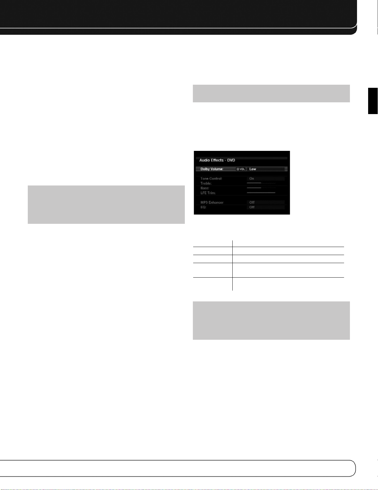
UTILISATION
Après avoir installé vos composants et effectué une configuration de base, vous
pouvez commencer à utiliser votre système de cinéma à domicile.
MISE EN ROUTE DE L’AVR 2600
Placez l’interrupteur principal de la façade arrière en position « Marche ».
L’indicateur d’Alimentation de la façade avant devient jaune, ce qui indique que
l’AVR est en mode Standby et est prêt à être allumé. L’interrupteur d’alimentation
est généralement laissé allumé.
Il y a plusieurs façons d’allumer l’AVR 2600 :
a) appuyez sur l’interrupteur Veille/Allumé en façade ;
b) à l’aide de la télécommande, appuyez sur la touche Marche AVR ou l’une des
touches de sélection de source.
Pour éteindre le récepteur, appuyez sur l’interrupteur Veille/Allumé en façade ou
sur la Touche Arrêt AVR de la télécommande. À moins que vous n’ayez pas l’intention d’utiliser le récepteur pendant une longue période, laissez l’interrupteur d'alimentation principal toujours allumé. Quand l’interrupteur d'alimentation principal
est éteint, tous les paramètres que vous avez programmés sont conservés pendant
quatre semaines.
REMARQUE IMPORTANTE : Si le message « PROTECTION » s’affiche
sur l’afficheur de messages, éteignez l’AVR et débranchez-le. Vérifiez si les
câbles des enceintes ne sont pas en court-circuit. Si ce n’est pas le cas,
apportez l’appareil à un centre de service autorisé Harman Kardon pour son
inspection et réparation avant de l’utiliser à nouveau.
recréer la présentation de référence entendue dans le studio d’enregistrement
sans perdre de portions du programme aux niveaux de volumes généralement plus
bas utilisés à domicile. Lorsque le module de Restitution est actif, on peut noter
des détails de performance qui étaient dissimulés lorsque l’on jouait le programme
sur d’autres appareils.
REMARQUE : Le processeur de Volume Dolby n’est pas utilisé pour niveler
le volume entre différentes sources.
Pour ajuster le paramètre Volume Dolby, appuyez sur la touche Effets audio. Un
écran similaire à celui illustré par la Figure 24 s’affiche. Déplacez le curseur jusqu’à
mettre en évidence le paramètre Volume Dolby ; chaque pression sur la touche OK
commute une des options du Tableau 3 ci-après. Les paramètres ne concernent
pas le volume qui est normalement ajusté à l’aide de la commande de volume,
mais plutôt l’importance du traitement Volume Dolby souhaité (voir la Figure 27).
Figure 28 – Réglage du Volume Dolby
FRANÇAIS
COMMANDES DE VOLUME
Ajustez le volume soit en tournant le bouton en façade (dans le sens horaire pour
augmenter le volume ou dans le sens antihoraire pour diminuer le volume) soit en
appuyant sur la commande de volume de la télécommande. Le volume est affiché
comme une valeur négative de décibels (dB) inférieure à 0 dB qui est le point de
référence.
0 dB est le volume maximal recommandé pour l’AVR 2600. Bien qu’il soit possible
d’augmenter d’avantage le volume, en le faisant vous risquez d’endommager vos
enceintes et d’occasionner des dommages irréversibles à votre système auditif.
Pour certains documents sonores plus dynamiques, même 0 dB peut être une
valeur trop élevée qui peut endommager votre équipement. Soyez prudent quant
au volume.
Pour changer l’affichage du volume de l’échelle par défaut en décibels par une
échelle de 0 à 90, modifiez le paramètre Unités de volume dans le menu
Paramètres du système, comme décrit en page 42.
Volume Dolby
L’ AV R 2600 comprend le traitement de Volume Dolby, qui peut améliorer la performance audio du système en révélant de subtils détails même à des volumes normaux pour une écoute à domicile.
Une des préoccupations des auditeurs de systèmes de cinéma à domicile est que
le volume peut varier considérablement entre différents programmes reproduits
par une source, par exemple le niveau sonore des publicités commerciales de la
télévision est souvent beaucoup plus élevé que celui du programme principal.
Les auditeurs pensent également que les détails perçus en studio d’enregistrement à des volumes de référence habituellement très élevés se perdent aux
volumes plus faibles utilisés par la plupart des auditeurs.
L’ AV R 2600 utilise deux techniques de Volume Dolby pour résoudre ces problèmes.
Le module d’Egalisation maintient un volume d’écoute constant pour une même
source, par exemple lorsque l’on regarde une publicité télévisée ou que l’on écoute différentes pistes d’un CD de données. Le module de Restitution tente de
Tableau 4 – Paramètres de Volume Dolby
Paramètre Effet
Désactivé Pas de traitement du Volume Dolby
Faible Seul le module de modelage du Volume Dolby est activé
Moyen Les deux modules, modelage et nivelage, sont activés ;
le module de nivelage a une valeur de 3
Maxi Les deux modules, modelage et nivelage, sont activés ;
le module de nivelage a une valeur de 9
REMARQUE : Le Volume Dolby est compatible avec les sources enregis-
trées à une fréquence d'échantillonnage de 48 kHz. Les sources à haute
résolution, comme DTS 96/24, sont décodées à 48 kHz. Les programmes DTS
96/24 sont reproduits en mode DTS 5.1. Pour écouter des contenus DTS
96/24 en haute résolution, désactivez le Volume Dolby.
Décalage du réglage Volume Dolby
Le Décalage du réglage est une fonction du Volume Dolby qui permet d’ajuster le
réglage de l’AVR 2600 pour l’adapter de façon optimale avec vos enceintes et
votre environnement d’écoute. L’AVR 2600 est réglé par rapport à la sensibilité
d’enceinte moyenne ; cependant, des enceintes différentes peuvent avoir des sensibilités différentes. Utilisez le décalage du réglage pour ajuster le réglage de l’AVR
2600 en fonction du type de vos enceintes.
La sensibilité moyenne des enceintes audio domestique est de 88 dB SPL (pour 1
watt à 1 mètre sous 8 ohms). Vérifiez la spécification de sensibilité de vos
enceintes dans leur manuel d’utilisation ou sur le site Web du fabricant. Si vos
enceintes ont une sensibilité nominale supérieure à 88 dB SPL, augmentez le
décalage du réglage de la différence entre la sensibilité de vos enceintes et 88 dB.
Si elles ont une sensibilité nominale inférieure à 88 dB SPL, diminuez le décalage
du réglage de la différence entre la sensibilité de vos enceintes et 88 dB.
29
Page 92

UTILISATION
Pour ajuster le décalage du réglage, appuyez sur la touche Paramètres de l’AVR et
faites défiler les menus jusqu’à Configuration du système, puis sélectionnez ce
dernier. Faites défiler les lignes jusqu’à Réglage du Volume Dolby dont la valeur
par défaut est 0 dB. À l’aide des touches 7/3, ajustez le paramètre entre –10 dB
et +10 dB.
FONCTION SOURDINE
Pour mettre temporairement toutes les enceintes ainsi que le casque d’écoute en
sourdine, appuyez sur la touche Sourdine de la télécommande. Elle n’a aucun effet
sur les enregistrements en cours. Le message SOURDINE s’affiche pour vous le
rappeler. Pour restaurer le volume sonore normal, appuyez à nouveau sur la touche
Sourdine ou réglez le volume. L’extinction de l’AVR met également fin à la sourdine.
MINUTEUR DE MISE EN VEILLE
Le minuteur de mise en veille fait fonctionner l’AVR jusqu’à 90 minutes puis il
l’éteint automatiquement.
Appuyez sur la touche Paramètres de mise en veille de la télécommande pour afficher le temps jusqu’à l’extinction. Chaque pression supplémentaire sur la touche
Paramètres de mise en veille diminue le temps d’utilisation de 10 minutes, avec
un maximum de 90 minutes. Le paramètre « Mise en veille désactivée » désactive
le minuteur de mise en veille.
Quand le minuteur de mise en veille est configuré, la luminosité de l’afficheur de
façade baisse automatiquement de moitié et la commande de volume s’éteint.
Si vous appuyez sur la touche Paramètres de mise en veille après que le minuteur
ait été configuré, le temps d’utilisation restant s’affiche. Appuyez à nouveau sur la
touche Paramètres de mise en veille pour modifier le temps d’utilisation.
EFFETS AUDIO
Ajustement du paramètre Volume Dolby, des commandes de tonalité, du niveau du
canal LFE ou des l’égalisation, ou encore sélection d’une configuration d’enceintes
pour en améliorer la performance. Accédez à ces paramètres dans le sous-menu
Effets audio, comme décrits dans la section Fonctions évoluées.
Il est recommandé de conserver les valeurs par défaut des paramètres jusqu’à ce
que vous vous soyez familiarisé avec votre système.
SÉLECTION DE SOURCE
Appuyez sur la touche Liste de Sources de la façade avant. Utilisez les Touches
5/1 pour faire défiler les sources. En utilisant les menus affichés à l’écran,
appuyez sur le Bouton d’installation, sélectionnez « ·Sélecteur de Source » et
appuyez sur la touche OK. Faites défiler le menu jusqu’à la source souhaitée et
appuyez sur la touche OK.
Pour accéder directement à une source, appuyez sur sa touche de sélection de
source de la télécommande.
L’AVR sélectionne les entrées audio et vidéo affectées à la source et tous les
autres paramètres définis au cours de la configuration.
Le nom de la source, les entrées audio et vidéo assignées à cette source, et le
mode surround apparaîtront sur la façade avant. Le nom de la source et le mode
surround apparaîtront également à l’écran.
ASTUCES DE DÉPANNAGE VIDÉO :
S’il n’y a pas d’image :
• vérifiez la source sélectionnée et l’affectation d’entrée vidéo ;
• vérifiez si le câblage ne présente pas de connexion desserrée ou incorrecte ;
• vérifiez l’entrée vidéo sélectionnée sur périphérique d'affichage (téléviseur) ;
• appuyez sur la touche Résolution en façade et sélectionnez la résolution de
sortie vidéo correcte à l’aide des touches 1/5 pour faire apparaître une
image. Le message ANNULER s’affiche. Appuyez sur la touche 5 pour afficher l’option ACCEPTER, puis appuyez sur la touche OK.
Astuces supplémentaires pour les connexions HDMI :
• éteignez tous les périphériques (y compris le téléviseur, l’AVR et tous les
composants sources) ;
• débranchez les câbles HDMI en commençant par le câble reliant le téléviseur et l’AVR puis avec les câbles raccordant l’AVR à chaque périphérique
source ;
• rebranchez soigneusement les câbles entre les périphériques sources et
l’AVR. Connectez le câble entre l’AVR et le téléviseur en dernier ;
• allumez les périphériques dans l’ordre suivant : téléviseur, AVR, périphériques sources.
MODES VIDÉO
Les paramètres du menu Modes vidéo permettent un réglage fin de l’image, si
nécessaire, après avoir effectué tous les réglages de l’écran vidéo. Il est recommandé de conserver leurs valeurs par défaut des paramètres (voir la section
Fonctions évoluées pour de plus amples informations).
CASQUE D’ÉCOUTE
Branchez la prise 1/4-pouce d’un casque d’écoute au jack avant pour écouter de
façon privée. Le mode de dérivation par casque d’écoute par défaut livre un son
conventionnel de deux canaux au casque.
Appuyez sur la touche Modes Surround de la télécommande ou en façade pour
passer au traitement Surround virtuel Dolby Headphone qui émule un système
d’enceintes à 5.1 canaux. Aucun autre mode Surround n’est disponible pour le
casque d’écoute.
30
UTILISATION DU SYNTONISEUR
Pour sélectionner le syntoniseur incorporé de l’AVR 2600 :
1. Appuyez sur la touche Liste de sources en façade. À l’aide des touches 1/5,
sélectionnez la bande de fréquences souhaitée.
2. Appuyez sur la touche de sélection de source Radio de la télécommande.
Appuyez à nouveau sur cette touche pour commuter les bandes de fréquence
(AM, FM ou SIRIUS).
Un écran similaire à celui illustré par la Figure 28 s’affiche. L’utilisation de la
bande SIRIUS affiche un écran différent.
Figure 28 – Radio FM
Page 93

UTILISATION
À l’aide des touches 1/5 ou de la touche Chaîne, syntonisez une station (ou un
canal pour la radio SIRIUS) affichée en façade ou à l’écran.
Par défaut, l’AVR réalise une syntonisation automatique, c’est-à-dire que chaque
pression sur les touches 1/5 lance un balayage sur toutes les fréquences jusqu’à
ce qu’une station délivrant une intensité de signal acceptable soit détectée. Pour
passer en syntonisation manuelle où chaque pression sur les touches 1/5 , fait progresser d’un seul incrément de fréquence (0,1 MHz en FM et 10 kHz en AM),
appuyez sur la touche Menu. La ligne Mode affiche le paramètre actuel. Chaque
pression sur la touche OK commute entre les modes de syntonisation automatique
et manuel.
Lorsqu’une station FM est syntonisée, la commutation entre les modes de syntonisation inclut également la reproduction stéréo et mono, cette dernière améliore la
réception des stations plus faibles.
30 stations (AM et FM comprises) au total peuvent être présélectionnées. Lorsque la
station souhaitée est syntonisée, appuyez sur la touche OK et deux tirets clignotent
sur l’afficheur en façade. À l’aide des touches alphanumériques, saisissez le numéro
de présélection souhaité.
Pour syntoniser une station présélectionnée, appuyez sur les touches 7/3 ou les
touches de commandes de lecture I
pour atteindre la présélection souhaitée, puis appuyez sur la touche OK ; vous pouvez également saisir le numéro présélectionné à l’aide des touches numériques.
Pour les présélections de 10 à 30, saisissez 0 avant le numéro de la présélection.
Par exemple, pour choisir la station 21, saisissez 0-2-1.
‹‹/››
I ou encore appuyez sur la touche Menu
OPERATION RADIO SATELLITE SIRIUS
Pour écouter la Radio Satellite, vous devrez connecter un syntoniseur Radio Satellite
SIRIUS (vendu séparément) à votre récepteur SIRIUS Ready. La Radio Satellite SIRIUS
est disponible pour les personnes résidant aux Etats-Unis (à l’exception de l’Alaska et
de Hawaii) et au Canada.
La Radio Satellite permet d’écouter une grande variété de musique sans publicité
parmi plusieurs catégories, dont Pop, Rock, Country, R&B, Dance, Jazz, Classique et
beaucoup d’autres, en sus de la couverture de tous les principaux sports au niveau
professionnel et universitaire, y compris les matchs minute par minute de ligues et
équipes choisies.
Parmi les autres programmes possibles figurent des discussions entre experts sportifs, du divertissement non censuré, des comédies, des programmes familiaux, trafic
et météo locaux, ainsi les informations des sources auxquelles vous vous fiez le plus.
Une fois que vous avez acheté un syntoniseur SIRIUS, vous devrez l’activez et souscrire au service pour en bénéficier. Des instructions d’installation et de réglage
simples à suivre sont fournies avec le syntoniseur SIRIUS. Il existe une grande variété
de packs de programmation disponibles, dont l’option d’ajouter le programme
« Le meilleur de XM ». Le service « Le meilleur de XM » n’est pas disponible à ce jour
pour les abonnés de SIRIUS Canada. Veuillez vérifier avec SIRIUS Canada pour toute
mise à jour en utilisant les numéros de téléphone et adresses Internet ci-dessous :
Des packs familiaux sont également disponibles afin de restreindre l’accès aux
chaînes fournissant du contenu pouvant être inapproprié pour des enfants.
Pour souscrire à SIRIUS, les clients aux Etats-Unis et au Canada peuvent appeler le
1-888-539-SIRI (7474) ou aller sur les sites sirius.com (Etats-Unis) ou siriuscanada.ca (Canada). L’AVR 2600 est un appareil SIRIUS Ready, et peut recevoir le service
SIRIUS quand un syntoniseur SIRIUS fourni par l’utilisateur est connecté et le service
activé.
Sélectionnez un syntoniseur conçu pour recevoir des composants audio SIRIUS Ready.
Un module SIRIUS Ready utilise le connecteur spécial de l’AVR et est commandé par
le syntoniseur interne de l’AVR, y compris pour ses 40 stations préréglées et la télécommande. Bien que l’on puisse utiliser un module « en voiture et à domicile » avec
des connexions audio standards, il n’est pas possible de bénéficier dans ce cas de la
facilité de commande de l’AVR.
Le syntoniseur SIRIUS-Connect SC-H1 est compatible avec l’AVR 2600. D’autres
modules ayant des sorties audio analogiques ou numériques peuvent être connectés
à une entrée compatible et dirigés en utilisant leurs propres commandes.
Branchez le module dans le Jack du Syntoniseur SIRIUS à l’arrière de l’AVR 2600.
Placez le syntoniseur de telle sorte qu’il soit dans le champ d’une fenêtre faisant
face au sud.
Sélectionnez la Radio SIRIUS en tant que source de l’une des manières suivantes :
1. Appuyez sur la Touche Liste de Source de la façade avant. Utilisez les touches
5/1 pour faire défiler les options jusqu’à « Radio SIRIUS » et appuyez sur la
touche OK.
2. Appuyez sur le Sélecteur de Source Radio sur la télécommande de façon répétée
jusqu’à ce que Radio SIRIUS soit sélectionné.
Il y a quatre façons de se connecter à une station de Radio SIRIUS :
1. Utilisez les Touches
numéros des stations.
2. Utilisez les Touches
précédemment.
3. Après avoir programmé les préréglages, entrez directement le nombre préréglé
(de 1 à 40) en utilisant les touches alphanumériques. Pour des positions à deux
chiffres, tapez « 0 » avant le nombre.
4. Appuyez sur la Touche Menu pour chercher une station par : préréglage, catégorie, toutes les stations ou entrée directe.
Lorsque vous pouvez entendre la Station 1, vous êtes prêts à activer votre module.
Si vous n’entendez pas la Station 1, assurez-vous que la prise du module soit bien
fixée dans le Jack SIRIUS, et que le module soit proche d’une fenêtre faisant face au
sud. Essayez de faire tourner le module pour obtenir la réception.
Il est possible que vous ayez à acheter un câble d’extension pour vous assurer que
le module soit près de la fenêtre.
Passez à la Station 0 pour obtenir un affichage du numéro d’identité Radio de votre
module.
Vous pouvez également visualiser le numéro d’identité Radio en appuyant sur la
Touche Menu et en sélectionnant “Identité SIRIUS”.
Le numéro de la station actuelle et l’emplacement préréglé apparaîtront à la ligne
inférieure de l’Affichage de Messages. Le titre du morceau, l’artiste, le nom de la
station, la catégorie de la station, la position préréglée (en cas de programmation) et
trois barres de force du signal apparaîtront tous à l’écran lorsque l’affichage vidéo
est utilisé.
Pour les chaînes trafic et météo, le nom de la ville actuelle apparaîtra à la place du
nom de la station, et la météo et la température locales s’afficheront à l’écran.
On peut stocker un total de 40 stations préréglées. Une fois la chaîne souhaitée
réglée, appuyez sur la Touche OK et deux lumières clignoteront sur l’affichage de la
façade avant. Utilisez les touches alphanumériques pour entrer le nombre du préréglage souhaité.
Pour effectuer un préréglage, appuyez sur les Touches
Transport I/J, ou appuyez sur la Touche Menu et faites défiler jusqu’au préré-
glage souhaité. Appuyez alors sur la Touche OK, ou entrez le nombre préréglé en
utilisant les Touches numériques. Pour les préréglages 10 à 40, appuyez sur 0 avant
le nombre préréglé. Par exemple, pour entrer le préréglage 21, appuyer sur 0-2-1.
5/1 ou la commande de Stations pour faire défiler les
7/3 pour faire défiler les stations préréglées programmées
7/3 ou les Commandes de
ENREGISTREMENT
Les signaux audio analogiques et numériques à deux canaux ainsi que les signaux
vidéo composite sont normalement disponibles aux sorties d’enregistrement appropriées. Pour réaliser un enregistrement, connectez votre enregistreur audio ou vidéo
aux prises de sortie appropriées, comme décrit dans la section Installation, insérez
FRANÇAIS
31
Page 94

UTILISATION
un support vierge et vérifiez que l’enregistreur soit allumé et qu’il enregistre quand
la source est en lecture.
REMARQUES :
1. Les signaux audio analogiques et numériques ne sont pas convertis à
l’autre format.
2. Seuls les signaux audio numériques MIC sont disponibles pour l’enregistrement. Il se peut que les formats propriétaires comme Dolby Digital et DTS
ne soient pas enregistrés au moyen des connexions audio numériques.
Utilisez les connexions audio analogiques pour réaliser un enregistrement
analogique.
3. Les sources HDMI et vidéo en composantes ne sont pas disponibles pour
l’enregistrement.
4. Veuillez vous assurer que vous êtes informé de toutes les restrictions relatives aux droits d’auteur de tous les contenus que vous enregistrer. La
copie non autorisée de contenus sujets aux droits d’auteur est interdite par
la loi fédérale.
UTILISATION DE LA STATION
D’ACCUEIL
The Bridge III est une station optionnelle compatible avec la plupart des modèles
iPod et iPhone équipés d’un connecteur d’accueil, 4G et ultérieurs (non fourni).
Lorsque The Bridge III est connecté à son entrée propriétaire sur l’AVR 2600 et que
l’iPod ou iPhone est inséré dans sa station d’accueil, vous pouvez reproduire les
contenus audio et vidéo ainsi que les images fixes de votre iPod sur votre système
audio/vidéo de haute qualité, utiliser l’iPod ou iPhone à l’aide de la télécommande
ou des commandes en façade de l’AVR, visualiser des messages de navigation sur
la façade de l’AVR ou sur un écran vidéo raccordé, et charger l’iPod ou iPhone.
Quand la source The Bridge est sélectionnée et qu’un iPod ou iPhone est inséré, le
message « The Bridge » apparaît sur l’afficheur de messages de la face avant. Si
l’AVR ne détecte pas l’iPod ou iPhone, éteignez l’AVR, retirez l’iPod ou iPhone de
The Bridge II et réinitialisez l’iPod ou iPhone. Quand l’iPod affiche à nouveau son
menu principal, insérez-le à nouveau et allumez l’AVR.
Le Tableau 5 résume les commandes disponibles pour Bridge III pendant la reproduction normale.
Tableau 5 – Utilisation de The Bridge II
Fonction de l’iPod ou iPhone Touche de la télécommande
Lecture Lecture (3)
Pause Pause (II )
Menu Menu
Précédent/Quitter Précédent/Quitter ou Flèche gauche(7)
Sélectionner OK ou Flèche droite (3)
Défilement arrière Flèche vers le haut (1)
Défilement avant Flèche vers le bas (5)
Recherche avant Recherche avant (33)
Recherche arrière Recherche arrière (77)
Piste suivante Suivant(
Piste précédente Précédent(I77)ou Flèche gauche (7)
Page précédente/suivante Page précédente/suivante
Arrêt Arrêt ()
I ) ou Flèche droite(
33
3
)
Lors de reproduction d’une sélection, le titre de la chanson ainsi que l’icône du
mode de lecture apparaissent sur l’afficheur de messages de la face avant.
Si un écran vidéo est connecté à l’AVR 2600 et si le système n’est pas en mode
Manuel iPod, l’écran Reproduction en cours apparaît et affiche l’icône de mode de
lecture, le titre de la chanson, l’artiste et l’album.Une barre graphique indique la
position de lecture actuelle de la piste.
Si Répétition ou Lecture aléatoire a été programmée, une icône s’affiche dans le
coin supérieur droit.
L’écran peut ne plus être affiché, en fonction du paramètre Menus de
Configuration et déroulants du menu Paramètres du système (décrit dans la section Fonctions évoluées). Restaurez l’affichage de l’écran Reproduction en cours en
appuyant sur l’une des touches 7/3.
REMARQUE : Il est fortement recommandé d’utiliser l’Écran de veille
incorporé dans votre écran vidéo pour éviter une possible détérioration par «
brûlage » des écrans à plasma et de nombreux écrans CRT lorsqu’une image
fixe (telle qu’un menu) y est affichée trop longtemps.
Appuyez sur le bouton Menu pour afficher le menu déroulant.
Musique : Navigue parmi les contenus audio stockés sur l’iPod ou iPhone.
Utilisez la Commande de Page +/- de la télécommande pour faire défiler le contenu page par page.
Photo/Manuel : Sélectionnez cette ligne pour visualiser des images fixes enre-
gistrées sur un iPod ou iPhone Photo. Le système passe en mode Manuel iPod ou
iPhone et ce sont les commandes de l’iPod ou iPhone qui sont activées. Utilisez
l’écran et les commandes de l’iPod ou iPhone. La télécommande de l’AVR peut
également être utilisée.
Pour visualiser des photos sur un écran vidéo connecté à l’AVR, sélectionnez la
photo souhaitée puis appuyez sur la touche Lecture de l’iPod, iPhone ou appuyez
trois fois sur la touche OK de la télécommande.
Vidéos: Sélectionnez cette ligne pour visualiser des vidéos stockées sur un
iPod supportant la navigation vidéo ou un iPhone.
REMARQUES SUR LA REPRODUCTION DE VIDÉOS :
• A la date d’impression de ce document, la navigation vidéo n’est permise
que sur iPod 5G, iPod classic (80GB, 120GB et 160GB), iPod nano 3G et 4G,
et iPod touch ou iPhone (lorsqu’il est équipé de la version logicielle 2 ou
ultérieure). Pour les autres modèles d’iPod, il n’est pas possible de voir des
photos (sauf iPod 4G) ou des vidéos sur un écran externe en utilisant The
Bridge III. En raison de la conception de l’iPhone, il n’est pas possible de
voir les photos stockées sur l’iPhone en utilisant The Bridge III.
• Avant d’essayer de voir des photos ou vidéos stockées sur votre appareil,
vérifiez le menu des Réglages Vidéo de l’appareil et assurez-vous que le
réglage TV Out est réglé sur Marche. Le réglage du signal TV devrait être
NTSC, afin de correspondre aux capacités de votre affichage vidéo. Si votre
sélection était lue et est mise en pause, l’iPod ou l’iPhone requiert que vous
sélectionnez une nouvelle fois la vidéo pour que le nouveau réglage TV Out
prenne effet.
• Si vous ne voyez pas la ligne Vidéo dans le menu, et si l’iPod supporte la
navigation vidéo et possède du contenu vidéo stocké, vous pouvez éteindre
l’AVR, retirer l’iPod de The Bridge III, redémarrer l’iPod, rallumer l’AVR et
placer l’iPod dans le dock une nouvelle fois. Un iPhone peut ne pas avoir
besoin d’être redémarré, et en retirant et remettant de nouveau l’appareil
dans le dock, on peut résoudre le problème. Cette procédure peut également servir lorsqu’un programme vidéo est sélectionné, mais l’écran « lecture en cours » apparaît à la place des images vidéo.
32
Page 95
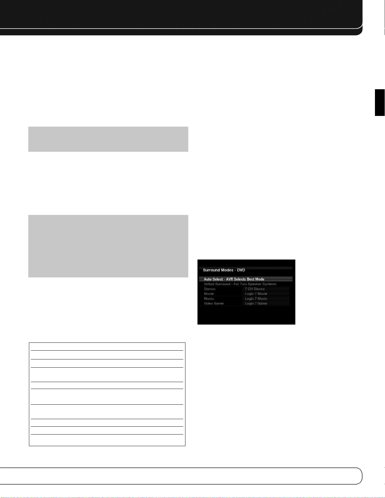
UTILISATION
Pour quitter le Mode Manuel de l’iPod, avec la télécommande de l’AVR en mode
The Bridge, appuyez sur la Touche Menu. Pour retourner à un précédent niveau de
menu, appuyez sur la Touche Retour / Quitter ou la Touche
Aléatoire : Sélectionnez ce paramètre pour la reproduction aléatoire, également
appelée « Shuffle ». Chaque pression sur la touche OK commute le paramètre :
Piste aléatoire, Album aléatoire ou Off pour interrompre la reproduction aléatoire.
Répétition : Sélectionnez ce paramètre pour répéter une piste ou toutes les
pistes de la liste de lecture ou de l’album actuel. Chaque pression sur la touche OK
commute le paramètre : désactivée, répétition d’une piste ou répétition de toutes
les pistes.
REMARQUE : L’application iTunes vous permet d’exclure certaines pistes
du mode Reproduction aléatoire. L’AVR 2600 ne peut pas annuler ce paramètre.
L’AVR prend en charge la reproduction audio de certaines applications disponibles
sur l’iPhone et l’iPod touch. Mettez le système en mode Manuel iPhone ou iPod en
appuyant la touche Menu et en sélectionnant « Photo/Manuel ». Utilisez alors les
commandes de iPhone ou l’iPod touch pour exécuter l’application. Compte tenu de la
multitude d’applications et des nombreux facteurs qui les conditionnent, la reproduction n’est pas garantie. Pendant le défilement, maintenez la touche pour accélérer.
Utilisez la commande Page précédente/suivante de la télécommande pour faire
défiler une page à la fois (pas en mode Manuel).
REMARQUES :
• Les fonctions Lecture et Pause ne sont pas disponibles si des contenus
n’ont pas été sélectionnés pour être reproduits.
• Pour effectuer une recherche sur une piste (pas en mode Manuel), appuyez et
maintenez la touche indiquée. Appuyez une fois sur la touche Piste précédente pour sauter jusqu’au début de la piste actuelle. Appuyez deux fois sur la
touche Piste précédente pour sauter jusqu’au début de la piste précédente.
7.
Lors de la reproduction d’un diaporama, certaines commandes ont des effets différents :
• Pour interrompre momentanément le diaporama, ainsi que toute piste audio
reproduite simultanément, appuyez sur la touche Pause ;
• Pour reprendre un diaporama interrompu momentanément, appuyez sur la
touche Pause. Une pression sur la touche Play démarre la reproduction audio ;
• Pour reproduire une piste audio enregistrée dans l’iPod ou iPhone, réglez les
paramètres de diaporama de l’iPod ou iPhone ;
• Pour sauter à la photo suivante ou précédente de l’iPod ou iPhone, appuyez sur
la touche de navigation Suivant ou Précédent ;
• Il n’est pas possible de sauter à la piste audio suivante ou précédente pendant
un diaporama ;
• Pour rechercher en avant ou en arrière dans une piste audio, appuyez sur la
touche de navigation Recherche avant ou arrière. Si aucune piste audio n’est
reproduite, ces commandes n’auront aucun effet pendant le diaporama.
CHOIX D’UN MODE SURROUND
Le choix d’un mode Surround peut être aussi simple ou aussi sophistiqué que l’est
votre système particulier et vos goûts personnels. N’hésitez pas à essayer pour
trouver quelques modes favoris pour certaines sources ou types de programmes
(la section Fonctions évoluées pour de plus amples informations sur les modes
Surround).
Pour choisir un mode Surround, appuyez sur la touche Modes Surround (façade ou
télécommande). Le menu Modes Surround s’affiche (voir la Figure 29). À l’aide des
touches 1/5 , sélectionnez la catégorie de mode Surround souhaitée : Sélection
automatique, Surround virtuel, Stéréo, Film, Musique ou Jeu vidéo. Appuyez sur la
touche OK pour changer de mode Surround du type d’audio.
FRANÇAIS
MODE MANUEL iPod
Appuyez sur la touche Menu et sélectionnez Photo/Manuel pour passer en mode
Manuel iPod. Cela permet de visualiser des photos enregistrées dans iPhone ou l’iPod.
Le Tableau 6 résume les commandes disponibles quand The Bridge III est en mode
Manuel iPod ou iPhone.
Tableau 6 – Utilisation de The Bridge III en mode Manuel iPod ou
iPhone
Fonction de l’iPod Touche de la télécommande
Lecture Lecture (3)
Pause Pause (II)
Menu Précédent/Quitter ou Flèche
gauche (7)
Sélectionner OK
Sélection prochain écran Flèche vers le haut (
(Scrubber, Pochette, Classification)
Défilement arrière Page précédente ou Flèche
vers le haut (1)
Défilement avant Page suivante ou Flèche vers le (5)
Piste suivante Suivant (
Piste précédente Précédent (
* N’apparaît pas sur l’affichage vidéo connecté à l’AVR.
33
I
77
I )
)
3
)
Figure 29 – Menu Modes Surround
Sélection automatique : Pour les programmes numériques, comme les films
enregistrés avec une bande son Dolby Digital, l’AVR utilise automatiquement le format Surround natif. Pour les programmes analogiques et MIC à 2 canaux, l’AVR
utilise le mode Film, Musique ou Jeu de Logic 7 en fonction de la source.
Surround virtuel : Si le système n’est pourvu que de deux enceintes princi-
pales, le Surround Dolby Virtual peut être utilisé pour créer un champ acoustique
amélioré qui virtualise les enceintes manquantes. Choisissez le mode Wide ou
Reference.
Stéréo : Si vous souhaitez une reproduction à 2 canaux, choisissez le nombre
d’enceintes utilisées pour la reproduction :
• STÉRÉO À 2 CANAUX utilise seulement deux enceintes. Comme décrit en page
35, vous pouvez sélectionner le mode Bypass analogique pour un signal analogique pur si vous utilisez des sources audio analogiques. Désactivez le paramètre Commande de tonalité dans le sous-menu Effets audio et l’AVR s’occupe
du reste.
33
Page 96

UTILISATION
• STÉRÉO À 5 CANAUX délivre le signal du canal gauche dans les enceintes frontales et Surround gauches, le signal du canal droit dans les enceintes droites, et
un signal mono sommé dans l’enceinte centrale.
• STÉRÉO À 7 CANAUX suit le même schéma que STÉRÉO À 5 CANAUX, mais
inclut les enceintes Surround arrière. Ce mode est uniquement disponible
lorsque les enceintes Surround arrière sont présentes et ne sont pas réaffectées
à l’utilisation multizone (voir en page 42 pour de plus amples informations).
Film : Utilisez-le si vous souhaitez un mode Surround pour la reproduction d’un
film : Logic 7 Movie, DTS Neo:6 Cinema ou Dolby Pro Logic II (IIx si le système est
doté de sept enceintes principales).
Musique : Utilisez-le si vous souhaitez un mode Surround pour la reproduction
de musique : Logic 7 Music, DTS Neo:6 Music ou Dolby Pro Logic II (IIx si le système est doté de sept enceintes principales). Le mode Music Dolby Pro Logic II/IIx
vous permet d’accéder à un sous-menu offrant quelques paramètres supplémentaires (voir la section Fonctions évoluées pour de plus amples informations).
Jeu vidéo : Utilisez-le pour choisir un mode Surround pour la reproduction de
jeux : Logic 7 Game ou Dolby Pro Logic II (IIx si le système est doté de sept
enceintes principales) Game.
Après avoir fait votre choix, appuyez sur la touche Précédent/Quitter (voir la section Fonctions évoluées pour de plus amples informations concernant les modes
Surround).
34
Page 97

FONCTIONS ÉVOLUÉES
La plupart des fonctionnalités de l’AVR 2600 sont gérées automatiquement et
n’exigent que très peu d’interventions de votre part. L’AVR 2600 peut être personnalisé pour s’adapter à votre système et à vos goûts. Cette section décrit quelques
réglages plus avancés.
TRAITEMENT AUDIO ET SON SURROUND
Les signaux audio délivrés par les sources sont encodés dans de nombreux formats qui peuvent affecter non seulement la qualité du son mais aussi le nombre
de canaux d’enceintes et le mode Surround. Vous pouvez également choisir
manuellement un mode Surround différent, le cas échéant.
Signaux audio analogiques
Les signaux audio analogiques comprennent généralement deux canaux, gauche
et droite.
L’ AV R 2600 offre trois options pour la reproduction :
Mode Bypass analogique : Le signal à 2 canaux passe directement de
1.
l’entrée à la commande de volume, sans être numérisé ni subir de traitement de
gestion des graves ou de son Surround. Pour choisir le mode Bypass
analogique :
a) Choisissez les entrées audio analogiques correspondant à la source. Si
nécessaire, appuyez sur la touche Info de la télécommande et allez jusqu’à
l’entrée audio à l’aide des touches 5/1 dans le paramètre Source.
b) Désactivez les commandes de tonalité en mettant le paramètre Commande
de tonalité sur désactivé. Appuyez sur la touche Effets audio pour accéder
au paramètre Commande de tonalité.
c) Choisissez le mode stéréo à 2 canaux. Appuyez sur la touche Modes
Surround pour accéder à la ligne STÉRÉO du sous-menu Modes Surround.
Appuyez sur la touche OK pour sélectionner Stéréo à 2 canaux.
Si le paramètre Commande de tonalité est mis sur Désactivé, les enceintes
frontales sont automatiquement mises sur Étendue. Si le paramètre
Commande de tonalité est mis sur Activé et si vous avez saisi un paramètre
numérique pour la séparation des enceintes frontales, ces dernières sont
remises sur Limitée.
REMARQUE : La source The Bridge II délivre un signal audio analogique et
si le mode Stéréo à 2 canaux est choisi, le signal audio est reproduit en mode
Bypass analogique.
2.
Mode DSP Surround Désactivé : Le mode DSP Surround Désactivé
numérise le signal entrant et applique les paramètres de gestion des graves,
comprenant la configuration des enceintes, le décalage et les niveaux de sortie.
Choisissez ce mode si vos enceintes frontales sont des enceintes satellites, de
dimensions réduites et de gamme limitée, et que vous utilisez un subwoofer.
Pour choisir ce mode, utilisez une entrée audio numérique ou mettez le paramètre Commande de tonalité sur Désactivé, et choisissez le mode Stéréo à 2
canaux.
3.
Modes Surround analogiques : L’A V R 2600 peut traiter des signaux
audio à 2 canaux pour produire un son Surround multicanaux, même si l’enregistrement n’est pas fait d’un son Surround encodé. Parmi les modes disponibles on trouve les modes Dolby Pro Logic II/IIx, les modes Dolby Virtual
Speaker, les modes DTS Neo:6, les modes Logic 7 et les modes Stéréo.
Signaux audio numériques
Les signaux audio numériques offrent une capacité supérieure qui permet l’encodage des informations des canaux central et Surround directement dans le signal.
Le résultat est une meilleure qualité de son et une directionnalité saisissante, car
chaque canal est reproduit séparément.
Même si seulement deux canaux sont encodés, le signal numérique permet une
fréquence d'échantillonnage plus élevée qui délivre des détails plus précis. Les
enregistrements à résolution plus élevée offrent un son extraordinaire et sans distorsion, en particulier aux hautes fréquences.
Modes Surround
Le choix du mode Surround dépend du format du signal audio d’entrée ainsi que
des goûts personnels. Le Tableau A13 offre une brève description de chaque mode
et indique les types de signaux d’entrée ou trains de bits numériques avec lesquels le mode peut être utilisé. Des informations supplémentaires concernant les
modes Dolby et DTS sont disponibles sur les sites Web de ces compagnies :
www.dolby.com et www.dtsonline.com.
En cas de doutes, recherchez des informations supplémentaires sur la jaquette de
votre disque quant aux modes Surround disponibles. Les parties non essentielles
du disque, comme les bandes-annonces, les contenus supplémentaires ou le
menu du disque sont uniquement disponibles en mode Dolby Digital 2.0 (à 2
canaux) ou MIC à 2 canaux. Si le titre générique est reproduit et l’afficheur indique
l’un de ces modes Surround, recherchez la partie configuration de langue ou audio
dans le menu du disque. Vérifiez également que la sortie audio de votre lecteur
reproduise le train de bits original et non pas le MIC à 2 canaux.
Interrompez la reproduction et vérifiez le paramètre de sortie du lecteur. Pour tout
signal d’entrée, seuls quelques modes Surround sont disponibles. Même si tous
les modes Surround de l’AVR 2600 ne sont jamais disponibles en même temps, de
nombreux modes sont généralement disponibles pour une entrée donnée.
Les enregistrements numériques multicanaux sont en formats 5.1, 6.1 ou 7.1
canaux. Les canaux constituant un enregistrement à 5.1 canaux sont frontal
gauche, frontal droit, central, Surround gauche, Surround droit et LFE. Le canal LFE
est indiqué « .1 » pour représenter le fait qu’il est limité aux basses fréquences.
Les enregistrements à 6.1 canaux ajoutent un canal arrière Surround unique et les
enregistrements à 7.1 canaux ajoutent les canaux Surround arrière gauche et
Surround arrière droit à la configuration à 5.1 canaux. Les nouveaux formats sont
disponibles en configuration à 7.1 canaux. L’AVR 2600 peut reproduire les nouveaux
formats audio pour offrir une expérience plus excitante de cinéma à domicile.
REMARQUE : Pour utiliser les modes Surround à 6.1 et 7.1 canaux, les
canaux Surround arrière doivent être activés (voir la section Configuration
manuelle des enceintes en page 36 pour de plus amples informations).
Les formats numériques sont Dolby Digital 2.0 (deux canaux seulement), Dolby
Digital 5.1, Dolby Digital EX (6.1), Dolby Digital Plus (7.1), Dolby TrueHD (7.1), DTSHD High-Resolution Audio (7.1), DTS-HD Master Audio (7.1), DTS 5.1, DTS-ES (6.1
Discrete et Matrix), DTS 96/24 (5.1), les modes MIC à 2 canaux en 32 kHz, 44,1
kHz, 48 kHz ou 96 kHz, et MIC multicanaux 5.1 ou 7.1.
Quand un signal numérique est reçu, l’AVR 2600 détecte la méthode d’encodage
et le nombre de canaux qui est affiché brièvement sous forme de trois chiffres
séparés par des barres obliques (par exemple « 3/2/.1 »).
FRANÇAIS
35
Page 98

FONCTIONS ÉVOLUÉES
Le premier chiffre indique le nombre de canaux frontaux du signal :
« 1 » représente un enregistrement monophonique, il s’agit généralement d’un
programme plus ancien qui a été remixé en numérique ou, plus rarement, un
programme moderne pour lequel le réalisateur a choisi un effet spécial ;
« 2 » indique la présence de canaux gauche et droit, mais pas de canal central ;
« 3 » indique que tous les trois canaux frontaux (gauche, droite et central) sont
présents.
Le deuxième chiffre indique si des canaux Surround sont présents :
« 0 » indique qu’aucune information Surround n’est présente ;
« 1 » indique qu’un signal Surround matricé est présent ;
« 2 » indique des canaux Surround gauche et droit discrets ;
« 3 » est utilisé avec les flux de données DTS-ES pour indiquer la présence du
canal Surround arrière discret, en plus des canaux Surround latéraux gauche
et droit ;
« 4 » est utilisé avec les formats numériques à 7.1 canaux pour indiquer la pré-
sence de deux canaux Surround latéraux discrets et de deux canaux
Surround arrière discrets.
Le troisième chiffre est utilisé pour le canal LFE :
« 0 » indique l’absence de canal LFE ;
« .1 » indique la présente d’un canal LFE.
Les signaux à 6.1 canaux, Dolby Digital EX et DTS-ES Matrix et Discrete, intègrent
chacun un fanion destiné à signaler au récepteur de décoder le canal Surround
arrière, indiqué 3/2/.1 EX-ON pour les contenus Dolby Digital EX et 3/3/.1 ES-ON
pour les contenus DTS-ES.
Les signaux Dolby Digital 2.0 peuvent inclure un fanion Dolby Surround qui indique
DS-ON ou DS-OFF si le flux de données à 2 canaux contient seulement des informations stéréo ou un mixage réducteur d’un programme multicanaux pouvant être
décodé par le décodeur Dolby Pro Logic de l’AVR. Par défaut, ces signaux sont
reproduits en mode Dolby Pro Logic IIx film.
Si un signal MIC est reçu, le message MIC et la fréquence d'échantillonnage (32
kHz, 44,1 kHz, 48 kHz ou 96 kHz) s’affiche.
Si deux canaux seulement, gauche et droite, sont présents, les modes Surround
analogiques peuvent être utilisés pour décoder le signal vers les autres canaux. Si
vous préférez un format Surround différent de l’encodage numérique natif du
signal, appuyez sur la touche Modes Surround pour afficher le menu Modes
Surround (voir la Figure 26).
L’option Sélection automatique utilise l’encodage numérique natif du signal, par
exemple Dolby Digital, DTS, Dolby TrueHD ou DTS-HD Master Audio. Pour les
contenus à 2 canaux, l’AVR passe par défaut en mode Logic 7 Movie. Si vous préférez un mode Surround différent, choisissez la catégorie de mode Surround suivante : Surround virtuel, Stéréo, Film, Musique ou Jeu vidéo. Appuyez sur la touche
OK pour changer de mode.
Chaque catégorie définit un mode Surround par défaut :
Surround virtuel : Harman Virtual Speaker
•
Stéréo : stéréo à 7 canaux
•
• Film : Logic 7 Movie
• Musique : Logic 7 Music
• Jeu vidéo : Logic 7 Game
Vous pouvez sélectionner un mode différent. Le choix des modes Surround dépend
du nombre d’enceintes de votre système.
Surround virtuel : Harman Virtual Speaker
•
• Stéréo : stéréo à 2 canaux, stéréo à 5 canaux ou stéréo à 7 canaux
• Film : Logic 7 Movie, DTS Neo:6 Cinema, Dolby Pro Logic II Movie, Dolby Pro
Logic IIx Movie
• Musique : Logic 7 Movie, DTS Neo:6 Cinema, Dolby Pro Logic II Movie, Dolby
Pro Logic IIx Movie
• Jeu vidéo : Logic 7 Game, Dolby Pro Logic II Game, Dolby Pro Logic IIx Game
Après avoir programmé le mode Surround pour chaque type de signal audio,
sélectionnez la ligne du menu Modes Surround pour annuler le choix automatique
de mode Surround de l’AVR. L’AVR utilisera le même mode Surround la prochaine
fois que cette source est choisie.
Veuillez consultez le Tableau A13 de l’annexe pour de plus amples informations
concernant les modes Surround disponibles pour les différents flux de données.
Paramètres Dolby Surround
Quelques paramètres supplémentaires sont disponibles pour les modes Dolby.
Lorsque les modes Dolby Pro Logic II ou IIx Music ont été choisis, choisissez le
sous-menu Édition pour ajuster les paramètres de Largeur de l’enceinte centrale,
Dimensions et Panorama (voir la Figure 30).
Figure 30 – Paramètres des modes Dolby Pro Logic II/IIx Music
Largeur de l’enceinte centrale : Ce paramètre détermine comment les trois
enceintes frontales reproduisent les voix. Un chiffre élevé (jusqu’à 7) concentre étroitement les informations vocales sur le canal central. Des chiffres plus faibles élargissent la reproduction des voix. Ajustez ce paramètre à l’aide des touches
Dimensions : Ce paramètre affecte la profondeur de la présentation Surround et
vous permet de « déplacer » le son vers l’avant oui l’arrière de la salle. La valeur
« 0 » du paramètre par défaut est neutre. La valeur « F-3 » déplace le son vers
l’avant de la salle et la valeur « R-3 » déplace le son vers l’arrière. Ajustez ce paramètre à l’aide des touches
Panorama : Le mode Panorama étant sur ACTIVÉ, une partie du son des
enceintes frontales est déplacé vers les enceintes Surround pour créer un effet «
panoramique » enveloppant. Chaque pression sur la touche OK active ou désactive
le paramètre.
7/3 .
7/3.
CONFIGURATION MANUELLE DES ENCEINTES
L’ AV R 2600 est flexible et peut être configuré pour la plupart des enceintes ainsi
que de manière à compenser les caractéristiques acoustiques de votre salle.
Le processus EzSet/EQ détecte automatiquement les possibilités de chaque
enceinte et optimise les performances de l’AVR 2600.
Si vous ne pouvez pas effectuer un réglage EzSet/EQ ou si vous souhaitez effectuer des réglages plus poussés, utilisez les menus Configuration manuelle des
enceintes affichés à l’écran.
36
Page 99

FONCTIONS ÉVOLUÉES
Avant de commencer, placez vos enceintes comme indiqué dans la section
Disposition des enceintes et raccordez-les à l’AVR. Consultez la spécification de
bande passante dans le manuel du propriétaire des enceintes ou le site Web du
fabricant. Même si vous pouvez régler les niveaux de sortie « à l’oreille », un calibreur de niveau de pression acoustique acheté dans le magasin d’électronique de
votre quartier offre une précision supérieure.
Consignez vos paramètres de configuration dans les Tableaux A3 à A12 de l’annexe pour une nouvelle saisie après la réinitialisation du système ou si l’interrupteur d'alimentation principal de l’AVR est coupé ou si son cordon secteur est
débranché pendant plus de quatre semaines.
REMARQUE : Pour utiliser les menus de configuration des enceintes de
l’AVR, sélectionnez une résolution de sortie vidéo de 720p ou supérieure pour
visualiser les graphiques qui simplifient la configuration.
ÉTAPE UN – Détermination de la fréquence de séparation des enceintes
Sans utiliser le processus EzSet/EQ, l’AVR 2600 ne peut pas détecter combien
d’enceintes vous y avez connectées, il ne peut non plus déterminer leurs possibilités. Consultez les spécifications techniques des enceintes et situez leur réponse
en fréquence, indiquée généralement comme une gamme, 100 Hz – 20 kHz (±3
dB) par exemple. Consignez la plus basse fréquence que chacune de vos
enceintes principales peut reproduire (100 Hz dans l’exemple) comme la séparation du Tableau A3 de l’annexe. Elle est différente de la fréquence de séparation
indiquée dans les spécifications des enceintes. Pour le subwoofer, consignez la
taille du transducteur.
La gestion des graves du récepteur détermine quelles enceintes vont être utilisées
pour reproduire la partie basse fréquence (graves) du programme source. Les
petites enceintes satellites reproduiraient très mal les notes les plus graves et
celles-ci pourraient même endommager ces enceintes. Inversement, le subwoofer
risque de ne pas pouvoir reproduire toutes les notes les plus aigues.
Grâce à une gestion appropriée des graves, l’AVR 2600 divise le signal source à un
point de séparation. Toutes les fréquences supérieures au point de séparation sont
reproduites par les enceintes satellites et toutes les fréquences inférieures au
point de séparation sont reproduites par le subwoofer. Chaque enceinte de votre
système travaille au mieux et offre une expérience acoustique agréable.
ÉTAPE TROIS – Menu Configuration
manuelle
Vous êtes maintenant prêt à programmer le récepteur. Asseyez-vous dans la position d’écoute habituelle et rendez la salle le plus silencieuse possible.
Allumez le récepteur et l’écran vidéo, puis appuyez sur la touche Paramètres de
l’AVR pour afficher le système de menus. À l’aide de la touche 5, déplacez le cur-
seur jusqu’à la ligne Configuration des enceintes puis appuyez sur la touche OK
pour afficher le menu Configuration des enceintes (voir la Figure 21).
Pour modifier légèrement les résultats de EzSet/EQ ou pour configurer l’AVR à partir
de zéro, sélectionnez Configuration de la position d’écoute 1 ou Configuration de la
position d’écoute 2. Un écran similaire à celui illustré par la Figure 31 s’affiche.
Figure 31 – Menu Configuration de la position des enceintes
REMARQUE : Tous les sous-menus de configuration des enceintes com-
prennent l’option Précédent, comme illustré au bas de la Figure 31. Pour
enregistrer les paramètres actuels, sélectionnez l’option Précédent.
Pour reconfigurer les enceintes depuis zéro, sélectionnez l’option Réinitialisation. Pour
de meilleurs résultats, ajustez les sous-menus dans l’ordre suivant : Nombre d’enceintes, Séparation (Dimensions), Mode subwoofer, Distance et Réglage du niveau.
Nombre d’enceintes
Déplacez le curseur jusqu’à la ligne Nombre d’enceintes puis appuyez sur la
touche OK (voir la Figure 32).
FRANÇAIS
ÉTAPE DEUX – Mesure des distances
entre les enceintes
Idéalement, toutes vos enceintes devraient être situées sur un cercle dont le
centre est la position d’écoute. Cependant, il est possible que vous deviez placer
certaines enceintes un peu plus loin de la position d’écoute que d’autres. Les sons
qui sont supposés arriver simultanément depuis les différentes enceintes peuvent
être décalés en raison des temps d’arrivée différents.
Utilisez le réglage du décalage de l’AVR pour compenser les emplacements réels
des enceintes.
Mesurez la distance entre chaque enceinte et la position d’écoute et consignez-la
dans le Tableau A4 de l’annexe. Même si tous vos enceintes sont à la même distance de la position d’écoute, saisissez les distances jusqu’aux enceintes comme
décrit à l’étape trois.
Figure 32 – Menu Nombre d’enceintes
Donnez le paramètre correct à chaque groupe d’enceintes : ACTIVÉES si les
enceintes sont présentes dans le système, DÉSACTIVÉES pour les positions
dépourvues d’enceintes. Les enceintes frontales gauche et droite sont toujours
ACTIVÉES et ne peuvent pas être désactivées. Tous les changements sont reflétés
dans le nombre total d’enceintes affiché au haut de l’écran.
Le paramètre pour les enceintes Surround arrière comprend une troisième option :
Zone 2. L’AVR 2600 peut fonctionner en multizone, permettant ainsi de placer une
paire d’enceintes dans une autre salle. Les canaux amplificateurs Surround arrière
affectables de l’AVR 2600 rendre le fonctionnement multizone plus facile que
jamais car un amplificateur de puissance externe n’est pas nécessaire.
Sélectionnez l’option Zone 2 sur cette ligne et connectez les sorties enceintes
Surround arrière aux enceintes situées dans la salle distante.
37
Page 100
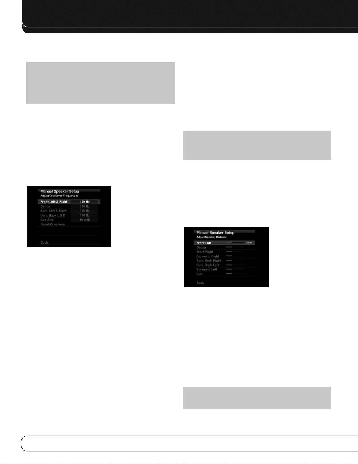
FONCTIONS ÉVOLUÉES
La salle principale est alors configurée automatiquement pour 5.1 canaux au maximum (voir la section Fonctionnement Multizone pour de plus amples informations).
REMARQUE : Si les enceintes Surround arrière sont affectées à la
« Zone 2 », elles ne sont pas configurées pendant le processus EzSet/EQ.
Pour utiliser les enceintes dans la zone d’écoute principale, configurez-les sur
« Activées » et exécutez le processus EzSet/EQ II pour un système à 7.1
canaux. Si les enceintes sont utilisées uniquement en fonctionnement multizone, configurez-les manuellement, comme expliqué ci-dessous.
Les paramètres de ce menu affectent le reste du processus de configuration des
enceintes ainsi que la disponibilité de plusieurs modes Surround à tout moment.
Après avoir fini, choisissez l’option Précédent ou appuyez sur la touche
Précédent/Quitter.
Menu Réglage des fréquences de
séparation
Après avoir programmé le nombre d’enceintes, l’AVR revient au menu
Configuration de la position des enceintes (voir la Figure 31). Naviguez jusqu’à la
ligne Séparation (Dimensions) et appuyez sur la touche OK pour afficher le menu
Réglage des fréquences de séparation (voir la Figure 33).
• Si vous avez défini Étendue pour les enceintes frontales, sélectionnez l’un des
trois paramètres pour le subwoofer.
• G/D+LFE : Ce paramètre envoie toutes les informations basse fréquence
au subwoofer, c’est-à-dire les informations qui sont normalement reproduites
par les enceintes frontales gauche et droite ainsi que les informations du
canal LFE spécial (low-frequency effects).
• Désactivé : Sélectionnez ce paramètre si aucun subwoofer n’est utilisé.
Toutes les informations basse fréquence sont envoyées au enceintes frontales gauche et droite.
• LFE : Cette valeur fait reproduire les informations basse fréquence conte-
nues dans les canaux gauche et droite du programme par les enceintes frontales et envoie uniquement le canal LFE au subwoofer.
REMARQUE : Si vous utilisez un système d’enceintes Harman Kardon
série HKTS, sélectionnez la fréquence de séparation numérique appropriée
pour le groupe d’enceintes principal et le subwoofer est automatiquement
mis sur LFE.
Menu Réglage de la distance des enceintes
Si les enceintes sont placées à des distances différentes des positions d’écoute, le
son peut perdre de la précision car certains sons sont perçus plus tôt ou plus tard.
Même si vous placez toutes vos enceintes à la même distance de la position
d’écoute, ne sautez pas ce menu.
Dans le menu Configuration de la position des enceintes, déplacez le curseur jusqu’à la ligne Distance puis appuyez sur la touche OK pour afficher le menu
Réglage de la distance des enceintes (voir la Figure 34).
Figure 33 – Menu Réglage des fréquences de séparation
L’AVR affiche uniquement les groupes d’enceintes programmés dans le menu
Nombre d’enceintes.
Consultez le Tableau A3 pour la séparation de chaque enceinte. Pour les enceintes
principales, il s’agit de la fréquence la plus basse que l’enceinte reproduit correctement.
Pour chaque enceinte principale, sélectionnez une des sept fréquences de séparation : 40 Hz, 60 Hz, 80 Hz, 100 Hz, 120 Hz, 150 Hz ou 200 Hz. Si la fréquence de
séparation est inférieure à 40 Hz, sélectionnez la première option, « Étendue ». Ce
paramètre ne représente pas la taille matérielle de l’enceinte mais sa réponse en
fréquence qui est aussi appelée « gamme étendue ».
Spécifiez la taille du transducteur du subwoofer : 8, 10, 12 ou 15 pouces. L’AVR définit toujours la séparation du subwoofer à 100 Hz, mais il utilise la taille de son transducteur pour l’égalisation. Consignez les paramètres dans le Tableau A3 de l’annexe.
Après avoir fini de saisir les paramètres, choisissez l’option Précédent ou appuyez
sur la touche Précédent/Quitter.
Mode Subwoofer
Déplacez le curseur jusqu’à la ligne Mode Subwoofer. Ce paramètre dépend de la
manière dont vous avez programmé les enceintes frontales gauche et droite.
• Si vous avez défini une fréquence de séparation numérique pour les enceintes
frontales, le paramètre Subwoofer est toujours LFE. Toutes les informations
basse fréquence sont toujours envoyées au subwoofer. Si vous ne possédez pas
de subwoofer, achetez des enceintes à gamme étendue ou ajoutez un subwoofer
le plus tôt possible.
Figure 34 – Menu Réglage de la distance des enceintes
Saisissez la distance entre chaque enceinte et la position d’écoute, mesurée à
l’étape deux, Mesure des distances entre les enceintes, et consignée dans le
Tableau A4 de l’annexe (voir en page 37).
Les unités de mesure par défaut sont des pieds. Pour changer les unités en
mètres, revenez au menu principal de l’AVR. Sélectionnez le menu Paramètres du
système, puis allez vers le bas jusqu’à la section Paramètres généraux de l’AVR et
sélectionnez la ligne Unités de mesure. Appuyez sur la touche OK pour modifier le
paramètre.
Sélectionnez une enceinte, puis modifiez la mesure à l’aide des touches 7/3. Les
valeurs varient entre 0 et 30 pieds, la valeur par défaut étant 12 pieds pour toutes
les enceintes à l’exception des enceintes Surround gauche et droite, pour lesquelles la valeur par défaut est 10 pieds.
REMARQUE : Si les canaux Surround arrière sont affectés au système
multizone, vous ne pouvez pas ajuster leurs paramètres de décalage.
38
 Loading...