

Page 1
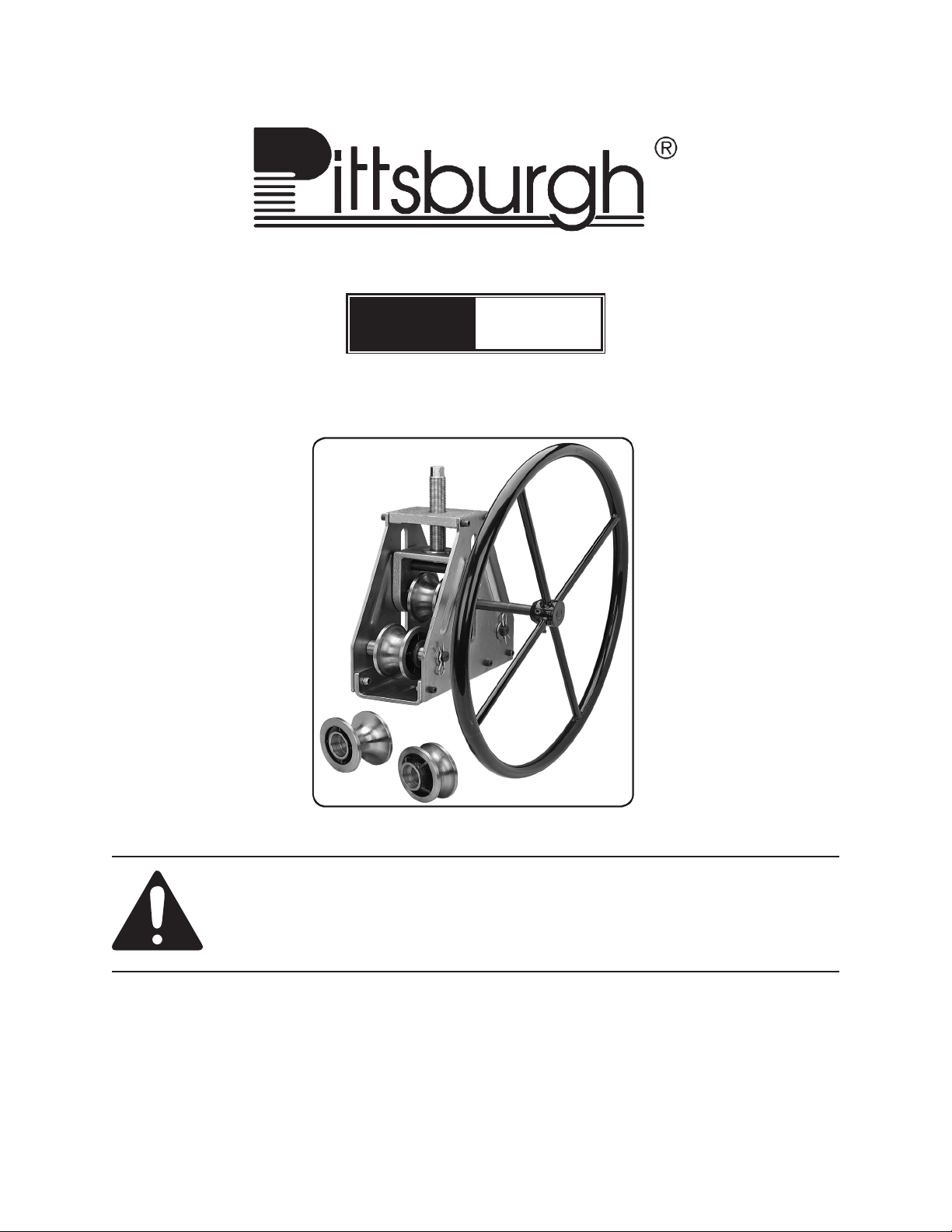
TUBING ROLLER
Model
99736
ASSEMBLY, OPERATING AND MAINTENANCE
INSTRUCTIONS
Visit our website at: http://www.harborfreight.com
Read this material before using this product.
Failure to do so can result in serious injury.
SAVE THIS MANUAL.
Copyright© 2008 by Harbor Freight Tools®. All rights reserved. No portion of this manual or any artwork
contained herein may be reproduced in any shape or form without the express written consent of
Harbor Freight Tools. Diagrams within this manual may not be drawn proportionally. Due to continuing
improvements, actual product may differ slightly from the product described herein. Tools required for
assembly and service may not be included.
For technical questions or replacement parts, please call 1-800-444-3353.
Revised Manual 11h
Page 2
SAVE THIS MANUAL
Keep this manual for the safety
warnings and precautions, assembly,
operating, inspection, maintenance and
cleaning procedures. Write the product’s
serial number in the back of the manual
near the assembly diagram (or month
and year of purchase if product has no
number). Keep this manual and the
receipt in a safe and dry place for future
reference.
IMPORTANT SAFETY
INSTRUCTIONS
In this manual, on the labeling,
and all other information
provided with this product:
This is the safety alert
symbol. It is used to alert
you to potential personal
injury hazards. Obey all
safety messages that
follow this symbol to avoid
possible injury or death.
DANGER indicates
a hazardous
situation which, if
not avoided, will result in
death or serious injury.
WARNING
indicates a
hazardous
situation which, if not
avoided, could result in death
or serious injury.
CAUTION, used
with the safety
alert symbol,
indicates a hazardous
situation which, if not
avoided, could result in minor
or moderate injury.
NOTICE is used to
address practices
not related to
personal injury.
CAUTION, without
the safety alert
symbol, is used to
address practices not related
to personal injury.
READ ALL INSTRUCTIONS
Personal Safety
Dress Properly - Do not wear loose 1.
clothing or jewelry. They can be
caught in moving parts. Use of rubber
gloves and substantial footwear
is recommended when working
outdoors. Wear protective hair
covering to contain long hair.
2. Wear ANSI-approved safety
goggles and heavy-duty
work gloves. Use face or
dust mask if operation is
dusty.
Do not Overreach - Keep proper 3.
footing and balance at all times.
Stay Alert - Watch what you are 4.
doing. Use common sense. Do not
operate Tool when you are tired.
Page 2SKU 99736 For technical questions, please call 1-800-444-3353.
Page 3
5. Keep hands and feet away
from bending area.
Tubing Roller Use and Care
qualied technician unless indicated
elsewhere in this manual.
Never attempt to bend any tube 8.
which is pressurized or contains wire
or any other objects inside.
Keep Children Away - All visitors 1.
should be kept at a distance from
work area.
When servicing use only identical 2.
replacement parts.
Use Right Tool - Do not use tool for 3.
any job except that for which it is
intended.
Do not Force Tool - It will do the 4.
job better and with less likelihood
of injury at the rate for which it was
designed.
Store Idle Tools Indoors - When not in 5.
use, Tools should be stored indoors
in dry, and high or locked-up place out of reach of children.
Maintain Tool With Care - Keep 6.
tool maintained to reduce the risk
of injury. Follow instructions for
lubricating and changing accessories.
Keep handles dry, clean, and free
from oil and grease.
Do not attempt to bend tubes that are 9.
larger than 2” in diameter.
Do not use re or ame during 10.
bending.
Do not attempt to bend wood or 11.
plastic rods or tubes. Brittle materials
such as these can break without
warning, causing injury or damage.
SAVE THESE
INSTRUCTIONS.
Specications
Materials Application
Rollers Included
EMT* Conduit Sizes 3/4”, 1-1/4”, 2”
*Electrical Metallic Tubing
** For fabricating exhaust systems and roll bars.
UNPACKING
Steel, Copper and
Aluminum Tubing **
1” , 1-1/2”, 2” O.D.
Tubing
Check Damaged Parts - Before 7.
further use of the Tool, a guard or
other part that is damaged should be
carefully checked to determine that
it will operate properly and perform
its intended function. Check for
alignment of moving parts, binding
of moving parts, breakage of parts,
mounting, and any other condition
that may affect its operation. A guard
or other part that is damaged should
be properly repaired or replaced by a
When unpacking, check to make sure
that the item is intact and undamaged. If
any parts are missing or broken, please call
Harbor Freight Tools at the number shown
on the cover of this manual as soon as
possible.
REV 08k, 09b, 10g
Page 3SKU 99736 For technical questions, please call 1-800-444-3353.
Page 4

SET UP INSTRUCTIONS
Read the ENTIRE
IMPORTANT SAFETY
INSTRUCTIONS section at the
beginning of this manual
including all text under
subheadings therein before set
up or use of this product.
Note: For additional information regarding
the parts listed in the following pages,
refer to the Assembly Diagram near
the end of this manual.
Assembly
Shafts out of the Rollers (12 and 20)
and Bushings (10).
Select the correct Rollers to match 4.
the diameter tubing you will be
bending. If your tubing does not
match the exact size of the available
Rollers, use the Roller size just larger
in diameter than the tubing material.
Install the Rollers by inserting the 5.
Shafts (4 and 23), being sure the
Washers (5) and Bushings (10)
are in place. Refer to the Assembly
Diagram at the end of this manual for
correct assembly. Fix the Shafts in
place using the “R” Pins (22). Note:
Make sure to attach one Bearing (11)
to each side of Rollers(12).
Mount the Turning Wheel (2) onto the 1.
Axle (3). Secure the Wheel in place
using two Screws (1). Be sure Wheel
and Axle turn freely, then tighten
screws securely.
This tool may be bench mounted, if 2.
desired. To bench mount, choose an
appropriate work bench for mounting.
The workbench must be solid, level
and strong enough to support the
weight of the tool, the work material,
and pressure applied to the tool
during bending. Use the U-Shaped
Base (8) as a template to mark
the bench top. Drill two holes for
mounting bolts (not included), being
careful not to drill into any hidden
electric or other utility lines. Mount
the Base using bolts (not included),
tighten securely.
Before use, the correct size Rollers 3.
must be installed. Pull the “R” Pins
(22) from the Shafts (4 and 23),
Remove the Washers (5) and pull the
Functions
This tool is intended to bend mild 1.
steel, copper and aluminum tubing.
It can be used for bending exhaust
pipe, water pipe and electrical conduit. Do not bend plastic or PVC pipe
with this tool.
Available Accessories/Attach-
ments
Use of any acces-
sory or attachment
other than those
listed below may increase the
risk of serious injury.
This Tool includes three sets of Roll-1.
ers: small, medium and large.
The minimum practical bend radius 2.
for any tube varies with the diameter
and wall thickness of the tube. Extra
heavy tubes can be bent to a smaller
radius than thinner wall tubes of the
same diameter. In general, tubes of
REV 09c
Page 4SKU 99736 For technical questions, please call 1-800-444-3353.
Page 5

standard wall thickness should not be
bent to a radius less than 5 to 6 times
the nominal tube diameter.
Tubing Diameter Minimum Radius
1” 5”
1-1/2” 7-1/2”
2” 10”
Attempting to make a bend of too 3.
small radius will result in the tube
attening, folding or rupturing.
OPERATING INSTRUCTIONS
Using a piece of test material, turn 4.
the Adjustment Screw (15) clockwise
to lower the Middle Roller (20)
slightly. Turn the Turning Wheel (2)
slightly to roll the tubing between the
Rollers. You will begin to bend the
tubing.
Continue to alternately lower the 5.
Adjustment Screw (15) and turn the
Wheel (2) until the desired bend
radius is achieved.
Remove the piece of test material 6.
and insert the work material between
the Middle Roller (20) and either of
the Rollers (12). Turn the Wheel (2)
to roll the tubing through the Rollers,
bending it as desired.
Read the ENTIRE
IMPORTANT SAFETY
INFORMATION section at the
beginning of this manual
including all text under
subheadings therein before set
up or use of this product.
Before operating the Tubing Roller, 1.
put on ANSI-approved safety goggles
and heavy duty work gloves.
2. Keep hands away from the
Rollers (12 and 20) during
operation. Severe pinch and
crushing hazard exists at
these areas during operation.
Using a Hex Wrench (not included) 3.
turn the Adjustment Screw (15)
counterclockwise to raise the Middle
Roller (20). Raise it enough that
the work material can be inserted
between either of the Rollers (12) and
the Middle Roller (20).
To remove the work material, you can 7.
reverse direction on the Wheel (2) or
loosen the Adjustment Screw (15).
Simple or complex bends can be 8.
made by careful use of this basic but
effective bending tool. For example,
if an “S” curve is needed, make the
rst half of the bend, then rotate the
tubing and continue the bend to make
the second half of the “S”.
Changing the Rollers
NOTE: Please refer to the Assembly
diagram at the back of this manual for
correct installation of Rollers.
You must change rollers to suit tubing 1.
of different diameters. Select the
roller size that is closest to the size
tubing you will bend.
To remove rollers, remove one “R” 2.
Pin (22) from the end of each of the
Black Shafts (4) and the Middle Shaft
REV 08k, 09c
Page 5SKU 99736 For technical questions, please call 1-800-444-3353.
Page 6

(23). Slide the Shafts out, retaining
the Washers (5) and Bushings (10).
Store this tool in a dry location away 4.
from moisture or corrosive materials.
Re-install the Black Shafts (4) 3.
and the Middle Shaft (23) with the
selected Rollers, Washers (5) and
Bushings (10) in place.
Re-install the “R” Pins (22).4.
MAINTENANCE AND
SERVICING
Procedures not
specically explained in this
manual must be performed only
by a qualied technician.
TO PREVENT
SERIOUS INJURY FROM
TOOL FAILURE:
Do not use damaged
equipment. If abnormal noise
or binding occurs, have the
problem corrected before
further use.
Cleaning, Maintenance, and
Lubrication
BEFORE EACH USE,1. inspect the
general condition of the Tool. Check
for loose screws, misalignment or
binding of moving parts, cracked or
broken parts and any other condition
that may affect its safe operation.
Part # Description QTY.
1 Screw M6 x 25 2
2 Turning Wheel 1
3 Axle 1
4 Shaft (Black) 2
5 Washer 6
6 Screw M8 x 25 8
7 Side Plate 2
8 U-Shaped Base 1
9 Lock Nut m8 8
10 Bushing 4
11 Bearing 6
12a Roller 3/4” EMT Size 2
12b Roller 1-1/4” EMT Size 2
12c Roller 2” EMT Size 2
13 Screw m8 x 20 4
14 Lock Washer 4
15 Adjustment Screw 1
16 Top Block 1
17 Flat Washer 2
18 “U” Bracket 1
19 Snap Ring 1
20a Middle Roller 1
20b Middle Roller 1
20c Middle Roller 1
21 Screw M 6 x 12 3
22 “R” Pins 6
23 Shaft 1
AFTER USE,2. clean external surfaces
of the Tool with clean, moist cloth.
Occasionally coat bare metal 3.
components with a light coating of oil
to prevent corrosion.
REV 08k
Page 6SKU 99736 For technical questions, please call 1-800-444-3353.
Page 7

ASSEMBLY DIAGRAM
Page 7SKU 99736 For technical questions, please call 1-800-444-3353.
Page 8

90 DAY WARRANTY
Harbor Freight Tools Co. makes every effort to assure that its products meet high quality and durability standards, and warrants to the original purchaser that this product is
free from defects in materials and workmanship for the period of 90 days from the date
of purchase. This warranty does not apply to damage due directly or indirectly, to misuse, abuse, negligence or accidents, repairs or alterations outside our facilities, criminal
activity, improper installation, normal wear and tear, or to lack of maintenance. We shall
in no event be liable for death, injuries to persons or property, or for incidental, contingent, special or consequential damages arising from the use of our product. Some states
do not allow the exclusion or limitation of incidental or consequential damages, so the
above limitation of exclusion may not apply to you. This warranty is expressly in lieu of
all other warranties, express or implied, including the warranties of merchantability and
tness.
To take advantage of this warranty, the product or part must be returned to us with transportation charges prepaid. Proof of purchase date and an explanation of the complaint
must accompany the merchandise. If our inspection veries the defect, we will either
repair or replace the product at our election or we may elect to refund the purchase price
if we cannot readily and quickly provide you with a replacement. We will return repaired
products at our expense, but if we determine there is no defect, or that the defect resulted from causes not within the scope of our warranty, then you must bear the cost of
returning the product.
This warranty gives you specic legal rights and you may also have other rights which
vary from state to state.
3491 Mission Oaks Blvd. • PO Box 6009 • Camarillo, CA 93011 • (800) 444-3353
PLEASE READ THE FOLLOWING CAREFULLY
THE MANUFACTURER AND/OR DISTRIBUTOR HAS PROVIDED THE PARTS LIST AND ASSEMBLY DIAGRAM IN
THIS MANUAL AS A REFERENCE TOOL ONLY. NEITHER THE MANUFACTURER OR DISTRIBUTOR MAKES ANY
REPRESENTATION OR WARRANTY OF ANY KIND TO THE BUYER THAT HE OR SHE IS QUALIFIED TO MAKE ANY
REPAIRS TO THE PRODUCT, OR THAT HE OR SHE IS QUALIFIED TO REPLACE ANY PARTS OF THE PRODUCT.
IN FACT, THE MANUFACTURER AND/OR DISTRIBUTOR EXPRESSLY STATES THAT ALL REPAIRS AND PARTS
REPLACEMENTS SHOULD BE UNDERTAKEN BY CERTIFIED AND LICENSED TECHNICIANS, AND NOT BY THE
BUYER. THE BUYER ASSUMES ALL RISK AND LIABILITY ARISING OUT OF HIS OR HER REPAIRS TO THE
ORIGINAL PRODUCT OR REPLACEMENT PARTS THERETO, OR ARISING OUT OF HIS OR HER INSTALLATION
OF REPLACEMENT PARTS THERETO.
Record Product’s Serial Number Here:
Note: If product has no serial number, record month and year of purchase instead.
Note: Some parts are listed and shown for illustration purposes only, and are not
available individually as replacement parts.
REV 11h
Page 8SKU 99736 For technical questions, please call 1-800-444-3353.
 Loading...