

Page 1
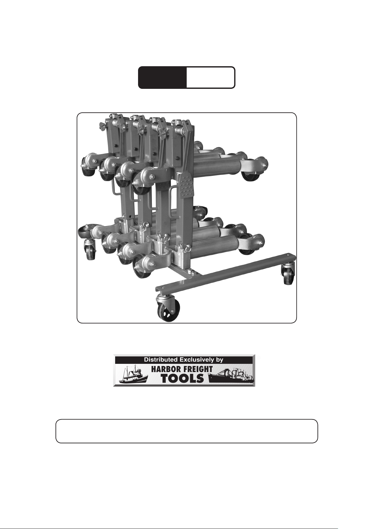
WHEEL DOLLY STAND/HOLDER
Model
95409
®
ASSEMBLY AND OPERATION INSTRUCTIONS
Wheel dollies (sku 94682) sold separately.
Due to continuing improvements, actual product may differ slightly from the product described herein.
3491 Mission Oaks Blvd., Camarillo, CA 93011
Visit our website at: http://www.harborfreight.com
TO PREVENT SERIOUS INJURY, READ AND UNDERSTAND
ALL WARNINGS AND INSTRUCTIONS BEFORE USE.
Copyright© 2006 by Harbor Freight Tools®. All rights reserved. No portion of
this manual or any artwork contained herein may be reproduced in any shape
or form without the express written consent of Harbor Freight Tools.
For technical questions or replacement parts, please call 1-800-444-3353.
For technical questions, please call 1-800-444-3353.
Page 1SKU 95409
Page 2

SPECIFICATIONS
Material Formed and welded flat steel stock
Weight Capacity 300 lb.
Ground Clearance 5-1/8” H
Swivel Casters Black poly-plastic w/ zinc plated steel frames.
Overall Dimensions 24-7/8” L X 31-7/8” W X 9-9/16” H
Wheel Dimensions 5” Dia. X 1” W
Carrying Handle Dimensions 2” L X 5-3/16” W X 3/8” T
Wheel Dolly Holders’ Dimensions 5/16” L X 1-5/8” W X 3-5/8” T
Net Weight 21.4 lb.
SAVE THIS MANUAL
You will need this manual for the safety warnings and precautions, assembly,
operating, inspection, maintenance and cleaning procedures, parts and assembly diagram. Keep your invoice with this manual. Write the invoice number on the inside of the
front cover. Write the product serial number in the back of the manual near the assembly
diagram, or write the month and year of purchase if the product has no serial number.
Keep this manual and invoice in a safe and dry place for future reference.
1.
2.
3.
4.
5.
6.
SAFETY WARNINGS AND PRECAUTIONS
Wear proper clothing. Always use ANSI-approved safety impact goggles when
assembling or using this Wheel Dolly Stand/Holder. Wear long sleeved shirts,
long pants and steel-toed boots.
Keep work area clean and well lighted. A dim and/or cluttered work area in-
vites personal injury.
Keep children away from work areas. Children can be a distraction and should
be supervised by an adult when near the work area. Never allow children to
ride on, or play with this product.
Check for damaged parts. Before using this Wheel Dolly Stand/Holder, carefully
check for any parts that may be missing or damaged and any other conditions
that may affect the operation of this tool. Replace or repair damaged and worn
parts immediately using only a qualified repair facility.
Always use the proper tools. This Wheel Dolly Stand/Holder was designed
for a specific task. Do not alter this tool, or use it for a purpose to which it was
not intended.
Work safely. Do not use this Wheel Dolly Stand/Holder if under the influence
of alcohol or prescription drugs. Doing so could cause damage to the tool or
personal injury.
7.
Never exceed the maximum weight capacity of 300 lb. BE AWARE OF DY-
NAMIC LOADING: If the Wheel Dolly Stand/Holder is dropped while loaded it
For technical questions, please call 1-800-444-3353.
Page 2SKU 95409
Page 3

could briefly create an excess load which may result in damage to the tool or
personal injury.
8.
9.
10.
Note: The warnings, cautions, and instructions discussed in this instruction manual
Only use on a flat, level and stable surface able to withstand the weight of
the Wheel Dolly Stand/Holder and it maximum weight capacity of 300 lb.
Use this tool correctly. Do not at any time use this tool for transporting people
or animals.
Do not use the Wheel Dolly Stand/Holder if it is damaged or broken. All
repairs should only be completed by a qualified repair facility.
cannot cover all possible conditions and situations that may occur. It must be
understood by the operator that common sense and caution are factors that
cannot be built into this product but must be supplied by the operator.
UNPACKING
When unpacking, check to be sure that all parts listed on page 5 of this manual
are included. If any parts are missing or broken, please call Harbor Freight Tools at
1-800-444-3353 as soon as possible.
For technical questions, please call 1-800-444-3353.
Page 3SKU 95409
Page 4

ASSEMBLY
Figure 1
1.
2.
Attach Caster Assembly (1) to Left Main Beam (2) using Flat Washer (3), Lock
Washer (4) and Nut (5). See Figure 1.
Follow the same procedure with the remaining three Caster Assemblies (1) and
the Right Main Beam (8).
3.
Figure 2
Attach Cross Beam (7) to Right Main Beam (8) and Left Main Beam (2) using
Bolt (6), Flat Washer (3), Lock Washer (4) and Nut (5). See Figure 2.
For technical questions, please call 1-800-444-3353.
Page 4SKU 95409
Page 5

OPERATION
1.
2.
Place one Wheel Dolly (sku 94682, sold separately) on each of the four hold-
ers on the Cross Beam (7). The metal part of each dolly should slide over one
holder.
Store stand and dollies in a dry, level place where they will not present a tripping
hazard.
PARTS LIST
Part Description Q’ty
1 Caster Assembly 4
2 Left Main Beam 1
3 Flat Washer M12 8
4 Lock Washer M12 8
PLEASE READ THE FOLLOWING CAREFULLY
THE MANUFACTURER AND/OR DISTRIBUTOR HAS PROVIDED THE PARTS LIST AND
ASSEMBLY DIAGRAM IN THIS MANUAL AS A REFERENCE TOOL ONLY. NEITHER THE
MANUFACTURER OR DISTRIBUTOR MAKES ANY REPRESENTATION OR WARRANTY OF
ANY KIND TO THE BUYER THAT HE OR SHE IS QUALIFIED TO MAKE ANY REPAIRS TO THE
PRODUCT, OR THAT HE OR SHE IS QUALIFIED TO REPLACE ANY PARTS OF THE PRODUCT. IN FACT, THE MANUFACTURER AND/OR DISTRIBUTOR EXPRESSLY STATES THAT
ALL REPAIRS AND PARTS REPLACEMENTS SHOULD BE UNDERTAKEN BY CERTIFIED AND
LICENSED TECHNICIANS, AND NOT BY THE BUYER. THE BUYER ASSUMES ALL RISK
AND LIABILITY ARISING OUT OF HIS OR HER REPAIRS TO THE ORIGINAL PRODUCT OR
REPLACEMENT PARTS THERETO, OR ARISING OUT OF HIS OR HER INSTALLATION OF
REPLACEMENT PARTS THERETO.
Part Description Q’ty
5 Nut M12 8
6 Bolt M12 X 30 (1-1/4” long) 4
7 Cross Beam 1
8 Right Main Beam 1
For technical questions, please call 1-800-444-3353.
Page 5SKU 95409
Page 6

ASSEMBLY DIAGRAM
Record Product’s Serial Number Here:
Note: If product has no serial number, record month and year of purchase instead.
Note: Some parts are listed and shown for illustration purposes only, and are not avail-
able individually as replacement parts.
For technical questions, please call 1-800-444-3353.
Page 6SKU 95409
 Loading...