

Page 1
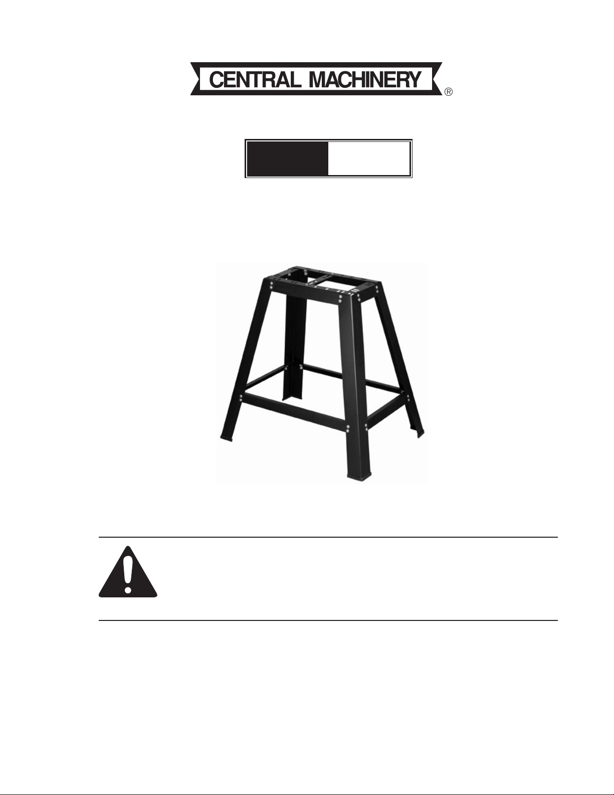
29” HEAVY DUTY TOOL STAND
Model
95128
ASSEMBLY AND OPERATING INSTRUCTIONS
Visit our website at: http://www.harborfreight.com
Read this material before using this product.
Failure to do so can result in serious injury.
SAVE THIS MANUAL.
Copyright© 2006 by Harbor Freight Tools®. All rights reserved. No portion of this manual or any artwork
contained herein may be reproduced in any shape or form without the express written consent of Harbor
Freight Tools. Diagrams within this manual may not be drawn proportionally. Due to continuing improve-
ments, actual product may differ slightly from the product described herein. Tools required for assembly
and service may not be included.
For technical questions or replacement parts, please call 1-800-444-3353.
Revised Manual 09l
Page 2

SPECIFICATIONS
ITEM DESCRIPTION
Construction Heavy Duty Formed & Stamped Alloy Sheet Steel; Black Pow-
der coated Finish & Zinc Plated Fasteners
Overall Dimensions 29-1/4”H x 30-1/2”L x 21-1/2”W
Stand Top Dimensions 18”L x 9-3-4”W (W/Adjustable Slots to Extend Width)
Max Load Capacity 300 Lbs.
Net Weight 14 Lbs.
SAVE THIS MANUAL
You will need the manual for the safety warnings and precautions, assembly
instructions, operating and maintenance procedures, parts list and diagram. Keep
your invoice with this manual. Write the invoice number on the inside of the front
cover. Keep the manual and invoice in a safe and dry place for future reference.
SAFETY WARNINGS AND PRECAUTIONS
Keep work area clean. 1. Cluttered areas invite injuries.
Observe work area conditions.2. Keep work area well lit.
Supervise children around this product.3. Do not allow children in the work area.
Check for damaged parts. 4. Before using any product, any part that appears dam-
aged should be carefully checked to determine that it will perform its intended function.
Check for any broken or damaged parts and any other conditions that may affect its
operation. Replace or repair damaged or worn parts immediately.
Use safety equipment. Wear ANSI-approved safety impact eye goggles when 5.
assembling this product or when using machinery with this product.
Always check hardware and assembled parts after assembling.6. All connections
should be tight and hardware tightened.
Do not overreach. 7. Keep proper footing and balance at all times when assembling
or using this product.
Stay Alert. 8. Watch what you are doing at all times. Use common sense.
When using this product, remember do not expose power tools to rain or wet 9.
conditions. Water entering a power tool will increase the risk of electric shock.
When operating a power tool outside, use an outdoor extension cord marked 10.
“W-A” or “W”. These extension cords are rated for outdoor use, and reduce the risk
of electric shock.
SKU 95128 For technical questions, please call 1-800-444-3353. Page 2
Page 3

11. Do not modify this tool to perform a task for which it was not designed. The
correct equipment will do the job better and safer at the rate for which it is designed.
Do not use small equipment, tools, or attachments to do the work of larger industrial
equipment, tools, or attachments. Do not use this product for a purpose for which it
was not intended.
12. Use goggles or breathing protection (not included) for mouth and nose during all
jobs that cause dust, chips, fumes or sparks.
13. Protect your hearing when doing work causing a lot of noise. Use ear plugs (not
included) if necessary.
14. Use HEAVY DUTY work gloves (not included) when working with tools and
equipment
15. Never allow inexperienced personnel to work with your equipment and tools without instructions and/or supervision.
16. Do not stand on top of the Heavy Duty Tool Stand.
17. Do not exceed the Tool Stand’s maximum weight capacity. (300 lbs.)
18. Do not let children stand on or play with the Heavy Duty Tool Stand.
19. Always use the Tool Stand on a flat, level surface that is able to withstand the
weight of the Tool Stand and the weight of the objects on the Tool Stand.
20. SAVE THESE INSTRUCTIONS.
WARNING: The warnings, cautions, and instructions discussed in this instruction manual can-
not cover all possible conditions and situations that may occur. It must be understood by the
operator that common sense and caution are factors which cannot be built into this product,
but must be supplied by the operator.
WARNING: Some dust created by power sanding, sawing, grinding, drilling, and other construction activities, contains chemicals known [to the State of California] to cause cancer,
birth defects or other reproductive harm. Some examples of these chemicals are:
Lead from lead-based paints
Crystalline silica from bricks and cement or other masonry products
Arsenic and chromium from chemically treated lumber
Your risk from these exposures varies, depending on how often you do this type of work.
To reduce your exposure to these chemicals: work in a well ventilated area, and work with
approved safety equipment, such as those dust masks that are specially designed to filter
out microscopic particles. (California Health & Safety Code § 25249.5, et seq.)
SKU 95128 For technical questions, please call 1-800-444-3353. Page 3
Page 4

UNPACKING
When unpacking this product check to make sure that all parts are included as shown in the
parts list. If any parts are missing or broken, please call Harbor Freight Tools at the number
below.
HARDWARE SPECIFICATION
Hardware to mount power tools to the Heavy Duty Tool Stand are not supplied. The recommended minimum size of mounting hardware is listed below. As a guide, actual sizes may
depend on tool base thickness.
Scroll Saw Miter Saw
Band Saw Joiner-Planer
Sander
Hex Head Bolts
Flat Washers
Hex Nuts
Depending on the tool you are mounting, the drawings on page 5 through 9 show assembly
according to the Top Braces for that particular tool. Note: The tool description is at the top of
each drawing. This will identify the tool to be mounted for that configuration.
1/4-20 x 1-/2 (4) 5/16-1/8 x 2-1/2
1/4 I.D. 3/4 O.D, 5/16 I.D. 7/8 O.D.
1/4-20 5/16-18
Drill Presses
UNIVERSAL BENCH POWER TOOLS
Fits the Following 29” Heavy Duty Tool Stand
8” Drill Press 4-1/8” Jointer Planer
9” Drill Press 13” Scroll Saw
10” Drill Press 15” Scroll Saw
10” Band Saw 16” Scroll Saw
12” Band Saw 10” Miter Saw
4” Belt & 6” Disc Sander (not for all models)
In the event your machine does not fit, simply put plywood or
particle board on the surface of the Top Braces (8, 9, 10 & 11).
SKU 95128 For technical questions, please call 1-800-444-3353. Page 4
Page 5

TOOL STAND ASSEMBLY
STEP 1
Install one Rubber Sleeve (1) onto each Leg (2). 1. See Figure 1.
Assemble front and rear sections, as shown in2. Figure 1 below. Insert the Carriage Bolts
(4) through the Legs (2), through the Braces and then into the retractable slots. Fasten
each piece with a Washer (5) and Hex Nut (6). Tighten the Nut.
3. Assemble the two Top Sides (8) to the Top Front & Rear Braces (9 & 11) See Figure 1
below.
STEP 2
1. Assemble this step according to the configuration of the tool you are mounting. See
Figure 1.
2. Once you have everything assembled, be sure to tighten all hardware securely.
CONFIGURATION FOR 13” sCROll sAw • 16” sCROll sAw • 12” bANd sAw
11
2
9
8
5 & 6
10
5 & 6
4
11
8
9
10
8
13” SCROLL SAW-Top Cross Brace (10) in holes
marked W & Z (2 holes)
4
16” SCROLL SAW-One Top Side (8) & Top Front &
Rear Braces (9 & 11) in holes marked D, I, & T
(3 holes)
1
7
3
12” BAND SAW-Top Front & Rear Braces (9 & 11)
in holes marked J, H, R, & V (4 holes)
Figure 1
STEP 3
1. In some cases the Top Cross Brace (10) will change positions depending on the
tool you are mounting. Assemble according to the configuration of the drawing pertaining the tool you are using. See Figure 1.
SKU 95128 For technical questions, please call 1-800-444-3353. Page 5
Page 6

CONFIGURATION FOR 4” belT & 6” dIsC sANdeR • 15” sCROll sAw • 10” MITeR sAw
2
9
1
8
5 & 6
7
2
10
11
4
5 & 6
3
11
8
10
9
8
#8D46 SANDER-Two Top Side Braces (8) in holes
marked A, D, N & Q (4 holes)
4
#8D46R SANDER-One Top Side (8), Top Cross
Brace (10) in holes marked N, O, W & Z (4 holes)
15” SCROLL SAW-One Top Side (8) and Top
Cross Braces (10) in holes marked O & X (2 holes)
10” MITER SAW-Top Front & Rear Braces (9 &
11) in holes marked F, L, S, & V (4 holes)
Figure 2
STEP 3
1. In some cases the Top Cross Brace (10) will change positions depending on the
tool you are mounting. Assemble according to the configuration of the drawing pertaining the tool you are using. See Figure 2.
SKU 95128 For technical questions, please call 1-800-444-3353. Page 6
Page 7

CONFIGURATION FOR 10” BAND SAW
8
9
2
5 & 6
1
STEP 3
7
2
10
11
4
5 & 6
3
11
8
8
9
10” BAND SAW-One Top Side (8) and one Top
4
10
Cross Brace (10) in holes marked D, P, W & Y
(4 holes)
Figure 3
1. In some cases the Top Cross Brace (10) will change positions depending on the
tool you are mounting. Assemble according to the configuration of the drawing pertaining the tool you are using. See Figure 3.
SKU 95128 For technical questions, please call 1-800-444-3353. Page 7
Page 8

CONFIGURATION FOR 8” dRIll PRess • 9” dRIll PRess
• 10” dRIll PRess
9
2
1
STEP 3
8
5 & 6
7
2
10
11
4
5 & 6
3
11
8
8
10
9
4
DRILL PRESS-Top Cross Brace (10) in holes W & Z
(2 holes).
Figure 4
3. In some cases the Top Cross Brace (10) will change positions depending on the
tool you are mounting. Assemble according to the configuration of the drawing pertaining the tool you are using. See Figure 4.
SKU 95128 For technical questions, please call 1-800-444-3353. Page 8
Page 9

CONFIGURATION FOR 4-1/8” JOINTER-PLANER
11
2
9
1
8
5 & 6
7
7
2
11
8
4
5 & 6
4-1/8” JOINTER-PLANER-One Top Side
Brace (8) in holes marked A, E, M & Q
(4 holes)
Top Cross Brace (10) not used
4
Figure 5
MAINTENANCE
8
9
1. Wipe down Tool Stand after each use with a dry cloth and store in a secure place.
2. If any oil or grease is on the Tool Stand, clean with a cleaning solvent and wipe area
dry.
SKU 95128 For technical questions, please call 1-800-444-3353. Page 9
Page 10

PARTS IDENTIFICATION
Part # Description Qty.
1 Rubber Sleeve “L” 4
2 Leg 4
3 Bottom Side Brace 2
4 Carriage bolt M6 x 1.0-12 34
5 Flat Washer 5/16 34
6 Hex Nut 6 x 1.0 34
7 Bottom Front & Rear Brace 2
8 Top Side Brace 1
9 Top Front Brace 1
10 Top Cross Brace 1
11 Top Rear Brace 1
4,5,6
10
11
8
9
8
2
7
3
2
3
7
2
1
2
PLEASE READ THE FOLLOWING CAREFULLY
THE MANUFACTURER AND/OR DISTRIBUTOR HAS PROVIDED THE PARTS DIAGRAM IN THIS MANUAL AS A
REFERENCE TOOL ONLY. NEITHER THE MANUFACTURER NOR DISTRIBUTOR MAKES ANY REPRESENTATION OR WARRANTY OF ANY KIND TO THE BUYER THAT HE OR SHE IS QUALIFIED TO MAKE ANY REPAIRS
TO THE PRODUCT OR THAT HE OR SHE IS QUALIFIED TO REPLACE ANY PARTS OF THE PRODUCT. IN
FACT, THE MANUFACTURER AND/OR DISTRIBUTOR EXPRESSLY STATES THAT ALL REPAIRS AND PARTS
REPLACEMENTS SHOULD BE UNDERTAKEN BY CERTIFIED AND LICENSED TECHNICIANS AND NOT BY
THE BUYER. THE BUYER ASSUMES ALL RISK AND LIABILITY ARISING OUT OF HIS OR HER REPAIRS TO
THE ORIGINAL PRODUCT OR REPLACEMENT PARTS THERETO, OR ARISING OUT OF HIS OR HER INSTALLATION OF REPLACEMENT PARTS THERETO.
SKU 95128 For technical questions, please call 1-800-444-3353. Page 10
Page 11

LIMITED 90 DAY WARRANTY
Harbor Freight Tools Co. makes every effort to assure that its products meet high
quality and durability standards, and warrants to the original purchaser that this product
is free from defects in materials and workmanship for the period of 90 days from the date
of purchase. This warranty does not apply to damage due directly or indirectly, to misuse,
abuse, negligence or accidents, repairs or alterations outside our facilities, criminal activity, improper installation, normal wear and tear, or to lack of maintenance. We shall in
no event be liable for death, injuries to persons or property, or for incidental, contingent,
special or consequential damages arising from the use of our product. Some states do
not allow the exclusion or limitation of incidental or consequential damages, so the above
limitation of exclusion may not apply to you. THIS WARRANTY IS EXPRESSLY IN LIEU
OF ALL OTHER WARRANTIES, EXPRESS OR IMPLIED, INCLUDING THE WARRANTIES OF MERCHANTABILITY AND FITNESS.
To take advantage of this warranty, the product or part must be returned to us
with transportation charges prepaid. Proof of purchase date and an explanation of the
complaint must accompany the merchandise. If our inspection verifies the defect, we
will either repair or replace the product at our election or we may elect to refund the
purchase price if we cannot readily and quickly provide you with a replacement. We will
return repaired products at our expense, but if we determine there is no defect, or that
the defect resulted from causes not within the scope of our warranty, then you must bear
the cost of returning the product.
This warranty gives you specific legal rights and you may also have other rights
which vary from state to state.
3491 Mission Oaks Blvd. • PO Box 6009 • Camarillo, CA 93011 • (800) 444-3353
SKU 95128 For technical questions, please call 1-800-444-3353. Page 11
 Loading...