

Page 1
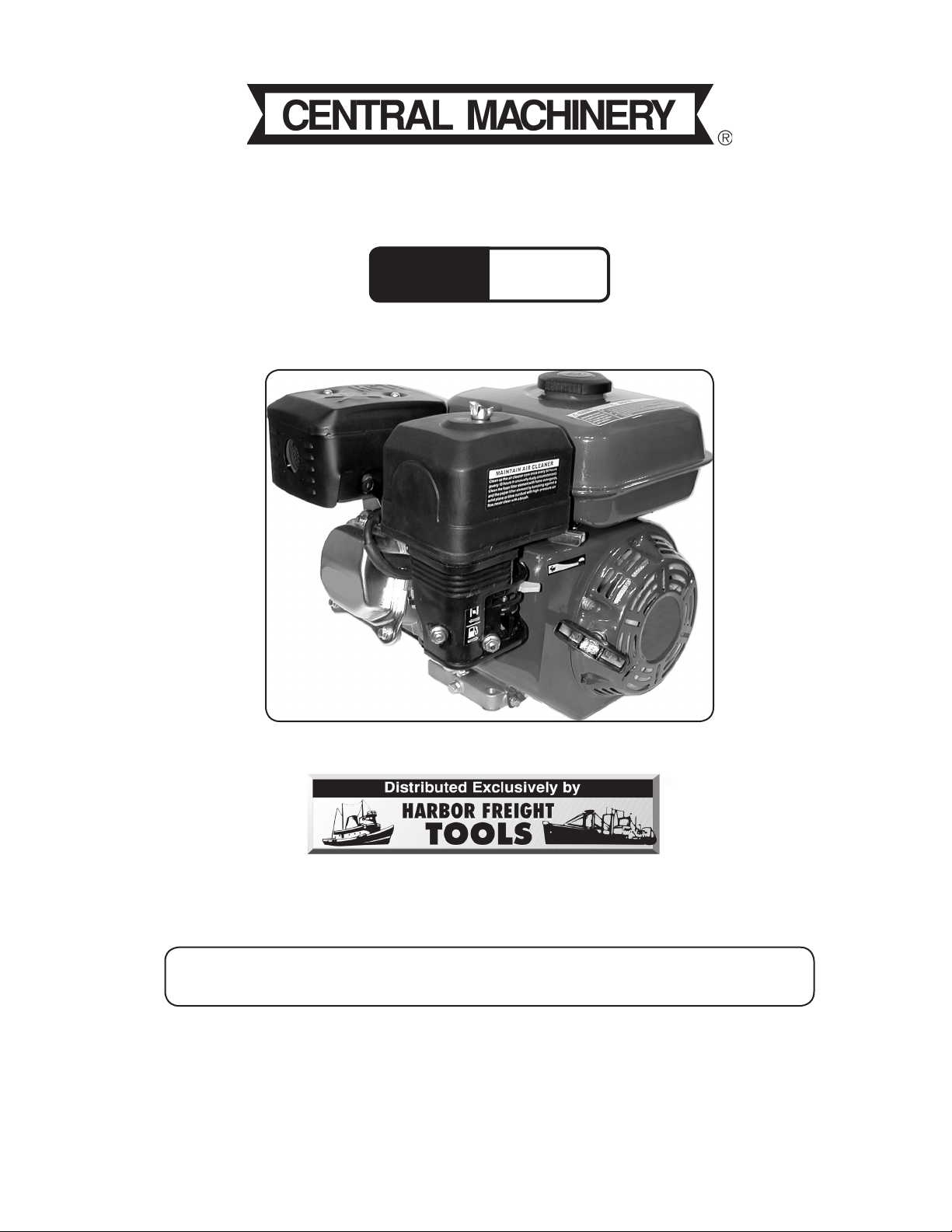
GAS ENGINE - 6.5 HP
Model
94187
®
ASSEMBLY AND OPERATION INSTRUCTIONS
Due to continuing improvements, actual product may differ slightly from the product described herein.
3491 Mission Oaks Blvd., Camarillo, CA 93011
Visit our website at: http://www.harborfreight.com
TO PREVENT SERIOUS INJURY, READ AND UNDERSTAND
ALL WARNINGS AND INSTRUCTIONS BEFORE USE.
Copyright© 2006, 2007 by Harbor Freight Tools®. All rights reserved. No portion of this
manual or any artwork contained herein may be reproduced in any shape or form without
the express written consent of Harbor Freight Tools.
For technical questions or replacement parts, please call 1-800-444-3353.
Manual revised 02/07.
Page 2

Contents
SPECIFICATIONS ......................................................................................... 3
Save This Manual ............................................................................................... 3
SAFETY WARNINGS AND PRECAUTIONS ................................................ 3
UNPACKING ................................................................................................. 5
MOUNTING ................................................................................................... 6
OPERATION .................................................................................................6
Controls and Indicators ......................................................................................6
Pre-Operation Checks ........................................................................................ 7
TROUBLESHOOTING .................................................................................. 8
General/Basic Troubleshooting .......................................................................... 8
Engine Difficult to Start ...................................................................................... 9
Low Engine Power .............................................................................................10
Engine not Running Smoothly ............................................................................ 10
Engine Excessively Hot ...................................................................................... 11
Abnormal Engine Noise .....................................................................................12
MAINTENANCE ............................................................................................ 13
Scheduled Maintenance ..................................................................................... 13
Cleaning Air Filter ............................................................................................... 13
Cleaning and Replacing Spark Plug ..................................................................13
Changing Oil ......................................................................................................14
Cleaning the Deposit Cup ..................................................................................14
Torque Value for Major Engine Bolts .................................................................. 15
Transporting the Engine ..................................................................................... 15
Storing the Engine ............................................................................................. 15
PARTS LISTS AND ASSEMBLY DIAGRAMS .............................................. 16
Crankcase .......................................................................................................... 16
Crankcase Cover ................................................................................................17
Cylinder Head and Cover ...................................................................................18
Parts List ............................................................................................................18
Crankshaft, Piston, and Connecting Rod ........................................................... 19
Camshaft and Rocker Valve ............................................................................... 20
Carburetor .......................................................................................................... 21
Fuel Tank ............................................................................................................22
Air Cleaner .........................................................................................................23
Muffler ................................................................................................................24
Recoil Starter .....................................................................................................25
Regulator Control ............................................................................................... 26
Flywheel ............................................................................................................. 27
Ignition Coil ........................................................................................................28
Wiring Diagram ..................................................................................................29
WARRANTY ..................................................................................................29
Emission Control System Warranty .................................................................... 30
SKU 94187 For technical questions, please call 1-800-444-3353
Page 2
Page 3
SPECIFICATIONS
Power Output 6.5 HP Gas Engine, EPA and CARB approved
Displacement / Stroke 196 cc; 4-stroke
Ignition Type Electronic ignition (T.C.I.)
Cooling System Forced air cooling
Idling Carburetor Adjust 1700 +/- 150 RPM
Valve clearance Cold engine – Intake: 0.15 +/- 0.02mm;
Exhaust: 0.20 +/- 0.02 mm
Distributor Timing Intake valve opening: BTDC10’;
Intake valve closing: ABDC20’
Bore and Stroke 68 x 54 mm
Spark Plug Type BP6ES, BPR6ES (NGK), or NHSPLD F6RTCU; 0.7~0.8 mm clearance
Gasoline Type Unleaded
Gasoline Tank Capacity 0.95 gallon (3.6 liters)
Drive Shaft Type Horizontal, ¾” straight, (3/16”) keyed shaft with ball bearings. Direction:
counterclockwise (facing shaft); Length: 2-1/4”; Central thread: 5/16”-24
Start Type Recoil
Speed 3600 RPM
Oil Capacity and Type 0.528 quart (0.5 liters); SAE 10W30 (in freezing weather use 5W30)
Engine Mounting Square pattern, 4 holes; 8.0-1.25 mm threads
Weight 33.8 lbs.
Overall Dimensions 12.3 (L) x 15.6 (W) x 13.2 (H) inches
Recommended Applications To drive: pump, sprayer, tiller, chipper, shredder, log splitter
Features Low oil shutdown, automatic
Longer engine life with bearing supported shaft
Meets 2005 EPA Phase II Cal. Emission Regs.
Fuel shutoff valve
The Emission Control System for this generator’s engine is warranted for standards set
by the U.S. Environmental Protection Agency and by the California Air Resources Board (also
known as CARB). For warranty information, refer to the back two pages of this manual.
Save This Manual
You will need the manual for the safety warnings and precautions, assembly instructions, operating and maintenance procedures, parts list and diagram. Keep your invoice with
this manual. Write the invoice number on the inside of the front cover. Keep the manual and
invoice in a safe and dry place for future reference.
SAFETY WARNINGS AND PRECAUTIONS
WARNING: When using this Gas Engine, basic safety precautions should always be followed to reduce
the risk of personal injury and damage to equipment.
Read all instructions before using this tool!
1.
2.
Keep work area clean. Cluttered areas invite injuries.
Observe work area conditions. Do not use machines or power tools in damp or wet
locations. Don’t expose to rain. Keep work area well lighted. Do not use electrically
powered tools in the presence of flammable gases or liquids.
SKU 94187 For technical questions, please call 1-800-444-3353
Page 3
Page 4

3.
Keep children away. Children must never be allowed in the work area. Do not let
them handle machines, tools, or extension cords.
4.
5.
6.
7.
8.
9.
10.
Store idle equipment. When not in use, tools must be stored in a dry location to inhibit
rust. Always lock up tools and keep out of reach of children.
Dress properly. Do not wear loose clothing or jewelry as they can be caught in moving
parts. Wear restrictive hair covering to contain long hair.
Use the right tool for the job. Do not attempt to force a small tool or attachment to
do the work of a larger industrial tool. There are certain applications for which this tool
was designed. It will do the job better and more safely at the rate for which it was in-
tended. Do not modify this tool and do not use this tool for a purpose for which it was
not intended.
Use eye and ear protection. Always wear ANSI approved impact safety goggles and
ear plugs.
Do not overreach. Keep proper footing and balance at all times. Do not reach over
or across running machines.
Maintain tools with care. Keep tools sharp and clean for better and safer performance.
Follow instructions for lubricating and changing accessories.
Remove adjusting keys and wrenches. Check that keys and adjusting wrenches are
removed from the tool or machine work surface before starting.
11.
12.
13.
14.
15.
16.
Avoid unintentional starting. Be sure the power switch and gas valve are in the Off
position when not in use.
Stay alert. Watch what you are doing, use common sense. Do not operate any tool
when you are tired.
Check for damaged parts. Before using this Gas Engine, any part that appears dam-
aged should be carefully checked to determine that it will operate properly and perform
its intended function. Check for alignment and binding of moving parts; any broken parts
or mounting fixtures; and any other condition that may affect proper operation. Any part
that is damaged should be properly repaired or replaced by a qualified technician. Do
not use the Gas Engine if the switch does not turn On and Off properly.
Do not operate this Gas Engine if under the influence of alcohol or drugs. Read
warning labels if taking prescription medicine to determine if your judgment or reflexes
are impaired while taking drugs. If there is any doubt, do not operate the tool.
Maintenance. For your safety, service and maintenance should be performed regularly
by a qualified technician.
People with pacemakers should consult their physician(s) before use. Electromag-
netic fields in close proximity to heart pacemaker could cause pacemaker interference
or pacemaker failure.
Caution is necessary when near coil, spark plug cables, or distributor of running engine.
Engine should be off during distributor adjustment.
SKU 94187 For technical questions, please call 1-800-444-3353
Page 4
Page 5

17.
Fire Hazard! Do not fill gas tank when the engine is running. Do not operate if
gasoline has been spilled. Clean spilled gasoline before starting the engine. Do not
operate near a pilot light or open flame.
18.
19.
20.
21.
22.
23.
Operate the engine in well ventilated areas only. Carbon Monoxide is
produced during operation and is deadly in a closed environment. Early
signs of Carbon Monoxide poisoning resemble the flu, with headaches, dizziness, or nausea. If you have these signs, the engine may not be working
properly, or is being used indoors. Get fresh air immediately.
Avoid burns from the engine. Certain parts of the engine become very hot during
use. Do not touch the engine until it cools down after use.
Install this product on a proper surface. Locate on a flat, level, and solid surface that
is capable of supporting the weight of the engine and the machinery that it is turning.
Do not operate the engine with safety guards removed. While the engine is running, do not attempt to reach around the safety guards for maintenance or any other
reason.
If the engine is installed indoors, exhaust fumes must be piped out of the building using leak-free, heat-resistant piping. Pipes and silencer should not use any
flammable materials, nor should they be installed near the same. Engine exhaust fumes
should be within legal limits.
Engine fuel and fumes are flammable, and potentially explosive. Do not smoke,
or allow sparks, flames or other sources of ignition around the engine, fuel tanks,
or batteries. Use proper fuel storage and handling procedures. Always have multiple
ABC class fire extinguishers nearby.
24.
25.
26.
Warning: The warnings, cautions, and instructions discussed in this instruction manual can-
Never store fuel or other flammable materials near the engine.
Keep hands, arms, long hair, loose clothing, and jewelry away from pulleys, belts,
and other moving parts. Be aware that when engine parts are moving fast they can-
not be seen clearly.
The engine can produce high noise levels. Prolonged exposure to noise levels above
85 dBA is hazardous to hearing. Always wear ear protection when operating or working
around the Gas Engine when it is running.
not cover all possible conditions and situations that may occur. It must be understood
by the operator that common sense and caution are factors which cannot be built into
this product, but must be supplied by the operator.
UNPACKING
When unpacking, check to make sure the following parts are included. If any parts are
missing or broken, please call Harbor Freight Tools at the number on the cover of this manual
as soon as possible.
SKU 94187 For technical questions, please call 1-800-444-3353
Page 5
Page 6
MOUNTING
1.
2.
Mount the Engine using its four mounting holes at the base (hardware not supplied).
Select a flat, smooth location able to withstand the weight, vibration, and the load device
connected to the Engine. If installed indoors, proper exhaust ventilation tubing must be
installed. If installed outdoors, a weatherproof housing is recommended.
Install the Engine load.
The Engine load must be perfectly aligned with the Engine drive shaft to prevent undue
wear on the shaft and bearings. A qualified technician should do this.
OPERATION
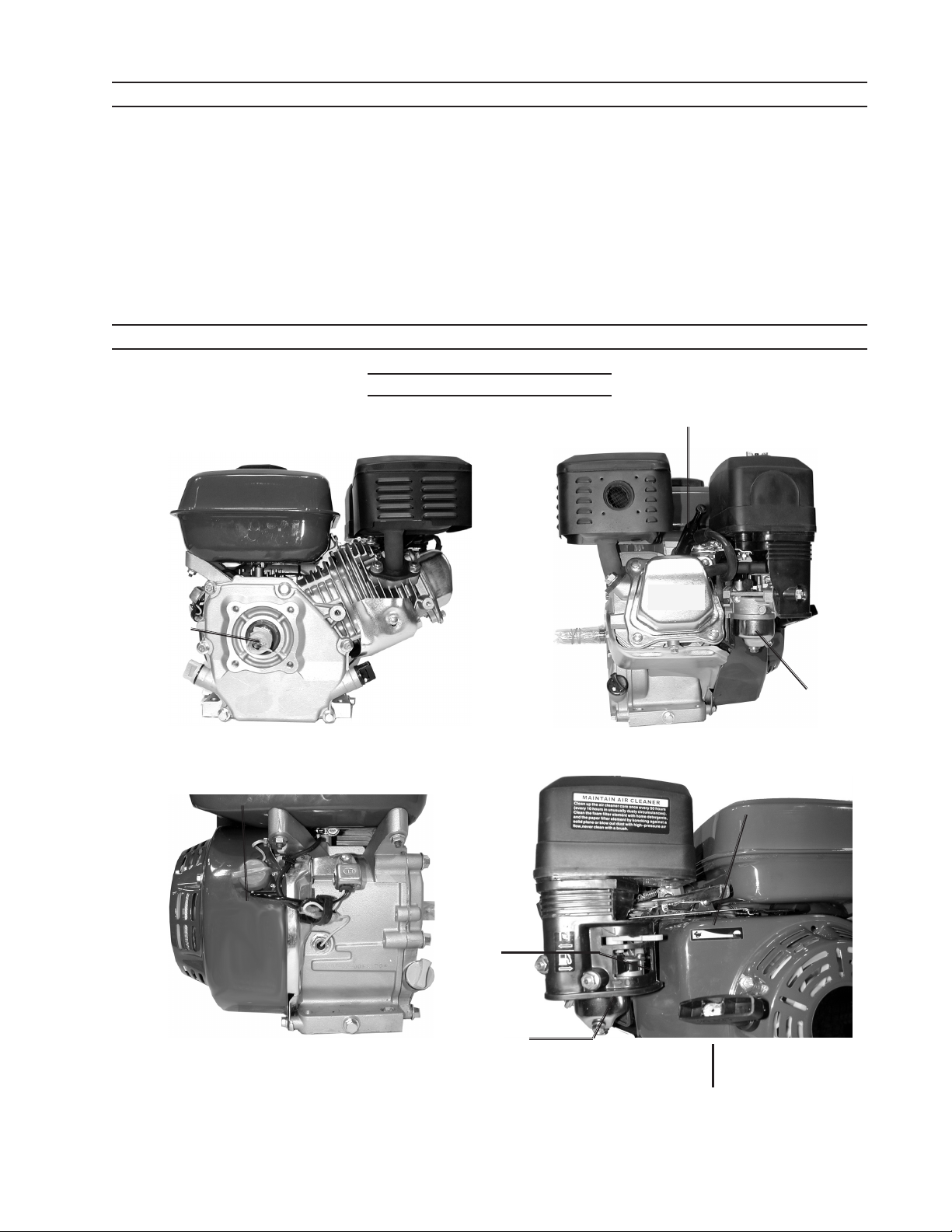
Controls and Indicators
Spark Plug
Fuel Tank Cap
Muffler
Muffler
Air Filter
Drive Shaft
On / Off Switch
Oil PlugDip Stick
Drain Plug
Oil Plug
Deposit Cup
Drain Plug
Throttle
Choke
Gas Valve
Starter Pull Cord
SKU 94187 For technical questions, please call 1-800-444-3353
Page 6
Page 7
Pre-Operation Checks
Caution: Failure to add oil to the Engine before use will damage the Engine and void the fac-
tory warranty. Engine oil is the key factor in engine performance. Do not use Engine oil
with additives; Do not use two-stroke gasoline-oil. Using these will shorten Engine life.
See Specifications on page 2 for recommended oil type.
1.
2.
3.
Check that all installation mounting nuts and bolts are tight.
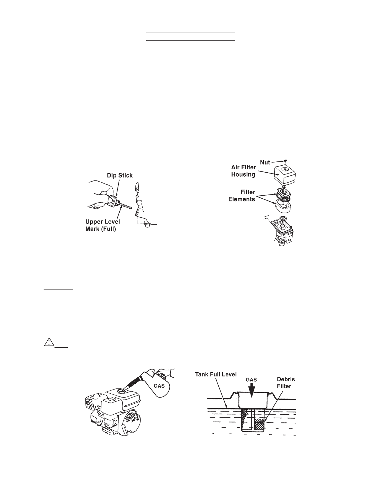
Check oil level (See illustration below, left.) If needed, add oil as specified on page 2.
Unscrew the oil Dip Stick and wipe clean. Insert the Dip Stick back into the hole without
screwing it in. Remove it again and check the oil level. Full is indicated by oil on the
Upper Level mark. Use a siphon to avoid spilling the oil. Carefully screw the plastic Dip
Stick back into the metal Engine crankcase to avoid stripping the plastic threads on the
Dip Stick.
Check Air Filter. (See illustration above, right.) Unscrew Air Filter Housing Nut and
remove the Air Filter Housing and Filter Elements. If dirty or dusty, clean (refer to the
Maintenance Section).
Caution: Never run the Engine without the Air Filter assembly. Damage will occur to En-
gine.
4.
SKU 94187 For technical questions, please call 1-800-444-3353
Remove the debris filter, clean and replace it before filling. Fill the Gas Tank (outdoors)
with up to 0.95 of a gallon of unleaded gasoline containing at least 86 octane. Do not
top-off tank. Replace Gas Cap. Clean up any spilled gas with a dry cloth.
Fire Hazard! Do not fill Gas Tank when the Engine is running, or near a pilot light or open
flame; Do not smoke. Do not operate if gasoline has been spilled. Clean spilled gasoline
before starting the engine.
Page 7
Page 8
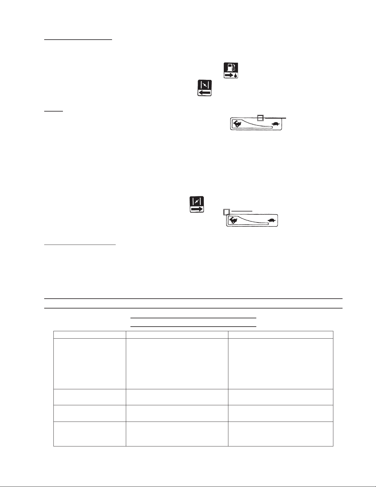
Starting the Engine
During this procedure, it may be helpful to refer to the photos of the Engine Controls on
page 5.
1.
2.
Push the Gas Valve to the open (right) position.
Close the Choke by pulling it to the left.
Note: If the Engine is already hot, it is not necessary to close the Choke.
3.
Push the Throttle Lever to the slow (right) position , then move it back
slightly.
4.
5.
Turn the On/Off Switch to the On position.
Gently pull the Starter Pull Cord until it engages. Then pull it hard and all the way out.
Slowly guide the Pull Cord back into the starter.
The Engine should start. Try again if it does not start. Refer to the Troubleshooting section if problems persist. Let the engine run for five minutes to warm up.
6.
7.
Push in the Choke Lever to the right/
Push the Throttle Lever to the fast position (left).
Throttle Setting
Stopping the Engine
Throttle Setting
1.
2.
3.
Push the Throttle Lever to the slow (right) position.
Turn the On/Off Switch to the Off position.
Push the Gas Valve to the closed (left) position.
TROUBLESHOOTING
General/Basic Troubleshooting
Symptom Probable Cause Possible Remedy
Engine will not start. 1. On/Off Switch in Off position.
2. Gas Valve in closed position.
3. Choke set to open position.
4. Gas Tank empty.
5. Spark plug dirty.
6. Technical problem.
Engine runs rough,
pinging noises.
Engine stops by itself,
but has gas.
Engine does not reach
full speed.
1. Gasoline wrong type.
2. Gasoline has water.
1. Low oil level auto shut off.
2. Technical problem.
1. Choke closed.
2. Air filters clogged.
3. Technical problem.
1. Turn to On position.
2. Push to open position.
3. Set to closed position.
4. Fill Gas Tank.
5. Remove spark plug and clean.
6. Service by qualified mechanic.
1. Replace with 89 octane gas.
2. Empty tank and replace gas.
1. Check oil level; Add if needed.
2. Service by qualified mechanic.
1. Open Choke.
2. Clean air filter elements.
3. Service by qualified mechanic.
SKU 94187 For technical questions, please call 1-800-444-3353
Page 8
Page 9

Symptom Probable Cause Possible Remedy
Engine difficult to start
Engine Difficult to Start
Fuel supply blocked:
– Cylinder compression
OK
– Spark OK
Engine difficult to start
– Cylinder compression
OK
– Spark OK
– Gas supply OK
Engine difficult to start
– Cylinder Compression
OK
– Gas supply OK
– Ignition coil spark OK
Engine difficult to start
– Gas supply OK
1. Air vent in Gas Cap clogged.
2. Gas Valve plugged up
3. Main jet clog or misadjusted
4. Needle valve improperly
closed or start hole is clogged
5. Floater in fuel tank is
damaged or sticking
Fuel system problem:
1. Gas dirty, has water, or is old
2. Engine cylinder flooded
3. Gas wrong type
1. Spark plug has carbon
buildup or dirt on and around
electrodes
2. Electrodes are burned
3. Improper spark gap
1. Piston ring worn
2. Piston ring is sticking
1. Clean Gas Cap air vent
2. Unclog Gas Valve
3. Clean and/or readjust
4. Take apart needle valve and
repair, clean, and blow out
5. Repair floater
1. Drain gas and replace
2. Drain extra gas, dry spark
plug electrodes
3. Drain gas and replace
1. Remove spark plug and
clean
2. Replace spark plug
3. Adjust spark plug electrodes
1. Replace piston rings
2. Clean out carbon fouling
– Ignition system OK
3. Piston ring broken
4. Spark plug loose or without a
gasket
5. Air leakage between cylinder
block and cylinder
6. Air leakage in valve
3. Replace piston ring
4. Tighten with a gasket
5. Check cylinder gasket and
bolts
6. Check valve clearance and
thickness, repair if required
SKU 94187 For technical questions, please call 1-800-444-3353
Page 9
Page 10

Symptom Probable Cause Possible Remedy
When pressing Throttle
for higher speed, engine
responds slowly; speed is
decreased; or engine stops.
Low Engine Power
Incorrect Ignition timing. Re-adjust ignition advance angle.
Fuel supply problem:
1. Fuel line is clogged or has air
1. Clean line. Bleed line of air.
2. Main jet not adjusted properly
3. Carburetor needle valve hole
and main jet clogged
4. Gas valve clogged
5. Carbon buildup in combustion
chamber.
6. Air filter is clogged.
7. Intake pipe leaking.
Low compression:
1. Piston, piston ring, or cylinder
worn.
2. Air leakage from surface
where cylinder block contacts
cylinder head.
3. Valve clearance incorrect.
4. Valve tightness poor.
Engine not Running Smoothly
Symptom Probable Cause Possible Remedy
Engine pinging. 1. Piston, ring, or cylinder worn.
2. Readjust jet.
3. Clean needle valve hole and
main jet
4. Clean or replace gas valve.
5. Clean combustion chamber.
6. Clean filter elements.
7. Repair or replace.
1. Replace damaged part.
2. Replace cylinder gaskets.
3. Adjust valve.
4. Repair or replace valve.
1. Replace worn part.
2. Piston pin and pin hole are
worn excessively.
3. Tie rod small head is worn.
4. Main crankshaft roller bearing
worn.
Abnormal combustion. 1. Engine too hot.
2. Carbon fouling in combustion
chamber.
3. Wrong gasoline type.
Spark plug not firing
correctly
1. Water in carburetor float
chamber.
2. Spark plug electrode gap
wrong.
3. Incorrect ignition timing.
4. Ignition coil malfunction.
2. Replace piston and/or pin.
3. Replace tie rod.
4. Replace roller bearing.
1. Troubleshoot overheating
(see page 11).
2. Clean chamber.
3. Drain gas from system and
replace with correct type.
1. Clean Carburetor.
2. Adjust spark plug gap.
3. Re-adjust.
4. Repair or replace coil.
SKU 94187 For technical questions, please call 1-800-444-3353
Page 10
Page 11

Symptom Probable Cause Possible Remedy
Engine stops suddenly. 1. Gas tank empty.
1. Fill gas tank.
Symptom Probable Cause Possible Remedy
Engine runs excessively
hot.
2. Carburetor clogged
3. Floater is leaking.
4. Needle valve sticks.
5. Spark plug dirty or damaged.
6. Spark plug connector wire
damaged or disconnected.
7. Low oil auto-shutdown.
8. Ignition coil damaged.
9. Cylinder or valve damaged.
Engine Excessively Hot
1. Ignition timing off.
2. Engine oil low.
3. Exhaust pipe or muffler
clogged.
2. Clean carburetor and check
fuel line.
3. Repair or replace.
4. Disassemble floater chamber
and clean.
5. Replace spark plug.
6. Check and repair spark plug
wire.
7. Fill with oil.
8. Repair or replace.
9. Disassemble, check, and
repair.
1. Adjust ignition advance
angle.
2. Fill with oil.
3. Clean out exhaust pipe and
muffler.
4. Flow guard is leaking.
5. Cooling fan loose, damaged,
or clogged.
6. Cylinder, piston, or piston
ring is worn resulting in air
flow between cylinder and
crankcase.
7. Engine speed maximum set
too high.
8. Crankshaft main bearing
burnt.
4. Repair leakage.
5. Clean, repair, or replace fan.
6. Replace damaged parts.
7. Re-adjust engine speed
governor.
8. Replace main bearing.
SKU 94187 For technical questions, please call 1-800-444-3353
Page 11
Page 12

Symptom Probable Cause Possible Remedy
Noise of piston banging, or
other metal-on-metal
Abnormal Engine Noise
1. Piston, piston ring, or cylinder
worn.
1. Replace worn parts.
2. Tie rod, piston pin and hole
worn.
3. Crankshaft main bearing
worn.
4. Piston ring broken.
5. Carbon deposits in
combustion chamber.
6. Spark plug gap too small.
7. Using wrong gasoline.
8. Engine running too hot.
9. Incorrect valve clearance.
10. Flywheel not tightly
connected to crankshaft.
2. Replace worn parts.
3. Replace main bearing.
4. Replace piston ring.
5. Clean combustion chamber.
6. Adjust electrode clearance.
7. Empty gas tank and refill with
proper gasoline.
8. See Troubleshooting
Excessively Hot Engine.
9. Readjust valve clearance.
10. Retighten flywheel.
SKU 94187 For technical questions, please call 1-800-444-3353
Page 12
Page 13
MAINTENANCE
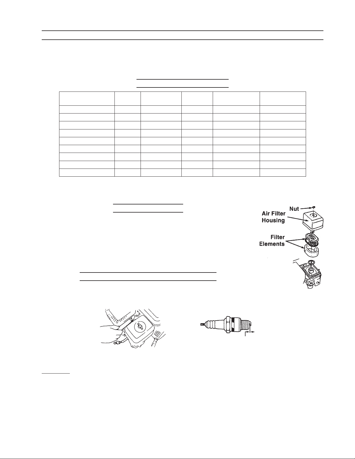
Before performing maintenance procedures, it may be helpful to locate the items to be
serviced in the photos on page 5. Many Engine maintenance, adjustments, and repairs must
be completed by a qualified, small engine mechanic.
Scheduled Maintenance
Frequency
Item
Engine oil Check Replace Replace
Air Filter Check Clean Clean Replace
Spark Plug Clean & Adjust Replace
Spark Eliminator Clean
Idling Check & Adjust*
Valve Clearance Check & Adjust**
Fuel Tank & Filter Clean
Fuel Line Check
Deposit Cup Clean
* Proper Idle: 1700 ± 150 RPM ** Valve Clearance
Each
Use
First month
or 20 hours
Each 50
hours
(cold engine)
Every 6 months
or 100 hrs.
Intake:
Exhaust:
Cleaning Air Filter
Using compressed air, blow the dust from both elements and
the Filter Base on the Engine. If the Filter Elements cannot be cleaned,
wash the foam element with mild soap and water, and dry. Purchase
a new paper Filter Element if necessary. Reinstall Filter Elements, Air
Filter Housing, and Nut.
Each year or
300 hrs.
0.15 ± 0.02mm
0.20 ± 0.02mm
Cleaning and Replacing Spark Plug
1.
2.
Caution: Using other than the recommended Spark Plug replacement type can damage the
3.
SKU 94187 For technical questions, please call 1-800-444-3353
Remove the Spark Plug with a socket wrench (not supplied).
Wait for the Engine to cool to avoid burning hands.
.027” to .031”
Clean Spark Plug with a steel brush. If the insulator is damaged, replace Spark Plug.
Engine (see Specifications on page 2).
Measure the Spark Plug electrode gap with a feeler gauge (not supplied). It should be
between 0.7 to 0.8 mm. If adjustment is necessary, bend the side electrode carefully,
then re-measure. If Spark Plug Gasket is damaged, replace it.
Page 13
Page 14
4.
Replace Spark Plug by hand for the first few turns, then tighten with the socket wrench
completely. Securely tighten. A Spark Plug with a new Gasket requires 1/2 more turns
to tighten than the used Gasket which requires 1/8 to 1/4 turns to tighten.
Changing Oil
1.
2.
3.
4.
5.
6.
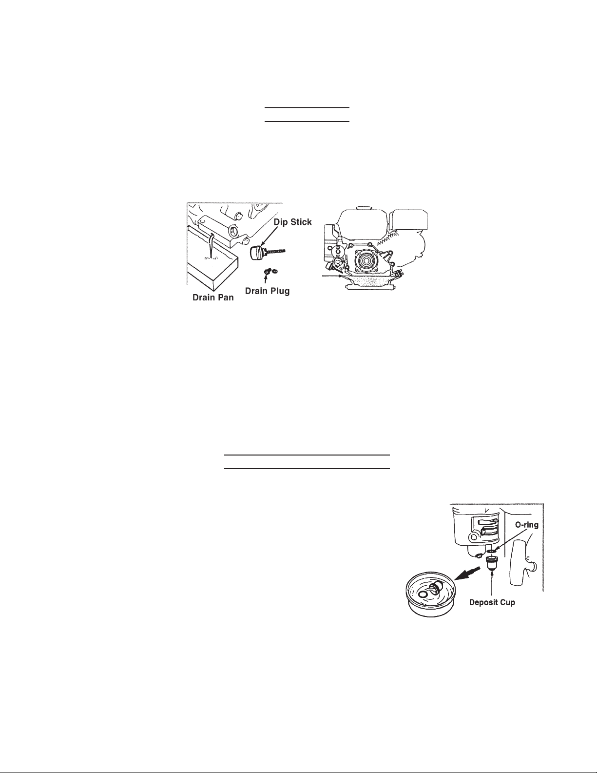
Run the Engine for five minutes to warm up the oil, then shut off the Engine.
Place a drain pan under the Drain Plug.
Remove the Dip Stick and unscrew the Drain Plug.
Allow all the oil to drain out into the pan. Pour the used oil into a container with a lid.
Deliver used oil to a recycling center. Do not dump oil into the earth or storm drain.
Dispose of oil properly.
Replace Drain Plug and securely tighten.
Add 1/2 quart of 10W30 motor oil through a funnel (not included) into the Dip Stick fill
hole. Fill until the oil reaches the Upper Level line of the fill hole.
7.
1.
2.
3.
4.
5.
Replace the Dip Stick, being careful not to strip its plastic threads.
Cleaning the Deposit Cup
Push the Gas Valve to the closed (left) position.
Using a wrench (not supplied), loosen and remove the Bolt
under the Deposit Cup. Place a pan below the Deposit
Cup to catch any remaining gasoline.
Remove the Deposit Cup and O-ring, and wash them in
cleaning solvent.
Reinstall the Deposit Cup.
Push the Gas Valve to the open (right) position and check
for gas leaks from the Deposit Cup. If leaks are found, reinstall the Deposit Cup and
tighten hardware.
SKU 94187 For technical questions, please call 1-800-444-3353
Page 14
Page 15
Torque Value for Major Engine Bolts
Item Torque Value (ft-lb)
Cylinder Head Bolts 18
Flywheel Bolt 52~59
Crankcase Cover Bolts 18
Connecting Rod 9
Transporting the Engine
1.
2.
3.
1.
2.
3.
Press the Gas Valve to the left (closed) position.
Wait until the engine is cool before lifting and moving.
Keep the Engine level while carrying with another person.
Storing the Engine
Replace the Engine oil with new oil before storing as described on page 13.
Remove the Spark Plug as described on page 12. Add a spoon of new Engine oil
through the Spark Plug mounting hole, into the cylinder. Rotate the driveshaft to distribute the oil evenly. Replace the Spark Plug. Wipe up any spilled oil.
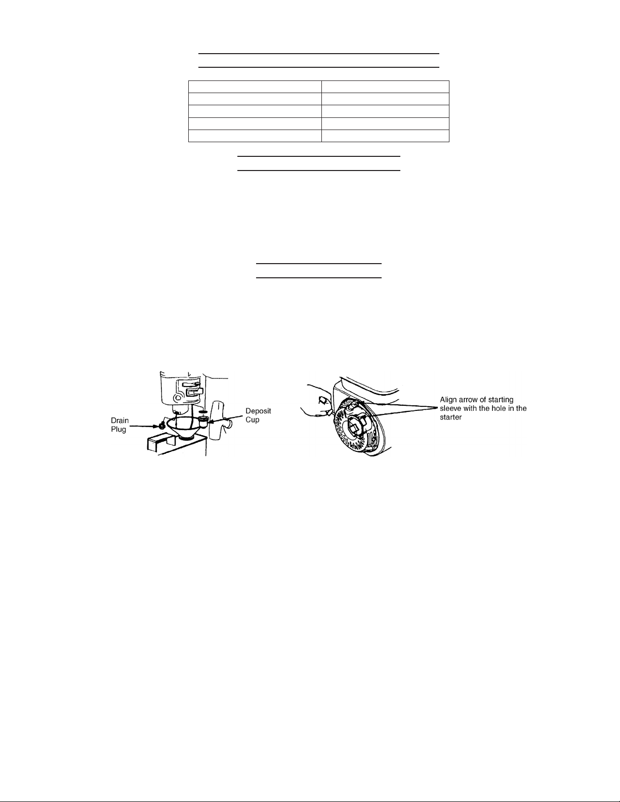
With a gas can (and funnel, neither included) underneath the Deposit Cup, unscrew
the Drain Plug of the Deposit Cup and drain all the gasoline from the Gas Tank. The
Gas Valve must be open. When drained, replace the Drain Plug. See illustration above,
left.
4.
Pull the Starter Pull Cord slowly, and when it engages keep pulling until the arrow on
the starting sleeve aligns with the hole of the starter. See illustration above, right. This
step ensures that the inlet and outlet valves are closed, preventing a buildup of moisture
and rust within the engine.
5.
Cover the Engine with a waterproof cover.
SKU 94187 For technical questions, please call 1-800-444-3353
Page 15
Page 16
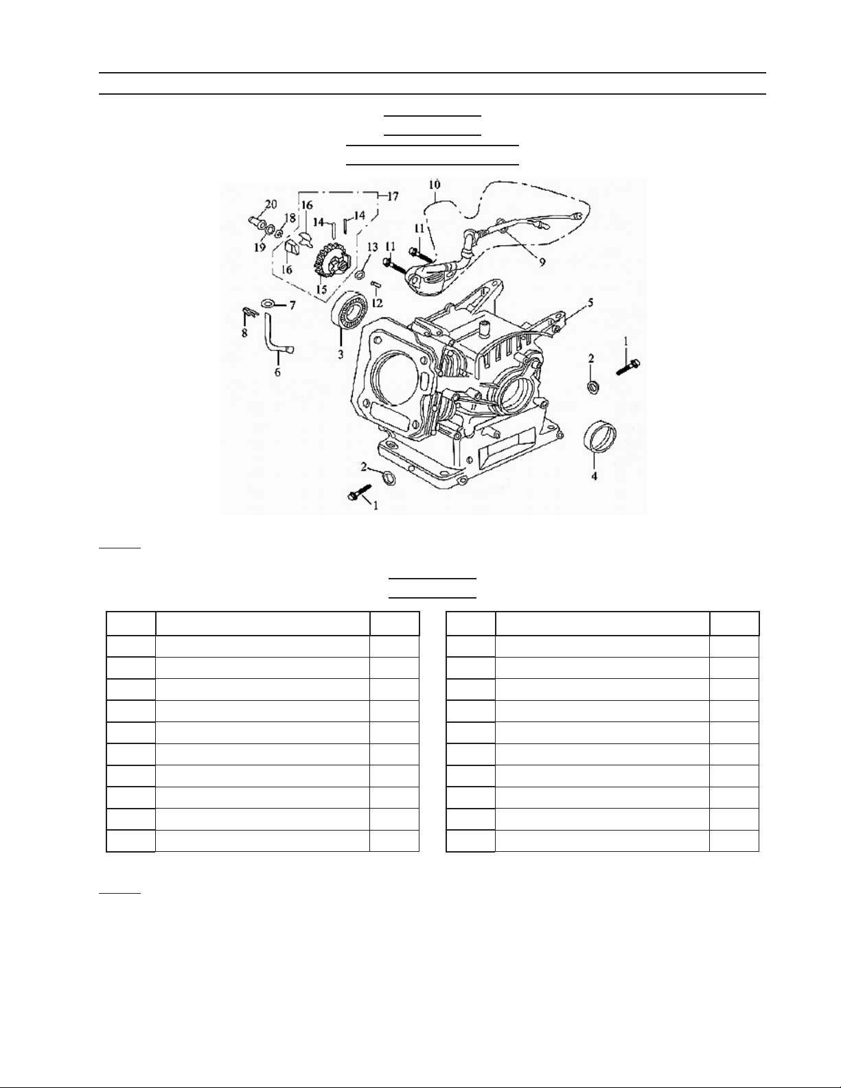
PARTS LISTS AND ASSEMBLY DIAGRAMS
Crankcase
Assembly Diagram
Note: When ordering parts from this list, specify: CRANKCASE ASSEMBLY and the ITEM
No.
Parts List
Part Description Q’ty
1 Drain Plug 2
2 Washer 2
3 Bearing, 6205 1
4 Seal, Oil, Crankshaft 1
5 Crankcase 1
6 Sway Bar, Regulator 1
7 Washer 2
8 Pin, Split 1
9 Nut, M10 1
10 Sensor, Oil 1
Note: Some parts, on this Parts List and the Parts Lists that follow, are listed and shown for
illustration purposes only and are not available individually as replacement parts.
Part Description Q’ty
11 Bolt, M6x14 2
12 Regulating Shaft 1
13 Washer, Drive Gear 1
14 Pin 2
15 Drive Gear, Regulator 1
16 Fly Block 2
17 Drive Gear Assy, Regulator 1
18 Snap Ring 1
19 Washer 2
20 Sliding Sleeve 1
SKU 94187 For technical questions, please call 1-800-444-3353
Page 16
Page 17
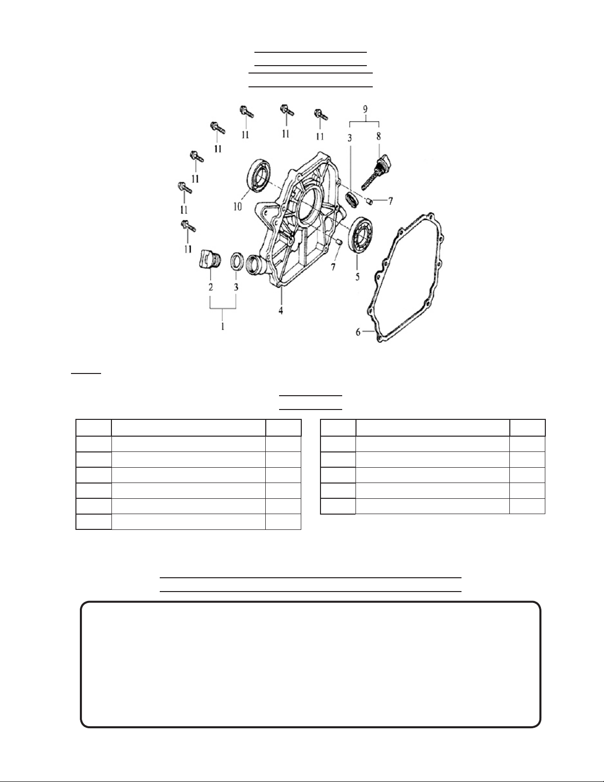
Crankcase Cover
Assembly Diagram
Note: When ordering parts from this list, specify: CRANKCASE COVER ASSEMBLY and the
ITEM No.
Parts List
Part Description Q’ty
1 Oil Plug with Seal 1
2 Oil Plug 1
3 Seal 2
4 Crankcase Cover 1
5 Bearing, 6250 1
6 Gasket, Crankcase 1
Part Description Q’ty
7 Pin, Set 2
8 Dipstick 1
9 Dipstick with seal 1
10 Oil Seal, Crankshaft 1
11 Bolt, M8x32 7
PLEASE READ THE FOLLOWING CAREFULLY
THE MANUFACTURER AND/OR DISTRIBUTOR HAS PROVIDED THE PARTS LIST AND ASSEMBLY DIAGRAM IN THIS MANUAL AS A REFERENCE TOOL ONLY. NEITHER THE MANUFACTURER
OR DISTRIBUTOR MAKES ANY REPRESENTATION OR WARRANTY OF ANY KIND TO THE BUYER
THAT HE OR SHE IS QUALIFIED TO MAKE ANY REPAIRS TO THE PRODUCT, OR THAT HE OR
SHE IS QUALIFIED TO REPLACE ANY PARTS OF THE PRODUCT. IN FACT, THE MANUFACTURER
AND/OR DISTRIBUTOR EXPRESSLY STATES THAT ALL REPAIRS AND PARTS REPLACEMENTS
SHOULD BE UNDERTAKEN BY CERTIFIED AND LICENSED TECHNICIANS, AND NOT BY THE
BUYER. THE BUYER ASSUMES ALL RISK AND LIABILITY ARISING OUT OF HIS OR HER REPAIRS
TO THE ORIGINAL PRODUCT OR REPLACEMENT PARTS THERETO, OR ARISING OUT OF HIS
OR HER INSTALLATION OF REPLACEMENT PARTS THERETO.
SKU 94187 For technical questions, please call 1-800-444-3353
Page 17
Page 18
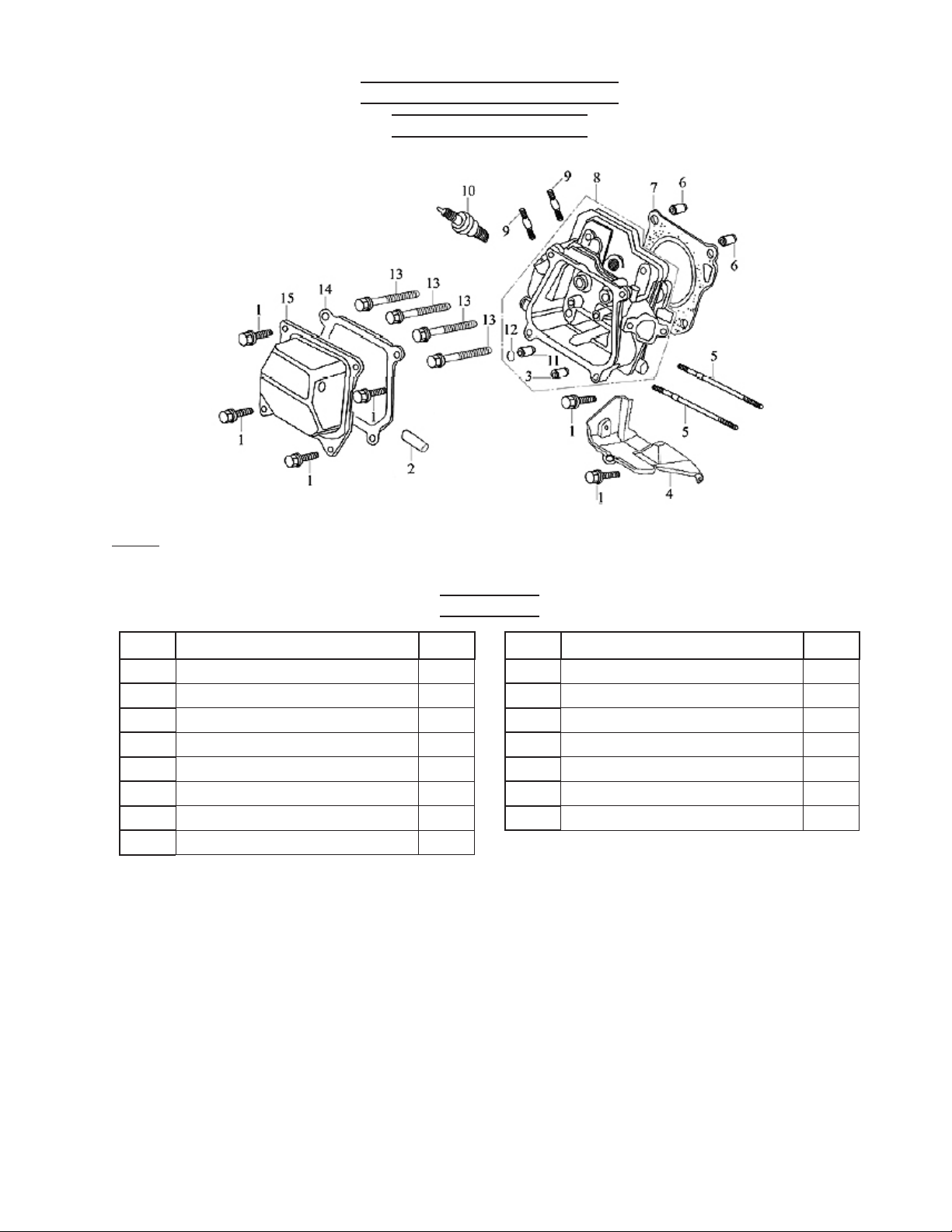
Cylinder Head and Cover
Assembly Diagram
Note: When ordering parts from this list, specify: CYLINDER HEAD AND COVER ASSEMBLY
and the ITEM No.
Parts List
Part Description Q’ty
1 Bolt, M6x12 6
2 Air duct 1
3 Intake Valve Guide 1
4 Lead Wind Cover 1
5 Stud, M6x109 2
6 Pin, Set 10x16 2
7 Gasket, Cylinder Head 1
8 Cylinder Head Assembly 1
Part Description Q’ty
9 Stud, M8x34 2
10 Spark Plug, F6TC 1
11 Exhaust Valve Guide 1
12 Circle Clip 1
13 Bolt 4
14 Gasket, Cylinder Head Cover 1
15 Cylinder Head Cover Assembly 1
SKU 94187 For technical questions, please call 1-800-444-3353
Page 18
Page 19
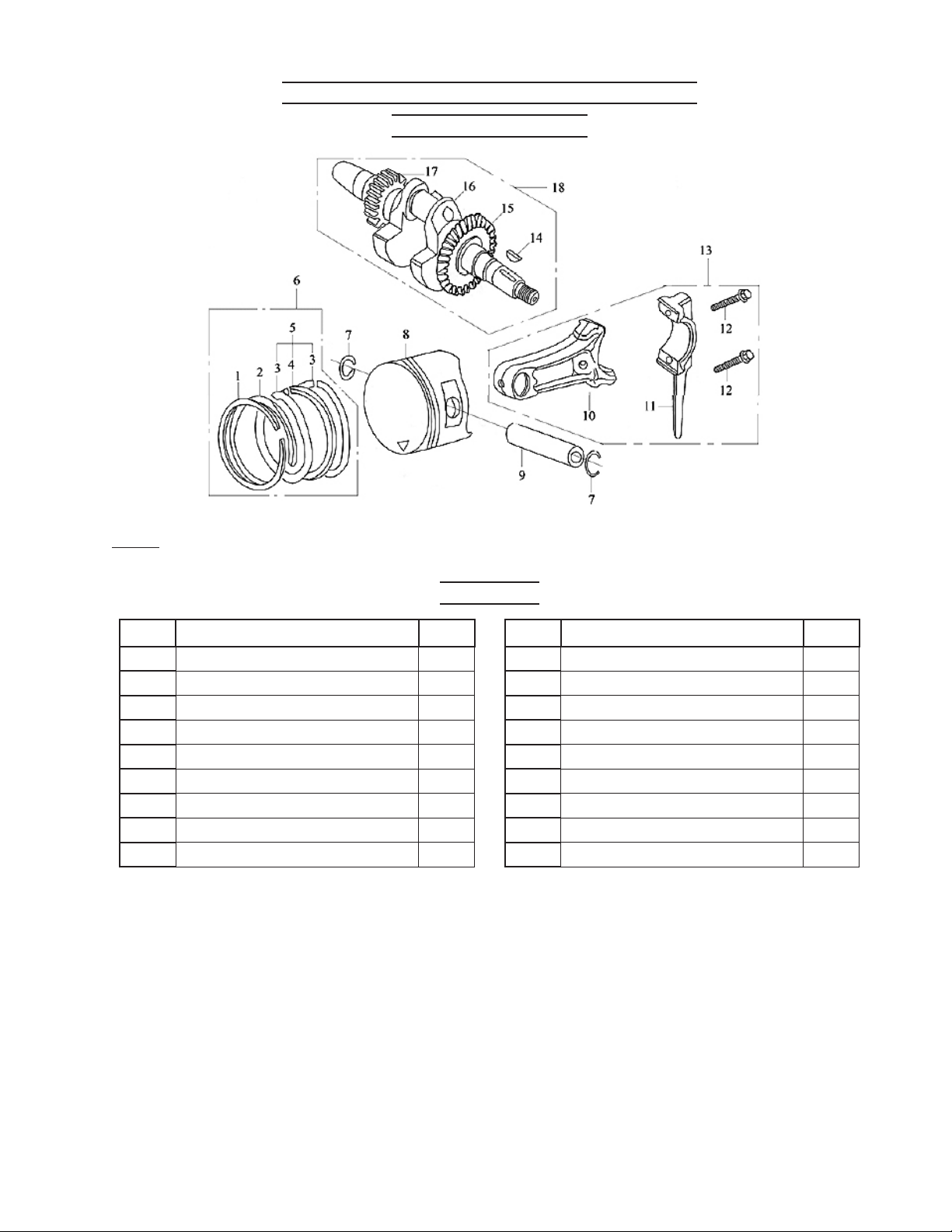
Crankshaft, Piston, and Connecting Rod
Assembly Diagram
Note: When ordering parts from this list, specify: CRANKSHAFT, PISTON, AND CONNECT-
ING ROD ASSEMBLY and the ITEM No.
Parts List
Part Description Q’ty
1 Piston Ring (I) 1
2 Piston Ring (II) 1
3 Side Rail 2
4 Expander 1
5 Scraper Ring Set 1
6 Piston Ring Assembly 1
7 Piston Pin Circle Clip 2
8 Piston 1
9 Piston Pin 1
Part Description Q’ty
10 Connecting Rod 1
11 Connecting Rod Cover 1
12 Bolt 2
13 Connecting Rod Assembly 1
14 Woodruff Key 1
15 Drive Gear 1
16 Crankshaft 1
17 Timing Drive Gear 1
18 Crankshaft Assembly 1
SKU 94187 For technical questions, please call 1-800-444-3353
Page 19
Page 20
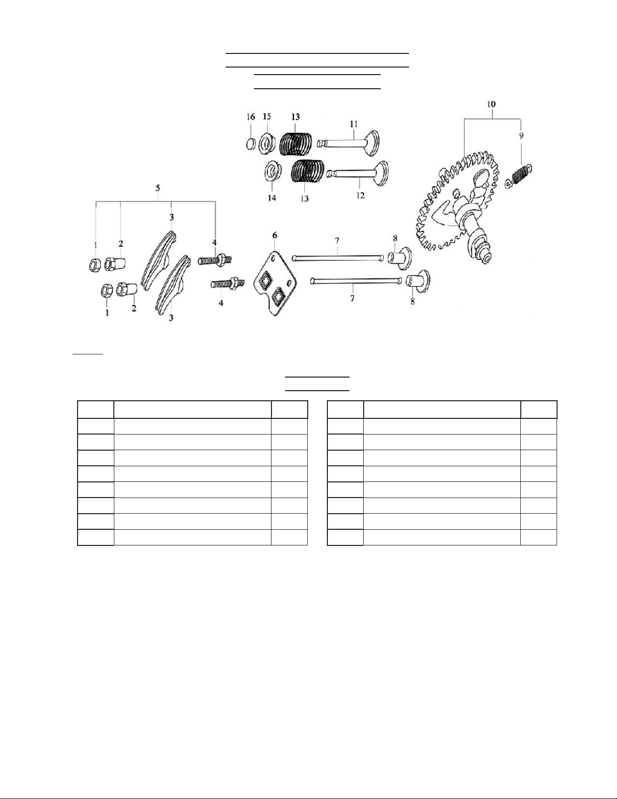
Camshaft and Rocker Valve
Assembly Diagram
Note: When ordering parts from this list, specify: CAMSHAFT AND ROCKER VALVE AS-
SEMBLY and the ITEM No.
Parts List
Part Description Q’ty
1 Lock Nut 2
2 Sleeve 2
3 Valve, Rocker 2
4 Bolt, Adjusting, Valve Gap 2
5 Valve, Rocker, Assembly 2
6 Pusher Guide 1
7 Pusher 2
8 Tappet 2
Part Description Q’ty
9 Spring, Extension 1
10 Camshaft Assembly 1
11 Valve, Exhaust 1
12 Valve, Intake 1
13 Spring, Valve 2
14 Spring Seat, Intake Valve 1
15 Spring Seat, Exhaust Valve 1
16 Cap 1
SKU 94187 For technical questions, please call 1-800-444-3353
Page 20
Page 21
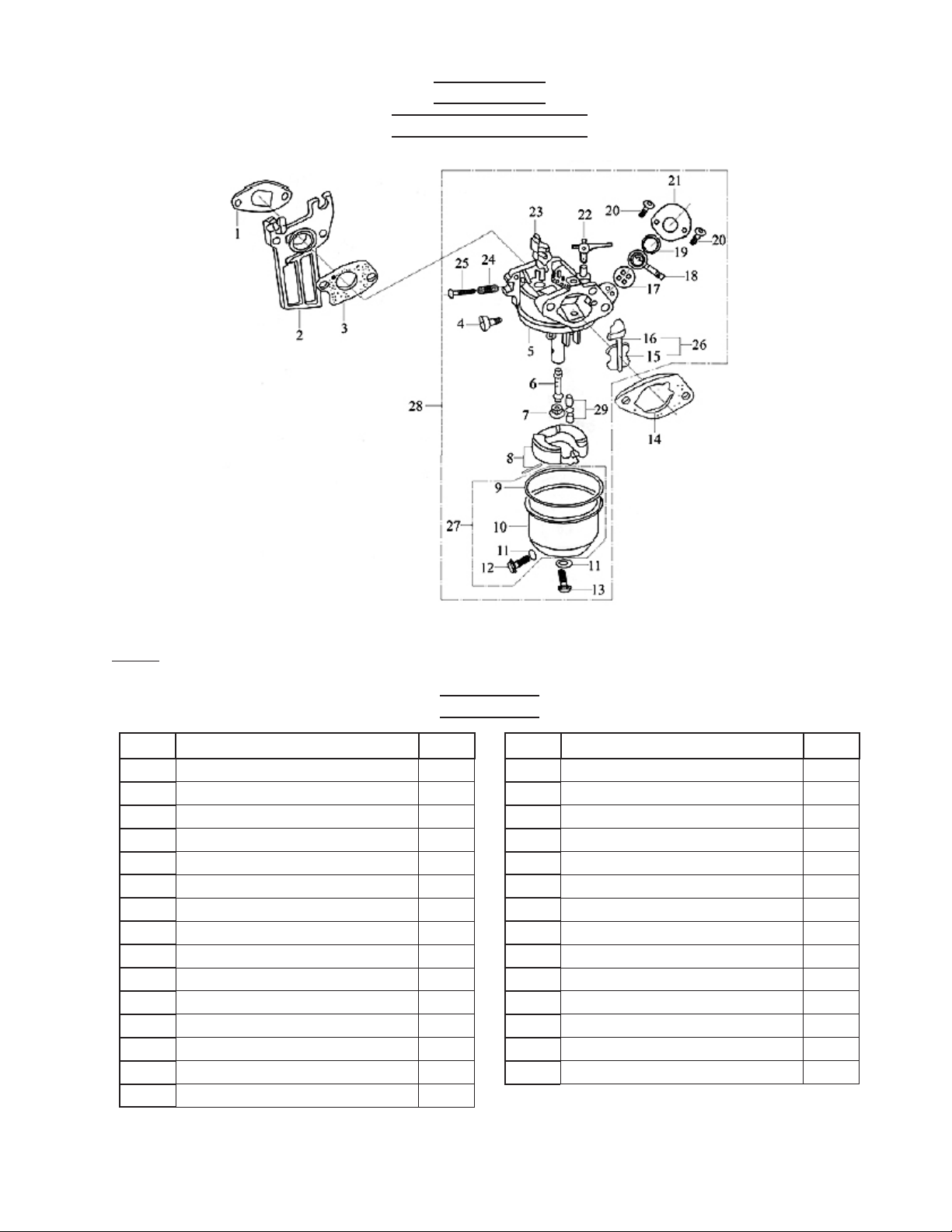
Carburetor
Assembly Diagram
Note: When ordering parts from this list, specify: CARBURETOR ASSEMBLY and the ITEM
No.
Parts List
Part Description Q’ty
1 Inlet Gasket 1
2 Connecting Block 1
3 Carburetor Gasket 1
4 Screw, Idle Adjustment 1
5 Chamber Bode, Mixture 1
6 Nozzle, Main 1
7 Jet, Main 1
8 Float 1
9 Float Chamber Gasket 1
10 Float Chamber 1
11 Washer 2
12 Float Chamber Drain Screw 1
13 Screw 1
14 Air Cleaner Gasket 1
15 Choke 1
Part Description Q’ty
16 Choke Stem 1
17 Washer, Air-proof 1
18 Throttle Lever 1
19 Washer 1
20 Screw, M4 2
21 Cover 1
22 Choke Switch 1
23 Throttle Unit 1
24 Spring, Mixture Adjustment Screw 1
25 Screw, Mixture Adjustment 1
26 Choke Unit 1
27 Float Chamber 1
28 Carburetor Assembly 1
29 Float Needle 1
SKU 94187 For technical questions, please call 1-800-444-3353
Page 21
Page 22
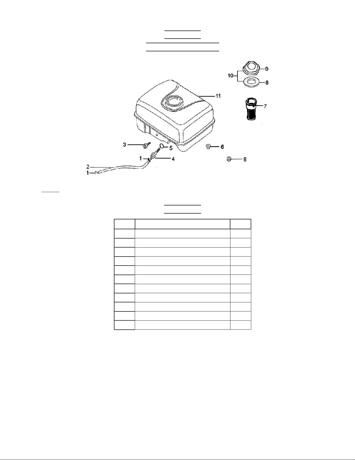
Fuel Tank
Assembly Diagram
Note: When ordering parts from this list, specify: FUEL TANK ASSEMBLY and the ITEM
No.
Parts List
Part Description Q’ty
1 Pipe Clamp 2
2 Pipe, Outlet 1
3 Bolt, M6x22 1
4 Connector 1
5 Packing Ring 1
6 Nut, M6 2
7 Filter Cup 1
8 Packing Ring 1
9 Fuel Filler Cap 1
10 Fuel Filler Cap with Packing Ring 1
11 Fuel Tank 1
SKU 94187 For technical questions, please call 1-800-444-3353
Page 22
Page 23
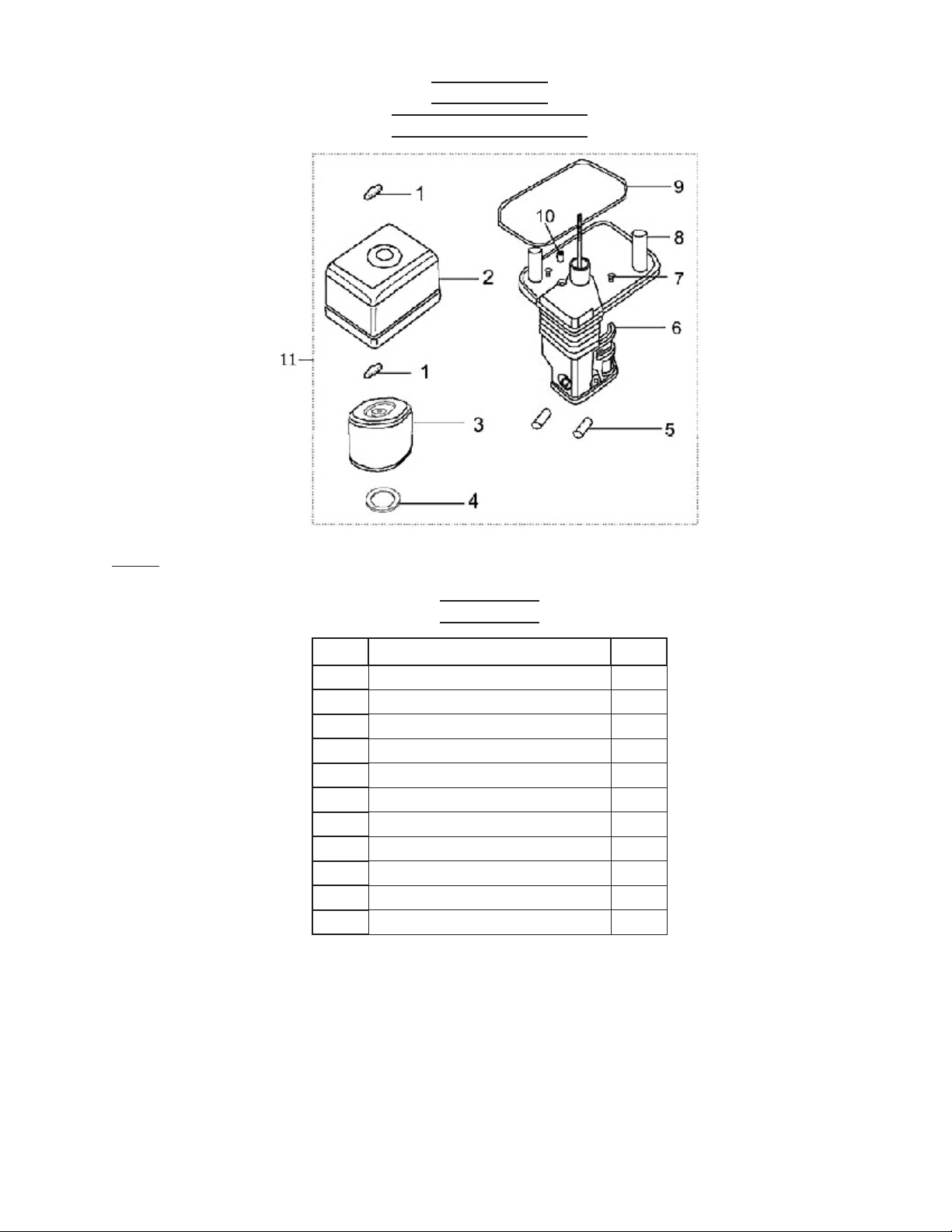
Air Cleaner
Assembly Diagram
Note: When ordering parts from this list, specify: AIR CLEANER ASSEMBLY and the ITEM
No.
Parts List
Part Description Q’ty
1 Wing Nut 2
2 Air Cleaner Cover 1
3 Filter Element 1
4 Washer 1
5 Sleeve A 2
6 Air Cleaner Housing 1
7 Screw, M5x12 2
8 Air Cleaner Base 1
9 Gasket 1
10 Sleeve B 1
11 Air Cleaner Assembly 1
SKU 94187 For technical questions, please call 1-800-444-3353
Page 23
Page 24
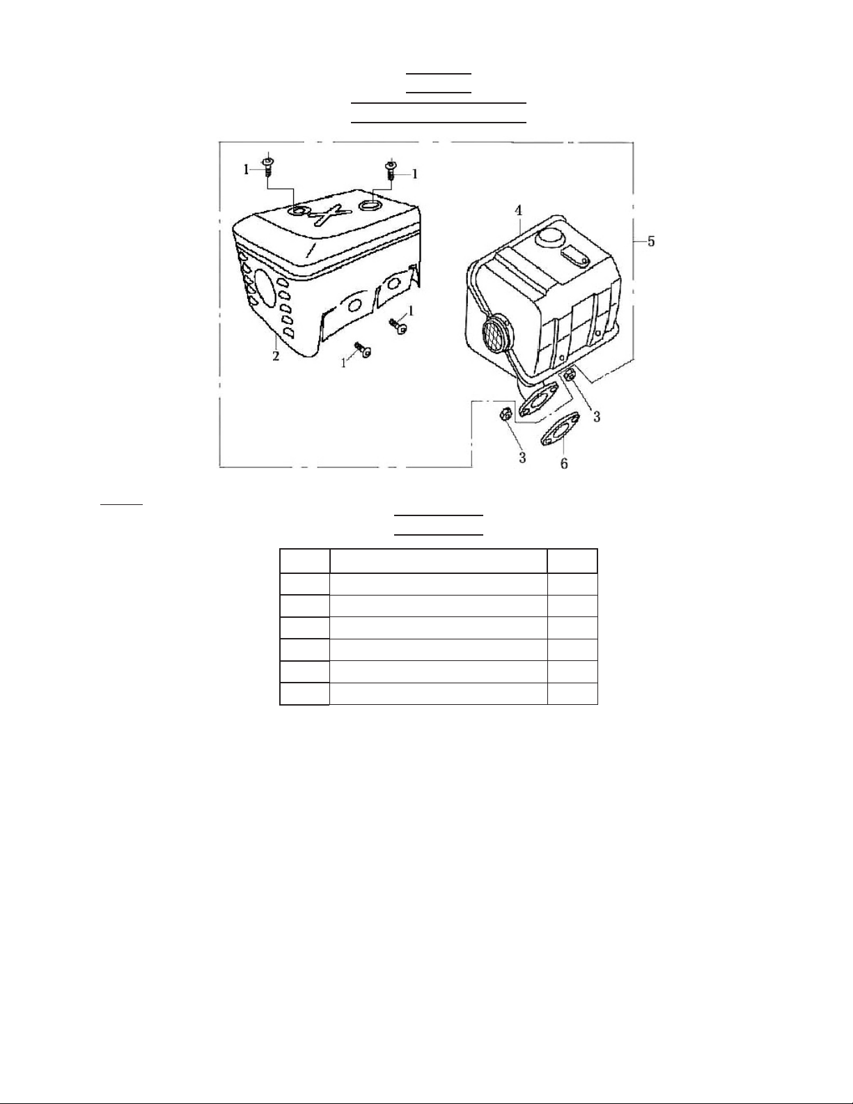
Muffler
Assembly Diagram
Note: When ordering parts from this list, specify: MUFFLER ASSEMBLY and the ITEM No.
Parts List
Part Description Q’ty
1 Screw, M5x8 4
2 Muffler Hood 1
3 Nut, M8 2
4 Muffler 1
5 Exhaust Muffler 1
6 Exhaust Gasket 1
SKU 94187 For technical questions, please call 1-800-444-3353
Page 24
Page 25
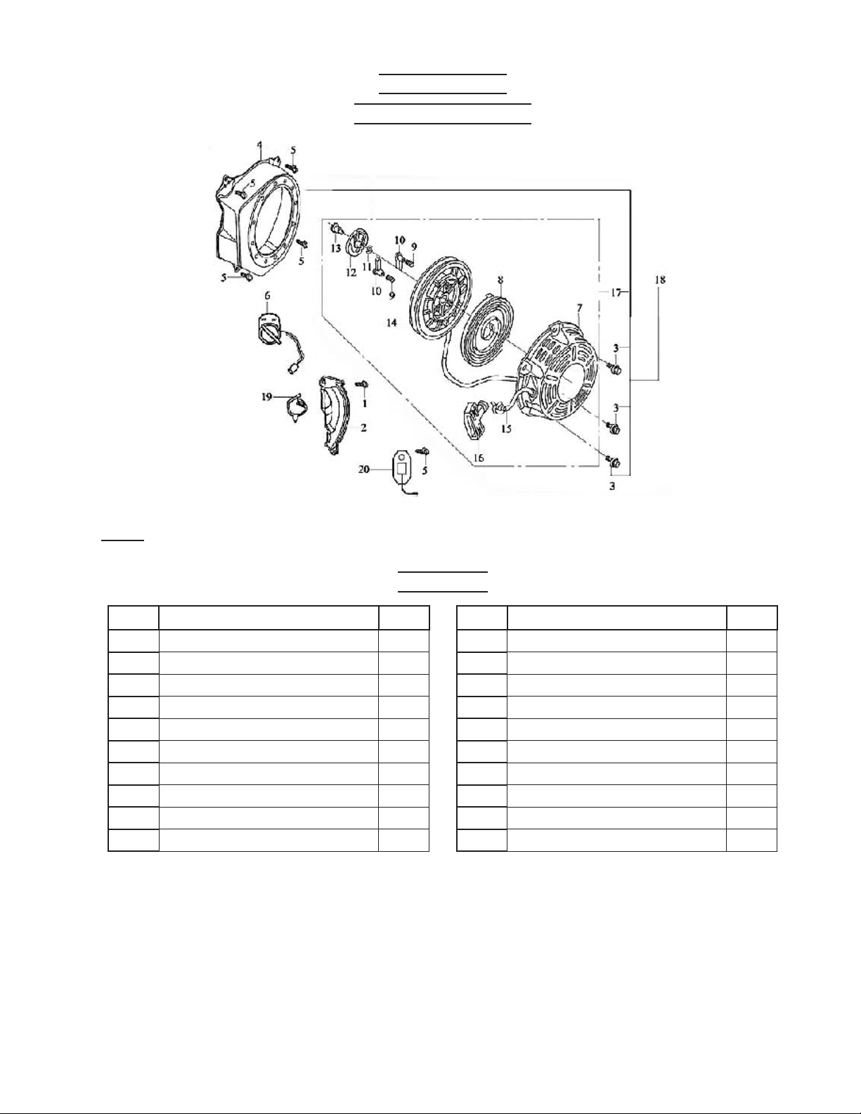
Recoil Starter
Assembly Diagram
Note: When ordering parts from this list, specify: RECOIL STARTER ASSEMBLY and the
ITEM No.
Parts List
Part Description Q’ty
1 Bolt, M6x22 1
2 Crankcase Side Plate Assy 1
3 Bolt, M6x18 3
4 Fan Hood Assy. 1
5 Bolt, M6x12 5
6 Switch, Engine 1
7 Casing 1
8 Spring, Spiral 1
9 Spring, Ratchet 2
10 Ratchet 2
Part Description Q’ty
11 Spring, Friction 1
12 Spring Lid 1
13 Screw, Set 1
14 Starter Wheel 1
15 Rope, Starter 1
16 Handle, Rope Pull 1
17 Recoil Starter 1
18 Recoil Starter Assembly 1
19 Clip, Plastic 1
20 Diode 1
SKU 94187 For technical questions, please call 1-800-444-3353
Page 25
Page 26
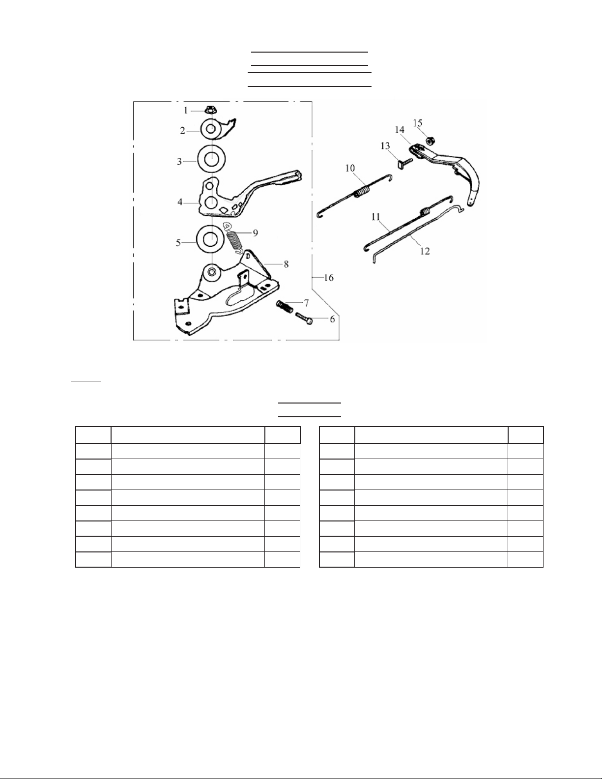
Regulator Control
Assembly Diagram
Note: When ordering parts from this list, specify: REGULATOR CONTROL ASSEMBLY and
the ITEM No.
Parts List
Part Description Q’ty
1 Nut, M6 1
2 Panel, Setting 1
3 Spring Patch 1
4 Hand Grip 1
5 Washer 1
6 Bolt, M5x25 1
7 Spring, Regulating 1
8 Support Panel Assembly 1
Part Description Q’ty
9 Spring 1
10 Spring, Back 1
11 Spring, Fine Regulating 1
12 Rod, Pull 1
13 Bolt, Lock 1
14 Arm, Regulating 1
15 Nut, M6 1
16 Regulating Frame Assembly 1
SKU 94187 For technical questions, please call 1-800-444-3353
Page 26
Page 27
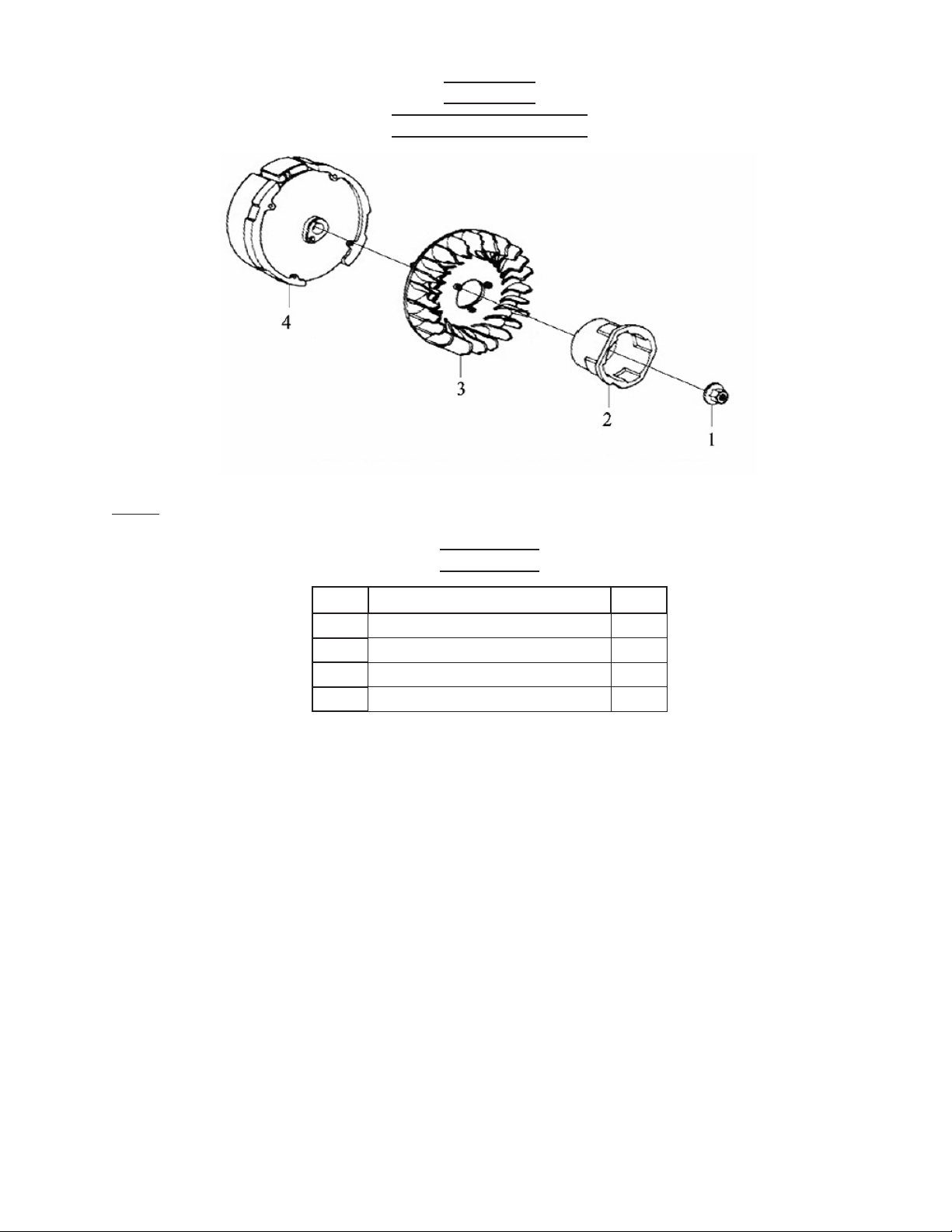
Flywheel
Assembly Diagram
Note: When ordering parts from this list, specify: FLYWHEEL ASSEMBLY and the ITEM
No.
Parts List
Part Description Q’ty
1 Nut, M14x1.5 1
2 Starting Flange 1
3 Flywheel Fan 1
4 Flywheel 1
SKU 94187 For technical questions, please call 1-800-444-3353
Page 27
Page 28
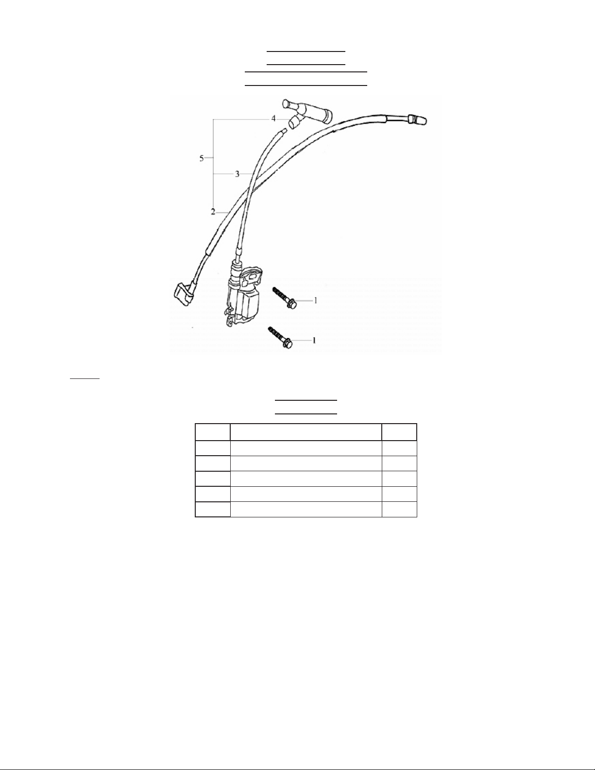
Ignition Coil
Assembly Diagram
Note: When ordering parts from this list, specify: IGNITION COIL ASSEMBLY and the ITEM
No.
Parts List
Part Description Q’ty
1 Screw, M6x22 2
2 Engine Stop Cable 1
3 Ignition Coil 1
4 Spark Plug Cap 1
5 Ignition Coil Assembly 1
SKU 94187 For technical questions, please call 1-800-444-3353
Page 28
Page 29
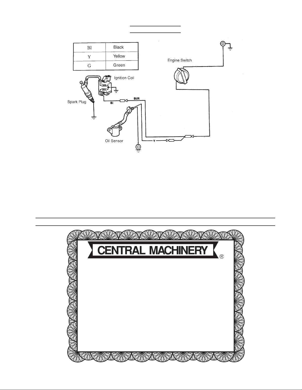
Wiring Diagram
Harbor Freight Tools Co. makes every effort to assure that its products meet high quality and durability standards,
and warrants to the original purchaser that this product is free from defects in materials and workmanship for
the per iod of ninety days from the date of purchase. This warranty does not apply to damage due directly or
indirectly, to misuse, abuse, negligence or accidents, repairs or alterations outside our facilities, or to lack of
maintenance. We shall in no event be liable for death, injuries to persons or property, or for incidental, contingent,
special or consequential damages arising from the use of our product. Some states do not allow the exclusion
or limitation of incidental or consequential damages, so the above limitation of exclusion may not apply to you.
THIS WARRANTY IS EXPRESSLY IN LIEU OF ALL OTHER WARRANTIES, EXPRESS OR IMPLIED,
INCLUDING THE WARRANTIES OF MERCHANTABILITY AND FITNESS.
To take adv antage of this warranty, the product or part must be returned to us with transportation charges
prepaid. Proof of purchase date and an explanation of the complaint must accompany the merchandise. If our
inspection verifies the defect, we will either repair or replace the product at our election or we may elect to
refund the purchase price if we cannot readily and quickly pro vide you with a replacement. We will return
repaired products at our expense, but if we determine there is no defect, or that the defect resulted from
causes not within the scope of our warranty, then you must bear the cost of returning the product.
This warranty gives you specific legal rights and you may also have other rights which vary from state to state.
3491 Mission Oaks Blvd. • PO Box 6009 • Camarillo, CA 93011 • (800) 444-33533491 Mission Oaks Blvd. • PO Box 6009 • Camarillo, CA 93011 • (800) 444-3353
3491 Mission Oaks Blvd. • PO Box 6009 • Camarillo, CA 93011 • (800) 444-33533491 Mission Oaks Blvd. • PO Box 6009 • Camarillo, CA 93011 • (800) 444-3353
3491 Mission Oaks Blvd. • PO Box 6009 • Camarillo, CA 93011 • (800) 444-3353
LIMITED 90 DAY WARRANTY
WARRANTY
SKU 94187 For technical questions, please call 1-800-444-3353
Page 29
Page 30

EMISSION CONTROL SYSTEM WARRANTY
California and United States
Emission Control Defects Warranty
Statement
The California Air Resources Board (herein CARB), the United
States Environmental Protection Agency (herein EPA), and
Harbor Freight Tools® (herein HFT) are pleased to explain
the emission control system warranty on your 1995 and later
Small Off-Road Engine (herein engine). In California, the
engine must be designed, built and equipped to meet the
State’s stringent anti-smog standards. Elsewhere within the
United States, new off-road, spark-ignition engines certified
for model year 1997 and later, must meet similar standards
set forth by the EPA. HFT must warrant the emission control
system on your engine for the periods of time described
below, provided there has been no abuse, neglect or improper
maintenance of your engine.
Your emission control system may include parts such as the
carburetor or fuel-injection system, and the ignition system.
Also included may be hoses, belts, connectors and other
emission-related assemblies.
Where a warrantable condition exists, HFT will repair your
engine at no cost to you including diagnosis, parts and
labor.
Manufacturer’s Warranty Coverage
The 1995 and later engines are warranted for two (2) years.
If any emission-related part on your engine is defective, the
part will be repaired or replaced by HFT.
Harbor Freight Tools Emission
Control Defects Warranty Coverage
Engines are warranted for a period of two (2) years relative
to emission control parts defects, subject to the provisions
set forth below. If any emission related part on your engine is
defective, the part will be repaired or replaced by HFT.
Owner’s Warranty Responsibilities
- As the engine owner, you are responsible for the
performance of the required maintenance listed in your
Owner’s Manual. HFT recommends that you retain all
receipts covering maintenance on your engine, but HFT
cannot deny warranty solely for the lack of receipts or for
your failure to ensure the performance of all scheduled
maintenance.
- As the engine owner, you should, however, be aware
that HFT may deny you warranty coverage if your engine
or a part has failed due to abuse, neglect, improper
maintenance, or unapproved modifications.
- You are responsible for shipping your engine to a HFT
warranty station as soon as a problem exists. Contact
the HFT Customer Service department at the number
below to make shipping arrangements. The warranty
repairs should be completed in a reasonable amount of
time, not to exceed 30 days.
If you have any questions regarding your warranty rights and
responsibilities, you should contact the Harbor Freight Tools
Customer Service Department at 1-800-444-3353.
Harbor Freight Tools Emission
Control Defects Warranty
Provisions
1. Length of Coverage
HFT warrants to a first retail purchaser and each
subsequent purchaser that the engine is free from defects
in materials and workmanship that cause the failure of
warranted parts for a period of two (2) years after the
date of delivery to the first retail purchaser.
2. No Charge Repair or Replacement
Repair or replacement of any warranted part will be
performed at no charge to the owner if the work is
performed through a warranty station authorized by
HFT. For emissions warranty service, contact the HFT
Customer Service Department at 1-800-444-3353.
3. Consequential Damages Coverage
Coverage under this warranty shall also extend to the
failure of any engine components caused by the failure
of any warranted part while it is still covered under this
warranty.
Equivalent in durability and performance, may be used
in performance of maintenance or repairs. The owner
is responsible for commissioning a qualified technician/
mechanic to perform all required maintenance, as
outlined in the Inspection, Cleaning, and Maintenance
section in this manual.
SKU 94187 For technical questions, please call 1-800-444-3353
Page 30
Page 31

EMISSION CONTROL SYSTEM WARRANTY (CONTINUED)
4. Coverage Exclusions
Warranty claims shall be filed in accordance with the
provisions of the HFT warranty policy explained in the box
at the top of the previous page. HFT shall not be liable for
any loss of use of the engine, for any alternative usage,
for any damage to goods, loss of time, or inconvenience.
Warranty coverage shall also be excluded for any part
which fails, malfunctions, or is damaged due to failure
to follow the maintenance and operating instructions set
forth in the Owner’s Manual including, but not limited
to:
(a) use of parts which are not authorized by HFT
(b) improper installation, adjustment or repair of the
engine or of any warranted part unless performed
by an authorized warranty center
(c) failure to follow recommendations on fuel use
contained in the Owner’s Manual
(d) improper or in adequat e maint enance of any
warranted parts
(e) repairs performed outside of the authorized warranty
service dealers
(f) alterations by changing, adding to or removing parts
from the engine.
5. Service and Maintenance
Component parts which are not scheduled for replacement
as required maintenance or are scheduled only for
regular inspection to the effect of “repair or replace as
necessary” are warranted for the warranty period. Any
warranted part which is scheduled for replacement as
required maintenance is warranted for the period of
time up to the first scheduled replacement point for that
part. Any replacement part, provided it is equivalent in
durability and performance, may be used in performance
of maintenance or repairs. The owner is responsible
for commissioning a qualified technician/mechanic to
perform all required maintenance, as outlined in the
Inspection, Cleaning, and Maintenance section on
page 17 of this manual.
6. Warranted Parts
1) Fuel Metering System
i) Carburetor and its internal parts.
ii) Fuel pump (if so equipped).
iii) Cold start enrichment system.
2) Air Induction System
i) Intake pipe/manifold.
ii) Air cleaner.
3) Ignition System
i) Spark plug.
ii) Magneto ignition system.
4) Catalyst System (if so equipped)
i) Exhaust pipe stud.
ii) Muffler.
iii) Catalytic converter (if so equipped).
5) Miscellaneous items Used in Above Systems
i) Vacuum, temperature and time sensitive valves
and switches.
ii) Hoses, belts, connectors, and assemblies.
SKU 94187 For technical questions, please call 1-800-444-3353
Page 31
 Loading...