

Page 1
®
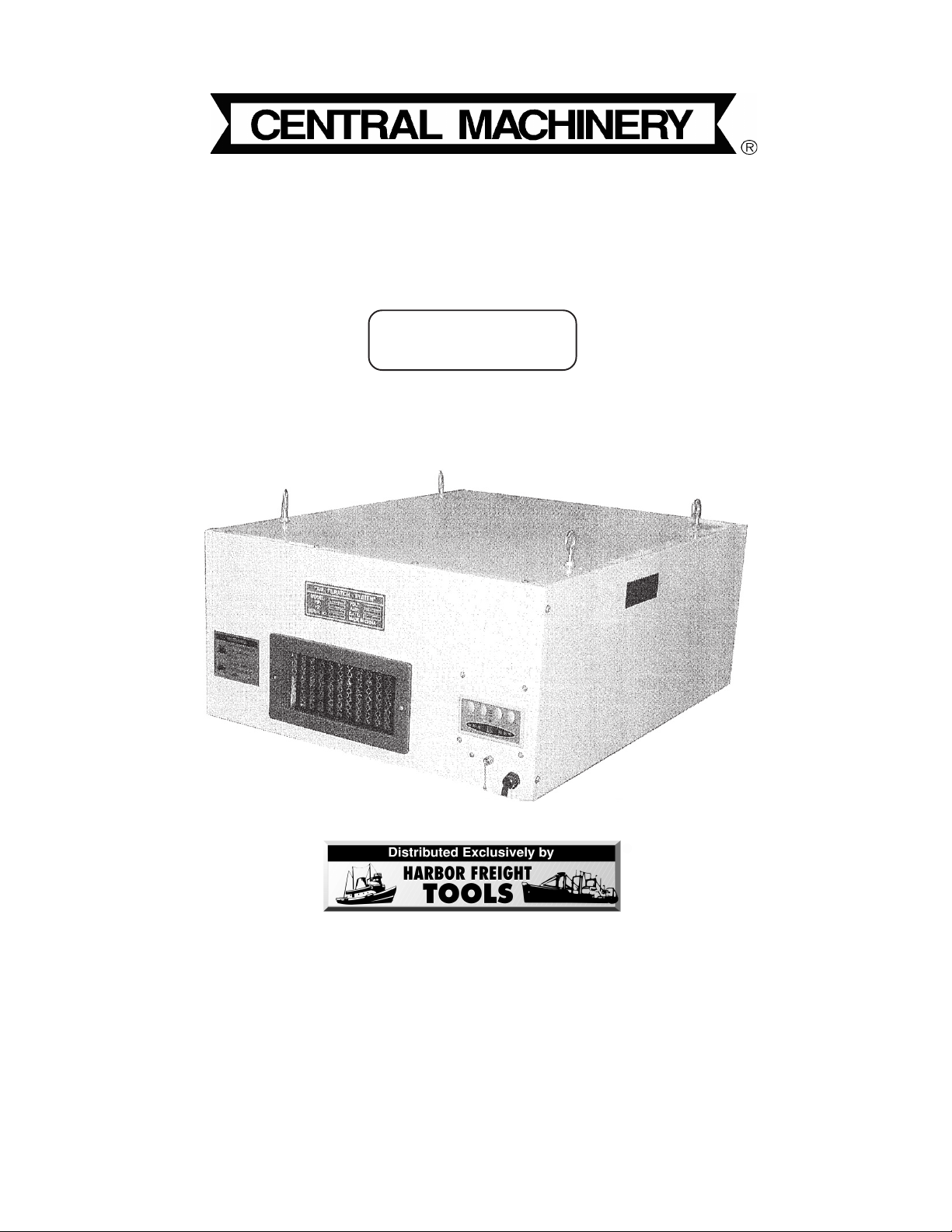
AIR FILTRATION SYSTEM
WITH REMOTE CONTROL
Model 91393
ASSEMBLY AND OPERATING INSTRUCTIONS
3491 Mission Oaks Blvd., Camarillo, CA 93011
Visit our Web site at: http://www.harborfreight.com
Copyright© 2004 by Harbor Freight Tools®. All rights reserved. No portion of this
manual or any artwork contained herein may be reproduced in any shape or form
without the express written consent of Harbor Freight Tools.
For technical questions, please call 1-800-444-3353.
Page 2
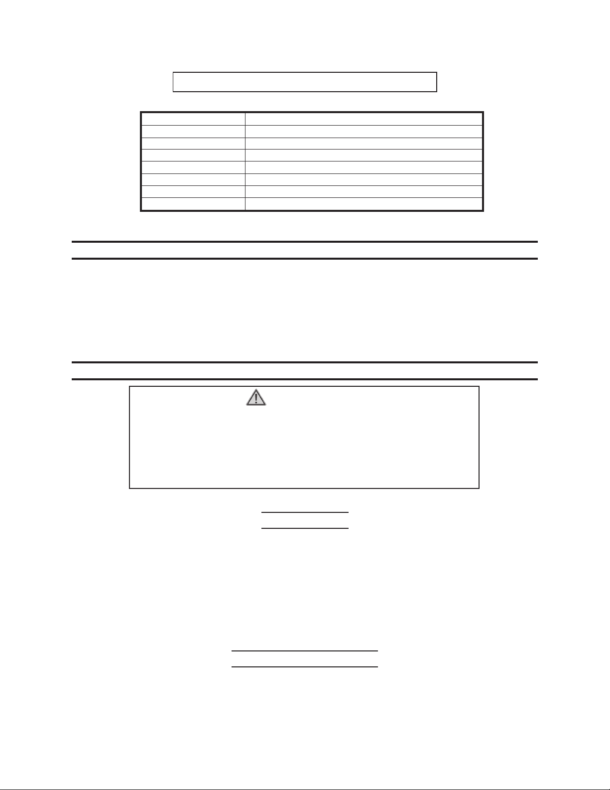
PRODUCT SPECIFICATIONS
Motor
Overall Dimensions 30-1/8” x 24” x 12- 1/8”
Outer and Inner Filter 5 Microns
Noise 50-60 dB
Air Flow High Speed - 360 CFM, Low Speed - 230 CFM
Weight 66 Lbs.
Po wer Cord 5’ 3” L, 3-Prong, UL Listed
Remote Control Uses 2 “AAA” Batteries (included)
1
/6 HP, 115 V, 60 Hz, 1 Phase
SA VE THIS MANUAL
You will need this manual for the safety warnings and precautions, assembly, operating, inspection, maintenance and cleaning procedures, parts list and
assembly diagram. Keep your invoice with this manual. Write the invoice number
on the inside of the front cover. Keep this manual and invoice in a safe and dry
place for future reference.
GENERAL SAFETY RULES
WARNING!
READ AND UNDERSTAND ALL INSTRUCTIONS
Failure to follow all instructions listed below may result in
electric shock, fire, and/or serious injury.
SA VE THESE INSTRUCTIONS
WORK AREA
1. Keep your w ork area clean and well lit. Cluttered benches and dark areas invite
accidents.
2. Do not operate electric products in explosive atmospheres, such as in the
presence of flammable liquids, gases, or dust.
3. Keep bystanders, children, and visitors away while mounting or maintaining
the Air Filtration System.
ELECTRICAL SAFETY
4. Grounded products must be plugged into an outlet properly installed and
grounded in accordance with all codes and ordinances. Never remove the
SKU 91393 PAGE 2
Page 3

grounding prong or modify the plug in an y way . Do not use any adapter plugs.
Check with a qualified electrician if you are in doubt as to whether the outlet
is properly gr ounded. If the product should electrically malfunction or break down,
grounding provides a low resistance path to carry electricity away from the user.
5. Double insulated products are equipped with a polarized plug (one blade is
wider than the other). This plug will fit in a polarized outlet only one way. If
the plug does not fit fully in the outlet, re ver se the plug. If it still does not fit,
contact a qualified electrician to install a polarized outlet. Do not change the
plug in any way. Double insulation eliminates the need for the three wire
grounded power cord and grounded power supply system.
6. Av oid body contact with grounded surfaces suc h as pipes, radiator s, ranges,
and refrigerators. There is an increased risk of electric shock if your body is
grounded.
7. Do not expose this product to rain or wet conditions. W ater entering an electric
product will increase the risk of electric shock.
8. Do not abuse the P ower Cord. N ever use the P ower Cord to carry the pr oduct
or pull the Plug from an outlet. Keep the Power Cord away from heat, oil,
sharp edges, or moving parts. Replace damaged Power Cords immediately.
Damaged Power Cords increase the risk of electric shock.
PERSONAL SAFETY
9. Stay alert. W atch what you are doing, and use common sense when operating
a power product. Do not use a power product while tired or under the influence
of drugs, alcohol, or medication.
10. Dress properly. Do not wear loose clothing or jewelry. Contain long hair.
Keep your hair, clothing, and gloves away from moving parts. Loose clothes,
jewelry, or long hair can be caught in moving parts.
11. Av oid accidental starting. Be sure the Po wer Switch is off before plugging in.
12. Use safety equipment. Always wear eye protection. During installation and
maintenance use non-skid safety shoes and ANSI approved safety goggles.
TOOL USE AND CARE
13. Use the correct product for y our application. The correct product will do the job
better and safer at the rate for which it is designed.
14. Do not use the power product if the Power Switch does not turn it on or off.
Any product that cannot be controlled with the P ower Switch is dangerous and must
be replaced.
15. Disconnect the Power Cord Plug from the power source before storing the
system.
SKU 91393 PAGE 3
Page 4

16. Store idle products out of reach of children and other untrained persons.
Products are dangerous in the hands of untrained users.
17. Maintain products with care. Keep products clean. Do not use a damaged
product. Tag damaged products “Do not use” until repaired.
18. Check for misalignment or binding of moving parts, breakage of parts, and
any other condition that may affect the pr oduct’ s operation. If damaged, have
the product serviced before using. Many accidents are caused by poorly
maintained products.
SER VICE
20. Product service must be performed onl y by qualified repair personnel. Service
or maintenance performed by unqualified personnel could result in a risk of injury.
21. When servicing a product, use only identical replacement parts. Follow
instructions in the
manual. Use of unauthor ized parts or failure to follow maintenance instructions
may create a risk of electric shock or injury.
“Inspection, Maintenance, And Cleaning”
section of this
SPECIFIC SAFETY RULES
1. Maintain labels and nameplates on the Air Filtration System. These carry
important information. If unreadable or missing, contact Harbor Freight Tools for a
replacement.
2. Maintain a safe working en vironment. Mak e sure there is adequate surrounding
workspace. Alw a ys keep the w ork area free of obstructions, grease, oil, trash, and
other debris. Do not use a power products in areas near flammable chemicals,
dusts, and vapors. Do not use this product in a damp or wet location.
3. If placing this Air Filtration System on a table or shelf, make sure that the
machine is placed securely on a flat, level surface, capable of supporting the
weight of the machine.
4. If attaching the Air Filtration System to a ceiling, make sure the machine is
attached securely to joists capable of supporting the weight of the machine.
5. Make sure the Switch is in the “Off” position before plugging in the power
cord.
6. Keep the Pleated T ype Filter (1) and the 3-P ocket Type Filter (2) clean, in place,
and in good working order.
7. Always unplug the Air Filtration System from its electrical outlet before
performing any inspection, maintenance, or c leaning procedures.
SKU 91393 PAGE 4
Page 5

ADDITIONAL W ARNINGS
GROUNDING
WARNING!
Improperly connecting the grounding wire can result in the risk of electric
shock. Check with a qualified electrician if you are in doubt as to whether the
outlet is properly grounded. Do not modify the power cord plug provided with
the product. Never remove the grounding prong from the plug. Do not use the
product if the power cord or plug is damaged. If damaged, have it repaired by
a service facility before use. If the plug will not fit the outlet, have a proper
outlet installed by a qualified electrician.
GROUNDED PRODUCT: PRODUCTS WITH THREE PRONG PLUGS
1. Products marked with “Grounding Required” have a three wire cord and three
prong grounding plug. The plug must be connected to a properly grounded
outlet. If the product should electrically malfunction or break down, grounding
provides a low resistance path to carry electricity away from the user, reducing
the risk of electric shock. (See Figure A.)
2. The grounding prong in the plug is connected through the green wire inside the
cord to the grounding system in the tool. The green wire in the cord must be the
only wire connected to the product’s grounding system and must never be
attached to an electrically “live” terminal. (See Figure A.)
3. Your product must be plugged into an appropriate outlet, properly installed and
grounded in accordance with all codes and ordinances. The plug and outlet
should look like those in the following illustration. (See Figure A.)
FIGURE A
SKU 91393 PAGE 5
Page 6

DOUBLE INSULATED PRODUCTS: PRODUCTS WITH TWO PRONG PLUGS
4. Products marked “Doub le Insulated” do not require g rounding. They ha ve a special
double insulation system which satisfies OSHA requirements and complies with
the applicable standards of Underwriters Laboratories, Inc., the Canadian Stan-
dard Association, and the National Electrical Code. (See Figure B.)
5. Double insulated products may be used in either of the 120 volt outlets shown in
the following illustration. (See Figure B.)
FIGURE B
EXTENSION CORDS
1.
2. As the distance from the supply outlet increases, you must use a heavier gauge
3. The smaller the gauge number of the wire, the greater the capacity of the cord.
4. When using more than one extension cord to make up the total length, make
Grounded
can use either a two or three wire extension cord.
extension cord. Using extension cords with inadequately sized wire causes a
serious drop in voltage, resulting in loss of pow er and possible product damage.
(See Figure C, next page.)
For e xample, a 14 gauge cord can carry a higher current than a 16 gauge cord.
(See Figure C.)
sure each cord contains at least the minimum wire size required.
(See Figure C.)
tools require a three wire extension cord.
Double Insulated
tools
5. If you are using one extension cord for more than one product, add the name
plate amperes and use the sum to determine the required minimum cord size.
(See Figure C.)
SKU 91393 PAGE 6
Page 7

6. If you are using an extension cord outdoors, make sure it is marked with the suffix
“W-A” (“W” in Canada) to indicate it is acceptable for outdoor use.
7. Make sure your extension cord is properly wired and in good electrical condition.
Always replace a damaged extension cord or have it repaired by a qualified
electrician before using it.
8. Protect your extension cords from sharp objects, excessive heat, and damp or
wet areas.
FIGURE C
V ~
A
n
o
xxxx/min.
SYMBOLOGY
Double Insulated
Canadian Standards
Association
Underwriters
Laboratories, Inc.
Volts Alternating Current
Amperes
No Load Revolutions
per Minute (RPM)
SKU 91393 PAGE 7
Page 8

UNPACKING
When unpacking, check to make sure all the par ts shown on the Parts List on
page 12 are included. If any parts are missing or broken, please call Harbor Freight Tools
at the number shown on the cover of this manual as soon as possible.
ASSEMBLY AND OPERATING INSTRUCTIONS
NOTE: For additional information regarding the parts listed in the following pages, refer
to the
CAUTION: Always make sure the Power Cord of the Air Filtration System is unplugged
Note: If placing this Air Filtration System on a table or shelf, make sure that the
Assembly Diagram on page 13.
from its electrical outlet
machine is placed securely on a flat, level surface, capable of supporting the
weight of the machine.
prior
to making any adjustments to the product.
Note: If attaching the Air Filtration System to a ceiling, make sure the machine is
attached securely to joists capable of supporting the weight of the machine.
1. Locate the desired ceiling location and ceiling joists, upon which to attach the Air
Filtration System.
2. With assistance or lifting equipment (not included), raise the unit to the desired
location. Caution: Make sure other people or pets are well clear of the area during
this procedure.
3. Align the four Hangers (32) (see the
joists and measure for hook bolt location. Insert four hook bolts (not included)
through the ceiling into the underside of the ceiling joists.
Note: The hook bolts must be capable of supporting the weight of the Air Filtration
System, and be of compatible size with the Hangers (32). When hanging the
unit, make sure each Hanger (32) fits completely ov er the end of each hook bolt to
ensure a safe mounting of the Air Filtration System.
Assembly Drawing
on page 13) with the ceiling
SKU 91393 PAGE 8
Page 9

Red Standby
Mode Indicator
FIGURE 2FIGURE 1
Speed
Indicators
Timer
Indicators
Pull
Chain (34)
CONTROL OPERATION
Note: These instructions apply to both the manual controls and the remote control. See
Figures 1 and 2.
1. The Pull Chain (34) under the control panel switches between standby mode and
totally off. When in standby mode the unit will operate when the on/off b utton on the
remote or the panel is pressed. The Chain may break if pulled hard or abruptly.
This Chain may be used to stop the Air Filter System in the e vent of an emergency.
2. Press the “On/Off” button to activate the unit from standby mode. It switches on at
high power initially.
3. Press the “Speed” button once f or high power , twice for medium, and three times f or
low power. The three lights referred to as “Speed Indicators” in Figure 1 indicate,
from left to right; high, medium, and low speed.
4. Press the “Timer” button once for 2 hour automatic shut off, or twice for 4 hour
automatic shut off. The three lights referred to as “Timer Indicators” in Figure 1
indicate, from left to right; on contin uously (no timer), 2 hour timer, and 4 hour timer .
5. The lights between the Speed and Timer Buttons indicate the speed that the unit is
operating at. The faster the speed is the faster these lights flash.
6. To turn off the unit manually, press the Off button.
Note: To change batteries in the Remote Control (35); remove the bac k panel, replace the
two “AAA” batteries, then replace the back panel.
SKU 91393 PAGE 9
Page 10

INSPECTION, MAINTENANCE, AND CLEANING
1. WARNING! Make sure the Switch Box (19) of the Air Filtration System is in its
“OFF” position and that the product is unplugged from its electrical outlet before
performing any inspection, maintenance, or cleaning procedures .
2. BEFORE EACH USE, inspect the general condition of the Air Filtration System.
Check for loose screws, misalignment or binding of moving parts, cracked or bro-
ken parts, damaged electrical wiring, and any other condition that may affect its
safe operation. If abnormal noise or vibration occurs, have the problem corrected
before further use. Do not use damaged equipment.
3. Periodically, inspect the Pleated Type Filter (1) for dirt and debris, and if necessary ,
remove and change the Pleated Type Filter (1). On the rear of the unit lift the
Pleated Type Filter (1) so that its bottom edge clears the bottom lip of the opening.
Swing the bottom out and remove the Pleated Type Filter (1) and inspect it to see
whether it needs a simple cleaning, or it needs replacement. Reinsert the Pleated
Type Filter (1). See FIGURE 3.
FIGURE 3
Pleated Type
Filter (1)
3-Pocket Type
Filter (2)
Note: During this procedure, wear ANSI approved safety goggles and a dust mask.
4. Periodically, inspect the 3-Poc ket T ype Filter (2) f or dirt and debris, and if necessary ,
remove and change the 3-Pocket Type Filter (2). Remove the Pleated Type Filter
(1), as explained above. Then, remove the 3-Pocket Type Filter (2) the same way
and inspect it. If necessary, use compressed air to blow dirt and debris from the 3-
Pocket Type Filter (2). Replace the 3-Pocket Type Filter (2) and the Pleated Type
Filter (1) in the rear of the unit. See FIGURE 3.
Note: Replacement filters are availab le from Harbor Freight:
ITEM 91524 - Pleated Type Filter (also part 1)
ITEM 91516 - 3-Pocket Type Filter (also part 2)
SKU 91393 PAGE 10
Page 11

Troubleshooting
Note: Any repairs suggested below should be completed by an authorized service
technician.
Trouble Probable Cause Correction
Motor does not run
when power switch
is pressed on.
Motor does not run
at full speed.
Motor will not reach
full power.
Motor overheats. 1. Using wrong voltage.
Insufficient suction
power.
1. Blo wn fuse .
2. Switch is burned out.
3. Connection wire is
loose or damaged.
1. Power voltage is too low.
2. Motor is damaged.
1. Incorrect power wiring.
2. Overload.
2. Motor is damaged.
1. Inlet port blocked.
2. 3-Pocket Type Filter is
full.
3. Outlet port blocked.
1. Replace fuse.
2. Replace the Switch.
3. Tighten or replace
the wire.
1. Test voltage.
2. Check and repair motor.
1. Have the unit rewired
professionally.
2. Reduce load by cleaning filters as necessary.
1. Verify that the outlet is
115 V A C.
2. Check and repair the
motor.
1. Clean inlet port.
2. Empty 3-Pocket Type
Filter.
3. Clean the outlet port or
adjust the direction of
the outlet.
Unit is shaking. 1. The unit isn’t properly
anchored.
2. The unit isn’t level.
3. Worn or damaged
power cord.
SKU 91393 PAGE 11
1. Mount the unit firmly.
2. Level the unit.
3. Repair or replace
power cord.
Page 12

PARTS LIST
traPnoitpircseD.ytQtraPnoitpircseD.ytQ
1retliFepyTdetaelP202wercSdaeHdnuoR4
2retliFepyTtekcoP-3212wercSxeH6
4wercSdaeHssorC822teNytefaS1
5gnisuoHnaF132llirGteltuO1
6edalBnaF142wercS2
7etalPediuGriA272wercSdaeHxeH61
8droCrewoP182wercSdaeHdnuoR2
01tuN192rehsaW4
21gnihsuB103tuN4
31resnednoC113eldnaH2
41rotoM123regnaH4
51gnihsuB433tuN4
61wercSteS143niahClluP1
71tenibaCniaM153lortnoCetomeR1
81revieceR163daPrebbuR4
91xoBhctiwS1
PLEASE READ THE FOLLOWING CAREFULLY
THE MANUFACTURER AND/OR DISTRIBUTOR HAS PROVIDED THE PARTS LIST AND
ASSEMBLY DIAGRAM IN THIS MANUAL AS A REFERENCE TOOL ONLY. NEITHER THE
MANUF ACTURER OR DISTRIBUT OR MAKES ANY REPRESENT A TION OR W ARRANTY OF ANY KIND
TO THE BUYER THAT HE OR SHE IS QUALIFIED TO MAKE ANY REPAIRS TO THE PRODUCT, OR
THAT HE OR SHE IS QUALIFIED TO REPLACE ANY PARTS OF THE PRODUCT. IN FACT, THE
MANUF A CTURER AND/OR DISTRIBUT OR EXPRESSLY ST ATES THAT ALL REPAIRS AND PARTS
REPLACEMENTS SHOULD BE UNDERTAKEN BY CERTIFIED AND LICENSED TECHNICIANS, AND
NOT BY THE BUYER. THE BUYER ASSUMES ALL RISK AND LIABILITY ARISING OUT OF HIS OR
HER REPAIRS TO THE ORIGINAL PRODUCT OR REPLACEMENT PARTS THERETO, OR ARISING
OUT OF HIS OR HER INST ALLA TION OF REPLACEMENT PARTS THERET O.
SKU 91393 PAGE 12
Page 13

ASSEMBLY DIAGRAM
NOTE: Some parts are listed and shown for illustration purposes only, and are not
available individually as replacement parts.
SKU 91393 PAGE 13
 Loading...