

Page 1
SELF-LEVELING
®
CROSS LASER LEVEL
91179
ASSEMBLY AND OPERATING INSTRUCTIONS
3491 Mission Oaks Blvd., Camarillo, CA 93011
Visit our Web site at http://www.harborfreight.com
Copyright© 2004 by Harbor Freight Tools®. All rights reserved. No por tion of this
manual or any artwork contained herein may be reproduced in any shape or form
without the express written consent of Harbor Freight Tools.
For technical questions and replacement parts, please call 1-800-444-3353
Page 2

Specifications
noitcurtsnoCgnisuoHSBA,leetSnobraCwoL
serutaeF,rosneSleveLni-tliuB/wresaLeniLssorCgnileveL-fleS
kcoLmuludneP
ylppuSrewoP)dedulcnI(3.ytQ-seirettaB”AA“
seducnItiK,seirettaB”AA”,tnuoMllaW,esaByratoR°063launaM
,sessalGtnemecnahnEresaL,tekcarBtroppuScitengaM
gaByrraCdeddaPnolyN
Save This Manual
You will need the manual for the safety warnings and precautions, assembly
instructions, operating and maintenance procedures, parts list and diagram.
Keep your invoice with this manual. Write the invoice number on the inside of the
front cover. Keep the manual and invoice in a safe and dry place for future
reference.
Safety Warnings and Precautions
WARNING: When using tool, basic safety precautions should always be followed to reduce the risk of personal injury and damage to equipment.
Read all instructions before using this product!
1. Keep work area clean. Cluttered, damp or wet work areas invite injuries.
2. Keep children away. Do not allow children to handle this product. Keep
children out of the area during setup and use.
3. Store idle equipment. When not in use, this product must be stored in a
dry location. Always lock up tools and keep out of reach of children. This is a
delicate/precision instrument. Keep clean and dry.
4. Dress safely. Nonskid footwear or safety shoes should be used when
working with this product. Do not wear loose clothing or jewelry as they can
become caught in moving parts.
5. Use eye protection. Do not stare into the Laser Beams. It is also
recommended, when installing this product, to wear ANSI approved impact
safety goggles. ANSI approved safety impact eye glasses are available from
Harbor Freight Tools. NEVER point the laser directly at the eye. Do not point
Laser on or indirectly off of reflective surfaces such as Stainless Steel or
Aluminum, etc. THE INCLUDED LASER ENHANCEMENT GLASSES (5)
ARE NOT INTENDED TO PROVIDE ANY PROTECTION TO YOUR EYES.
When using this product, you may wear the Laser Enhancement Glasses (5)
supplied with this Laser to help make the laser beam more visible.
SKU 91179 For technical questions, please call 1-800-444-3353. Page 2
REV 03/05; 05/05
Page 3

6. Do not direct the Laser Beam into the eyes of any person or animal.
This may cause serious injury to the eye. Do not look directly into the beam
during operation.
7. Use the right tool for the job. There are certain applications for which this
product was designed. Do not modify this product and do not use this
product for a purpose for which it was not intended.
8. Stay alert. Watch what you are doing, use common sense. Do not operate
any tool when you are tired or distracted from the job at hand.
9. Check for damaged parts. Before using this product, carefully check that it
will operate properly and perform its intended function. Check for damaged
parts, loose par ts, and any other conditions that may affect the operation of
this product. Do not disassemble the instrument or attempt to perform any
internal servicing. Repair and servicing of this Laser are to be performed
only by a qualified service technician.
10. Do not use this Laser if under the influence of alcohol or drugs. Read
warning labels on prescriptions to determine if your judgment or reflexes are
impaired while taking drugs. If there is any doubt, do not use this product.
11. Use only batteries of the type recommended-size “AA”. Do not mix old
and new batteries. Do not use different types of batteries. Do not use
rechargeable with alkaline batteries.
12. Make certain to switch the Laser button to the “OFF” position when
adjusting or when changing the batteries.
13. Remove batteries if the Laser is not used for a long period of time.
Note: Always switch to a fresh set of batteries when tool performance begins to
diminish. This is a delicate instrument. Do not drop or jar the Laser.
Warning: The warnings, cautions, and instructions discussed in this instruction manual cannot cover all possible conditions and situations that may
occur . It m ust be understood by the operator that common sense and caution
are factors which cannot be built into this product, but must be supplied by
the operator.
SKU 91179 For technical questions, please call 1-800-444-3353. Page 3
Page 4
Horizontal Plane
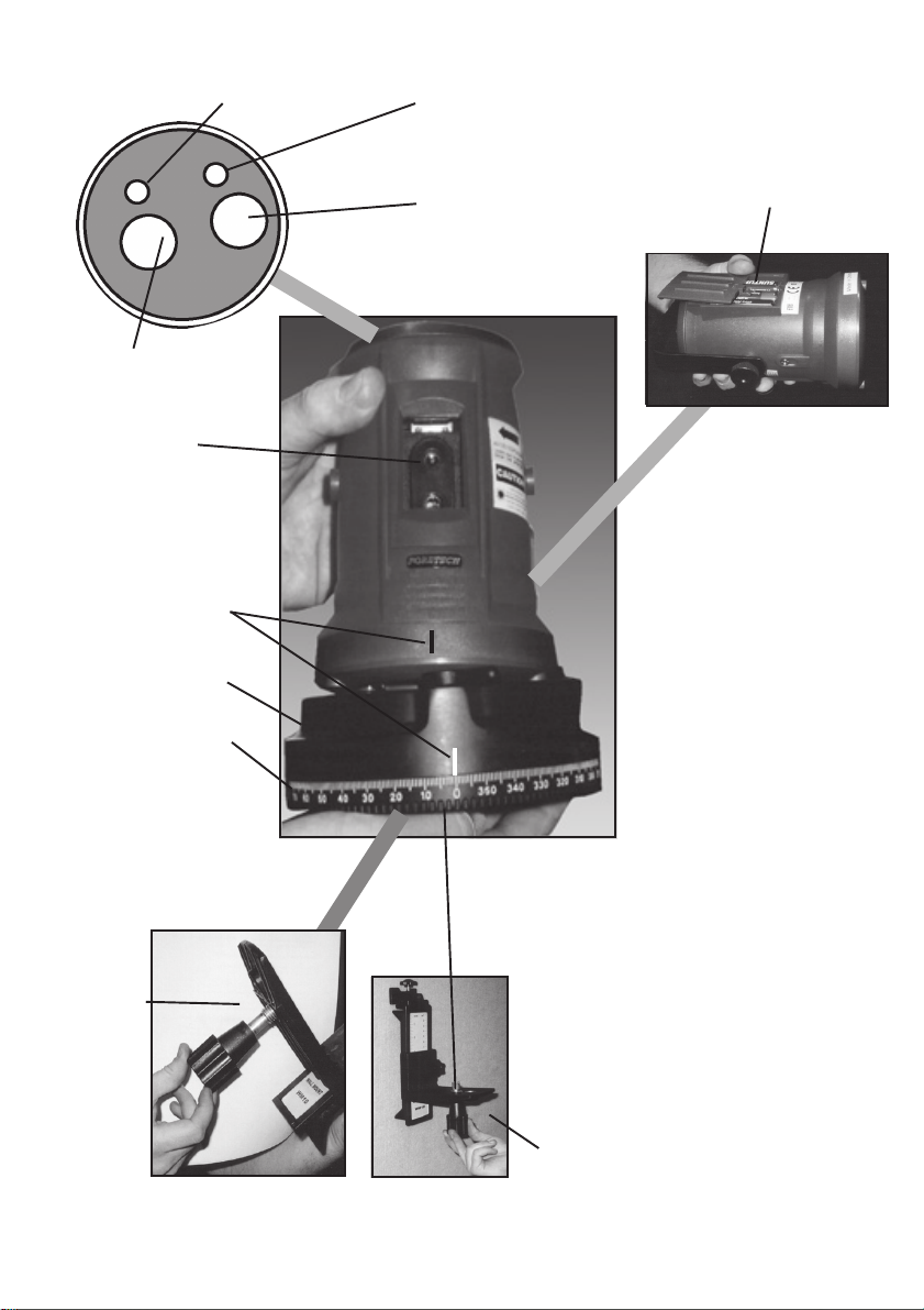
Identification of Parts
Indicator Light
Ve rtical Plane
Indicator Light
IV
Vertical Plane
On/Off Switch
Laser Output
Window
Center Line
Locking Wheel
3600 Rotary Base
H
TOP
Horizontal Plane
On/Off Switch
Battery Compartment
3 “AA” Batteries (2)
BACK
BOTTOM
5/8” Mounting
Thread for
Wall Mount (1)
Wall Mount
(1)
Figure A
SKU 91179 For technical questions, please call 1-800-444-3353. Page 4
Page 5

Features
• Independent laser diodes emit clear and precise red laser lines
• Magnetic damping compensator stabilizes quickly
• Alarm sounds when out of leveling range
• Use horizontal (level) and vertical (plumb) lines together, or separately
• Broad +/-5
0 self-leveling range
• Bearing pendulum compensator offers strong rigidity
• Pendulum lock protects the internal structure during transportation and
storage
• Unit includes various accessories
.:maebleveL80ta"'33
ycaruccA
htgneLeniL
elgnAnaF
egnaRgnikroW
ecruoSresaL
egnaRgnilevel-fleS
deepSgnilevel-fleS
emiTgnitarepO
rewoP
eziS
thgieW
trelAlevel-fo-tuO
kcoLmuludneP
.xorppA'64ta'33ecnatsidtegrat
°07.xorppA
otpU'5.56aeragnikrowfonoitanimullinoputnedneped,
5±°
sdnoces6<
5.3XretemaiD"thgieH"9.5
.sbL345.1
ni-tliuB
ni-tliuB
±)dneotdne(enalplatnoziroHmm2ta'61htgnelenil
±)dneotdne(enalplacitreVm3tam'61htgnelenil
sedoidresaletarapesowT
esusuounitnocfosruoh42
seirettaBenilaklA”AA“X3
REV 03/05
SKU 91179 For technical questions, please call 1-800-444-3353. Page 5
Page 6

Unpacking
When unpacking, check to make sure the parts shown on the cover of this
manual are included. If any parts are missing or broken, please call Harbor
Freight Tools at the number on the cover of this manual.
Operating Instructions
A Tripod may also be used with the Cross Line Laser (not included).
1. After removing the Laser from the Carrying Bag (4), insert the three “AA”
Batteries (2) into the battery compartment according to the polarity symbols
shown in the Battery Compartment. Close the Battery Compartment door.
See Figure A.
2. Release the Pendulum Lock on the bottom of the Laser, by sliding the “door”
to the center.
3. Be sure to set the Laser on as flat a surface as possible. The self-leveling
range of the Laser is within ±5°. The Laser will work properly if it is
positioned within its self-leveling range.
See Figure B.
Figure A
(2)
3 “AA” Batteries
Pendulum
Lock “door”
(bottom of Laser)
Figure B
4. Press the button on the top of the unit to switch “ON”. Either button will turn
on the red indicator light. The “H” Button is for the horizontal line and the “IV”
button is for the vertical line.
Indicator
Light
Vertical
Light
See Figure C.
H
IV
Horizontal Light
Figure C
5. For safety reasons, after you have pushed either horizontal or vertical
buttons to switch “ON”, there will be a delay of one second before the Laser
beam is emitted. This delay will not happen when pressing the second
button. If the Laser Beam blinks, it means it is still locked or NOT within the
leveling range.
6. Allow 4-6 seconds for the horizontal and vertical Laser lines to be stabilized.
After stabilization, the Laser lines can be used for measurement reference.
Laser lines may swing slightly due to vibration from surroundings.
SKU 91179 For technical questions, please call 1-800-444-3353. Page 6
Page 7

How to Use the Rotary Base:
1. Loosen the Hand Wheel and put the Laser unit on the Rotary Base. Adjust
so that the “center line” under the Laser Window is aligned with the “center
line” of the Rotary Base. Tighten the Hand Wheel. Recognize the rotating
range according to the graduation aiming at the “center line.”
See Figures D & E.
Center Line
on Laser
and Center
Line on
Rotary Base
Figure D
Laser
Window
Hand Wheel
Figure E
Center
Lines
2. Rotating Base has a 3600 scale. Set at desired increments for measuring,
i.e. tiles for flooring, cabinet installation, wainscoting and wallpapering,
bathroom tiling, putting up pictures, aligning shelves, window framing, etc.
See Figure E.
To Use the Wall Mount:
1. Fix the Wall Mount (1) to the wall with screws (not included). Be sure the
holes drilled for the mounting of the screws are level and that the wall is solid
and there are no hidden electrical wires that may interfere. Leave the screws
extended from the wall by about 1/4” so you can slip the Wall Mount (1) on
and off the wall. Use the Adjustment Knob to choose measurements.
Figure G.
You can also use the Magnetic Bracket (3) (not shown) for hanging
from a steel beam or shelf.
2. Set the Hand Wheel, Rotary Base and Laser (assembled) on the shelf of the
Wall Mount (1). Use the Mounting Knob for the Wall Mount (1) and thread it
through the shelf and into the threaded hole on the bottom of the Laser/
Rotary Base assembly. Adjust laser level to proper height. Lock it in place
with the Holding Knob on the side of the Wall Bracket.
See Figure F, G & H.
See
Mounting
Knob
Figure F
Figure G
Holding
Knob
Wall Mount
Shelf
Figure H
SKU 91179 For technical questions, please call 1-800-444-3353. Page 7
Page 8

Level Beam Accuracy:
1. Set up the instrument with the Wall Mount (1) or Tripod (not included),
centered between two walls approximately 16 ft. apart . Please ensure the
Rotary Base is approximately on level.
2. Press both the horizontal and vertical buttons to project a laser cross on wall
A. Mark point a1 at the intersection of the beams. Turn the cross line laser
180° and repeat on wall B, marking point b1 at the intersection of the beams.
See Figure I.
3. Move the instrument to the point 2 ft. from wall A and repeat step 21 marking
the intersections as a2 and b2.
4. Measuring the distance between a1 and a2 as Ia1 -a
a1-a
2
I
2
I-I
.
b1 -b
II
<1mm, the accuracy is within tolerance. Otherwise, return
2
as Ib1 -b
5. If
II
the instrument to a qualified technician for repair.
Figure I
I
, and b1, and b
2
2
Horizontal Beam Level Accuracy (End to End)
1. Set up the instrument with the Wall Mount (1) or Tripod (not included),
approximately 16 ft. from the wall. Please ensure the Rotary Base in
approximately level.
2. Press both the horizontal and vertical buttons to project a laser cross on the
wall, mark point M1 8 ft. from the intersection of the beams on the horizontal
beam.
See Figure J.
3. Turn the instrument until the vertical beam has moved 16.4 ft. to the right
side, and mark M2 8 ft. from the intersection of the beams on the horizontal
line.
4. Measure the distance between M1 and M2.
5. If the distance is less or equal to
2mm, the accuracy is within
tolerance. Otherwise, take the
instrument to a qualified
technician for repair.
SKU 91179 For technical questions, please call 1-800-444-3353. Page 8
See Figure J.
8 ft.
M1
8 ft.
M2
16 ft.
Figure J
REV 03/05
Page 9

Vertical Beam Level Accuracy (End to End)
1. Set up the instrument with the Wall Mount (1) or Tripod (not included),
approximately 16 ft. from the wall. (The wall should be at least 16-1/2 ft.
high). Please ensure the Rotary Base is approximately level.
2. Press both the horizontal and vertical buttons to project a laser cross on the
wall, mark point A 8 ft. above the intersection of the beams on the vertical
beam.
3. Regarding A as a starting point and nail one end of a str ing with plumb bob
(not included) on A. The length of the string should be over 16 ft..
4. Mark M1 8 ft. from point A on the string.
5. Mark M2 8 ft. above the intersection of the beams on the vertical line.
6. Measure the distance between M1 and M2.
7. If the distance is less or equal to 10 ft., the accuracy is within tolerance.
Otherwise, take the instrument to a qualified technician for repair.
After Using Laser
1. Detach Laser from Wall Mount (1) or Tripod (not included).
2. Switch off both laser lines, horizontal and vertical. Check to see indicator
light is off.
3. Lock Pendulum Lock by sliding the door from the center position. After use
the Pendulum Lock should be locked before the instrument is put away in the
Carrying Bag (4).
Note: When the Pendulum Lock is unlocked, do not shake or strike the
instrument, otherwise the mechanism inside could be damaged.
Warning: Always make certain the Laser is OFF before adjusting or changing batteries.
To change the batteries, remove the Battery Cover, (see figure A), and insert
three new “AA” Batter ies. Follow the polarity symbols so that the positive and
negative ends of the batteries match the diagram. Do not mix old and new
batteries. Remove batter ies when stor ing Laser.
Warning: This product contains or produces a chemical known to the State of
California to cause cancer and birth defects (or other reproductive harm). (California Health & Safety Code § 25249.5,
SKU 91179 For technical questions, please call 1-800-444-3353. Page 9
See Figure B.
et seq.
)
Page 10

Swing Mechanism Assembly
Swing Mechanism Parts List
SKU 91179 For technical questions, please call 1-800-444-3353. Page 10
Page 11

Body Parts Assembly
Laser Body Parts List
SKU 91179 For technical questions, please call 1-800-444-3353. Page 11
Page 12

Magnetic Damping
Device Assembly
Magnetic Damping
Parts List
SKU 91179 For technical questions, please call 1-800-444-3353. Page 12
Page 13

Rotary Base Assembly
Rotary Base Assembly
Parts List
SKU 91179 For technical questions, please call 1-800-444-3353. Page 13
Page 14

Additional Parts List
PART # DESCRIPTION QTY
Part 4
See Page 6
Part 5
2
3
4
5
1
Wall Mount
Double “AA” Batteries (not shown below)
Magnetic Bracket
Carrying Bag
Laser Enhancement Glasses
3600 Rotary Base
See Pages 7 & 8
Maintenance
1
3
1
1
1
Part 1
Mounting
Knob
Part 3
Clean with a soft, dry cloth. Do not use solvents or chemicals to clean Cross Line Laser output
window. Keep out of harsh, rainy conditions. Do not use a dryer or fire to dry this instrument.
Always put the Cross Line Laser into the Carrying Bag (4) when not in use. This is a precise and
delicate instrument. Handle with care
PLEASE READ THE FOLLOWING CAREFULLY
THE MANUFACTURER AND/OR DISTRIBUTOR HAS PROVIDED THE PARTS DIAGRAM IN THIS
MANUAL AS A REFERENCE TOOL ONLY. NEITHER THE MANUFACTURER NOR DISTRIBUTOR
MAKES ANY REPRESENTATION OR WARRANTY OF ANY KIND TO THE BUYER THAT HE OR SHE
IS QUALIFIED TO MAKE ANY REPAIRS TO THE PRODUCT OR THAT HE OR SHE IS QUALIFIED TO
REPLACE ANY PARTS OF THE PRODUCT. IN FACT, THE MANUFACTURER AND/OR DISTRIBUTOR
EXPRESSLY STATES THAT ALL REPAIRS AND PARTS REPLACEMENTS SHOULD BE UNDERTAKEN
BY CERTIFIED AND LICENSED TECHNICIANS AND NOT BY THE BUYER. THE BUYER ASSUMES
ALL RISK AND LIABILITY ARISING OUT OF HIS OR HER REPAIRS TO THE ORIGINAL PRODUCT
OR REPLACEMENT PARTS THERETO, OR ARISING OUT OF HIS OR HER INSTALLATION OF
REPLACEMENT PARTS THERETO.
NOTE: Some parts are listed and shown for illustration purposes only and are not available individually as
replacement parts.
SKU 91179 For technical questions, please call 1-800-444-3353. Page 14
 Loading...