

Page 1
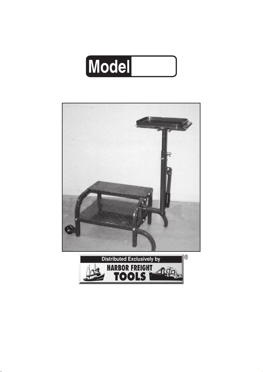
2-STEP WORK ST AND WITH
TOOL TRA Y
91174
ASSEMBLY INSTR UCTIONS
3491 Mission Oaks Blvd., Camarillo, CA 93011
Visit our Web site at http://www.harborfreight.com
®
Copyright© 2004 by Harbor Freight Tools
of this manual or any artwork contained herein may be reproduced in any
shape or form without the express written consent of Harbor Freight Tools.
For technical questions and replacement parts, please call 1-800-444-3353
.
All rights reserved. No portion
Page 2

Specifications
Maximum Weight Capacity Steps: 350 Lbs.; Tray: 50 Lbs.
Tool Tray Lift Range 31-1/2” to 51-3/16”
Tool Tray Size 12” x 11-3/4” x 1” with 15 Holes (various sizes)
Step Sizes Lower: 15” x 19-11/16”; Upper: 7-7/8” x 19-11/16”
Steel Finish Red Enamel
Overall W eight 40 Lbs.
Save This Manual
You will need the manual for the safety warnings and precautions, assembly
instructions, parts list and diagram. Keep your invoice with this manual. Write the
invoice number on the inside of the front cover. Keep the manual and invoice in a
safe and dry place for future reference.
Safety Warnings and Precautions
WARNING: When using tool, basic safety precautions should always be followed to reduce the risk of personal injury and damage to equipment.
Read all instructions before using this product!
1. Keep work area clean. Cluttered areas invite injuries.
2. Keep children away. Children must never be allowed in the work area. Do
not let children play with this product.
3. Store idle equipment. When not in use, this product must be stored in a dry
location to inhibit rust. Always lock up tools and keep out of reach of children.
4. Dress properly. Do not wear loose clothing or jewelry as they can be caught
in moving parts. Protective, electrically nonconductive clothes and nonskid
footwear are recommended when working. Wear restrictive hair covering to
contain long hair.
5. Use eye and ear protection. Always wear ANSI approved impact safety
goggles when working around tools.
6. Do not overreach. Keep proper footing and balance at all times.
7. Use the right tool for the job. Do not attempt to force a small stand to carry
the same weight as a larger stand. There are certain applications for which this
product was designed. Do not modify this product and do not use this product
for a purpose for which it was not intended.
8. Stay alert. Watch what you are doing, use common sense. Do not assemble
this product when you are tired.
9. Check for damaged parts. Before using any tool, any part that appears
damaged should be carefully checked to determine that it will operate properly
and perform its intended function. Check for loose parts and any other condition
that may affect the operation of this product. Replace loose or worn parts
immediately . Any part that is damaged should be properly repaired or replaced
by a qualified technician.
SKU 91174 Page 2
Page 3

10. Replacement parts. When servicing, use only identical replacement par ts.
Use of any other parts will void the warranty.
11. Do not operate this product if under the influence of alcohol or drugs.
Read warning labels on prescriptions to determine if your judgment or reflexes
are impaired while taking drugs. If there is an y doubt, do not stand upon or try
to assemble this product.
12. Do not exceed the Maximum Weight capacity for either the Steps or the
Tray, mentioned in the
Specifications
table on page 2.
Caution: Be aware of d ynamic loading!
Jumping or bouncing on the Stand may create f or a brief instant, an excess
load, which may result in damage to the product and/or personal injury.
Warning: The warnings, cautions, and instructions discussed in this instruction
manual cannot cover all possible conditions and situations that may occur .
It must be understood by the operator that common sense and caution
are factors which cannot be built into this product, but must be supplied
by the operator.
Unpacking
When unpacking, check to make sure the f ollowing parts are included.
If any parts are missing or broken, please call Harbor Freight Tools at the
number on the cover of this manual.
Assembly Instructions
Note: Assemble on a smooth surface to avoid scratching.
2. Select the Right Leg (4) and Left Leg (7). Attach the Lo wer Step (5) to the Legs
(4 & 7) (the mounting hole for the P ost (3) must be on the Right Leg’s (4) side-
see Figure A
Washers (17), Washers (16) and Nuts (15). Finger tighten.
) by matching up the holes and securing with Bolts (14), Lock
3. Attach the Upper Step (6) as in step #2. Tighten all hardware.
Bolt (14)
Lock Washer (17)
Washer (16)
Nut (15)
This hole must be
here-see Step 2.
Lock Washer (17)
Lower Step (5)
Right Leg (4)
Figure A
SKU 91174 Page 3
See Figure A
Upper Step
(6)
Bolt (14)
Washer (16)
Nut (15)
Left Leg (7)
.
Page 4

4. Fit the Wheel (8) on the outside of the Left Leg (7) inside the bracket. Position
the Bolt (12) through the bracket on Leg (7), the Wheel (8), and the other side
of the bracket. Tighten with the Nylon Nut (18) on the inside of the Work Stand.
Repeat on the other side of the Leg (7).
Left Leg (7)
with brackets
Wheel (8)
Bolt (12)
Nylon Nut (18)
Figure B
See Figure B.
5. The Post (3) is mounted on the Right Leg (4) with Bolts (12) in the two upper
holes in the Post plate. The Bolt (13) goes in the lower hole. Attach all with
Washers (16), Lock Washers (17) and Nuts (15).
Tray (1)
See Figure C .
Post (3)
Post
Plate (3)
Bolt (12)
Washer (16)
Lock Washer (17)
Nut (15)
Figure C
Wing
Bolt
(11)
Hand
Grip
(9)
Bolt (13)
Washer (16)
Lock Washer (17)
Nut (15)
Pin
Tool Tray (1)
Figure D
Bolts (10,
Washers (16)
Lock
Washers (17)
Extention
Tube (2)
Wing Bolt (11)
6. The Tool Tray (1) needs to be connected to the Extension Tube (2). Use Bolts
(10), Washers (16), and Lock Washers (17) to attach the Tray and tighten all
hardware.
See Figure D.
Once the Tool Tray (1) is connected to the Extension
T ube (2), the Tube can be slipped into the Post (3). Choose the height y ou want
the Tool Tray at, line up the hole in the Extension T ube (2) to the hole in the P ost
(3), tighten the Wing Nut (11), and use the Pin on the P ost (3) to lock in position.
See Figures C & D.
Note: Do not place any weight on the Tool Tray (1) unless the Pin is in place.
7. Place Rubber Stoppers (not shown) on the end of each leg.
8. The Handle (9) is used for transporting the W ork Station with Tool Tray. Do not
have any objects on the Tray when moving it from one area to another.
SKU 91174 Page 4
Page 5

Parts List
Part # Description Qty.
1
2
3
4
5
6
7
8
9
Tool Tray
Extension Tube
Post
Right Leg
Lower Step
Upper Step
Left Leg
3” Wheel
Hand Grip
1
1
1
1
1
1
1
2
1
Assembly Drawing
12
8
18
15
16
17
14
12
18
15
14
7
8
5
17
16
14
17
Part # Description Qty.
16
17
4
Tray Bolt
Wing Bolt
Bolt
Bolt
Step Bolt
Nut
Washer
Lock Washer
Nylon Nut
1
15
14
2
14
16
10
11
12
13
14
15
16
17
18
14
6
15
12
4
1
4
1
6
8
12
12
2
17
16
10
3
11
9
12
13
PLEASE READ THE FOLLOWING CAREFULLY
THE MANUFACTURER AND/OR DISTRIBUTOR HAS PROVIDED THE PARTS DIAGRAM IN THIS
MANUAL AS A REFERENCE TOOL ONLY. NEITHER THE MANUFACTURER NOR DISTRIBUTOR
MAKES ANY REPRESENTATION OR WARRANTY OF ANY KIND TO THE BUYER THAT HE OR SHE IS
QUALIFIED TO MAKE ANY REPAIRS TO THE PRODUCT OR THAT HE OR SHE IS QUALIFIED TO
REPLACE ANY PARTS OF THE PRODUCT. IN FACT, THE MANUFACTURER AND/OR DISTRIBUTOR
EXPRESSLY STATES THat ALL REPAIRS AND PARTS REPLACEMENTS SHOULD BE UNDERTAKEN
BY CERTIFIED AND LICENSED TECHNICIANS AND NOT BY THE BUYER. THE BUYER ASSUMES
ALL RISK AND LIABILITY ARISING OUT OF HIS OR HER REPAIRS TO THE ORIGINAL PRODUCT OR
REPLACEMENT PARTS THERETO, OR ARISING OUT OF HIS OR HER INSTALLATION OF REPLACEMENT PARTS THERETO.
NOTE: Some parts are listed and shown for illustration purposes only and are not available individually as replacement parts.
SKU 91174 Page 5
 Loading...