

Page 1
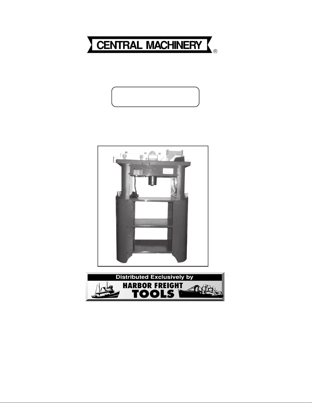
ROUTER WITH FULL SIZE TABLE
®
Model 91130
ASSEMBLY AND OPERATING INSTRUCTIONS
3491 Mission Oaks Blvd., Camarillo, CA 93011
Visit our Web site at: http://www.harborfreight.com
Copyright© 2004 by Harbor Freight Tools®. All rights reserved. No portion of this
manual or any artwork contained herein may be reproduced in any shape or form
without the express written consent of Harbor Freight Tools.
For technical questions or replacement parts, please call 1-800-444-3353.
Page 2
PRODUCT SPECIFICATIONS
Item Description
Electrical Requirements 120V / 60 Hz / 750 Watts / 4.3 Load Amps
1 HP Motor / 8,400-27,800 RPM Variable Speed
3- Prong, Grounded, Power Plug
Table Dimensions 27” Wide x 18” Deep x 1-1/2” Thick
Table Height 38”
Overall Height 43-1/2”
Cutting Depth 1-27/64”
Collet Capacity 1/4” And 1/2”
Accessories 1/4” Collet / 1/2” Collet / Miter Gauge
Guide Fence / Feather Board / Wrench
Dust Collector Port
Weight 75.6 Pounds
UNPACKING
When unpacking, check to make sure all the parts shown on the Parts Lists on pages 26
and 27 are included. If any parts are missing or broken, please call Harbor Freight Tools
at the number shown on the cover of this manual as soon as possible.
SAVE THIS MANUAL
You will need this manual for the safety warnings and precautions, assembly, operating,
inspection, maintenance and cleaning procedures, parts list and assembly diagram.
Keep your invoice with this manual. Write the invoice number on the inside of the front
cover. Keep this manual and invoice in a safe and dry place for future reference.
GENERAL SAFETY RULES
WARNING!
READ AND UNDERSTAND ALL INSTRUCTIONS
Failure to follow all instructions listed below may result in
electric shock, fire, and/or serious injury.
SAVE THESE INSTRUCTIONS
WORK AREA
1. Keep your work area clean and well lit. Cluttered benches and dark areas
invite accidents.
2. Do not operate power tools in explosive atmospheres, such as in the pres-
ence of flammable liquids, gases, or dust. Power tools create sparks which
may ignite the dust or fumes.
REV 08/04
SKU 91130 For technical questions, please call 1-800-444-3353. Page 2
Page 3

3. Keep bystanders, children, and visitors away while operating a power tool.
Distractions can cause you to lose control. Protect others in the work area from
debris such as chips and sparks. Provide barriers or shields as needed.
ELECTRICAL SAFETY
4. Grounded tools must be plugged into an outlet properly installed and
grounded in accordance with all codes and ordinances. Never remove the
grounding prong or modify the plug in any way. Do not use any adapter
plugs. Check with a qualified electrician if you are in doubt as to whether
the outlet is properly grounded. If the tools should electrically malfunction or
break down, grounding provides a low resistance path to carry electricity away
from the user.
5. Double insulated tools are equipped with a polarized plug (one blade is
wider than the other). This plug will fit in a polarized outlet only one way. If
the plug does not fit fully in the outlet, reverse the plug. If it still does not
fit, contact a qualified electrician to install a polarized outlet. Do not
change the plug in any way. Double insulation eliminates the need for the
three wire grounded power cord and grounded power supply system.
6. Avoid body contact with grounded surfaces such as pipes, radiators,
ranges, and refrigerators. There is an increased risk of electric shock if your
body is grounded.
7. Do not expose power tools to rain or wet conditions. Water entering a power
tool will increase the risk of electric shock.
8. Do not abuse the Power Cord. Never use the Power Cord to carry the tools
or pull the Plug from an outlet. Keep the Power Cord away from heat, oil,
sharp edges, or moving parts. Replace damaged Power Cords immediately. Damaged Power Cords increase the risk of electric shock.
9. When operating a power tool outside, use an outdoor extension cord
marked “W-A” or “W”. These extension cords are rated for outdoor use, and
reduce the risk of electric shock.
PERSONAL SAFETY
10. Stay alert. Watch what you are doing, and use common sense when operating a power tool. Do not use a power tool while tired or under the influence of drugs, alcohol, or medication. A moment of inattention while operat-
ing power tools may result in serious personal injury.
SKU 91130 For technical questions, please call 1-800-444-3353. Page 3
Page 4

11. Dress properly. Do not wear loose clothing or jewelry. Contain long hair.
Keep your hair, clothing, and gloves away from moving parts. Loose
clothes, jewelry, or long hair can be caught in moving parts.
12. Avoid accidental starting. Be sure the Power Switch is off before plugging
in. Carrying power tools with your finger on the Power Switch, or plugging in
power tools with the Power Switch on, invites accidents.
13. Remove adjusting keys or wrenches before turning the power tool on. A
wrench or a key that is left attached to a rotating part of the power tool may result
in personal injury.
14. Do not overreach. Keep proper footing and balance at all times. Proper
footing and balance enables better control of the power tool in unexpected
situations.
15. Use safety equipment. Always wear eye protection. Dust mask, non-skid
safety shoes, hard hat, or hearing protection must be used for appropriate
conditions.
TOOL USE AND CARE
16. Use clamps (not included) or other practical ways to secure and support
the workpiece to a stable platform. Holding the work by hand or against your
body is unstable and may lead to loss of control.
17. Do not force the tool. Use the correct tool for your application. The correct
tool will do the job better and safer at the rate for which it is designed.
18. Do not use the power tool if the Power Switch does not turn it on or off.
Any tool that cannot be controlled with the Power Switch is dangerous and must
be replaced.
19. Disconnect the Power Cord Plug from the power source before making any
adjustments, changing accessories, or storing the tool. Such preventive
safety measures reduce the risk of starting the tool accidentally.
20. Store idle tools out of reach of children and other untrained persons. Tools
are dangerous in the hands of untrained users.
21. Maintain tools with care. Keep cutting tools sharp and clean. Properly
maintained tools with a sharp cutting edge are less likely to bind and are easier
to control. Do not use a damaged tool. Tag damaged tools “Do not use” until
repaired.
SKU 91130 For technical questions, please call 1-800-444-3353. Page 4
Page 5

22. Check for misalignment or binding of moving parts, breakage of parts, and
any other condition that may affect the tool’s operation. If damaged, have
the tool serviced before using. Many accidents are caused by poorly main-
tained tools.
23. Use only accessories that are recommended by the manufacturer for your
model. Accessories that may be suitable for one tool may become hazardous
when used on another tool.
SERVICE
24. Tool service must be performed only by qualified repair personnel. Service
or maintenance performed by unqualified personnel could result in a risk of injury.
25. When servicing a tool, use only identical replacement parts. Follow
instructions in the
manual. Use of unauthorized parts or failure to follow maintenance instructions
may create a risk of electric shock or injury.
“Inspection, Maintenance, And Cleaning”
section of this
SPECIFIC SAFETY RULES
1. Maintain a safe working environment. Keep the work area well lit. Make sure
there is adequate surrounding workspace. Always keep the work area free of
obstructions, grease, oil, trash, and other debris. Do not use the Router Table in
areas near flammable chemicals, dusts, and vapors. Do not use this product in a
damp or wet location.
2. Maintain labels and nameplates on the Router. These carry important
information. If unreadable or missing, contact Harbor Freight Tools for a replacement.
3. Do not force the equipment. This Router will do the work better and safer at
the speed and capacity for which it was designed.
4. Keep all guards in place and in working order.
5. Remove all adjusting wrenches from the Router before turning it on.
6. Do not abuse the Power Cord. Do not use the Power Cord to pull its Plug from
an electrical outlet. Keep the Power Cord away from heat, oil, sharp edges, and
moving parts. Route the Power Cord safely. Protect the Power Cord from being
damaged by other equipment in the work area. Do not route the Power Cord
where it can be walked on or tripped over. Replace a damaged Power Cord
immediately.
SKU 91130 For technical questions, please call 1-800-444-3353. Page 5
Page 6

7. Make sure the Power Switch is in the “OFF” position before plugging in the
Power Cord.
8. Do not use this Router for cutting metals or brittle materials. Do not cut
dangerous materials, such as asbestos which can cause harmful dust or vapors.
9. Before using the Router, make sure the router bit (not included) is properly
mounted. Make sure the router bit is not bent or cracked.
10. Allow the router bit to spin up to full speed before feeding wood into it.
When turning off the Router, allow the router bit to spin down and stop on its
own. Do not press against the router bit to stop it.
11. Do not force the material into the router bit when cutting. Apply moderate
pressure, allowing the router bit to cut without being forced.
12. Never attempt to remove material stuck in the moving parts of the Router
while the machine is plugged in and running.
13. Whenever possible, use safe, practical ways to hold and support the
workpiece.
14. Turn off the Router if the material is to be backed out of an uncompleted
cut.
15. Avoid serious personal injury. Always keep hands and fingers away from
the spinning router bit.
16. Store idle equipment. When not in use, tools and equipment should be
stored in a dry location to inhibit rust. Always lock up tools and equipment,
and keep out of reach of children.
17. Use eye, hearing, and breathing protection. Always wear ANSI approved
safety impact eye goggles, hearing protectors, and dust masks or respirator
when working with the Router Table.
18. Do not use this product if under the influence of alcohol or drugs. Read
warning labels on prescriptions to determine if your judgement or reflexes are
impaired while taking drugs. If there is any doubt, do not attempt to use this
product.
19. Industrial applications must follow OSHA requirements.
20. Never leave the Router running unattended. Turn off the power, and do not
leave the machine until it comes to a complete stop.
SKU 91130 For technical questions, please call 1-800-444-3353. Page 6
Page 7

21. Maintain this product with care. Keep the Router clean and dry for better and
safer performance. Make sure to keep router bits sharp and clean. For your
safety, service and maintenance should be performed regularly by a qualified
technician.
22. Use the right tool or attachment for the right job. Do not attempt to force a
small tool or attachment to do the work of a larger industrial tool or attachment.
There are certain applications for which this product was designed. It will do the
job better and more safely at the rate for which it was intended. Do not modify
this product, and do not use this product for a purpose for which it was not intended.
23. Always keep children away from the Router. All visitors should be kept a safe
distance away from the machine. Make the workshop “kid proof” with padlocks,
master switches, or by removing the starter keys.
24. Never stand on the Router Table. Serious personal injury can result if the
machine is tipped or if the router bit is unintentionally contacted.
25. Make sure to feed the workpiece into the router bit and against the rotation
of the router bit.
26. Always turn off the Router and unplug the Power Cord from its electrical
outlet before changing accessories or performing any inspection, maintenance, or cleaning procedures.
27. WARNING! Some dust created by power sanding, sawing, grinding, drill-
ing, and other construction activities, contain chemicals known (to the State of
California) to cause cancer, birth defects or other reproductive harm. Some
examples of these chemicals are: lead from lead-based paints, crystalline silica
from bricks and cement or other masonry products, arsenic and chromium from
chemically treated lumber. Your risk from these exposures varies, depending on
how often you do this type of work. To reduce your exposure to these chemicals:
work in a well ventilated area, and work with approved safety equipment, such as
those dust masks that are specially designed to filter out microscopic particles.
(California Health & Safety Code 25249.5, et seq.)
28. WARNING! People with pacemakers should consult their physician(s)
before using this product. Electromagnetic fields in close proximity to a heart
pacemaker could cause interference to or failure of the pacemaker.
29. WARNING! The warnings, precautions, and instructions discussed in this
manual cannot cover all possible conditions and situations that may occur. The
operator must understand that common sense and caution are factors which
cannot be built into this product, but must be supplied by the operator.
SKU 91130 For technical questions, please call 1-800-444-3353. Page 7
Page 8
GROUNDING
WARNING!
Improperly connecting the grounding wire can result in the risk of electric
shock. Check with a qualified electrician if you are in doubt as to whether the
outlet is properly grounded. Do not modify the power cord plug provided with
the tool. Never remove the grounding prong from the plug. Do not use the
tool if the power cord or plug is damaged. If damaged, have it repaired by
a service facility before use. If the plug will not fit the outlet, have a proper
outlet installed by a qualified electrician.
GROUNDED TOOLS: TOOLS WITH THREE PRONG PLUGS
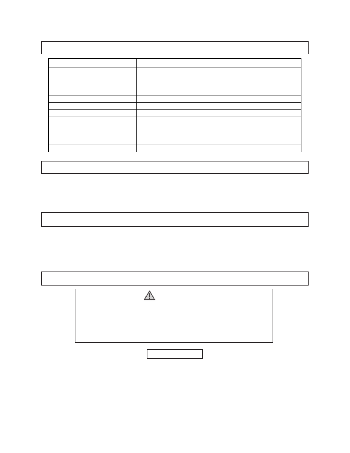
1. Tools marked with “Grounding Required” have a three wire cord and three prong
grounding plug. The plug must be connected to a properly grounded outlet. If
the tool should electrically malfunction or break down, grounding provides a low
resistance path to carry electricity away from the user, reducing the risk of electric shock. (See Figure A.)
2. The grounding prong in the plug is connected through the green wire inside the
cord to the grounding system in the tool. The green wire in the cord must be the
only wire connected to the tool’s grounding system and must never be attached
to an electrically “live” terminal. (See Figure A.)
3. Your tool must be plugged into an appropriate outlet, properly installed and
grounded in accordance with all codes and ordinances. The plug and outlet
should look like those in the following illustration. (See Figure A.)
FIGURE A
SKU 91130 For technical questions, please call 1-800-444-3353. Page 8
Page 9
DOUBLE INSULATED TOOLS: TOOLS WITH TWO PRONG PLUGS
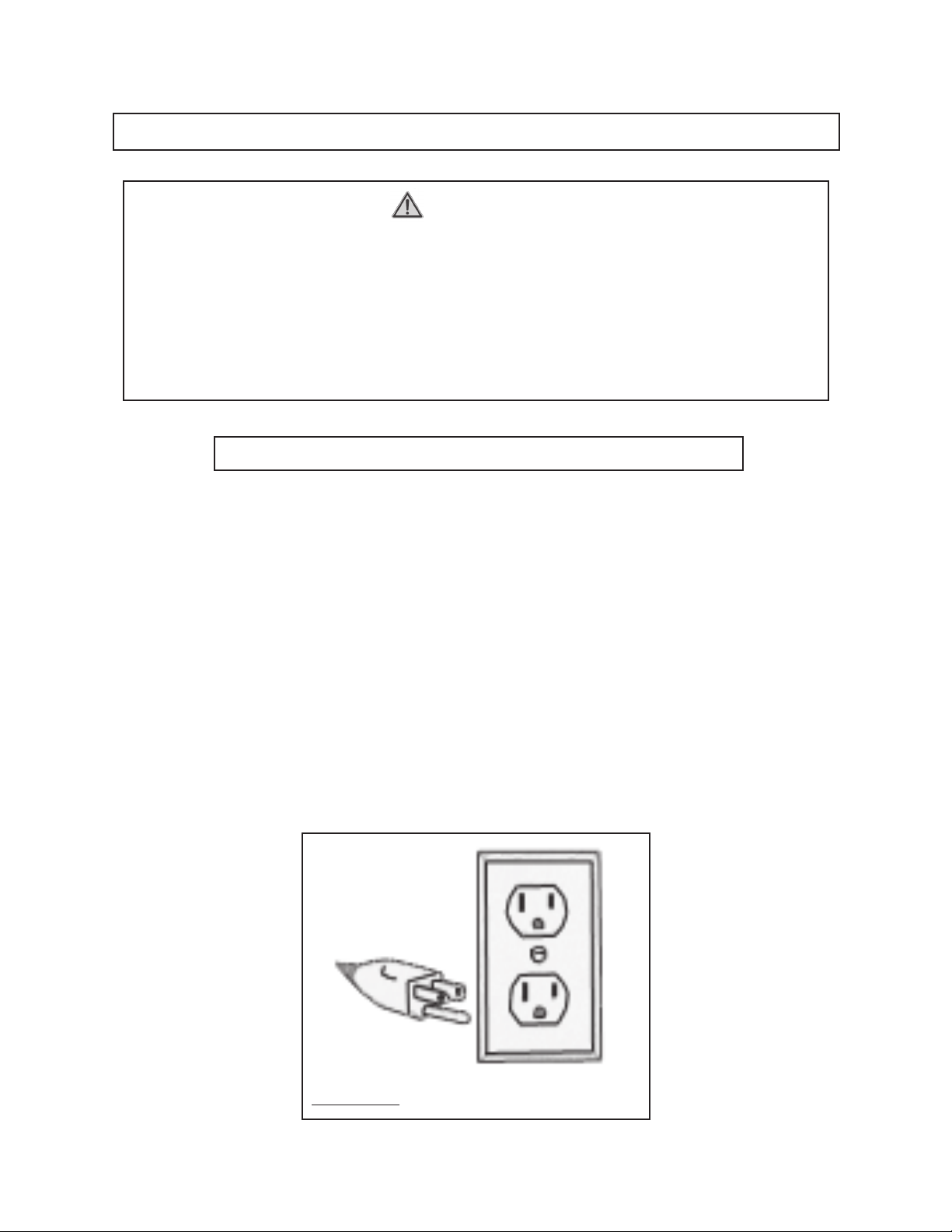
4. Tools marked “Double Insulated” do not require grounding. They have a special
double insulation system which satisfies OSHA requirements and complies with
the applicable standards of Underwriters Laboratories, Inc., the Canadian
Standard Association, and the National Electrical Code. (See Figure B.)
5. Double insulated tools may be used in either of the 120 volt outlets shown in the
following illustration. (See Figure B.)
FIGURE B
EXTENSION CORDS
1.
2. As the distance from the supply outlet increases, you must use a heavier gauge
3. The smaller the gauge number of the wire, the greater the capacity of the cord.
4. When using more than one extension cord to make up the total length, make
Grounded
can use either a two or three wire extension cord.
extension cord. Using extension cords with inadequately sized wire causes a
serious drop in voltage, resulting in loss of power and possible tool damage.
(See Figure C, next page.)
For example, a 14 gauge cord can carry a higher current than a 16 gauge cord.
(See Figure C.)
sure each cord contains at least the minimum wire size required.
(See Figure C.)
tools require a three wire extension cord.
Double Insulated
tools
5. If you are using one extension cord for more than one tool, add the nameplate
amperes and use the sum to determine the required minimum cord size.
(See Figure C.)
SKU 91130 For technical questions, please call 1-800-444-3353. Page 9
Page 10
6. If you are using an extension cord outdoors, make sure it is marked with the
(
)
suffix “W-A” (“W” in Canada) to indicate it is acceptable for outdoor use.
7. Make sure your extension cord is properly wired and in good electrical condition.
Always replace a damaged extension cord or have it repaired by a qualified
electrician before using it.
8. Protect your extension cords from sharp objects, excessive heat, and damp or
wet areas.
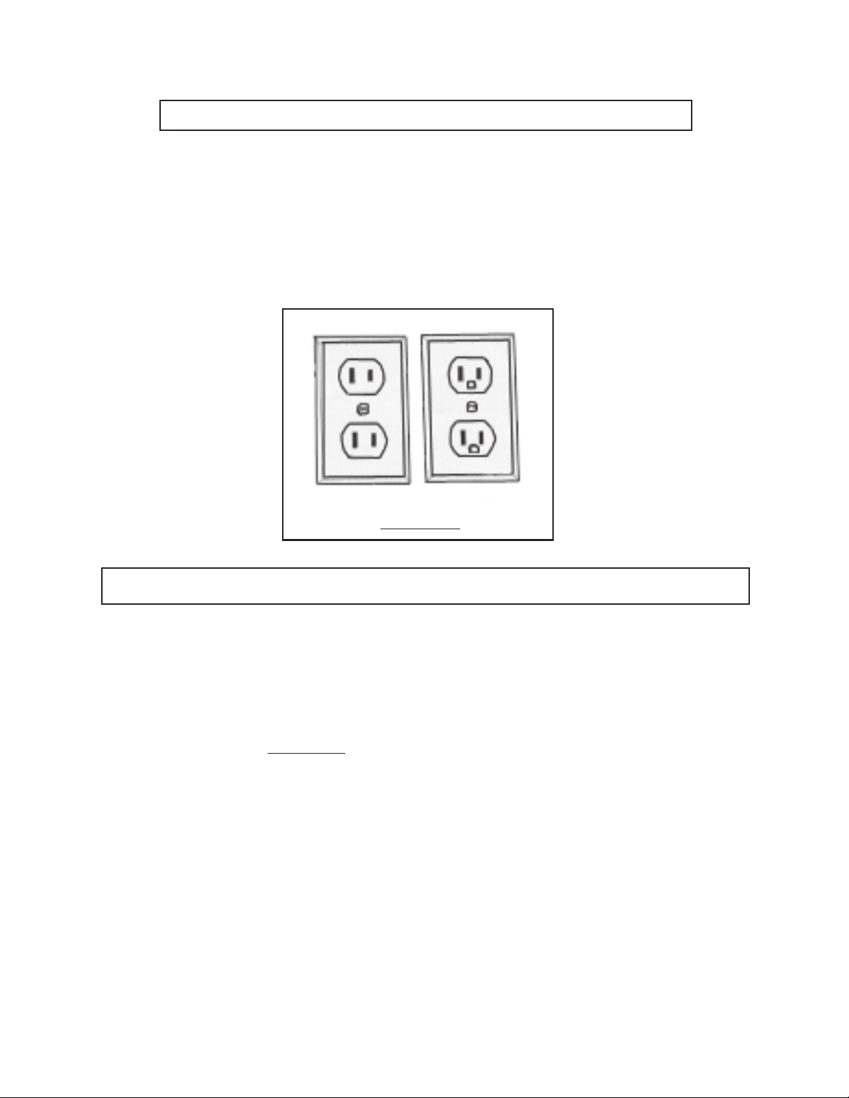
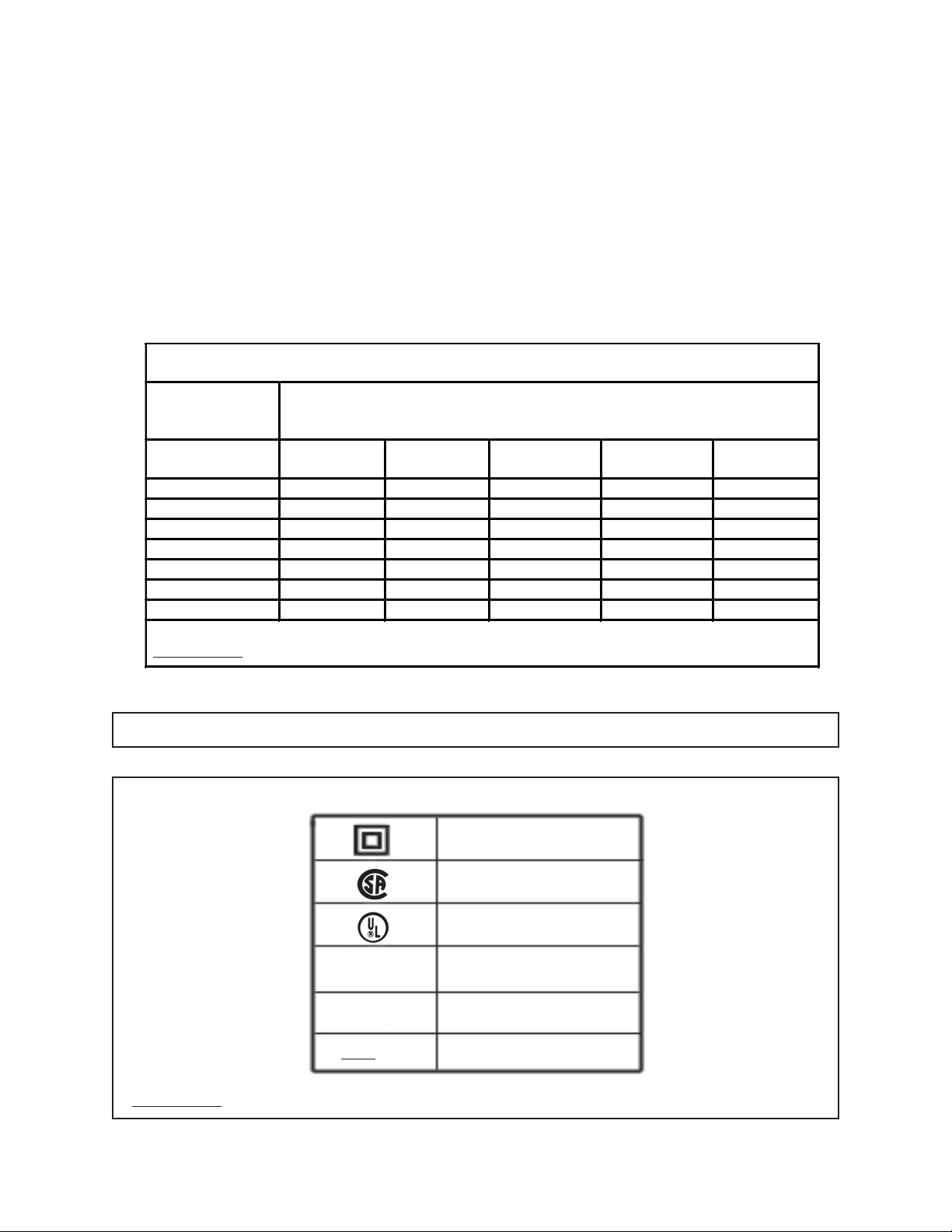
RECOMMENDED MINIMUM WIRE GAUGE FOR EXTENSION CORDS*
(120 VOLT)
NAMEPLATE
AMPERES
At Full Load
25
Feet
0 – 2.0 18 18 18 18 16
2.1 – 3.4 18 18 18 16 14
3.5 – 5.0 18 18 16 14 12
5.1 – 7.0 18 16 14 12 12
7.1 – 12.0 18 14 12 10 -
12.1 – 16.0 14 12 10 - -
16.1 – 20.0 12 10 - - * Based on limiting the line voltage drop
FIGURE C
to five volts at 150% of the rated amperes.
EXTENSION CORD LENGTH
50
Feet
75
Feet
100
Feet
150
Feet
SYMBOLOGY
Double Insulated
Canadian Standards
Association
Underwriters
Laboratories, Inc.
V ~
A
n
o
xxxx/min.
FIGURE D
SKU 91130 For technical questions, please call 1-800-444-3353. Page 10
Volts Alternating Current
Amperes
No Load Revolutions
per Minute (RPM)
Page 11

PRODUCT FEATURES
Part # Description Part # Description
8B Key 14C Feather Board
9B Power Switch (not shown) 16C Upper Fence
10B Safety Cover 24C Dust Port Box
14B Large Lock Knob 26C Dust Port
20B Main Table 27C Miter Gauge
21B Feather Board 14D Height Adjusting Ring
28B Variable Speed Adjustment 15D Collet Assembly Cover
2C Lower Fence 19D Collet Nut
8C Fence Lock Knob 23D Height Adjusting Lock
13C Fence Adjusting Knob 22E Spindle Lock Lever
(16C)
(2C)
(8C)
(21B)
(20B)
(10B / 9B)
(28B)
(14B)
(8B)
(8C)
(13C)
(2C / 16C)
(26C)(24C)
(15D)
(14C)
(8C)
(27C)
(14B)
HEIGHT
ADJUSTMENT
ARROW
(22E)
(14D)
(17D)
(19D)
FIGURE E
(26C)
(23D)(10D)
(13C)
SKU 91130 For technical questions, please call 1-800-444-3353. Page 11
Page 12

ASSEMBLY INSTRUCTIONS
NOTE: For additional references to the parts listed in the following pages, refer to the
Assembly Diagrams on pages 28, 29, 30, 31, and 32.
To Assemble The Base:
1. Place one Table (8A)
upside down
on a level floor surface. Attach a Support
Board 1 (2A) to opposite corners of the Table, and attach a Support Board 2 (1A)
to the two remaining opposite corners of the Table using Screws (3A), Washers
(6A), and Plastic Nuts (7A). Repeat this procedure for the remaining two Tables
(8A). (See Figure F.)
2. Hold Support Leg 1 (4A) and Support Leg 2 (9A) together with their mounting
holes aligned. Then, align the mounting holes of the Support Legs with the three
mounting holes in Support Board 1 (2A) and Support Board 2 (1A). Secure the
Support Legs to the Support Boards, using Screws (3A), Washers (6A), and
Plastic Nuts (7A). (See Figure F.)
SUPPORT LEG 1
(4A)
SUPPORT LEG 2
(9A)
SCREW (3A)
WASHER (6A)
PLASTIC NUT (7A)
END
VIEW
(UPSIDE DOWN)
TABLE (8A)
FRONT
VIEW
(UPSIDE DOWN)
TABLE (8A)
FRONT
VIEW
(RIGHT SIDE UP)
SUPPORT
BOARD 2
(1A)
TABLE (8A)
SUPPORT
BOARD 1
(2A)
FIGURE F
SKU 91130 For technical questions, please call 1-800-444-3353. Page 12
Page 13

3. With assistance, turn the assembled Base
right side up
. (See Figure F.)
4. With assistance, move the assembled Base to the floor surface where the Router
will be used. NOTE: Make sure the floor surface is dry, flat, level, and
sturdy enough to support the weight of the Router, workpieces, and any
additional tools and equipment. Use the four Support Legs 2 (9A) as a tem-
plate to mark four places where mounting holes will be drilled in the floor
surface. Then, temporarily set the assembled Base aside. (See Figure F.)
5. Drill four mounting holes of appropriate size into the floor surface. Then move
the assembled Base back to its original position, making sure to align the mounting holes in the Support Legs 2 (9A) with the mounting holes drilled into the floor.
6. Secure the four Support Legs 2 (9A) to the floor surface, using four bolts, lock
washers, and nuts (not included). NOTE: It is recommended to use expansion
anchor bolts for concrete and lag bolts for wooden floors.
7. Slightly loosen the Screws (3A) on the Support Legs 2 (9A) of the assembled
Base. Adjust the height of each Support Leg 2 (9A) until the Base is level. Then,
retighten the Screws. (See Figure F.)
To Assemble The Mid-Section:
1. Stand the two Support Legs (12B) upright. Then place the Left Side Board (17B)
against the
inside
edge of the Support Legs. Align the four mounting holes in the
Left Side Board with the four mounting holes in the Support Legs, and secure the
Left Side Board to the Support Legs with Screws (15B), Washers (16B), and
Plastic Lock Nuts (18B). (See Figure G.)
2. Place the Right Side Board (25B) against the
inside
edge of the two Support
Legs. Align the four mounting holes in the Right Side Board with the four mounting holes in the Support Legs, and secure the Right Side Board to the Support
Legs with Screws (15B), Washers (16B), and Plastic Lock Nuts (18B).
(See Figure G.)
LEFT SIDE BOARD (17B)
SCREW (15B)
WASHER (16B)
PLASTIC NUT (18B)
SUPPORT LEG
(12B)
RIGHT SIDE BOARD (25B)
SUPPORT LEG
(12B)
FRONT VIEW REAR VIEWFIGURE G
SKU 91130 For technical questions, please call 1-800-444-3353. Page 13
Page 14

To Attach The Mid-Section To The Body:
1. With assistance, place the Mid-Section of the Router Table on top of the Base.
(See Figure H.)
2. Align the two mounting holes at the bottom of each Support Leg (12B) with the
two mounting holes at each end of the Table (8A). (See Figure H.)
3. Insert a Square Head Screw (11B)
holes at both ends of the Table (8A) and through the two mounting holes in each
Support Leg (12B). Then secure the Mid-Section to the Body, using four Large
Lock Knobs (14B) and Large Washers (13B). (See Figure H.)
SUPPORT LEG (12B)
LARGE LOCK KNOB
(14B)
LARGE WASHER
SQUARE HEAD SCREW
(11B)
TABLE
(8A)
FIGURE H
upward
(13B)
through each of the two mounting
SUPPORT
LEG
(12B)
SIDE VIEW
To Attach The Power Switch Assembly And Variable Speed Adjustment:
1. Insert the Power Switch Assembly (9B) and Variable Speed Adjustment (28B)
into the mounting hole located on the left end of the Left Side Board (17B). Then
secure the Power Switch Assembly and Variable Speed Adjustment to the Left
Side Board, using Screws (15B), Washers (16B), and Plastic Lock Nuts (18B).
(See Figure I, next page.)
To Attach The Main Table:
1. Place four Corner Washers (19B) on the ends of the two Support Legs (12B),
and align the three mounting holes in each Corner Washer with the three mounting holes at each end of the Support Legs. (See Figure J, next page.)
2. Place the Main Table (20B) on top of the four Corner Washers and two Support
Legs (12B), and align the eight mounting holes in the Main Table with the eight
SKU 91130 For technical questions, please call 1-800-444-3353. Page 14
Page 15

SCREW (15B)
WASHER (16B)
LEFT SIDE BOARD (17B)
POWER
SWITCH
PLASTIC LOCK NUT (18B)
(9B)
VARIABLE
SPEED
ADJUSTMENT
(28B)
FIGURE I
mounting holes in the Corner Washers and Support Legs. (See Figure J.)
3. Insert eight Square Head Bolts (22B) downward through the eight mounting
holes in the Main Table (20B) and through the eight mounting holes in the Corner
Washers (19B) and Support Legs (12B). Then secure the Main Table to the
Support Legs, using Large Washers (13B) and Plastic Lock Nuts (18B).
(See Figure J.)
SQUARE HEAD BOLT (22B)
FIGURE J
NUT (24B)
NUT (24B)
LARGE WASHER (13B)
PLASTIC LOCK NUT
(18B)
HEX SCREW
(23B)
MAIN
TABLE
(20B)
SKU 91130 For technical questions, please call 1-800-444-3353. Page 15
Page 16

4. Screw a Nut (24B) downward on each of the
Hex Screws downward through the
Table (20B). Make sure the Nuts are above the mounting holes. Then, screw a
Nut (24B) upward on each of the eight Hex Screws to secure the Hex Screws to
the Main Table. (See Figure J.)
eight
eight
Hex Screws (23B). Insert the
mounting holes located on the Main
To Attach The Motor Assembly:
1. Lower the Adjustment Board (17D) with its pre-attached Motor Assembly through
the top of the Main Table (20B). Position the Adjustment Board and Motor
Assembly so that its Power Cord is on the left hand side and the Spindle Lock
Lever (22E) is on the right hand side. Continue lowering the Adjustment Board
until it sits on the eight Hex Screws (23B). (See Figures J and K.)
ADJUSTMENT BOARD (17D)
SCREW
(16D)
..
..
MAIN
TABLE
(20B)
MOTOR
ASSY.
FIGURE K
2. NOTE: The height of the Adjustment Board (17D) can be adjusted by inserting
a hex wrench (not included) through the Adjustment Board and adjusting each
Hex Screw (23B) individually. Once adjusted, secure the Adjustment Board to
the Main Table (20B) with four Screws (16D). (See Figures J and K.)
SPINDLE
LOCK
LEVER
(22E)
To Attach The Fence:
1. The Upper Fence (16C) is supplied with
channel (groove) of the Upper Fence. The furthest
Upper Fence are for attaching the two Fence Supports (10C) to the Upper
Fence. The middle
Upper Fence. (See Assembly Diagram C.)
SKU 91130 For technical questions, please call 1-800-444-3353. Page 16
two
Nuts are for attaching the Dust Port Box (24C) to the
six
Nuts (11C) already fitted to one
two
Nuts on each end of the
Page 17

2. Position the Upper Fence (16C) on the Main Table (20B).
3. Use two Screws (9C) to attach a Fence Support (10C) to the back of the Upper
Fence (16C), making sure to use two of the outermost pre-fitted Nuts (11C) in the
channel of the Upper Fence. Do not tighten yet. Repeat this procedure for the
remaining Fence Support (See Assembly Diagram C.)
4. Slide the two Fence Supports (10C) along the Upper Fence (16C) until the hole
in the horizontal leg of the Fence Supports is above the
channel
at the rear of the Main Table (20B).
transverse
(right angle)
(See Assembly Diagram C and Figure L.)
TRANSVERSE CHANNEL
MAIN TABLE
(20B)
TRANSVERSE
CHANNEL
FIGURE L
5. NOTE: The screw heads of the Screws (22C) locate in a channel under the Main
Table (20B). This channel holds the Screws and prevents the Screws from
turning when the Fence Locking Knobs (8C) are tightened or loosened.
(See Assembly Diagram C.)
6. Insert the screw head of a Screw (22C) into the channel under the Main Table
(20B) so that the threaded portion of the Screw passes through the hole in a
Fence Support (10C). Tighten the Screw, using a Fence Lock Knob (8C) and
Large Washer (7C). (See Assembly Diagram C.)
7. Tighten the Screws (9C) holding the Fence Support (10C) to the Upper Fence
(16C). (See Assembly Diagram C.)
8. Repeat Steps #6 and #7 at the other end of the Upper Fence (16C).
To Attach The Dust Port Assembly And Protector:
1. Position the Dust Port Assembly (26C) and Protector (23C) to the middle of the
SKU 91130 For technical questions, please call 1-800-444-3353. Page 17
Page 18

rear of the Upper Fence (16C), using the remaining two pre-fitted Nuts (11C) in
the channel of the Upper Fence and two Screws (9C).
(See Assembly Diagram C and Figure M.)
PROTECTOR
(23C)
UPPER FENCE (16C)
DUST PORT ASSY.
(26C)
FENCE LOCK KNOB
(8C)
FIGURE M
To Install And Remove Collets:
1. WARNING! Always make sure the Power Switch (9B) is in its “OFF”
position and the Power Cord/Plug (1B) is unplugged from its electrical
outlet before making any adjustments to the Router Table.
2. The Router is equipped with a 1/4” Collet (18D) and a 1/2” Collet (24D).
3. The Collet (18D, 24D) may need to be changed to allow use of larger or smaller
diameter router bits (not included).
4. NOTE: When changing Collets (18D, 24D) or when changing router bits, the
height of the Motor Assembly should be raised to the maximum height to gain full
access to the Collet Nut (19D).
5. Unlock the Height Adjustment Lock (23D) by rotating it in a counterclockwise
direction, using the end of the Wrench (21D) provided.
(See Figure N, next page.)
6. Remove the Collet Assembly Cover (15D) by removing the two inner Screws
(1D) on the Cover and lifting the Cover away from the Height Adjusting Ring
(14D). If necessary, clean off any saw dust and debris which may have built up
from previous cutting operations. (See Figure N.)
SKU 91130 For technical questions, please call 1-800-444-3353. Page 18
Page 19

WRENCH
(21D)
HEIGHT
ADJUSTMENT
LOCK
(23D)
COLLET
ASSEMBLY
COVER
(15D)
HEIGHT
ADJUSTING
RING
(14D)
COLLET
NUT
(19D)
WRENCH
(21D)
COLLET
NUT
(19D)
FIGURE N
7. Use the Wrench (21D) to turn the Collet Nut (19D) in a
counterclockwise
direction
while pulling and holding the Spindle Lock Lever (22E) forward. Then, remove
the Collet Nut. (See Figures K and N.)
8. Remove the existing Collet (18D, 24D) from the assembly, and make sure to
install the correct size Collet (1/4” or 1/2”) for the router bit to be used. Then,
finger tighten
the Collet Nut (19D) back onto the assembly. (See Figure O.)
COLLET
(18D, 24D)
COLLET
NUT
(19D)
FIGURE O
SKU 91130 For technical questions, please call 1-800-444-3353. Page 19
Page 20

9. Make sure to insert the shaft of the router bit all the way into the Collet
(18D, 24D). (See Figure P.)
10. Tighten the Collet Nut (19D) by pulling and holding the Spindle Lock Lever (22E)
forward while screwing the Collet Nut in a clockwise direction.
(See Figures K and P.)
ROUTER BIT
(NOT INCLUDED)
ROUTER BIT
COLLET
NUT
(19D)
FIGURE P
11. Replace the Collet Assembly Cover (15D). (See Figure N.)
12. Adjust the depth of cut to the desired depth by turning the Height Adjustment
Ring (14D). Then, use the Height Adjustment Lock (23D) to lock the setting in
place. NOTE: Make sure the Height Adjustment Lock is aligned in a locking
position and that the router bit is firmly secured. (See Figure N.)
To Adjust The Depth Of Cut:
1. Loosen the Height Adjustment Lock (23D) by turning it in a
counterclockwise
direction, using the Wrench (21D) provided. (See Figure Q.)
WRENCH
(21D)
HEIGHT
ADJUSTMENT
LOCK
(23D)
ADJUSTMENT
TOOL
(27D)
ADJUSTMENT
BOARD
(17D)
FIGURE Q
SKU 91130 For technical questions, please call 1-800-444-3353. Page 20
Page 21

2. Fit the Adjustment Tool (27D) in the corresponding slots of the Height Adjusting
Ring (14D) and turn the Ring in a
counterclockwise
for a lesser depth of cut. (See Figure Q.)
clockwise
direction for a deeper depth of cut or
3. NOTE: The Height Adjustment Ring (14D) is marked with a straight arrow point-
ing to the edge of the Adjustment Board (17D). The Adjustment Board (17D) is
marked with ten corresponding lines. When setting the depth of cut, always align
the arrow on the Height Adjustment Ring with one of the ten lines on the Adjustment Board. (See Figure Q.)
4. To determine the depth of cut, use a ruler to measure the distance between the
base of the Main Table (20B) and the tip of the router bit.
5. Once the depth of cut is acquired, align the Height Adjustment Lock (23D) and
turn the Lock in a
clockwise
direction to lock. (See Figure Q.)
6. NOTE: Always make a trial cut on scrap wood to ensure the correct depth of cut
has been selected.
To Attach And Adjust The Feather Boards:
1. To attach the
first
Feather Board (14C), slide the heads of two Square Head
Screws (15C) into a channel (groove) on the front of the Upper Fence (16C).
Then mount the Feather Board against the Upper Fence, and secure it with two
Large Washers (7C) and two Fence Lock Knobs (8C). (See Figure R.)
UPPER FENCE (16C)
FEATHER BOARD (14C) FEATHER BOARD
SQUARE
HEAD
SCREW
(15C)
(14C)
FENCE
LOCK
KNOB
(8C)
LARGE
WASHER
(7C)
UPPER FENCE (16C)
FIGURE R
SKU 91130 For technical questions, please call 1-800-444-3353. Page 21
Page 22

2. Attach the
do so, insert two Square Head Screws (11B) upward through the Feather Board.
Then slide the head of both Screws into the keyhole slot located in the channel
used for the Miter Gauge (27C). Secure the Feather Board to the Main Table,
using two Large Washers (13B) and two Large Lock Knobs (14B).
(See Figure S.)
second
Feather Board (21B) horizontally to the Main Table (20B). To
LARGE LOCK KNOB
(14B)
LARGE WASHER
(13B)
SQUARE HEAD SCREW (11B)
FEATHER BOARD (21B)
FEATHER
BOARD
(21B)
MITER GAUGE CHANNEL
MAIN TABLE (20B)
FIGURE S
3. NOTE: The Feather Boards (14C, 21B) are designed to hold the workpiece in
place and prevent kickback. To adjust the Feather Boards, simply loosen the
Lock Knobs (8C, 14B) and move the Feather Boards into the workpiece. Then,
retighten the Lock Knobs. Make sure the “feathers” of the Feather Boards allow
easy feed of the workpiece and help prevent kickback. (See Figures R and S.)
To Attach The Miter Gauge:
1. The Miter Gauge (27C) slides horizontally along the Main Table (20B) and is
designed for edging and miter cuts in the workpiece. (See Figure T, next page.)
2. To attach the Miter Gauge (27C), simply slide its bar into the Miter Gauge Channel on the Main Table (20B). (See Figure T.)
3. To adjust the Miter Gauge (27C) to the desired angle, loosen the Fence Lock
Knob (8C) and rotate the Miter Gauge to the desired angle from 0 degrees to 45
degrees. Then, retighten the Fence Lock Knob. (See Figure T.)
SKU 91130 For technical questions, please call 1-800-444-3353. Page 22
Page 23

4. NOTE: For more convenience when making miter cuts, the Upper Fence (16C)
may be moved to its furthest position away from the router bit. (See Figure T.)
MAIN TABLE (20B)
MITER GAUGE
CHANNEL
MITER GAUGE
(27C)
FENCE
LOCK
KNOB
(8C)
FENCE ADJUSTING
KNOB
(13C)
UPPER FENCE (16C)
FIGURE T
To Adjust The Upper Fence:
1. The Upper Fence (16C) can be adjusted according to the size of the workpiece
and the application being performed. To do so, loosen the four Fence Adjusting
Knobs (13C). (See Figure T.)
2. Slide the Upper Fence (16C) forward or backward to the desired position.
Use the gauge on the Main Table (20B) to determine the distance from the Upper
Fence to the center of the router bit. Then, retighten the four Fence Adjusting
Knobs (13C). (See Figure T.)
To Adjust The Speed (RPM):
1. NOTE: Using the correct speed for the job increases the life of the router bit and
can also affect the surface finish on the workpiece being cut. The Router Table
features a Variable Speed Adjustment (28B) and may be adjusted from approximately 8,400 RPM to 27,800 RPM (no load). (See Figure U, next page.)
2. The Dial of the Variable Speed Adjustment (28B) is numbered from 1 to 6, with 1
being the
slowest
speed and 6 being the
fastest
speed. It is recommended to
determine the optimum speed by making a trial cut in a scrap piece of wood.
(See Figure U.)
3. IMPORTANT: Do not attempt to adjust the speed while the Router Table is
running. Turn off the machine, and allow it to come to a complete stop
before
adjusting the speed. (See Figure U.)
SKU 91130 For technical questions, please call 1-800-444-3353. Page 23
Page 24

SAFETY COVER
(10B)
VARIABLE
SPEED ADJ.
(28B)
KEY (8B)
POWER SWITCH
(9B)
FIGURE U
To Turn On The Router Table:
1. Connect the Power Cord/Plug (1B) to the nearest grounded, 120 volt, electrical
outlet.
2. Depress the Key (8B), and lift up on the Safety Cover (10B). Then, depress the
Power Switch (9B) to its “ON” position. (See Figure U.)
3. To turn off the Router Table, simply depress the Safety Cover (10B) to snap it
shut. This pushes the “OFF” button underneath the Safety Cover and cuts off the
power. (See Figure U.)
4. To lock the Power Switch (9B) and prevent unauthorized use, close the Safety
Cover (10B) and remove the Key (8B) by pulling it out. Make sure to store the
Key in a safe location out of reach of children. (See Figure U.)
To Operate The Router Table:
1. Insert and secure the desired Collet (18D, 24D) and router bit.
2. Make all necessary adjustments to the Router Table.
3. Make sure the Power Switch (9B) is in its “OFF” position. Then, connect the
Power Cord/Plug to the nearest grounded, 120 volt, electrical outlet.
4. Depress the Power Switch (9B) to its “ON” position.
SKU 91130 For technical questions, please call 1-800-444-3353. Page 24
Page 25

5. Feed the workpiece gradually from right to left against the rotation of the cutter.
Keep the feed rate constant. Feeding the workpiece too quickly will slow the
Motor of the machine. Feeding the workpiece too slowly will cause burns to the
workpiece.
6. On very hard wood or large cuts it may be necessary to make more than one
pass at progressive depth settings until the desired depth of cut is made.
7. When finished, depress the Safety Cover (10B) to turn off the Router Table.
Then, unplug the Power Cord/Plug from its electrical outlet.
INSPECTION, MAINTENANCE, AND CLEANING
1. CAUTION! Always turn the Power Switch (9B) to its “STOP” position
and unplug the Power Cord (1B) from its 120 volt electrical outlet before
performing any inspection, adjustments, maintenance, or cleaning.
2. BEFORE EACH USE, inspect the general condition of the Router Table. Check
for loose screws, misalignment or binding of moving parts, cracked or broken
parts, damaged electrical wiring, loose router bit, and any other condition that
may affect its safe operation. If abnormal noise or vibration occurs, have the
problem corrected before further use.
Do not use damaged equipment.
3. DAILY: With a soft brush, cloth, or vacuum, remove all sawdust and debris from
the Router Table, particularly, the machine’s Dust Port (26C) and Main Table
(20B), Then, use a premium quality, lightweight machine oil to lubricate all moving parts. Do not use solvents or caustic agents to clean the Router Table.
PLEASE READ THE FOLLOWING CAREFULLY
THE MANUFACTURER AND/OR DISTRIBUTOR HAS PROVIDED THE PARTS LIST AND ASSEMBLY
DIAGRAM IN THIS MANUAL AS A REFERENCE TOOL ONLY. NEITHER THE MANUFACTURER OR
DISTRIBUTOR MAKES ANY REPRESENTATION OR WARRANTY OF ANY KIND TO THE BUYER THAT HE
OR SHE IS QUALIFIED TO MAKE ANY REPAIRS TO THE PRODUCT, OR THAT HE OR SHE IS QUALIFIED
TO REPLACE ANY PARTS OF THE PRODUCT. IN FACT, THE MANUFACTURER AND/OR DISTRIBUTOR
EXPRESSLY STATES THAT ALL REPAIRS AND PARTS REPLACEMENTS SHOULD BE UNDERTAKEN BY
CERTIFIED AND LICENSED TECHNICIANS, AND NOT BY THE BUYER. THE BUYER ASSUMES ALL
RISK AND LIABILITY ARISING OUT OF HIS OR HER REPAIRS TO THE ORIGINAL PRODUCT OR
REPLACEMENT PARTS THERETO, OR ARISING OUT OF HIS OR HER INSTALLATION OF REPLACEMENT
PARTS THERETO.
SKU 91130 For technical questions, please call 1-800-444-3353. Page 25
Page 26

PARTS LIST A
Part # Description Qty. Part # Description Qty.
1A Support Board 2 2 6A Washer (5) 60
2A Support Board 1 2 7A Plastic Lock Nut (M5) 60
3A Screw (M5 x 12) 60 8A Table 3
4A Support Leg 1 4 9A Support Leg 2 4
5A Leg Washer 4
PARTS LIST B
Part # Description Qty. Part # Description Qty.
1B Power Cord & Plug 1 18B Plastic Lock Nut (M6) 16
2B Cord Clip 3 19B Corner Washer 4
3B Cord Protector 2 20B Main Table 1
4B Switch Box Base 1 21B Feather Board 1
5B Plastic Nail 2 22B Square Head Bolt (M6 x 30) 8
6B Locking Buckle 1 23B Hex Screw (M6 x 27) 8
7B Plastic Screw (2.9 x 9) 1 24B Nut (M6) 18
8B Key 1 25B Right Side Board 1
9B Power Switch 1 26B Plastic Lock Screw (2.9 x 13) 4
10B Safety Cover 1 27B Switch Box Cover 1
11B Square Head Screw (M6 x 40) 6 28B Variable Speed Adjustment 1
12B Support Leg 2 29B Plastic Screw (3.5 x 13) 4
13B Large Washer (6) 14 30B Power Cord (16AWG) 1
14B Large Lock Knob 4 31B Terminal 2
15B Screw (M6 x 16) 10 32B Press Board 2
16B Washer (6) 8 33B Terminal Block 1
17B Left Side Board 1
PARTS LIST C
Part # Description Qty. Part # Description Qty.
1C Lower Fence Left End Cap 2 15C Square Head Screw (M6 x 40) 2
2C Lower Fence 2 16C Upper Fence 1
3C Lower Fence Right End Cap 2 17C Locking Piece 4
4C Self-Locking Screw (4.8 x 13)6 18C Upper Fence Left End Cap 1
5C Pin 1 19C Screw (M5 x 12) 4
6C Screw (M5 x 25) 1 20C Fence Support Fixing Washer 2
7C Large Washer (5) 8 21C Plastic Lock Nut (M5) 5
8C Fence Lock Knob 6 22C Square Head Screw (M6 x 30) 2
9C Screw (M6 x 16) 6 23C Protector 1
10C Fence Support 2 24C Dust Port Box 1
11C Head Nut 6 25C Plastic Screw (M2.9 x 9) 2
12C Upper Fence Right End Cap 1 26C Dust Port 1
13C Fence Adjusting Knob 4 27C Miter Gauge (Not Shown) 1
14C Feather Board 1
SKU 91130 For technical questions, please call 1-800-444-3353. Page 26
Page 27

PARTS LIST D
Part # Description Qty. Part # Description Qty.
1D Screw (M4 x 10) 10 15D Collet Assy. Cover 1
2D Plastic Lock Nut 4 16D Screw (M4 x 12) 4
3D Washer (4) 4 17D Adjustment Board 1
4D End Running Knot 1 18D Collet (1/2”) 1
5D Slip Knot 1 19D Collet Nut 2
6D Snail Knot 1 20D C-Ring 2
7D Block Ring (45) 1 21D Wrench 1
8D Large Spring 1 22D Small Spring 1
9D Slip Groove 1 23D Height Adj. Lock 1
10D Turning Piece 1 24D Collet (1/4”) 1
11D Steel Bead (5) 6 25D Small Washer B 1
12D Locking Piece 1 26D Small Washer C 1
13D Partial Axis 1 27D Adjustment Tool 1
14D Height Adjusting Ring 1 28D Large Washer 1
29D Hex Screws 4
PARTS LIST E
Part # Description Qty. Part # Description Qty.
1E Plastic Bolt (M3.5 x 25) 2 19E Mat Knot 1
2E Fan Cover 1 20E Block Ring (37) 1
3E Carbon Brush 2 21E Cover 1
4E Brush Holder 2 22E Spindle Lock Lever 1
5E Insert Piece 4 23E Screw 2
6E Blue Non-Burning Knot 1 24E Rotator 1
7E Connecting Line 1 25E Screw (M4 x 65) 2
8E Motor Shell 1 26E Washer (4) 5
9E Stator Armature 1 27E Bearing Knot 1
10E Spring Washer (4) 9 28E Terminal 2
11E Bearing (608Z) 1 29E Wire 2
12E Block Ring (20) 1 30E Brush Box Knot 2
13E Block Cover 1 31E Clip 1
14E Locking Piece 1 32E Terminal Block 2
15E Wiring Spring 1 33E Washer (4) 1
16E Screw (M4 x 20) 4 34E Earth Line Cover 1
17E Bearing (6904RS) 1 35E Screw (M4 x 8) 1
18E Dust Block Piece 1 36E Tie Strip (88mm) 3
SKU 91130 For technical questions, please call 1-800-444-3353. Page 27
Page 28

ASSEMBLY DIAGRAM A
individually as replacement parts.
9A
1A
2A
3A
4A
5A
8A
7A
6A
NOTE: Some parts are listed and shown for illustration purposes only, and are not available
SKU 91130 For technical questions, please call 1-800-444-3353. Page 28
Page 29

ASSEMBLY DIAGRAM B
28B
29B
30B
31B
individually as replacement parts.
32B
23B
22B
14B
24B
13B
21B
24B
20B
13B
18B
25B
11B
19B
18B
17B
15B
16B
13B
18B
26B
27B
24B
33B
14B
13B
31B
1B
3B 2B
4B
5B
7B 6B
9B 8B
11B 10B
12B
NOTE: Some parts are listed and shown for illustration purposes only, and are not available
SKU 91130 For technical questions, please call 1-800-444-3353. Page 29
Page 30

8C
7C
15C
ASSEMBLY DIAGRAM C
22C
21C
20C
19C
18C
17C
16C
23C
14C
13C
4C
12C
11C
10C
9C
7C6C
9C
24C
25C26C
7C
8C
1C
2C
5C
3C
4C
27: MITER GAUGE NOT SHOWN.
NOTE: Some parts are listed and shown for illustration purposes only, and are not available individually as replacement parts.
SKU 91130 For technical questions, please call 1-800-444-3353. Page 30
Page 31

24D
ASSEMBLY DIAGRAM D
1D
2D
3D
26D
27D
19D
20D
25D
4D
5D
28D
6D
individually as replacement parts.
7D
8D
9D
10D
11D
12D
13D
14D
17D
18D
19D
20D
15D
1D
16D
21D
1D
23D
22D
29D
NOTE: Some parts are listed and shown for illustration purposes only, and are not available
SKU 91130 For technical questions, please call 1-800-444-3353. Page 31
Page 32

ASSEMBLY DIAGRAM E
30E
29E
1E
23E
24E
25E
27E
26E
28E
11E
10E
9E
36E
31E8E
7E
4E
5E
3E
2E
replacement parts.
32E
6E
purposes only, and are available individually as
22E
12E
15E
13E
4E
20E 21E
19E
18E
34E
17E
16E
33E
26E
10E
35E
NOTE: Some parts are listed and shown for illustration
SKU 91130 For technical questions, please call 1-800-444-3353. Page 32
 Loading...