

Page 1

16” LASER LEVEL
®
WITH 360
ASSEMBLY & OPERATING INSTRUCTIONS
°°
° ROT ATING HEAD
°°
90980
3491 Mission Oaks Blvd., Camarillo, CA 93011
Visit our Web Site at www.harborfreight.com
Copyright© 2003 by Harbor Freight Tools®. All rights reserved. No por tion of this manual or
any artwork contained herein may be reproduced in any shape or form without the
express written consent of Harbor Freight Tools.
For technical questions and replacement parts please call 1-800-444-3353.
Page 2
THANK YOU for choosing a HARBOR FREIGHT TOOLS product. For future reference, please
complete the owner’s record below:
Model
______________ Serial No._____________ Purchase Date_______________
SAVE THE RECEIPT, WARRANTY AND THESE INSTRUCTIONS. It is important that you read the
entire manual to become familiar with the unit BEFORE y ou begin assembly.
Technical Specifications
Construction: Machined aluminum housing with 3 vials; horizontal,
vertical and bulls-eye.
Level Dimensions: 15-5/8” L x 13/16” W x 2” H
Diode Wav e Length: 650 +/- 10 N.M.
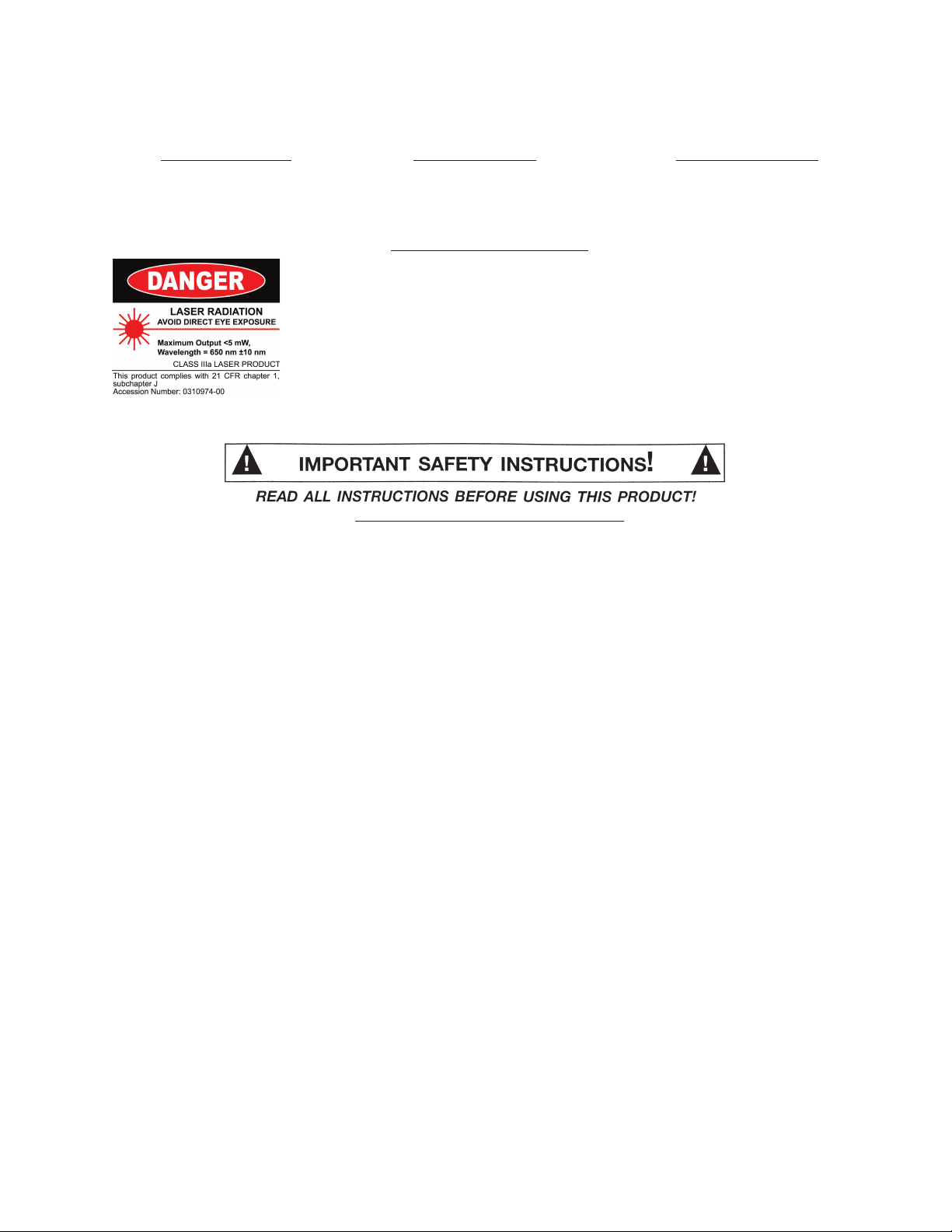
FDA Appro ved: Class III-A, Certification #0310974-00
Batteries: (2) “AAA” included
Tripod: 41” folding
Laser Accuracy: +/- .05% approximately
Features: Projects up to 1,500 ft. (Laser dot is visible up to 1500 Ft.*)
*Dependent on illumination of work area.
Safety Warnings and Precautions
WARNING: When using product, basic safety precautions should always be followed to
reduce the risk of personal injury and damage to equipment.
Read all instructions before using this product!
1. Keep work area clean. Cluttered areas invite injuries.
2. Observe work area conditions. Keep work area well lit.
3. Store idle equipment. When not in use, products must be stored in a dry location to inhibit
damage from moisture and salt air.
4. Check for damaged parts. Bef ore using any product, an y part that appears damaged should be
carefully checked to determine that it will operate properly and perform its intended function. Check
for any brok en or damaged parts and any other conditions that may affect its operation. Replace
or repair damaged or worn parts immediately.
5. Replacement parts and accessories. When servicing, use only identical replacement par ts.
Use of any other parts will void the warranty.
6. Always check hardware and assembled parts after assembling. All connections should be
tight and hardware tightened.
7. Keep children away. Children must never be allowed in the work area. Do not let them handle
the Laser Level.
8. Do not direct the laser beam into the eyes of any person or animal, this may cause severe
injury to the eye. Do not look directly into the beam during operation.
9. Laser light when reflected off of a mirrorlike surface can cause serious eye damage.
10. Use only Batteries of the type recommended-size “AAA”.
11. Do not mix old and new batteries. Do not use different types of batteries; do not use
rechargeable with alkaline batteries.
SKU 90980 Page 2
REV 03/04 REV 02/05
Page 3

12. Make certain to switch the Laser Level to the “OFF” position when adjusting or when
changing the batteries.
13. Use the right tool for the job. There are certain applications for which this tool w as designed. Do
not modify this tool and do not use this tool for a purpose for which it was not intended.
14. Remove batteries if the Laser Level is not used for a long period of time.
15. Do not operate tool if under the influence of alcohol or drugs. Read warning labels on
prescriptions to determine if your judgment or reflexes are impaired while taking drugs. If there is
any doubt, do not operate the tool.
Note: Always switch to a fresh batter y when tool performance begins to diminish. This is a
delicate instrument, do not drop or jar the Laser Level.
Warning: The warnings, cautions, and instructions discussed in this instruction manual cannot
cover all possible conditions and situations that may occur. It must be understood by
the operator that common sense and caution are factors which cannot be built into this
product, but must be supplied by the operator.
Assembly/ Operation
Your Laser Level will require some assembly prior to use. It is important that you read the entire
manual to become familiar with the product BEFORE you use the Laser Level. Before assembling and
operating the Laser Level be sure that you have all parts described in the
Diagram
located on the last pages of this manual.
Parts List and Assembly
Figure 2
Knob (14)
latch
Knob (17)
Figure 1
leg of
T ripod (15)
Plastic Body (5)
Tripod slot
arms
1. Unfold the Tripod (15) by pulling out on the Tr ipod arms. Turn the Knob (17) to lock the arms in
place-see
2. The legs of the Tripod (15) can be raised or lowered by lifting the latch on the body of the Tripod
(15) and sliding the leg in or out to the desired height-see
place to secure the Leg into position. Repeat for the remaining two legs.
3. Set the Tripod on a flat surface. Once the Tripod (15) is set up, you can raise and lower the
Rotating Head (7) by turning the Handle (18) located at the top of the Tripod (15) -see
Wind the Handle (18) clockwise to raise the Rotating Head (7) and counterclockwise to lower the
Rotating Head (7) -see
4. Initial Leveling of the Rotating Head (7):
Turn the three Adjusting Knobs (16) one at a time to level the Rotating Head (7). Keep turning the
Adjusting Knobs (16) until the Bulls-Eye Bubble (19) floats exactly in the center of the circle. If
you are out of level, the air bubble will float to the side of the Bulls-Eye Bubble-see
Figure 1.
Figure 3.
Figure 1
. Push the latch down into
Figure 3
Figure 4.
Note: The Bulls-Eye Bubble (19) is intended for initial leveling of the Rotating Head (7) only.
After placing the Plastic Body (5) into the tripod slot, further leveling should be done
using the Horizontal Bubble (4) as a reference.
SKU 90980 Page 3
REV 03/04
.
Page 4

Rotating
Head (7)
Handle (18)
Vertical Bubble (3)
Horizontal Bubble (4)
T ripod (15)
Adjusting Knob (16)
Figure 3
5. Set the Plastic Body (5) into the slot in the Tripod-see
Figure 4
Figure 2
. Tighten down
the Knob (14) on the top of the Tripod to secure the Plastic Body (5) in placesee
Figure 2
6.
, page 3.
How to Level the Laser:
Note: The numbers here are only for reference , the knobs are not numbered.
a. Set the level parallel to knobs ‘1’ and ‘2’ as shown in
‘2’ until the Horizontal Bubble (4) is in the center .
b. Turn the level 90°. It should now be over knob ‘3’ as shown in
knob ‘3’ until the Horizontal Bubble (4) is again in the center .
c. Turn the lev el bac k 90°, to the position shown in
(4) should still be in the center. If it is not, repeat the steps abo ve . If , after repeated
attempts, the level is still uneven check all mountings to ensure nothing is loose and
that the Plastic Body (5) is properly seated in the tripod slot.
Leveling A.
Leveling B
Adjust knobs ‘1’ and
Leveling B
. The Horizontal Bub ble
. Adjust
7. Once the Laser Level is set in the Tripod, you may set the laser to the type of
beam you wish to use. The laser projects up to 1,500 feet. Set the Lens
Fixture (11) “Down”; and this mode will fix the Level Laser beam to a beam
splitter (-) mode. The beam splitter mode will project a horizontal line. Set the
Lens Fixture (11) to the top mode and this mode will set the Laser Level beam
to a dot (.)-see
Figure 5
. Turn the Laser Level “ON” by pressing the “ON/OFF”
button (9) -see Figure 5. Be careful not to point the Laser Level at anyone.
8. Once you have leveled the Level Laser
in the Tripod (15), you can use it for
many applications. Rotating the
Rotating Head (7) with the laser ON
and set to the beam splitter (-) mode,
you can set a line of equal height in a
room to verify alignment of pictures,
Lens Fixture (11)
electrical plugs, or shelving. The Laser
Level can also be used to set a level
for any surface while providing a bright
beam to mark your settings by.
Figure 5
Install batteries to match
diagram
Leveling A
Leveling B
Battery Cover (13)
On/Off Button (9)
PLEASE READ THE FOLLOWING CAREFULLY
THE MANUFACTURER AND/OR DISTRIBUTOR HAS PROVIDED THE PARTS DIAGRAM IN THIS MANUAL AS A
REFERENCE TOOL ONLY. NEITHER THE MANUFACTURER NOR DISTRIBUTOR MAKES ANY REPRESENTATION OR
WARRANTY OF ANY KIND TO THE BUYER THAT HE OR SHE IS QUALIFIED TO MAKE ANY REPAIRS TO THE PRODUCT OR
THAT HE OR SHE IS QUALIFIED TO REPLACE ANY PARTS OF THE PRODUCT. IN FACT, THE MANUFACTURER AND/OR
DISTRIBUTOR EXPRESSLY STATES THAT ALL REPAIRS AND PARTS REPLACEMENTS SHOULD BE UNDERTAKEN BY
CERTIFIED AND LICENSED TECHNICIANS AND NOT BY THE BUYER. THE BUYER ASSUMES ALL RISK AND LIABILITY
ARISING OUT OF HIS OR HER REPAIRS TO THE ORIGINAL PRODUCT OR REPLACEMENT PARTS THERETO, OR ARISING
OUT OF HIS OR HER INSTALLATION OF REPLACEMENT PARTS THERETO.
SKU 90980 Page 4
REV 03/04
Page 5

Warning: Always make certain the laser is off before adjusting or changing batteries.
Installing and Removing Batteries
1. The Laser Level uses two (2) “AAA” batteries. Remove the Battery Cover (13)
located under the On/Off Button (9) -see Figure 5. Remo ve the old batteries and insert two
new batteries. Line the batteries up the same way, so that positive and negative ends match
the diagram on the end of the Laser Level. Replace the Battery Cover (13).
Warning: People with pacemakers should consult with their physician before
using this product; operation of equipment in close proximity to a
heart pacemaker could cause interference or failure of the
pacemaker.
Warning: This product contains or produces a chemical known to the State
of California to cause cancer and birth defects (or other
reproductive harm). (California Health & Safety Code 25249.5 et
seq.)
Unpacking
When unpacking your 16" Laser Le vel with 360
following parts are included. If any parts are missing or broken, please call HARBOR FREIGHT
TOOLS at 1-800-444-3353.
Parts List
Part # Description Quantity Part # Description Quantity
1 Laser Aperture 1 10 Front Cover 1
2 Back Cover 1 11 Lens Fixture 1
3 Vertical Bubble 1 12 Fan Lens 1
4 Horizontal Bubble 1 13 Battery Cover 1
5 Plastic Body 1 14 Knob 1
6 Laser Modules 1 15 Tripod 3
7 Rotating Head 1 16 Adjusting Knob 3
8 Battery Spring 1 17 Knob 1
9 On/Off Button 1 18 Handle 1
Assembly/Parts Diagram
3
18
15
17
2
14
16
° Rotating Leveling Head, check to make sure the
19 Bulls-Eye Bubble 2
19
13
4 5
8
6
12
7
9
11
1
10
Note: Some parts are listed and shown for illustration purposes only and are not available
individually as replacement parts.
SKU 90980 Page 5
 Loading...