

Page 1
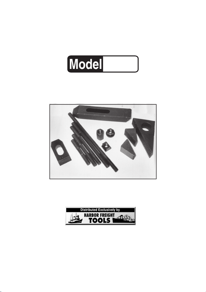
CLAMPING KIT
®
42 PIECES
90752
OPERATING INSTRUCTIONS
(Photograph Shows Only a Partial Assortment of the Clamps,
3491 Mission Oaks Blvd., Camarillo, CA 93011
Visit our W eb site at http://www.harborfreight.com
Copyright © 2003 by Harbor Freight Tools®. All rights reserved. No portion of this
manual or any artwork contained herein may be reproduced in any shape or form
without the express written consent of Harbor Freight Tools.
For technical questions and replacement parts, please call 1-800-444-3353
Studs, and Nuts included in the Kit).
Page 2

Specifications
Item Description
Hardware Material
Clamping Kit Holder
Net Weight
Machined Black Oxide Coated Alloy Steel
3-3/4” X 6-3/4” X 11-5/8”
14.55 Lbs.
Save This Manual
You will need the manual for the safety warnings and precautions, operating and
maintenance procedures, parts list and diagram. K eep your inv oice with this manual.
Write the invoice number on the inside of the front cov er . Keep this manual and the
invoice in a safe and dry place for future reference.
Safety Warnings and Precautions
WARNING: When using product, basic safety precautions should always be f ollowed to reduce the risk of personal injury and damage to equipment.
Read all instructions before using this product!
1. Avoid working alone. If an accident happens, an assistant can bring help.
2. Avoid electrical shock. Use extreme caution when clamping around
uninsulated conductors or bus bars.
3. Keep work area clean. Cluttered areas invite injuries.
4. Avoid damaging equipment. Use only as specified in machine manual that
accompanied the machinery.
5. Observe work area conditions. Don’t expose to rain. Keep work area well
lighted.
7. Keep children away. Children must never be allowed in the work area. Do
not let them handle machines, tools, or extension cords.
6. Store idle equipment. When not in use, tools must be stored in a dry
location to inhibit rust. Always lock up tools and keep out of reach of
children.
8. Dress properly. Do not wear loose clothing or jewelry as they can be
caught in moving parts. Protective, electrically nonconductive clothes and
nonskid footwear are recommended when working. Wear restrictive hair
covering to contain long hair.
9. Use eye and ear protection. Always wear ANSI approved impact safety
goggles.
SKU 90752 Page 2
Page 3

10. Do not overreach. K eep proper footing and balance at all times. Do not reach
over or across machinery, especially while it is moving.
11. Maintain tools with care. Inspect tools periodically and have them replaced,
if damaged, only with identical parts available at Harbor Freight Tools.
12. Use the right tool for the job. Do not attempt to f orce a small tool or
attachment to do the work of a larger industrial tool. There are certain
applications for which this tool was designed. Do not modify this tool and do
not use this tool for a purpose for which it was not intended.
13. Stay alert. Watch what you are doing, use common sense. Do not operate
any tool when you are tired.
14. Check for damaged parts. Before using any tool, any part that appears
damaged should be carefully checked to determine that it will operate
properly and perform its intended function. Check for any broken parts or
mounting fixtures and any other condition that may affect proper operation.
Any part that is damaged should be replaced.
15. Replacement parts and accessories. When servicing, use only identical
replacement parts. Use of any other parts will void the warranty. Only use
accessories intended for use with this tool. Appro v ed accessories are
available from Harbor Freight Tools.
16. Do not operate tool if under the influence of alcohol or drugs. Read
warning labels on prescriptions to determine if your judgment or reflexes are
impaired while taking drugs. If there is any doubt, do not operate the tool.
Warning: The warnings, cautions, and instructions discussed in this instruction manual cannot cover all possible conditions and situations that may occur. It must be understood by the operator that common sense and caution
are factors which cannot be built into this product, but must be supplied by
the operator.
Unpacking
When unpacking, check to make sure the following parts are included. If any
parts are missing or broken, please call Harbor Freight Tools at the number on
the cover of this manual.
SKU 90752 Page 3
Page 4

Operation
The 42 Piece Clamping Kit is for use with a Milling Machine with 1/2” wide table slots.
WARNING! Use the instructions that accompany the Milling Machine (not included)
for operating, safety, and maintenance instructions . The below operating instructions
are only a suggestion for identifying parts and possible uses.
1. After determining what workpiece you will be milling, select the correct length of
Clamping Stud (1), T-Nut (2), Flange Nut (4), or Coupling Nut (5) (not shown), that
is appropriate for the dimensions of your workpiece.
See
Figure A.
2. Y ou can then choose the correct Step Blocks (3) that will help y our workpiece to
be held securely during the milling process. Tighten the Flange Nut (4) (or Coupling
Nut (5), not shown) firmly , until the workpiece can no longer move. After ensuring
that your workpiece is secured properly, proceed with the Milling instructions
(not included). See
Figure A.
Maintenance
General
1. Never leave work unattended. Replace parts back into the Clamping Kit
Holder (7) when finished. (Not shown).
2. Periodically clean all 42 pieces and see that they are free from oil or rust.
3. Keep all parts free from moisture to avoid rust and corrosion.
SKU 90752 Page 4 REV 03/04
Page 5

Parts List
PART# DESCRIPTION QTY.
1
Clamping Studs 8”, 7”, 6”, 5”, 4” & 3” Long (2 ea)
2
T-Nuts M10 X 1.500
3
Step Blocks 1-1/8”, 1-1/2” & 3-9/16” Long (4 ea)
4
Flange Nuts M10 X 1.500
5
Coupling Nuts M10 X 1.500
Slotted Step Clamps 1-15/32” Thick X 1-1/8” W X 1-15/32” L
Slot Size: 1/2” W X 1-1/8” L
47/64” Thick X 1-7/32” W X 4” L
6
7
Clamping Kit Holder (not shown)
Part 6
Part 1
Part 6
Slot Size: 1/2”W X 1-11/16” L
27/32” Thick X 1-7/32” W X 6-1/16” L
Slot Size: 1/2”W X 2-7/16” L
Parts Diagram
(all with M10 X 1.500 Thread)
(all 31/32” Wide)
Part 4
Part 5
Part 3
12
4
12
4
4
2
2
2
1
(Photograph of a Partial Assortment of Parts)
PLEASE READ THE FOLLOWING CAREFULLY
THE MANUFACTURER AND/OR DISTRIBUTOR HAS PROVIDED THE PARTS DIAGRAM
IN THIS MANUAL AS A REFERENCE TOOL ONLY. NEITHER THE MANUFACTURER
NOR DISTRIBUTOR MAKES ANY REPRESENTATION OR WARRANTY OF ANY KIND TO
THE BUYER THAT HE OR SHE IS QUALIFIED TO MAKE ANY REPAIRS TO THE
PRODUCT OR THAT HE OR SHE IS QUALIFIED TO REPLACE ANY PARTS OF THE
PRODUCT. IN FACT, THE MANUFACTURER AND/OR DISTRIBUTOR EXPRESSLY
ST ATES THA T ALL REPAIRS AND PAR TS REPLACEMENTS SHOULD BE UNDER TAKEN
BY CERTIFIED AND LICENSED TECHNICIANS AND NOT BY THE BUYER. THE BUYER
ASSUMES ALL RISK AND LIABILITY ARISING OUT OF HIS OR HER REPAIRS TO THE
ORIGINAL PRODUCT OR REPLACEMENT PARTS THERETO, OR ARISING OUT OF HIS
OR HER INSTALLATION OF REPLACEMENT PARTS THERETO.
NOTE: Some parts are listed and shown for illustration purposes only and are not
available individually as replacement parts.
SKU 90752 Page 5
Part 3
Part 2
 Loading...