

Page 1
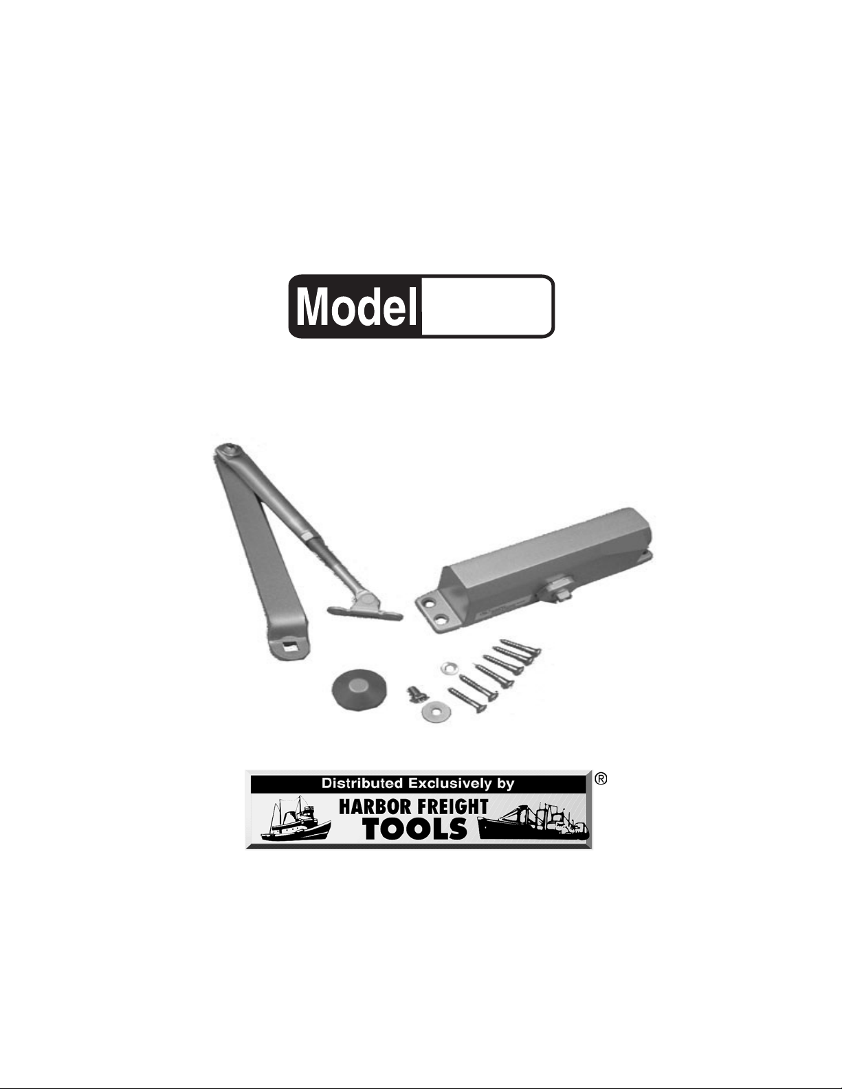
HYDRAULIC DOOR CLOSER
90402
ASSEMBLY AND OPERATING INSTRUCTIONS
3491 Mission Oaks Blvd., Camarillo, CA 93011
Visit our Web site at http://www.harborfreight.com
Copyright © 2003 by Harbor Freight Tools®. All rights reserved. No portion of
this manual or any artwork contained herein may be reproduced in any shape
or form without the express written consent of Harbor Freight Tools.
For technical questions and replacement parts, please call 1-800-444-3353
Page 2

Specifications
Overall Dimensions 7-1/2” L x 2-3/4” H x 2-5/8” W
Arm Dimensions 9-3/4” L, Closed
Mounting Holes 6-7/8” Width Apart (Centers),
15/16” H (Centers)
Maximum Capacity 132 Lbs. (For small & medium doors)
Door Closer Weight 3.4 Lbs.
Save This Manual
You will need the manual for the safety warnings and precautions, assembly instructions,
operating and maintenance procedures, parts list and diagram. Keep your invoice with this
manual. Write the invoice number on the inside of the front cover. Keep the manual and
invoice in a safe and dry place for future reference.
Safety Warnings and Precautions
WARNING: When using product, basic safety precautions should always be followed
to reduce the risk of personal injury and damage to equipment.
Read all instructions before using this product!
1. Keep work area clean. Cluttered areas invite injuries.
2. Observe work area conditions. Don’t expose to rain. Keep work area well lighted.
3. Keep children away. Children must never be allowed in the work area. Do not let
them handle the Door Closer.
4. Store idle equipment. When not in use, products must be stored in a dry location to
inhibit rust. Always lock up products and keep out of reach of children.
5. Use the right product for the job. Do not attempt to force a small product to do the
work of a larger industrial product. There are certain applications for which this
product was designed. It will do the job better and more safely at the rate for which it
was intended. Do not modify this product and do not use this product for a purpose for
which it was not intended.
6. Dress properly. Do not wear loose clothing or jewelry as they can be caught in
moving parts. Protective, electrically non-conductive clothes and non-skid footwear
are recommended when working. Wear restrictive hair covering to contain long hair.
7. Use eye and ear protection. Always wear ANSI approved impact safety goggles
during assembly.
8. Do not overreach. Keep proper footing and balance at all times.
Page 2SKU 90402
Page 3

9. Maintain products with care. Keep products clean for better and safer
performance.
10. Stay alert. Watch what you are doing, use common sense. Do not assemble the
Door Closer when you are tired.
11. Check for damaged parts. Before using any product, any part that appears
damaged should be carefully checked to determine that it will operate properly and
perform its intended function. Check for alignment and binding of moving parts; any
broken parts or mounting fixtures; and any other condition that may affect proper
operation. Any part that is damaged should be properly repaired or replaced by a
qualified technician.
12. Replacement parts and accessories. When servicing, use only identical
replacement parts. Use of any other parts will void the warranty.
13. Do not assemble the Door Closer if under the influence of alcohol or drugs.
Read warning labels if taking prescription medicine to determine if your judgment or
reflexes are impaired while taking drugs. If there is any doubt, do not assemble the
product.
14. Maintenance. For your safety, service and maintenance should be performed
regularly by a qualified technician.
Warning: The warnings, cautions, and instructions discussed in this instruction manual
cannot cover all possible conditions and situations that may occur. It must be understood by the operator that common sense and caution are factors which cannot be
built into this product, but must be supplied by the operator.
Unpacking
When unpacking, check to make sure the parts listed on page 5 are included. If any parts
are missing or broken, please call Harbor Freight Tools at the number on the cover of this
manual as soon as possible.
Page 3SKU 90402
Page 4

Operation and Assembly
This Closer is designed to be mounted on the door, on the pull side. Use the template
below for regular arm installations for doors opening to 180O.
Arm
Shoe (#4)
Frame
1-1/32”
5-1/8”
2-3/8”
Arm Screw (#2) and
Lock Washer (#3)
3/4”
Shaft attaches here
Hydraulic Housing (#8)
6-7/8”
Door
Holes for
Wood Screws
(#7) or Machine
Screws (#9)
Refer to the Assembly Drawing on page 5. Note: Diagram above is showing right hand opening; left
hand opening would layout in opposite direction.
1. After selecting the degree of opening, mark four holes on the door for the Hydraulic Housing (#8)
and two holes on the frame for the Arm Shoe (#4). Use the template above.
2. Drill pilot holes in the frame and door for the Wood Screws (#7), or drill and tap holes for the
Machine Screws (#9).
FIGURE 1
Index
Point
Speed Adjusting Valve
Hinge
Left Hand Opening Right Hand Opening
3. Making sure the Speed Regulating Screw is toward the hinge edge of the door, mount the
Hydraulic Housing (#8) on the door. See FIGURE 2.
4. Using the Arm Screw (#2) and the Lock Washer (#3), attach and tighten the arm of the Shaft (#5)
to the top of the Hydraulic Housing (#8). Make sure you secure it at the proper index point dependent upon whether it is a right or left hand opening door. See FIGURE 1.
5. Using two Wood Screws (#7), attach the Arm Shoe (#4) to the Door Frame. See Template above.
6. Loosen the Arm Screw (#2) and the Lock Washer (#3) to adjust the length of the arm so that when
the door is closed the main arm will remain at a right angle (90O). Tighten the Arm Screw (#2) and the
Lock Washer (#3).
7. Secure the Cover Cap (#1) on the bottom of the Hydraulic Housing (#8) by gently
threading it on.
Hydraulic
Housing (#8)
Speed Adjusting Valve
Hinge
Adjustments
Door closing speed adjustment was factory set for the
average weight door. If more closing power is needed,
change the arm position from the center hole to the hole
closest to the main arm.
Adjust speed by using the regulating screws as illustrated
in FIGURE 2.
Page 4SKU 90402
FIGURE 2
Closing speed
regulating screw
Fast
Latching speed
regulating screw
Slow
Closing
Speed
Latch
Page 5

Assembly Drawing
8
Attaches to
door frame
(See Template)
4
2
5
Attaches to Hydraulic
Housing (#8) at the
Arm Screw (#2)
THE MANUFACTURER AND/OR DISTRIBUTOR HAS PROVIDED THE PARTS DIAGRAM IN THIS
MANUAL AS A REFERENCE TOOL ONLY. NEITHER THE MANUFACTURER NOR DISTRIBUTOR MAKES ANY REPRESENTATION OR WARRANTY OF ANY KIND TO THE BUYER THAT HE
OR SHE IS QUALIFIED TO MAKE ANY REPAIRS TO THE PRODUCT OR THAT HE OR SHE IS
QUALIFIED TO REPLACE ANY PARTS OF THE PRODUCT. IN FACT, THE MANUFACTURER
AND/OR DISTRIBUTOR EXPRESSLY STATES THAT ALL REPAIRS AND PARTS REPLACEMENTS
SHOULD BE UNDERTAKEN BY CERTIFIED AND LICENSED TECHNICIANS AND NOT BY THE
BUYER. THE BUYER ASSUMES ALL RISK AND LIABILITY ARISING OUT OF HIS OR HER
REPAIRS TO THE ORIGINAL PRODUCT OR REPLACEMENT PARTS THERETO, OR ARISING
OUT OF HIS OR HER INSTALLATION OF REPLACEMENT PARTS THERETO.
3
9
1
6
Parts List
Part No. Description
1 Cover Cap
2 Arm Screw
3 Lock Washer
4 Arm Shoe
5 Shaft
6 Washer
7 Wood Screw (6)
8 Hydraulic Housing
9 Machine Screw (4)
PLEASE READ THE FOLLOWING CAREFULLY
7
NOTE: Some parts are listed and shown for illustration purposes only and are not available
individually as replacement parts.
Page 5SKU 90402
 Loading...