

Page 1
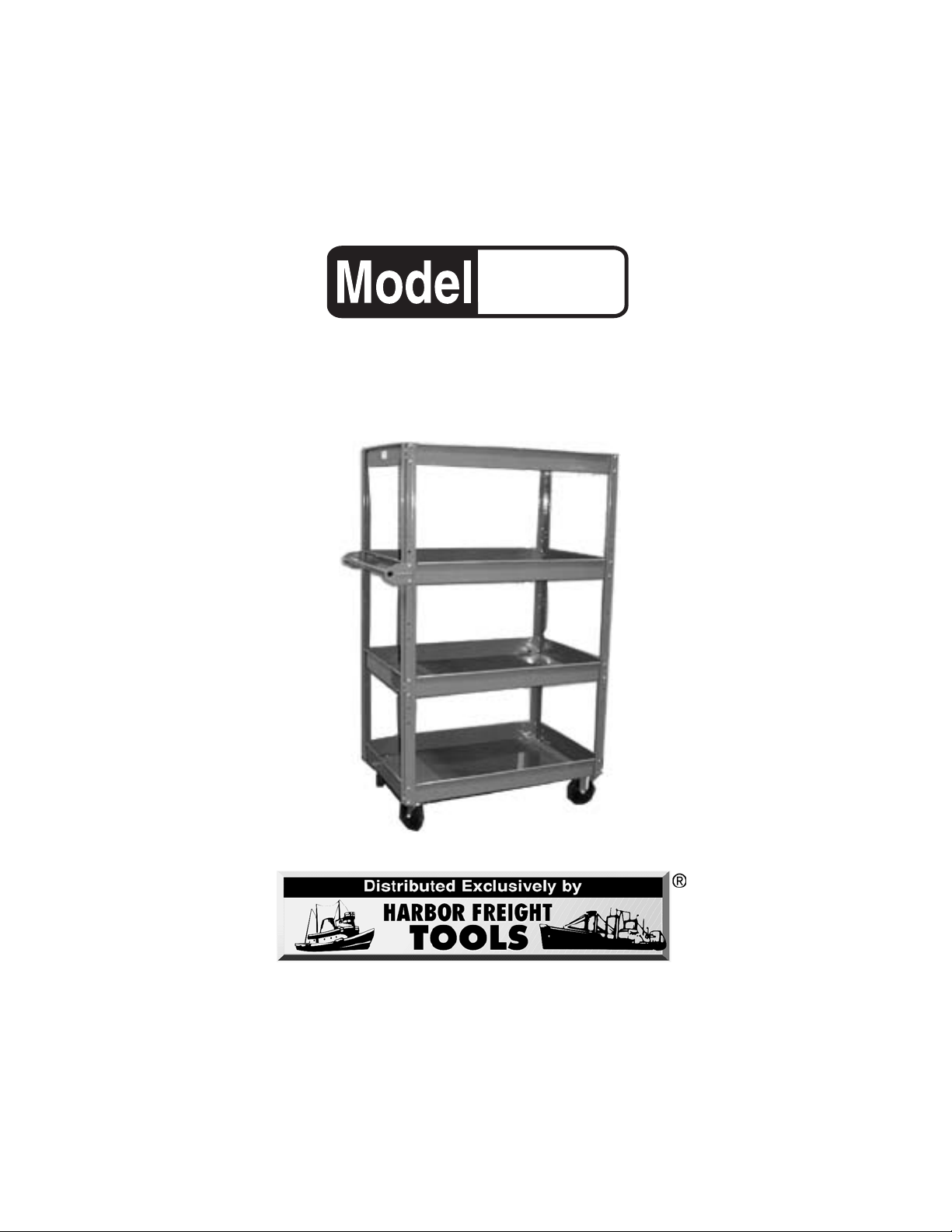
4 TIER STOCKER
SERVICE CART
90160
ASSEMBLY AND OPERATING INSTRUCTIONS
3491 Mission Oaks Blvd., Camarillo, CA 93011
Visit our Web site at http://www.harborfreight.com
Copyright © 2003 by Harbor Freight Tools®. All rights reserved. No portion of
this manual or any artwork contained herein may be reproduced in any shape
or form without the express written consent of Harbor Freight Tools.
For technical questions and replacement parts, please call 1-800-444-3353
Page 2

Specifications
Weight Capacity 450 Lbs.Overall (if evenly distributed), 112 Lbs. Per Shelf
Overall Dimensions 60” H x 39” L x 24-1/8” W
Tray Dimensions 35-1/8” x 22-7/8” (Inside)
Castors (4) 5” x 1-3/4” - (2 Swivel Castors)
Save This Manual
You will need the manual for the safety warnings and precautions, assembly instructions,
operating and maintenance procedures, parts list and diagram. Keep your invoice with this
manual. Write the invoice number on the inside of the front cover. Keep the manual and
invoice in a safe and dry place for future reference.
Safety Warnings and Precautions
WARNING: When using product, basic safety precautions should always be followed
to reduce the risk of personal injury and damage to equipment.
Read all instructions before using this product!
1. Keep work area clean. Cluttered areas invite injuries.
2. Observe work area conditions. Don’t expose to rain. Keep work area well lighted.
3. Keep children away. Children must never be allowed in the work area. Do not let
them play with or ride on the Cart.
4. Store idle equipment. When not in use, the Cart must be stored in a dry location to
inhibit rust.
5. Use the right product for the job. Do not attempt to force a small Cart to do the
work of a larger industrial Cart. There are certain applications for which this Cart was
designed. It will do the job better and more safely at the rate for which it was intended.
Do not modify this Cart and do not use this Cart for a purpose for which it was not
intended.
6. Dress properly. Do not wear loose clothing or jewelry as they can be caught in
moving parts. Protective, electrically non-conductive clothes and non-skid footwear
are recommended when working. Wear restrictive hair covering to contain long hair.
7. Use eye protection. Always wear ANSI approved impact safety goggles during
assembly.
8. Do not overreach. Keep proper footing and balance at all times.
Page 2SKU 90160
Page 3

9. Maintain products with care. Keep the Cart clean for better and safer performance.
The handle must be kept clean, dry, and free from oil and grease at all times.
10. Stay alert. Watch what you are doing, use common sense. Do not operate the Cart
when you are tired.
11. Check for loose and damaged parts. Before using the Cart, any part that appears
damaged should be carefully checked to determine that it will operate properly and
perform its intended function. Check for alignment and binding of moving parts; any
broken parts or mounting fixtures; and any other condition that may affect proper
operation. Any part that is damaged should be properly repaired or replaced by a
qualified technician.
12. Replacement parts and accessories. When servicing, use only identical
replacement parts. Use of any other parts will void the warranty.
13. Do not operate the Cart if under the influence of alcohol or drugs. Read warning
labels if taking prescription medicine to determine if your judgment or reflexes are
impaired while taking drugs. If there is any doubt, do not operate the Cart.
14. Maintenance. For your safety, service and maintenance should be performed
regularly by a qualified technician.
15. Operate and store the Cart on a flat, dry, level surface.
Warning! Do not exceed the Service Cart’s maximum capacity of 450 Lbs.
Warning! Weight on all four of the Trays must be evenly distributed and balanced for safety.
Warning: The warnings, cautions, and instructions discussed in this instruction manual
cannot cover all possible conditions and situations that may occur. It must be understood by the operator that common sense and caution are factors which cannot be
built into this product, but must be supplied by the operator.
Unpacking
When unpacking, check to make sure the parts listed on page 6 are included. If any parts
are missing or broken, please call Harbor Freight Tools at the number on the cover of this
manual as soon as possible.
Page 3SKU 90160
Page 4

Assembly
While following the assembly instructions on page 5, use the three FIGURES below and the
Assembly Drawing on page 7.
FIGURE 1
Note: Part Names are
listed on page 6.
A
C
A
B
E
D
Position 1
G
H
F
FIGURE 2
Caster Plate
Castor Mounting Plate (D)
Handle Detail
Handle (H)
Post (C)
FIGURE 3
Upper/Middle
Tray (A)
Page 4SKU 90160
Page 5

Assembly (continued)
Note: You will need a 7/16” open end wrench and a flat screwdriver (both not included).
Refer to FIGURES 1, 2, & 3, on page four and the Assembly Drawing on page 7.
1. Bolt the Bottom Tray (B) to all four Posts (C) using (16) 1/4-20 x 1/2” machine screws and
nuts.
2. Working your way up the Posts (C) from the bottom, attach the two middle
Upper/Middle Trays (A) to the posts using (16) 1/4-20 x 1/2” machine screws and nuts per
tray. Do not attach two of the bolts on each side for the Handle. See “Position 1” in
FIGURE 1 on page 4.
3. Bolt the Upper, Upper/Middle Tray (A) to the Posts (C) using (16) 1/4-20 x 1/2” machine
screws and nuts.
Note: When mounting the Castors (next step) make sure the Swivel Castors (F) are mounted
on the same side as the Handle.
4. Refering to the Detail insert on the Assembly Drawing on page 7 and FIGURE 2), place
one of the Castor Mounting Plates (D) between the Castor Plate ( FIGURE 2) and the
Bottom Tray (B). Hold one of the Swivel Castors (F) so that the holes match up and attach
with (16) 1/4-20 x 1/2” machine screws, (16) split washers, and (16) nuts (see the Detail insert
on the Assembly Drawing on page 7 and FIGURE 2). Repeat with the other
Swivel Castor (F) making sure it is on the same side as the Handle will be.
5. Mount the two Rigid Castors (E) on the opposite side using the same instructions above
in number 4.
6. At “Position 1” in FIGURE 1 on page 4, bolt one Handle Bracket (G) through the Post (C)
and the Upper/Middle Tray (A) and secure it using 1/4-20 x 1/2” machine screws and nuts.
(See Handle Detail in FIGURE 1).
7. Insert the Handle Tube (H) in the attached Handle Bracket (G). Then, place the second
Handle Bracket (G) onto the Handle Tube (H) and bolt to the other side of the
Post (C) and the Upper/Middle Tray (A) and secure it using 1/4-20 x 1/2” machine screws
and nuts.
8. Tighten all nuts and bolts.
Operation
For maximum safety:
1. Do not exceed the weight capacities listed in the Specifications chart on page 2.
2. Do not allow children or pets to ride on the Cart.
3. Only operate and park the Cart on flat, dry, level surfaces.
4. This Cart was designed to be pushed by an operator, walking slowly behind the unit. Make
sure the Swivel Castors (F) are on the same side as the Handle.
Warning! Weight on all four of the Trays must be evenly distributed and balanced.
Page 5SKU 90160
Page 6

Parts List
Part No. Description Qty.
A Upper/Middle Tray 3
B Bottom Tray 1
C Post 4
D Castor Mounting Plate 2
E Rigid Castor 2
F Swivel Castor 2
G Handle Bracket 2
H Handle Tube 1
I Hardware Package 1
Maintenance
1. Periodically tighten all of the hardware.
2. Make sure the castors are free of all dirt, debris, or grease.
PLEASE READ THE FOLLOWING CAREFULLY
THE MANUFACTURER AND/OR DISTRIBUTOR HAS PROVIDED THE PARTS DIAGRAM IN THIS
MANUAL AS A REFERENCE TOOL ONLY. NEITHER THE MANUFACTURER NOR DISTRIBUTOR MAKES ANY REPRESENTATION OR WARRANTY OF ANY KIND TO THE BUYER THAT HE
OR SHE IS QUALIFIED TO MAKE ANY REPAIRS TO THE PRODUCT OR THAT HE OR SHE IS
QUALIFIED TO REPLACE ANY PARTS OF THE PRODUCT. IN FACT, THE MANUFACTURER
AND/OR DISTRIBUTOR EXPRESSLY STATES THAT ALL REPAIRS AND PARTS REPLACEMENTS
SHOULD BE UNDERTAKEN BY CERTIFIED AND LICENSED TECHNICIANS AND NOT BY THE
BUYER. THE BUYER ASSUMES ALL RISK AND LIABILITY ARISING OUT OF HIS OR HER
REPAIRS TO THE ORIGINAL PRODUCT OR REPLACEMENT PARTS THERETO, OR ARISING
OUT OF HIS OR HER INSTALLATION OF REPLACEMENT PARTS THERETO.
NOTE: Some parts are listed and shown for illustration purposes only and are not available
individually as replacement parts.
Page 6SKU 90160
Page 7

Assembly Drawing
Detail
(B)
(D)
Castor Plate
Split Washer
Nut
Page 7SKU 90160
 Loading...