

Page 1
TOUCH-UP GUN
Model
00086
SET UP AND OPERATING INSTRUCTIONS
Diagrams within this manual may not be drawn proportionally.
Due to continuing improvements, actual product may differ slightly from the product described herein.
Distributed exclusively by Harbor Freight Tools®.
3491 Mission Oaks Blvd., Camarillo, CA 93011
Visit our website at: http://www.harborfreight.com
Read this material before using this product.
Failure to do so can result in serious injury.
SAVE THIS MANUAL.
Copyright© 1997 by Harbor Freight Tools®. All rights reserved. No portion of this
manual or any artwork contained herein may be reproduced in any shape or form
without the express written consent of Harbor Freight Tools.
For technical questions or replacement parts, please call 1-800-444-3353.
Page 2
SAVE THIS MANUAL
You will need this manual for the safety instructions,
assembly and operating instructions and parts list. Put it in
a safe, dry place for future reference. Keep your invoice
with this manual. Write the invoice number on the
inside front cover.
READ ALL INSTRUCTIONS
BEFORE OPERATING THE
TOUCH-UP GUN
SPECIFICATIONS
Characteristic Value
Minimum Operating Air Pressure 33 PSI
Maximum Operating Air Pressure 50 PSI
Cup Paint Volume 7 oz.
Hose Size 3/8”
Material Output 2.8 CFM @ 30 PSI - 4.0 CFM @ 50 PSI
Air Inlet 1/4” NPS
SAFETY WARNINGS & CAUTIONS
1. KEEP WORK AREA CLEAN. Cluttered areas invite injuries.
2. KEEP CHILDREN AWAY. All children should be kept away from the work area. Don't let
them handle tool.
3. DO NOT OPERATE THE TOUCH-UP GUN IF UNDER THE INFLUENCE OF ALCOHOL
OR DRUGS. Read warning labels on prescriptions to determine if your judgment or
reexes are impaired while taking drugs. If there is any doubt, do not attempt to operate.
4. DO NOT SPRAY NEAR OPEN FLAMES, PILOT LIGHTS IN STOVES OR HEATERS,
OR ANY OTHER HEAT SOURCE. Most solvents and coatings are highly ammable,
particularly when sprayed. Always make sure there is adequate ventilation. Extinguish
all cigarettes when painting or cleaning. Industrial applications must follow OSHA
requirements.
5. READ ALL INFORMATION CONCERNING COATING PRODUCTS AND CLEANING
SOLVENTS. Chlorinated solvents, e.g. 1-1-1 Trichloroethane and Methylene Chloride
(also known as methyl chloride) can chemically react with aluminum and may explode.
Many paint sprayers contain aluminum. If you are in any doubt what-so-ever, contact
the solvent or coating manufacturer.
6. MATERIALS USED WHEN PAINTING AND CLEANING MAY BE HARMFUL OR FATAL
IF INHALED AND/OR SWALLOWED. Once again, when spraying, always make sure
there is adequate ventilation. Use a mask or respirator when painting.
7. CHECK ALL SEALS BEFORE CONNECTING TO AIR SUPPLY. Make sure lid is fully
attached to cup, retaining ring is screwed past the rst thread, air pressure plug is
tightened fully, and air supply tube is rmly attached. Never release the lid while the cup
is pressurized.
8. USE EYE PROTECTION. Coatings will cause eye irritation. Wear ANSI approved
chemical splash safety goggles. Goggles are available from Harbor Freight Tools.
When cleaning, be especially careful as solvents can be forcibly ejected from uid and
air passages.
REV 09d
Page 2SKU 00086 For technical questions, please call 1-800-444-3353.
Page 3

9. DRESS SAFELY. Protective gloves and non-skid footwear or safety shoes are
recommended when working with and operating the Touch-Up Gun. Don't wear loose
clothing or jewelry. They can get caught in moving parts. Also, wear a protective hair
covering to prevent long hair from getting caught in the Touch-Up Gun.
10. DON'T OVERREACH. Keep proper footing and balance at all times.
11. STAY ALERT. Watch what you are doing. Use common sense. Do not operate any tool
when you are tired.
12. CHECK DAMAGED PARTS. Before using any tool, any part that is damaged should
be carefully checked to determine that it will operate properly and perform its intended
function. Check for alignment of moving parts, breakage of parts, and other conditions
that may affect its operation.
13. REPLACEMENT PARTS AND ACCESSORIES. When servicing, use only identical
replacement parts. Only use accessories intended for use with this Touch-Up Gun.
Approved accessories are available from Harbor Freight Tools.
14. STORE IDLE EQUIPMENT. When not in use, Touch-Up Gun should be cleaned and
stored, fully assembled, in a dry location to reduce rust. For safety, keep out of reach of
children.
15. MAINTAIN TOOLS WITH CARE. Keep tools clean for better and safer performance.
Follow instructions for lubricating, cleaning and changing accessories. Keep handles
dry, clean and free from oil and grease.
16. OUTDOOR EXTENSION CORDS. When air compressor is used outdoors, use only
rounded jacket extensions cords intended for outside use. See manufacturer’s manual
for the AWG required for the compressor’s amperage draw.
17. BE AWARE OF AIR HOSES AND THEIR CONNECTIONS. Don’t trip over hoses. Make
sure all connections are tight. Keep an eye out for any leaks which should be repaired
immediately.
18. BE AWARE OF OTHER PEOPLE. Never spray directly at people or animals.
UNPACKING
The Touch-Up Gun needs minor assembly. If any parts are missing or broken, please call
Harbor Freight Tools at the number on the cover of this manual.
Item # Description Qty
A Spray Unit 1
B Canister Unit 1
C Repair Kit 1
Page 3SKU 00086 For technical questions, please call 1-800-444-3353.
Page 4
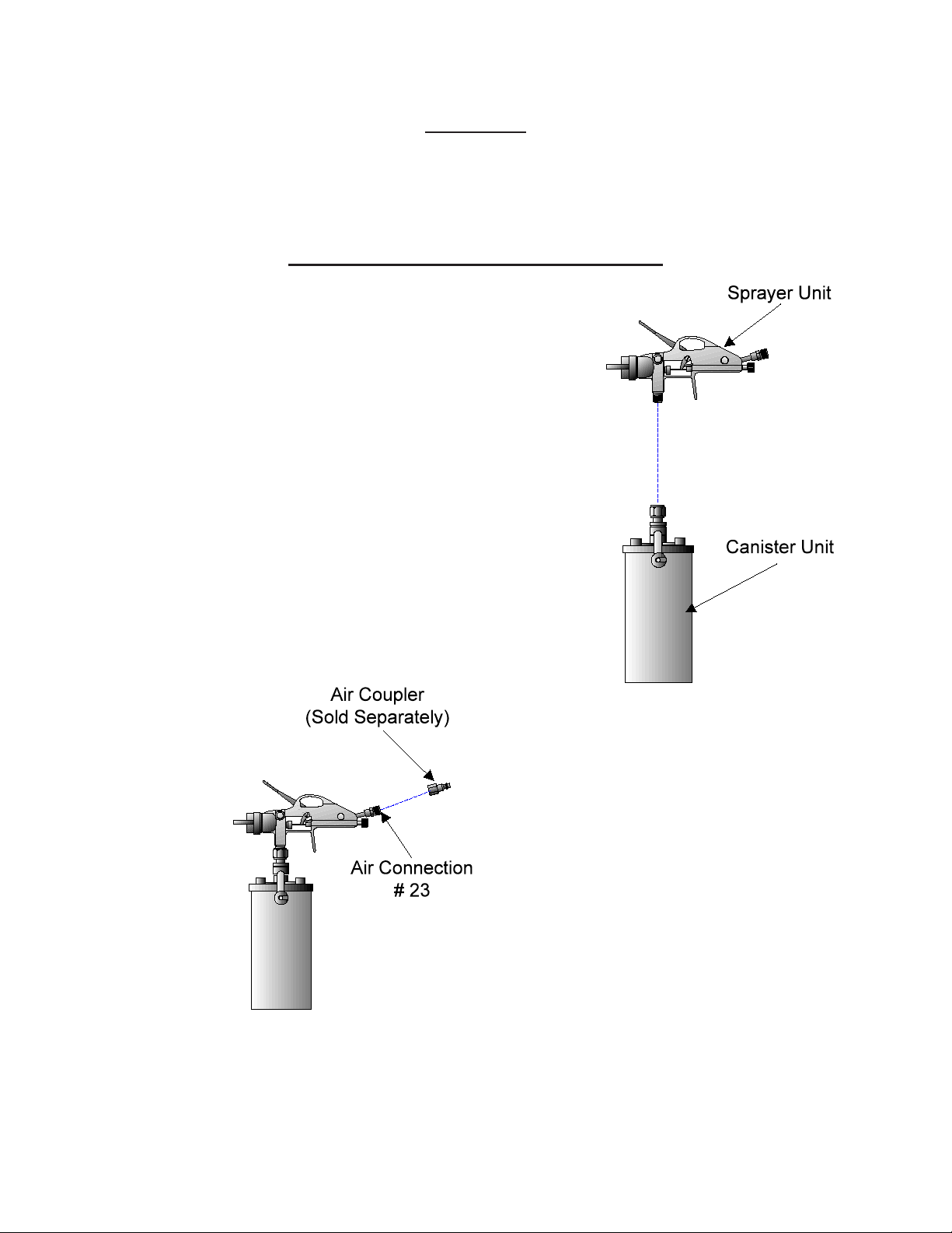
ASSEMBLY
Connect the Spray Unit to the Canister Unit as shown in Figure 1.
BEFORE YOU USE YOUR TOUCH-UP GUN
A coupler is required to connect the Touch-Up Gun to an air
compressor. Select the coupler, e.g. ¼” “M” style NPT, etc. that
mates with the end of the air hose you are using, and screw
it onto the AIR CONNECTION (#23) located at the end of the
Touch-Up Gun’s handle (see Figure 2).
Figure 2 -- Attaching Air Coupler
Figure 1 -- Connecting the
Spray Unit and Canister
Page 4SKU 00086 For technical questions, please call 1-800-444-3353.
Page 5

OPERATION
Setup
Refer to Figure 3 for the location of parts called out in this section.
Figure 3 -- Operation Diagram
Step 1. Move the LEVER (#29) counterclockwise until the YOKE (#30) is free from the CUP
LOCKS (#35).
Step 2. Lift and remove the Paint Gun from the CUP (#34).
Step 3. Prepare the paint or coating per the manufacturer’s instructions for air spray guns.
Step 4. Fill the cup up to the ¾-full mark shown in Figure 4. DO NOT OVERFILL!
Step 5. Lower and replace the Paint
Gun onto the CUP.
Step 6. Align the YOKE with the CUP
LOCKS and move the LEVER
clockwise until tight. DO NOT
FORCE THE LEVER!
Step 7. Set the compressor’s pressure
regulator to the lowest setting
recommended by the paint or coating manufacturer.
Figure 4--
CAUTION:When the
CUP contains uid,
always keep the Touch-
Up Gun upright. This
will keep paint from
contaminating portions of
the gun in which it is not
intended to go.
Filling the Paint Gun
Step 8. Connect the TOUCH-UP GUN’s coupler to the air
compressor’s hose. If leaking is detected, disconnect the air hose and repair before
use.
PATTERN CONTROL
The Touch-Up Gun is capable of spraying in different fan sizes and different shapes. Never
touch the trigger or point the gun at the face or body when adjusting the fan size or jet
shape.
Adjusting Fan Size
Page 5SKU 00086 For technical questions, please call 1-800-444-3353.
Page 6

The fan size is adjusted by turning the FAN ADJUSTING SCREW (#28) clockwise for a narrow
spray and counterclockwise for a wider spray.
Adjusting Jet Shape
The Jet Shape is adjusted by turning the AIR CAP (#1). It should be perpendicular to the
ground to create a horizontal jet and parallel to the ground to create a vertical jet.
Adjusting Paint Output
The Volume Output is adjusted by turning the VOLUME ADJUSTMENT SCREW (#12)
clockwise to reduce the output and counterclockwise to increase the output.
Page 6SKU 00086 For technical questions, please call 1-800-444-3353.
Page 7

SPRAYING TECHNIQUES
Your Touch-Up Gun is designed for light touch-up work, stenciling, and small job duties. For
heavy or medium production work, we suggest our H.V.L.P. and professional model spray guns.
For most uses, e.g. painting walls, benches, vehicles, etc., the best results are obtained by
spraying thin, even coats of paint. Let the layers dry in between coats.
As with any manual process, practice leads to perfection. The following are a few general rules
that may be of help in perfecting your process:
Use the lowest pressure setting •
recommended by the paint manufacturer.
Keep the gun perpendicular to the ground.•
Maintain a distance of about 8” from the work •
as shown in Figure 5.
Make smooth, thin and even strokes across the •
work.
Overlap each stroke by about 50%. (See Figure •
6)
Let each coat dry before re-coating.•
When painting with metallic, pearls, etc., always •
cross coat the paint.
CAUTION:Always keep the LID (#32)
tight when connected to the air source.
Figure 5 -- Distance from wall
Figure 6 -- Overlapping strokes
Page 7SKU 00086 For technical questions, please call 1-800-444-3353.
Page 8

MAINTENANCE
General Maintenance
Checking & Replacing the Needle
Needle wear is expexcted and inspection during Cleaning will ensure the continued topperformance of your Touch-Up Gun. If needle tip wear is noted:
Step 1. Unscrew the FAN ADJUSTING
SCREW (#28) and remove the
SPRING (#27).
Step 2. Using a pair of pliers or other
suitable device, carefully pull and
twist the NEEDLE ASSEMBLY
(#24”S”) until it has been removed.
Step 3. Purchase an identical replacement NEEDLE ASSEMBLY from Harbor Freight
Tools.
Step 4. By hand, carefully insert the needle into the GUN HOUSING (#5) and push until
the tip has exited the hole in the AIR CAP (#1).
Step 5. Place the SPRING over the NEEDLE ASSEMBLY and insert it into the
SPRAYER HOUSING.
Step 6. Replace the ADJUSTING SCREW and readjust its setting to the position it was in
before removed (refer to Step 1).
NOTE (Step 1)Before unscrewing the
ADJUSTMENT SCREW, place a mark on the
ADJUSTMENT SCREW where it meets the
GUN HOUSING (#13). This will make re-
adjusting the gun, after maintenance, easier.
Page 8SKU 00086 For technical questions, please call 1-800-444-3353.
Page 9

Cleaning:
WARNING:Always dispose of paints, coating and other chemicals in a proper way. If you have
questions regarding the proper disposal of any chemical, contact the chemical manufacturer for
instructions.
Step 1. Depressurize the cup and disconnect the air hose.
Step 2. Remove the Paint Gun from the CUP as described in OPERATION.
Step 3. Empty the paint or coating from the CUP. Dispose of properly.
Step 4. Pour a small amount of clean solvent (as specied by the paint manufacturer) in the
CUP. See Safety Warnings and Cautions.
Step 5. Place the Paint Gun into the CUP and tighten the LEVER until the assembly is sealed.
Step 6. Reconnect the air hose and pressurize the cup.
Step 7. Clean the Touch-Up Gun by shaking it vigorously and spraying the solvent through the
gun.
Step 8. Repeat steps 1 through 7 until the
sprayed solvent appears clean and
clear.
Step 9. Disconnect the gun from the air supply.
Step 10. Remove the Paint Gun Assembly from
the Cup Assembly and dispose of the
surplus solvent.
Step 11. Wipe the Cup clean with a dry, lint-free
cloth.
CAUTION:For thorough cleaning, the CUP
may be fully immersed in solvent. DO NOT
LEAVE CUP IN SOLVENT FOR MORE
THAN 24 HOURS as damage may occur.
NEVER IMMERSE THE TOUCH-UP GUN
IN SOLVENT. When cleaning, brush solvent
onto exterior parts only.
Page 9SKU 00086 For technical questions, please call 1-800-444-3353.
Page 10

Lubrication:
Before and after each use of the TOUCH-UP GUN, perform the following lubrication process,
using a non-silicon, spray gun lubricant:
Step 1. Put two or three drops of lubricant on the NEEDLE (#24), in front of the TRIGGER
(#14). Tip the gun backward and allow the lubricant to drip into the front of the GUN
HOUSING (#13).
Step 2. Put two or three drops of lubricant on the VOLUME ADJUSTING SCREW (#12). Tip
the gun sideways and allow the lubricant to drip into the SPRAYER HOUSING.
Step 3. Put two or three drops of lubricant on the FAN ADJUSTING SCREW (#28). Tip the gun
forward and allow the lubricant to drip into the back of the HOUSING (#13).
Step 4. Put one drop of lubricant on the inside of the TRIGGER SCREW (#15). Work the
TRIGGER (#14) to allow the lubricant to coat the parts.
Figure 6 -- Lubricating the Touch-Up Gun
Page 10SKU 00086 For technical questions, please call 1-800-444-3353.
Page 11

Preventative Maintenance
Periodically check the following:
Needle Wear:
Visually inspect NEEDLE (#24) tip for wear. NEEDLE wear will cause the paint pattern to be
uneven. If NEEDLE wear is noted, replace the NEEDLE per GENERAL MAINTENANCE,
CHECKING AND REPLACING THE NEEDLE.
Cup Gasket Wear:
Step 1. Remove the Paint Gun from the CUP as described in OPERATION.
Step 2. Visually inspect the Canister gasket for uneven depressions, scratches, cracks and
general appearance. The gasket is not replaceable. If wear is noted, replace the
Canister Lid in accordance with the following steps.
Step 3. Remove the Lid Nut. Retain the Nut for reassembly.
Step 4. Remove and replace the Lid with identical part.
Step 5. Replace the LID NUT and tighten.
Check & Clean Air Cap / Retainer Ring Holes:
Step 1. Remove the AIR CAP (#1) by unscrewing the RETAINER RING (#3).
Step 2. Verify the four holes around the NEEDLE (#19) hole are not blocked or restricted
by paint and coatings. If necessary, clean the holes by soaking the AIR CAP in
solvent and blowing clear with pressurized air.
Step 3. Replace the AIR CAP and tighten the RETAINER RING.
Page 11SKU 00086 For technical questions, please call 1-800-444-3353.
Page 12

PARTS LIST
PART # DESCRIPTION QTY PART # DESCRIPTION QTY
1 Air Cap 1 23 Union 1
2 Inner Ring 1 24 Needle 1
3 Retainer Ring 1 25 Lock Nut 1
4 Fluid Nozzle 1 26 Rear Nut 1
9 Ring 1 27 Spring 1
10 Packing 1 28 Fan Adjusting Screw 1
11 Vol. Adj. Screw Receiver 1 29 Lever 1
12 Volume Adjusting Screw 1 30 Yoke 1
13 Gun Housing 1 31 Fluid Stem 1
14 Trigger 1 32 Lid 1
15 Trigger Screw 1 33 Lid Nut 1
16 Packing 1 34 Cup 1
17 Nut 1 35 Cup Locks 2
19 Packing 1 1”S” Nozzle Assembly 1
20 Valve Nut 1 9”S” Volume Adjustment Assy. 1
21 Stem Assembly 1 24”S” Needle Assembly 1
22 Spring 1
Page 12SKU 00086 For technical questions, please call 1-800-444-3353.
Page 13

LIMITED 1 YEAR WARRANTY
Harbor Freight Tools Co. makes every effort to assure that its products meet high
quality and durability standards, and warrants to the original purchaser that this product
is free from defects in materials and workmanship for the period of one year from the
date of purchase (90 days if used by a professional contractor or if used as rental equipment). This warranty does not apply to damage due directly or indirectly, to misuse,
abuse, negligence or accidents, repairs or alterations outside our facilities, normal wear
and tear, or to lack of maintenance. We shall in no event be liable for death, injuries
to persons or property, or for incidental, contingent, special or consequential damages
arising from the use of our product. Some states do not allow the exclusion or limitation
of incidental or consequential damages, so the above limitation of exclusion may not apply to you. THIS WARRANTY IS EXPRESSLY IN LIEU OF ALL OTHER WARRANTIES,
EXPRESS OR IMPLIED, INCLUDING THE WARRANTIES OF MERCHANTABILITY
AND FITNESS.
To take advantage of this warranty, the product or part must be returned to us with
transportation charges prepaid. Proof of purchase date and an explanation of the complaint must accompany the merchandise. If our inspection veries the defect, we will either repair or replace the product at our election or we may elect to refund the purchase
price if we cannot readily and quickly provide you with a replacement. We will return repaired products at our expense, but if we determine there is no defect, or that the defect
resulted from causes not within the scope of our warranty, then you must bear the cost
of returning the product.
This warranty gives you specic legal rights and you may also have other rights
which vary from state to state.
3491 Mission Oaks Blvd. • PO Box 6009 • Camarillo, CA 93011 • (800) 444-3353
Record Product’s Serial Number Here:
Note: If product has no serial number, record month and year of purchase instead.
Note: Some parts are listed and shown for illustration purposes only, and are not avail-
able individually as replacement parts.
REV 09d
Page 13SKU 00086 For technical questions, please call 1-800-444-3353.
 Loading...