

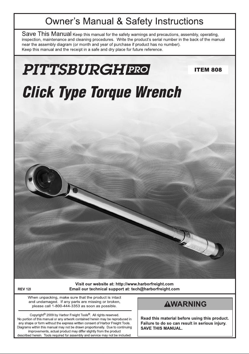
Page 1
Page 2
Specications
Torque Range 50-300 ft-lb
Drive 3/4"
Length 33-1/2"
Accuracy ±4%
Important Safety Information
WARNING Read all safety warnings and instructions.
Failure to follow the warnings and instructions may result in injury.
Save all warnings and instructions for future reference.
1. The warnings, cautions, and instructions
discussed in this instruction manual cannot
cover all possible conditions and situations
that may occur. It must be understood by the
operator that common sense and caution
are factors which cannot be built into this
product, but must be supplied by the operator.
2. Wear ANSI-approved safety goggles and
heavy-duty work gloves during use.
3. Use only within rated torque range.
Do not use for loosening.
4. Use as intended only. Do not use as
hammer or pry bar. Do not use handle
extension to increase force. Do not drop.
5. Inspect before every use; do not use
if damaged or if parts are loose.
6. Keep away from children.
7. For your safety, service, calibration,
and maintenance should be performed
regularly by a qualied technician.
8. Use only sockets with the correct
drive and rated to at least the
torque that will be applied to it.
Operating Instructions
2. Clean and/or repair the threads that will be
tightened. Damaged or dirty threads will
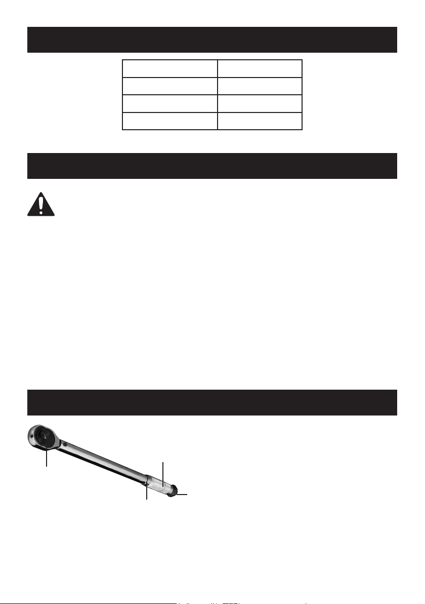
Knurled Handle
Drive Anvil
Lock
Torque Settings
1.
Wear ANSI-approved safety goggles
and heavy-duty work gloves.
Page 2 For technical questions, please call 1-800-444-3353. Item 00808
Knob
result in a misleading torque reading.
3. Select the desired socket and verify it ts
properly on the nut or bolt being tightened.
Page 3

4. Press the socket rmly onto the drive anvil.
5. Turn the Lock Knob at bottom of the
Handle counterclockwise until it stops.
6. Turn the handle to set the torque.
To set to 55, for example:
634
5
80
60
70
50
7
(B)
The 50 line is shown in grey because
it will likely be hidden at this point.
b.
Continue turning the knurled handle about
a half turn clockwise until the “5” graduation
mark lines up with the centerline. It is now
set for 55. See illustration (B), above.
189
0
80
60
70
50
2
(A)
a.
Turn the knurled handle (CW or CCW) until
the “0” graduation on the bevel edge lines
up with 50. See illustration (A), above.
7. Retighten the Lock Knob by turning
it all the way clockwise.
Direction
Switch
8.
Set the Direction Switch for clockwise
or counterclockwise operation.
The Switch shown above is in
position for clockwise operation.
9. Place socket onto the nut or bolt and pull
the handle gradually in the desired direction
until a click is heard or felt. Do not pull
beyond that point; the click indicates that
the torque setting has been reached.
10. Stop pulling and the Torque Wrench
will automatically reset.
11. When nished, loosen the lock knob and set
the Torque to the lowest torque setting (not
lower than the lowest setting) before storing
inside case indoors out of reach of children.
Page 3For technical questions, please call 1-800-444-3353.Item 00808
Page 4

Maintenance and Servicing
Procedures not specically explained in this manual
must be performed only by a qualied technician.
TO PREVENT INJURY FROM TOOL FAILURE:
Do not use damaged equipment. If abnormal noise or vibration occurs,
have the problem corrected before further use.
1. BEFORE EACH USE, inspect the general
condition of the tool. Check for loose
hardware, misalignment or binding of moving
parts, cracked or broken parts, and any other
condition that may affect its safe operation.
2. If the Torque Wrench has not been used
for some time, turn the knurled handle
(clockwise and counterclockwise) several
3. Wipe Torque Wrench with a cloth to clean.
Do not immerse in any cleaning solution.
This would damage the internal lubrication.
4. Every 6 months, have the Wrench calibrated
and serviced by a qualied technician.
Note: Replacement parts are not
available for this item.
times to re-lubricate the internal workings.
Then, operate at a low torque setting
several times. This ensures proper operation.
Do not turn knurled handle below
the lowest torque setting.
Limited 90 Day Warranty
Harbor Freight Tools Co. makes every effort to assure that its products meet high quality and durability
standards, and warrants to the original purchaser that this product is free from defects in materials
and workmanship for the period of 90 days from the date of purchase. This warranty does not apply to
damage due directly or indirectly, to misuse, abuse, negligence or accidents, repairs or alterations outside
our facilities, criminal activity, improper installation, normal wear and tear, or to lack of maintenance.
We shall in no event be liable for death, injuries to persons or property, or for incidental, contingent,
special or consequential damages arising from the use of our product. Some states do not allow the
exclusion or limitation of incidental or consequential damages, so the above limitation of exclusion
may not apply to you. THIS WARRANTY IS EXPRESSLY IN LIEU OF ALL OTHER WARRANTIES,
EXPRESS OR IMPLIED, INCLUDING THE WARRANTIES OF MERCHANTABILITY AND FITNESS.
To take advantage of this warranty, the product or part must be returned to us with transportation charges
prepaid. Proof of purchase date and an explanation of the complaint must accompany the merchandise.
If our inspection verifies the defect, we will either repair or replace the product at our election or we may
elect to refund the purchase price if we cannot readily and quickly provide you with a replacement. We will
return repaired products at our expense, but if we determine there is no defect, or that the defect resulted
from causes not within the scope of our warranty, then you must bear the cost of returning the product.
This warranty gives you specific legal rights and you may also have other rights which vary from state to state.
3491 Mission Oaks Blvd. • PO Box 6009 • Camarillo, CA 93011 • (800) 444-3353
 Loading...