

Page 1
Page 2
SAFETY OPERATION MAINTENANCEASSEMBLY
.........................................................
Assembly
....................................................
...................................................
..............................................
will result in death or serious injury.
Addresses practices not related to personal injury.
VDC
Volts Direct Current
A
Amperes
ANSI
WARNING SYMBOLS AND DEFINITIONS
Page 3

IMPORTANT SAFETY INFORMATION
Assembly Safety
when you are tired or distracted from the job at hand.
for a 12 volt DC (negative ground) electrical
with any other type or voltage electrical current.
SAFETYOPERATIONMAINTENANCE ASSEMBLY
Page 4

SAFETY OPERATION MAINTENANCEASSEMBLY
Selected recommendations in this section are adapted from
Selected recommendations in this section are adapted from
A
without disconnecting or damaging the wires.
fastened on and in the trailer.
Avoid sudden stops and starts that can
Avoid sudden steering maneuvers that might
Allow considerably more distance for stopping.
Always anticipate the need to slow
Acceleration and Passing
Avoid passing on steep upgrades or downgrades.
Page 5

SAFETYOPERATIONMAINTENANCE ASSEMBLY
will cause greater movement of the trailer.
Apply the parking brake.
remove your foot from the brake pedal.
An unbalanced load may cause the
Vehicles for information and
with this Trailer. Approved accessories are
SAVE THESE INSTRUCTIONS.
Page 6
SAFETY OPERATION MAINTENANCEASSEMBLY
section at the beginning of this
For additional information regarding the parts listed in the following
For additional information regarding the parts listed in the following
on page
x
A.)
A:
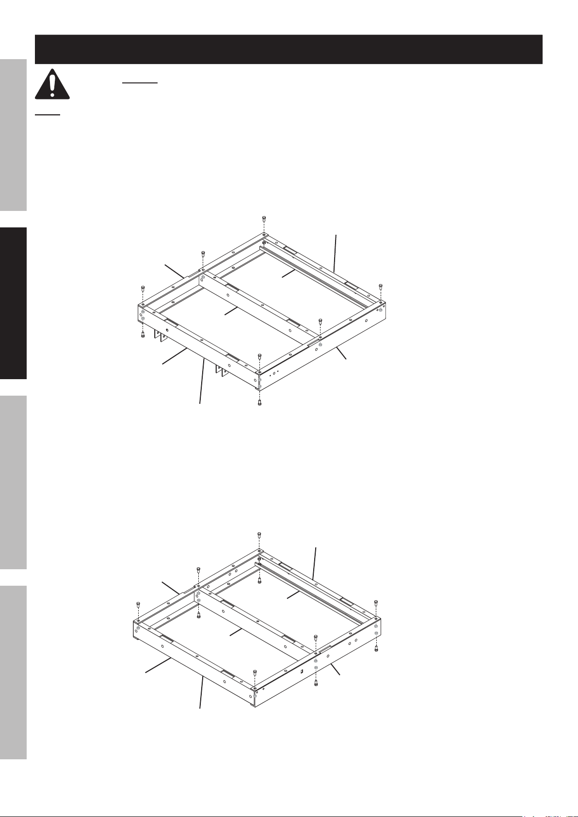
Assemble these parts using ten M10
x
Assembly Instructions
Page 7
SAFETYOPERATIONMAINTENANCE ASSEMBLY
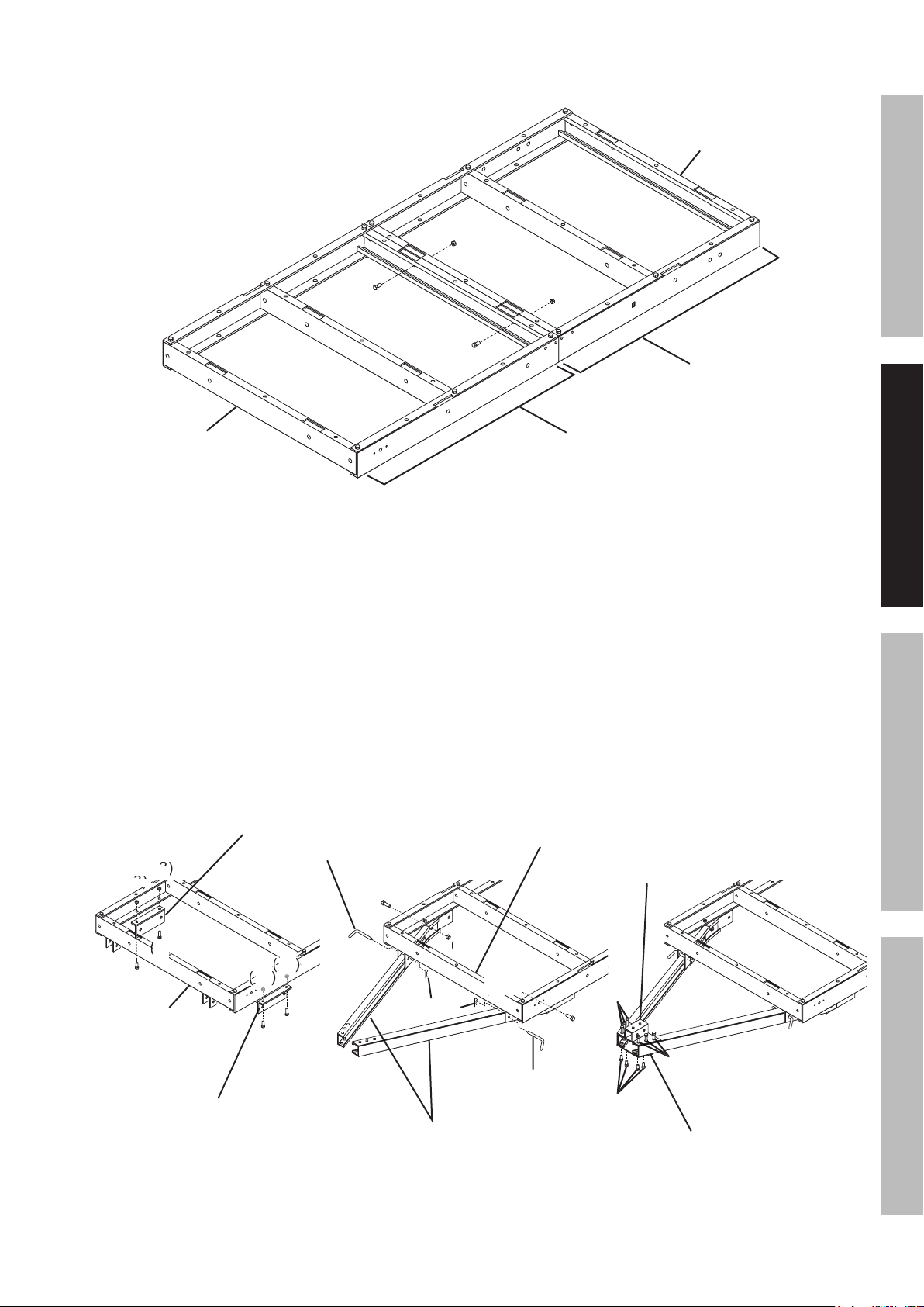
Attach the Front and Rear Bed Rail Assemblies using
x
Attaching Front and Rear Bed Rail Assemblies
Attach Drawbar Brackets (6) to the Front Left and
Attach the Left and Right Drawbar Rails (5) to the
x
Attach the Coupler Base (3) to the Left and Right
x
Page 8
SAFETY OPERATION MAINTENANCEASSEMBLY
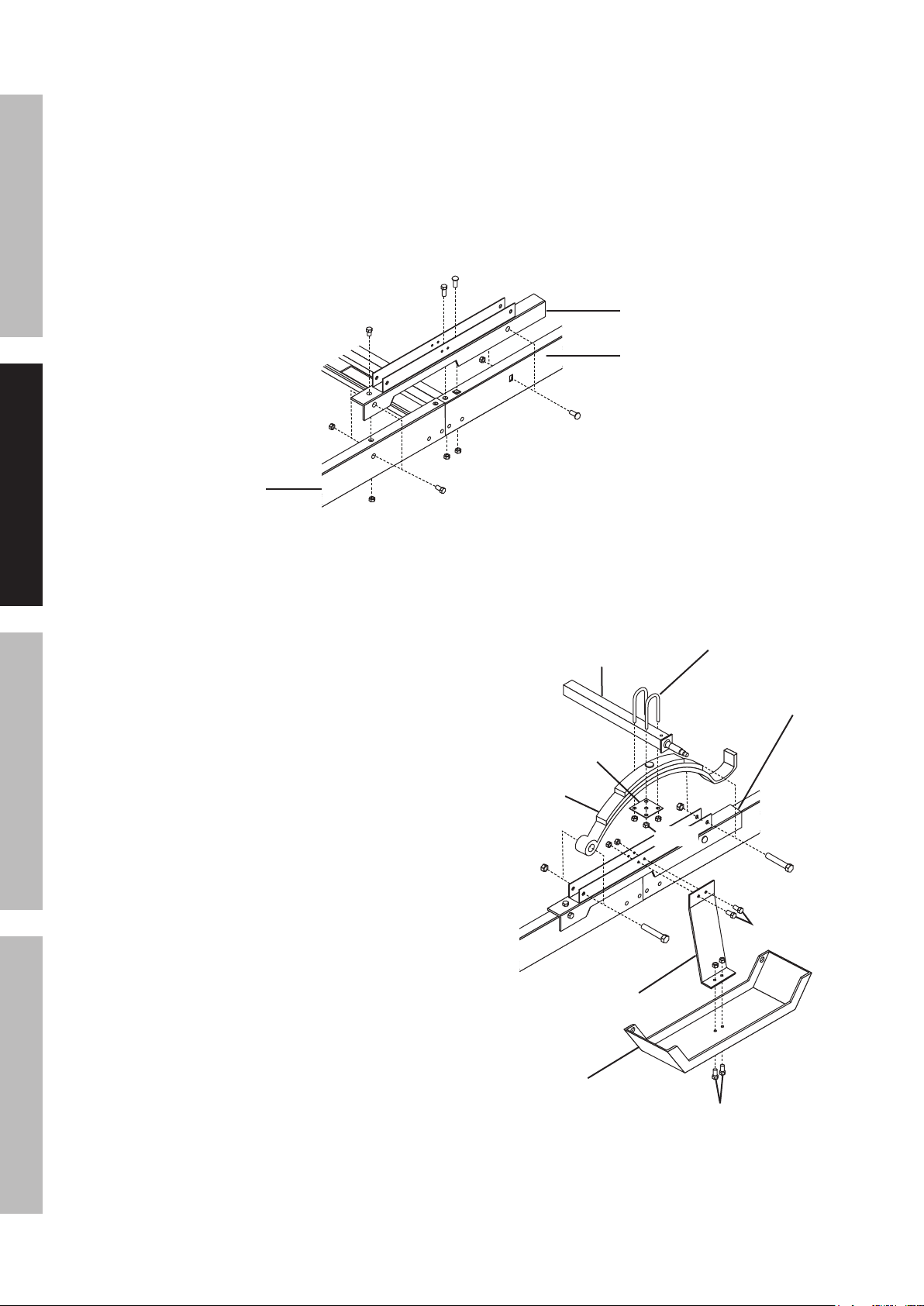
Attach the Right Spring Hanger (26) to the
x
Attach the Left Spring Hanger (17) to the Front Left
x
Attach the Right Spring Hanger (26) to the
x
x
Attach the Left Spring Hanger (17) to the Rear
x
x
Attaching Spring Hanger (Right Side View)
Attach a Fender Bracket (9) to the Right
Attach a Fender Bracket (9) to the Left
Attach a Fender (18) to the Right Fender
Attach a Fender (18) to the Left Fender Bracket
Axle (11)
Page 9
SAFETYOPERATIONMAINTENANCE ASSEMBLY
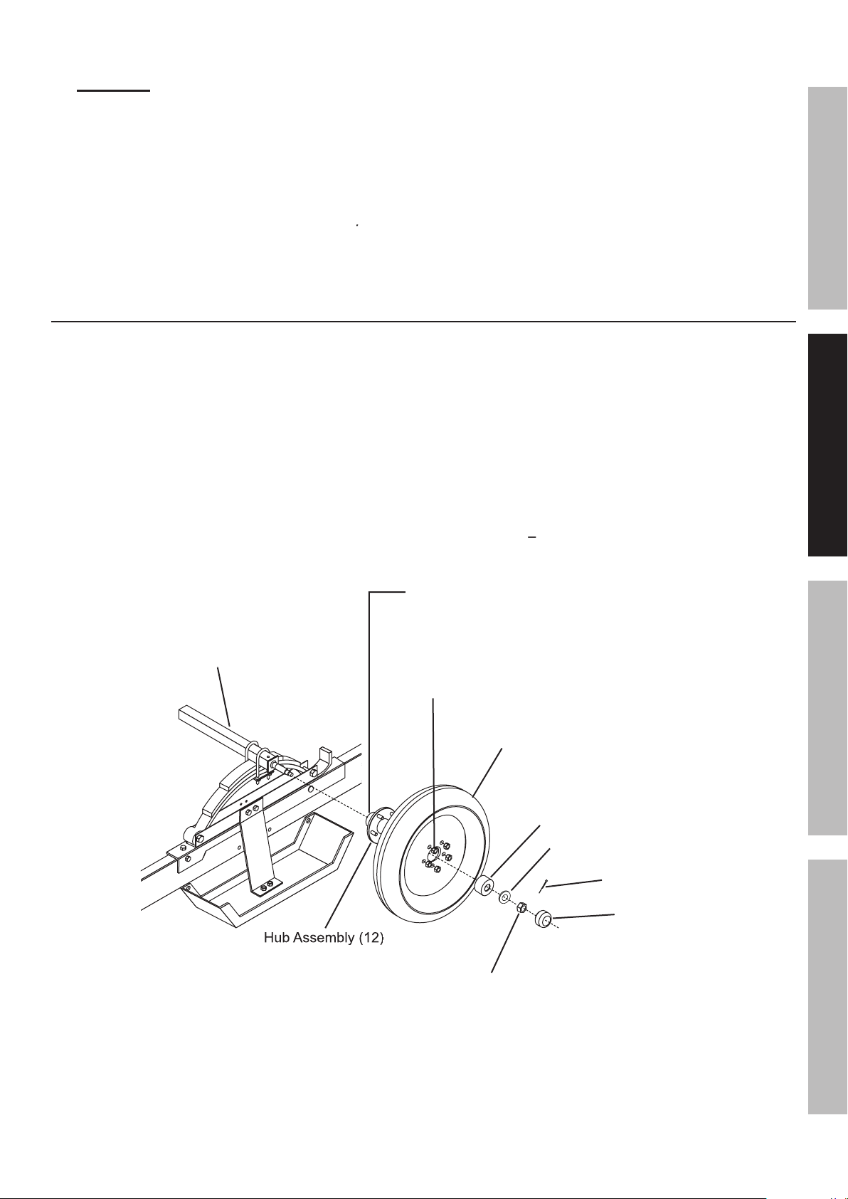
WARNING!
Whenever a hub is disassembled (if
be obeyed.
Assembly of all grease, dirt, metal shavings, or
clean.
Allow all pieces to dry completely.
f.
(See Figure G.)
Assembly (12).
(See Figure G.)
Torque the Lug
Axle (11)
Page 10

SAFETY OPERATION MAINTENANCEASSEMBLY
Attach the Coupler (2) to the Coupler Base
x
x
Attach the Light Brackets (24) to the Rear Left Side
Attach the License Plate Bracket (44) with the
x
Attach the Right Tail Light (23R) to the
x
x4 (46)
Page 11

SAFETYOPERATIONMAINTENANCE ASSEMBLY
Only a qualified technician should perform
wiring harness wires.
: Some foreign vehicles may require
: Some foreign vehicles may require
Attach the white ground wire at the plug
wires from the green/brown wires.
wire to the yellow wire of
wire to the brown wire of the Left Tail Light.
wire to the brown wire of the Right Tail Light.
Page 12

SAFETY OPERATION MAINTENANCEASSEMBLY
WHITE GROUND WIRE
WIRE LEAD
YELLOW
YELLOW
YELLOW
WIRE HARNESS CONNECTOR PLUG
Page 13

SAFETYOPERATIONMAINTENANCE ASSEMBLY
White ground wire
Brown tail light wire
wire clip
Wired same as left side
Yellow:
White:
Yellow
Yellow
Wiring Diagram
Some trailer tail lights will have two leads instead of three.
Some trailer tail lights will have two leads instead of three.
Page 14

SAFETY OPERATION MAINTENANCEASSEMBLY
3/4" x 48" x 48" Plywood (not included).
3/8" Cross Head Bolts (not included).
3/8" Flat Washers (not included).
3/8" Spring Washers (not included).
3/8" Nuts (not included).
Page 15
SAFETYOPERATIONMAINTENANCE ASSEMBLY
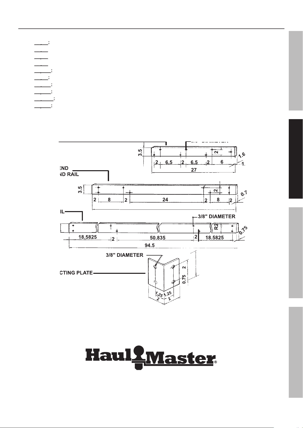
1.6" x 3.5" x 27" wood strips (not included).
0.75" x 3.5" x 48" wood strips (not included).
0.75" x 3.5" x 94.5" wood strips (not included).
3/8" x 1-3/4" Bolt (not included).
f.
3/8" x 2-3/8" Bolt (not included).
3/8" x 2-3/8" Bolt (not included).
3/8" Spring Washer (not included).
3/8" Flat Washer (not included).
j.
3/8" Nut (not included).
Page 16

SAFETY OPERATION MAINTENANCEASSEMBLY
Attach the Side Rails and Front End/Back End Rails
x
Attach the Connecting Plates to the
x
WASHER
WASHER
WASHER
WASHER
WASHER
WASHER
Page 17

Specifications
section at the beginning of this
fastened on and in the trailer.
Operating Instructions
SAFETYOPERATIONMAINTENANCE ASSEMBLY
Page 18
SAFETY OPERATION MAINTENANCEASSEMBLY
WARNING!
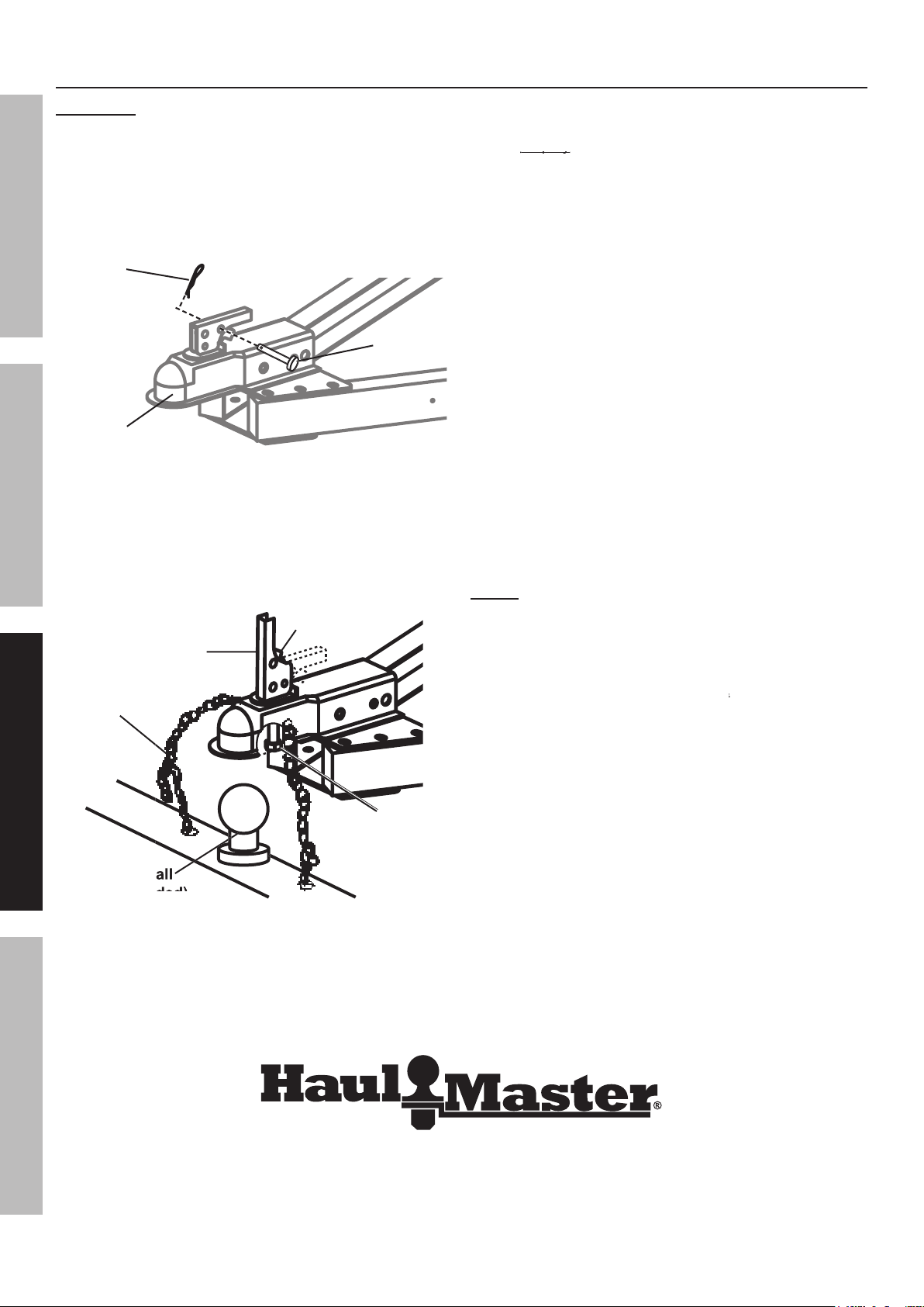
Only use a 2" ball hitch
Adjusting
between the hitch ball and Coupler.
WARNING!
After unlocking the Handle, the Nut retaining
After the Adjusting Nut is properly adjusted,
to make sure the Trigger
Attach each side of the Safety
vehicle for proper connection instructions.
every 100 miles.
Page 19

SAFETYOPERATIONMAINTENANCE ASSEMBLY
Accessory weight means
Accessory weight means
with standard equipment including the maximum
Accessory weight;
Vehicle capacity weight; and
weight of those installed regular production options
weighing over 2.3 kilograms in excess of those
Vehicle capacity weight means
Vehicle capacity weight means
Vehicle maximum load on the tire means
Vehicle normal load on the tire means
Page 20

SAFETY OPERATION MAINTENANCEASSEMBLY
*Information not required by U.S. DOT
where it was manufactured, and the last four
was built. For example, the numbers 2107 mean
weight each tire can support. See chart below.
You may not find this information on
You may not find this information on
A:
Page 21

These ratings are listed below.
You may not find this information on
VWY
weight a tire can support. Tire manufacturers
TIRE AND LOADING INFORMATION
for this vehicle. See the Tire Care section starting on the following page for an explanation of tire
SEE OWNER’S
MANUAL FOR
ADDITIONAL
INFORMATION.
SAFETYOPERATIONMAINTENANCE ASSEMBLY
Page 22

SAFETY OPERATION MAINTENANCEASSEMBLY
Underinflated tires can decrease handling,
Underinflated tires can decrease handling,
failure. Overinflated
fact that a tire that has not been driven for a period is
At a service station, add the missing pounds of
with the tires cold as soon as possible.
Page 23

SAFETYOPERATIONMAINTENANCE ASSEMBLY
Vehicle Load Limit
weight may not safely exceed the
Selected recommendations in this section are adapted from
Selected recommendations in this section are adapted from
A
Avoid sudden stops and starts that can
Avoid sudden steering maneuvers that might
Allow considerably more distance for stopping.
Always anticipate the need to slow
Page 24

SAFETY OPERATION MAINTENANCEASSEMBLY
Acceleration and Passing
Avoid passing on steep upgrades or downgrades.
will cause greater movement of the trailer.
Apply the parking brake.
remove your foot from the brake pedal.
An unbalanced load may cause the
Vehicles for information and
Page 25

Maintenance
Tow vehicles often have more frequent maintenance requirements, including changes of
Tow vehicles often have more frequent maintenance requirements, including changes of
EACH USE:
Inspect the trailer and tow vehicle according to the instructions on page
You can find the correct tire pressure for your
Wheel Bearings
on page
After each Hub Assembly is reassembled,
Wiring
SAFETYOPERATIONMAINTENANCE ASSEMBLY
Page 26

SAFETY OPERATION MAINTENANCEASSEMBLY
Axle
x
x
x
x
x
If product has no serial number, record month and year of purchase instead.
If product has no serial number, record month and year of purchase instead.
Some parts are listed and shown for illustration purposes only,
Some parts are listed and shown for illustration purposes only,
Parts List and Diagram
Page 27
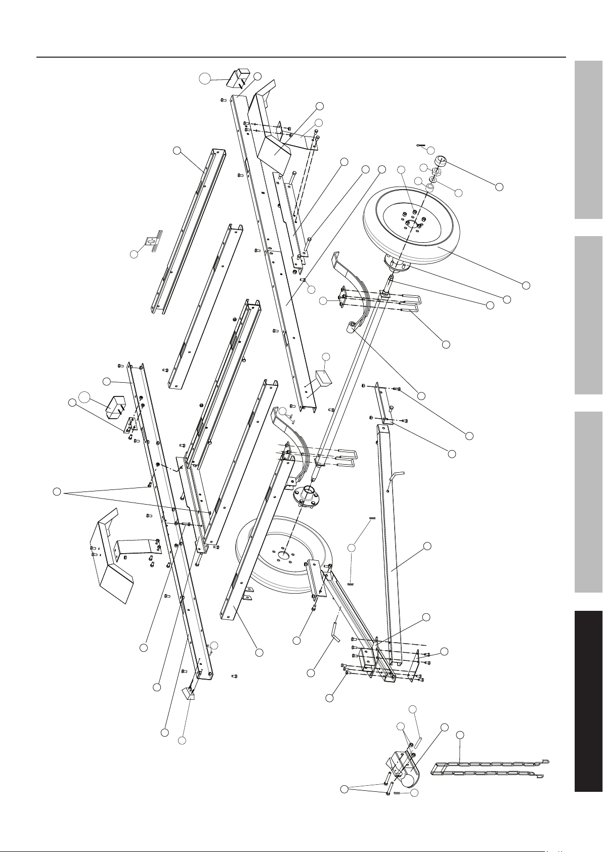
Assembly Diagram
20
18
9
24
22
21
17
44
10
45
46
16
15
15
38
37
39
19
32
8
14
13
12
11
7
7
SAFETYOPERATIONMAINTENANCE ASSEMBLY
25
25
6
6
35
47
5
3
4
2
1
34
7
7
26
27
45
46
28
29
30
31
31
16
Page 28

Reporting Safety Defects
And
finds that a safety defect exist in a group of vehicles, it may order a recall
free
Check with your local department of Motor
Check with your local department of Motor
Vehicles for registration procedures.
THIS WARRANTY IS EXPRESSLY IN LIEU OF ALL OTHER
from causes not within the scope of our warranty, then you must bear the cost of returning the product.
Limited 90 Day Warranty
 Loading...