

Page 1
Owner’s Manual & Safety Instructions
Save This Manual Keep this manual for the safety warnings and precautions, assembly, operating,
inspection, maintenance and cleaning procedures. Write the product’s serial number in the back of the manual
near the assembly diagram (or month and year of purchase if product has no number). Keep this manual and
the receipt in a safe and dry place for future reference.
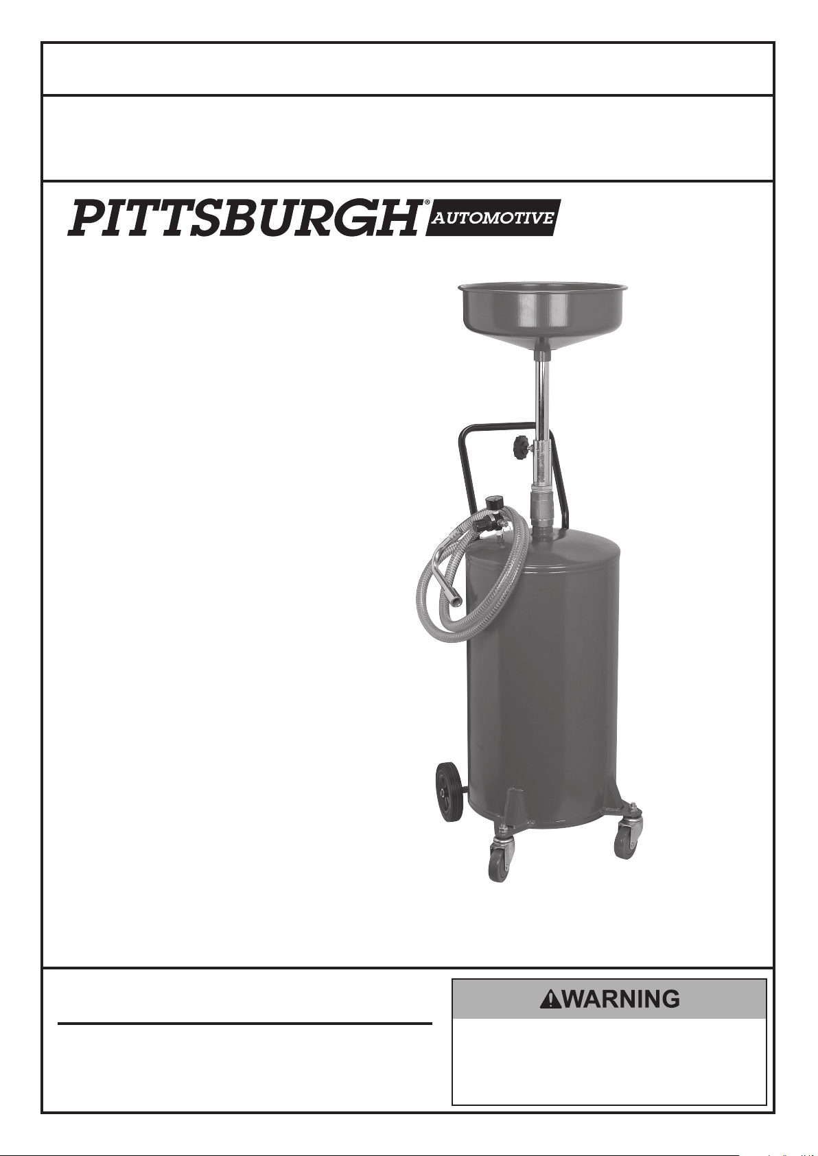
ITEM 69814
20 Gallon Portable
Oil Lift Drain
Visit our website at: http://www.harborfreight.com
Email our technical support at: tech@harborfreight.com
When unpacking, make sure that the product is intact
and undamaged. If any parts are missing or broken,
please call 1-800-444-3353 as soon as possible.
Copyright© 2012 by Harbor Freight Tools®. All rights reserved.
No portion of this manual or any artwork contained herein may be reproduced in
any shape or form without the express written consent of Harbor Freight Tools.
Diagrams within this manual may not be drawn proportionally. Due to continuing
improvements, actual product may differ slightly from the product described herein.
Tools required for assembly and service may not be included.
Read this material before using this product.
Failure to do so can result in serious injury.
SAVE THIS MANUAL.
Page 2

Save This Manual
Keep this manual for the safety warnings and
precautions, assembly, operating, inspection,
maintenance and cleaning procedures. Write the
product’s serial number in the back of the manual near
the assembly diagram (or month and year of purchase
if product has no number). Keep this manual and the
receipt in a safe and dry place for future reference.
Safety Alert Symbol
General
a. To reduce the risks of electric shock,
re, and injury to persons, read all the
instructions before using the tool.
Work Area
a. Keep the work area clean and well lighted.
Cluttered benches and dark areas increase the
risks of electric shock, re, and injury to persons.
and Signal Words
In this manual, on the labeling, and all other
information provided with this product:
This is the safety alert symbol. It is
used to alert you to potential personal
injury hazards. Obey all safety
messages that follow this symbol
to avoid possible injury or death.
DANGER indicates a hazardous situation which, if
not avoided, will result in death or serious injury.
WARNING indicates a hazardous situation which, if
not avoided, could result in death or serious injury.
CAUTION, used with the safety alert symbol,
indicates a hazardous situation which, if not
avoided, could result in minor or moderate injury.
b. Do not operate the tool in explosive atmospheres,
such as in the presence of ammable liquids,
gases, or dust. The tool is able to create sparks
resulting in the ignition of the dust or fumes.
c. Keep bystanders, children, and visitors away
while operating the tool. Distractions are able
to result in the loss of control of the tool.
Personal Safety
a. Stay alert. Watch what you are doing and
use common sense when operating the tool.
Do not use the tool while tired or under the
inuence of drugs, alcohol, or medication.
A moment of inattention while operating the
tool increases the risk of injury to persons.
b. Dress properly. Do not wear loose clothing or
jewelry. Contain long hair. Keep hair, clothing, and
gloves away from moving parts. Loose clothes,
jewelry, or long hair increases the risk of injury to
persons as a result of being caught in moving parts.
c. Do not overreach. Keep proper
footing and balance at all times.
Proper footing and balance enables better
control of the tool in unexpected situations.
NOTICE is used to address practices
not related to personal injury.
d. Always wear eye protection.
Wear ANSI-approved safety goggles.
Tool Use and Care
CAUTION, without the safety alert symbol, is used
to address practices not related to personal injury.
IMPORTANT SAFETY
INSTRUCTIONS
INSTRUCTIONS PERTAINING
TO A RISK OF FIRE OR
INJURY TO PERSONS
WARNING – When using tools, basic precautions
should always be followed, including the following:
Page 2 For technical questions, please call 1-800-444-3353. SKU 69814
a. Do not force the tool. Use the correct tool for the
application. The correct tool will do the job better
and safer at the rate for which the tool is designed.
b. Disconnect the tool from the air source
before making any adjustments, changing
accessories, or storing the tool. Such preventive
safety measures reduce the risk of starting the
tool unintentionally. Turn off and detach the air
supply, safely discharge any residual air pressure,
and release the throttle and/or turn the switch to
its off position before leaving the work area.
c. Store the tool when it is idle out of reach
of children and other untrained persons.
A tool is dangerous in the hands of untrained users.
Page 3
d. Check for misalignment or binding of moving
parts, breakage of parts, and any other condition
that affects the tool’s operation. If damaged,
have the tool serviced before using. Many accidents
are caused by poorly maintained tools.
There is a risk of bursting if the tool is damaged.
e. Use only accessories that are identied by the
manufacturer for the specic tool model. Use of
an accessory not intended for use with the specic
tool model, increases the risk of injury to persons.
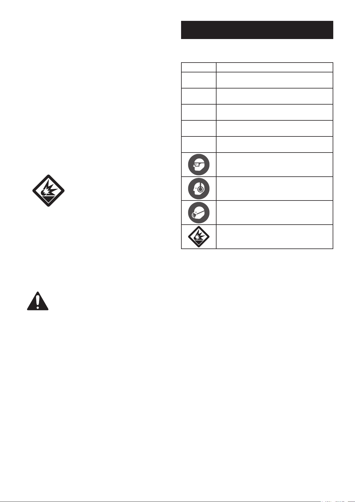
Symbols and Specic Safety Instructions
Symbol Denitions
Symbol Property or statement
PSI
CFM
Pounds per square inch of pressure
Cubic Feet per Minute ow
Service
a. Tool service must be performed only
by qualied repair personnel.
b. When servicing a tool, use only identical
replacement parts. Use only authorized parts.
Air Source
a. Never connect to an air source that is
capable of exceeding 200 psi.
Over pressurizing the tool may cause
bursting, abnormal operation, breakage
of the tool or serious injury to persons.
Use only clean, dry, regulated compressed air at the
rated pressure or within the rated pressure range as
marked on the tool. Always verify prior to using the
tool that the air source has been adjusted to the rated
air pressure or within the rated air-pressure range.
b. Never use oxygen, carbon dioxide, combustible
gases or any bottled gas as an air source
for the tool. Such gases are capable of
explosion and serious injury to persons.
SAVE THESE
INSTRUCTIONS.
SCFM
NPT
NPS
Cubic Feet per Minute ow
at standard conditions
National pipe thread, tapered
National pipe thread, straight
WARNING marking
concerning Risk of Eye Injury.
Wear ANSI-approved eye protection.
WARNING marking concerning Risk of
Hearing Loss. Wear hearing protection.
WARNING marking concerning
Risk of Respiratory Injury. Wear
NIOSH-approved dust mask/respirator.
WARNING marking concerning
Risk of Explosion.
Specic Safety Instructions
1. Use as intended only. Do not use for any other liquid.
2. Vehicle must be safely supported by a
proper vehicle lift before service.
3. Use on at, hard, level surface only.
4. Do not use near open ame or heat
sources. Do not smoke during use.
5. Prior to using the Drain, read and understand all
warnings, safety precautions, and instructions
as outlined in the vehicle manufacturer’s and
the support device’s instruction manuals.
6. Do not use the Drain with the
vehicle’s engine running.
7. Keep bystanders away during use.
8. Avoid burns. Allow the engine oil to completely
cool before draining the oil into the Drain.
9. Do not leave unattended when
operating or evacuating oil.
10. Remove the Drain before lowering the vehicle.
11. Recycle used oil according to regulations.
Page 3For technical questions, please call 1-800-444-3353.SKU 69814
Page 4
12. Install an in-line shutoff valve to allow
immediate control over the air supply in an
emergency, even if a hose is ruptured.
Functional Description
13. Do not exceed the product’s
working pressure of 10 PSI.
14. Wear heavy-duty work gloves during use.
15. If used oil does not evacuate the Tank (23)
upon pressurization, close the Ball Valve (6)
fully with the handle in the horizontal position.
If this does not correct the problem, remove
the unit from service immediately and contact
a qualied service technician for repair.
16. WARNING: The brass components of this
product contain lead, a chemical known to the
State of California to cause birth defects (or other
reproductive harm).
(California Health & Safety code § 25249.5, et seq.)
17. The warnings and precautions discussed in this
manual cannot cover all possible conditions and
situations that may occur. It must be understood
by the operator that common sense and caution
are factors which cannot be built into this
product, but must be supplied by the operator.
SAVE THESE
INSTRUCTIONS.
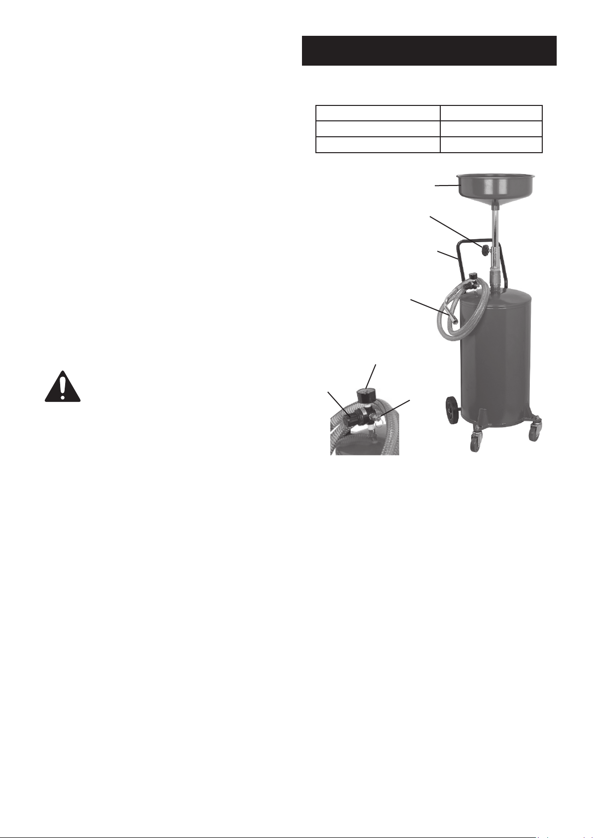
Specications
Capacity 20 Gallons
Working Air Pressure 10 PSI
Air Inlet 1/4 IN. - 18 NPT
Funnel (1)
Lock
Knob (3)
Handle (10)
Nozzle (12)
Gauge
Regulator
Knob
Safety
Valve (8)
Figure A: Components and Controls
Page 4 For technical questions, please call 1-800-444-3353. SKU 69814
Page 5

Initial Tool Set Up/Assembly
Air Supply Setup
Read the ENTIRE IMPORTANT
SAFETY INFORMATION section at the
beginning of this manual including
all text under subheadings therein
before set up or use of this product.
Note: For additional information regarding the
parts listed in the following pages, refer to the
Assembly Diagram near the end of this manual.
Note: This air tool may be shipped with
a protective plug covering the air inlet.
Remove this plug before set up.
Assembly
1. Assemble the Drain on at, hard level surface.
2. Slide one Fixed Wheel (18) onto each end of
the axle of the Tank (23). Attach Wheels using
Washers (17) and Retaining Rings (16).
3. If Casters are not already attached to Tank, fasten
one Swivel Caster (22) to each plate located on the
base of the Drain. Slide on Spring Washer (20),
Washer (21), and then thread Locking Nut (19) onto
Caster stem to secure Swivel Casters in place.
TO PREVENT SERIOUS INJURY
FROM EXPLOSION:
Use only clean, dry, regulated, compressed
air to power this tool. Do not use oxygen,
carbon dioxide, combustible gases, or any other
bottled gas as a power source for this tool.
1. Incorporate a lter, regulator with pressure gauge,
oiler, in-line shutoff valve, and quick coupler for
best service, as shown on Figure B on page 6
and Figure C on page 7. An in-line shutoff
ball valve is an important safety device because
it controls the air supply even if the air hose
is ruptured. The shutoff valve should be a
ball valve because it can be closed quickly.
Note: If an automatic oiler system is not used,
add a few drops of Pneumatic Tool Oil to the
airline connection before operation. Add a few
more drops after each hour of continual use.
2. Attach an air hose to the compressor’s air outlet.
Connect the air hose to the air inlet of the tool.
Other components, such as a coupler plug
and quick coupler, will make operation
more efcient, but are not required.
4. Insert Handle (10) into slot on upper side of
the Tank. Fasten in place using Bolts (11).
5. Insert Bushing (4) into Nut (5),
line up Lock Knob (3) with Ball Valve (6) handle,
and thread Nut into Ball Valve until secure.
6. Thread Funnel (1) into Drain Tube (2)
until fastened securely.
7. Insert Drain Tube, with Funnel fastened to other end,
into Bushing. Select the required height and lock
Drain Tube in place using Locking Knob (3).
Note: Air ow, and therefore tool performance, can
be hindered by undersized air supply components.
3. The air hose must be long enough to reach
the work area with enough extra length to
allow free movement while working.
4. Close the in-line shutoff valve between
the compressor and the tool.
5. Turn on the air compressor according to
the manufacturer’s directions and allow it
to build up pressure until it cycles off.
6. Adjust the air compressor’s output regulator so
that the air output is enough to properly power
the tool, but the output will not exceed the tool’s
maximum air pressure at any time. Adjust
the pressure gradually, while checking the air
output gauge to set the right pressure range.
7. Inspect the air connections for leaks.
Repair any leaks found.
8. If the tool will not be used at this time,
turn off and detach the air supply.
Note: Residual air pressure should not be present after
the tool is disconnected from the air supply. However,
it is a good safety measure to attempt to discharge
the tool in a safe fashion after disconnecting to ensure
that the tool is disconnected and unpowered.
Page 5For technical questions, please call 1-800-444-3353.SKU 69814
Page 6

C
F
E H
E
A
A
C
D
G
B
Figure B: Portable Air Supply Setup
Lubricated
Tools
A
B
Non-lubricated
Tools
Description Function
A Air Hose Connects air to tool
B Filter Prevents dirt and condensation from damaging tool or work piece
C Regulator Adjusts air pressure to tool
F Leader Hose (optional) Increases coupler life
E Coupler and Plug Provides each connections
D Lubricator (optional) For air tool lubrication
H Air Adjusting Valve (optional) For ne tuning airow at tool
G Air Cleaner / Dryer (optional) Prevents water vapor from damaging work piece
Page 6 For technical questions, please call 1-800-444-3353. SKU 69814
Page 7

F
O
M
M N
L
Slope
Lubricated
Figure C: Stationary Air Supply Setup
J
Tools
G
L
K
C
E
D
C
H
C
J
F
I
H
Non-lubricated
Tools
F
Increases coupler life
Description Function
B B
A A
I Air Cleaner / Dryer (optional) Prevents water vapor from damaging work piece
J Regulator Adjusts air pressure to tool
A Vibration Pads For noise and vibration reduction
B Anchor Bolts Secures air compressor in place
C Ball Valve Isolates sections of system for maintenance
F Ball Valve To drain moisture from system
E Main Air Line - 3/4” minimum recommended Distributes air to branch lines
D Isolation Hose For vibration reduction
H Filter Prevents dirt and condensation from damaging tool or work piece
G Branch Air Line -1/2” minimum recommended Brings air to point of use
L Air Hose Connects air to tool
K Lubricator For air tool lubrication
N Air Adjusting Valve For ne tuning airow at tool
O Lead Hose
M Coupler and Plug Provides each connections
Page 7For technical questions, please call 1-800-444-3353.SKU 69814
Page 8

Operating Instructions
Read the ENTIRE IMPORTANT
SAFETY INFORMATION section at the
beginning of this manual including
all text under subheadings therein
before set up or use of this product.
Inspect tool before use, looking
for damaged, loose, and missing
parts. If any problems are found,
do not use tool until repaired.
Pumping Oil From Tank
1. Raise Drain Tube to above Ball Valve.
Rotate Ball Valve to horizontal position.
2. Place Nozzle (12) securely in a used
oil collection receptacle.
3. Connect the compressor’s air supply hose to
the Air Inlet (9). Turn on the air compressor,
making sure it is set between 7-10 PSI.
WARNING! Do not leave Oil Lift
unattended while it is evacuating oil.
Work Piece and
Work Area Set Up
1. Designate a work area that is clean and well-lit.
The work area must not allow access by children
or pets to prevent distraction and injury.
2. Route the air hose along a safe route to reach
the work area without creating a tripping hazard
or exposing the air hose to possible damage.
The air hose must be long enough to reach
the work area with enough extra length to
allow free movement while working.
3. There must not be hazardous objects
(such as utility lines or foreign objects) nearby
that will present a hazard while working.
General Operating Instructions
Filling Tank With Oil
1. Open the Ball Valve (6) by turning Valve’s
handle to a vertical position.
Note: The Oil Lift has a Safety Valve (8) that can help
to relieve pressure if the tank is over-pressurized.
4. Close Regulator (7) by pulling out the
knob and rotating counterclockwise.
Pull Regulator’s cap out and slowly turn it
in a clockwise direction while observing the
Pressure Gauge. DO NOT EXCEED 10 PSI.
5. Once oil is no longer being discharged from the
Nozzle, turn off air compressor. Disconnect
compressor air supply hose from the Air Inlet.
Note: Oil discharge rate will be affected by the
ambient temperature and the viscosity of the oil.
2. Loosen Lock Knob (3) and slide Funnel (1)
downward to lowest position.
3. Move the Drain under the raised vehicle, and position
the Funnel (1) directly below the oil drain plug.
4. Raise the Funnel (1) until the Funnel is approximately
4″ below the oil drain plug. Then, tighten
Lock Knob (3) to hold the Funnel in place.
5. Remove oil pan plug to drain the oil.
Note: Do not ll the Tank beyond its 20-gallon capacity.
The Discharge Hose (13) is clear, so the oil in the
tube will indicate the reservoir ll level. When oil
level reaches the Hoop (14), drain the oil.
6. Before transporting the Oil Lift, open the Lock
Knob (3) and lower the Drain Tube all the way. Then
lock Drain Tube in place by turning the Lock Knob.
7. Use the Handle (10) when moving the Oil Lift
from one location to another. Only transport
Oil Lift along at, hard, level surfaces.
Page 8 For technical questions, please call 1-800-444-3353. SKU 69814
Page 9

User-Maintenance Instructions
Cleaning, Maintenance,
and Lubrication
Procedures not specically explained
in this manual must be performed
only by a qualied technician.
TO PREVENT INJURY FROM
ACCIDENTAL OPERATION:
Detach the air supply and safely discharge any
residual air pressure in the tool before performing
any inspection, maintenance, or cleaning procedures.
TO PREVENT INJURY
FROM TOOL FAILURE:
Do not use damaged equipment.
If abnormal noise, vibration, or leaking air occurs,
have the problem corrected before further use.
Note: These procedures are in addition to the
regular checks and maintenance explained as part
of the regular operation of the air-operated tool.
1. Once a year after discharging contents
of the Tank, remove the Drain Plug (24) to
drain accumulated sludge. To reattach the
Plug, wrap three turns of thread sealing
tape (not included) on the Plug thread and
secure in place. Do not overtighten.
2. Keep the outside of the Tank free of oil or grease.
Use only a mild soap and damp cloth when cleaning.
Do not use ammable or combustible solvents.
3. Before and during each use, inspect
the Hose (13) for damage.
4. After use, store in a dry, secure area
out of reach of children.
Troubleshooting
Problem Possible Causes Likely Solutions
Decreased output. 1. Not enough air pressure and/
or air ow.
2. Blockage of hose.
3. Accumulated sludge.
Housing heats
during use.
Severe air leakage.
(Slight air leakage
is normal,
especially on
older tools.)
Follow all safety precautions whenever diagnosing or servicing the tool.
Disconnect air supply before service.
1. Incorrect lubrication or
not enough lubrication.
2. Worn parts.
1. Cross-threaded housing
components.
2. Loose housing.
3. Damaged valve or housing.
4. Dirty, worn or damaged valve.
1. Check for loose connections and make sure that air
supply is providing enough air ow (CFM) at required
pressure (PSI) to the tool’s air inlet.
Do not exceed maximum air pressure.
2. Gently blow air from Nozzle into Tube.
3. After draining the oil, remove Plug and drain out sludge.
1. Lubricate using air tool oil according to directions.
2. Have qualied technician inspect internal
mechanism and replace parts as needed.
1. Check for incorrect alignment and uneven
gaps. If cross-threaded, disassemble and
replace damaged parts before use.
2. Tighten housing assembly. If housing cannot tighten
properly, internal parts may be misaligned.
3. Replace damaged components.
4. Clean or replace valve assembly.
Page 9For technical questions, please call 1-800-444-3353.SKU 69814
Page 10

PLEASE READ THE FOLLOWING CAREFULLY
THE MANUFACTURER AND/OR DISTRIBUTOR HAS PROVIDED THE PARTS LIST AND ASSEMBLY DIAGRAM
IN THIS MANUAL AS A REFERENCE TOOL ONLY. NEITHER THE MANUFACTURER OR DISTRIBUTOR
MAKES ANY REPRESENTATION OR WARRANTY OF ANY KIND TO THE BUYER THAT HE OR SHE IS
QUALIFIED TO MAKE ANY REPAIRS TO THE PRODUCT, OR THAT HE OR SHE IS QUALIFIED TO REPLACE
ANY PARTS OF THE PRODUCT. IN FACT, THE MANUFACTURER AND/OR DISTRIBUTOR EXPRESSLY
STATES THAT ALL REPAIRS AND PARTS REPLACEMENTS SHOULD BE UNDERTAKEN BY CERTIFIED AND
LICENSED TECHNICIANS, AND NOT BY THE BUYER. THE BUYER ASSUMES ALL RISK AND LIABILITY
ARISING OUT OF HIS OR HER REPAIRS TO THE ORIGINAL PRODUCT OR REPLACEMENT PARTS
THERETO, OR ARISING OUT OF HIS OR HER INSTALLATION OF REPLACEMENT PARTS THERETO.
Parts List
Part Description Qty
1 Funnel 1
2 Drain Tube 1
3 Lock Knob 1
4 Bushing 1
5 Nut 1
6 Ball Valve 1
7 Regulator (With Gauge) 1
8 Safety Valve 1
9 Air Inlet Connector 1
10 Handle 1
11 Bolt 1
12 Nozzle 1
Part Description Qty
13 Hose 1
14 Hoop 1
15 Locking Nut 1
16 Retaining Ring 2
17 Washer 2
18 6″ Fixed Wheel 2
19 Locking Nut 2
20 Spring Washer 2
21 Washer 2
22 3″ Swivel Caster 2
23 Tank 1
24 Drain Plug 1
Record Product’s Serial Number Here:
Note: If product has no serial number, record month and year of purchase instead.
Note: Some parts are listed and shown for illustration purposes only, and
are not available individually as replacement parts.
Page 10 For technical questions, please call 1-800-444-3353. SKU 69814
Page 11

Assembly Diagram
Page 11For technical questions, please call 1-800-444-3353.SKU 69814
Page 12

Limited 90 Day Warranty
Harbor Freight Tools Co. makes every effort to assure that its products meet high quality and durability standards,
and warrants to the original purchaser that this product is free from defects in materials and workmanship for the
period of 90 days from the date of purchase. This warranty does not apply to damage due directly or indirectly,
to misuse, abuse, negligence or accidents, repairs or alterations outside our facilities, criminal activity, improper
installation, normal wear and tear, or to lack of maintenance. We shall in no event be liable for death, injuries
to persons or property, or for incidental, contingent, special or consequential damages arising from the use of
our product. Some states do not allow the exclusion or limitation of incidental or consequential damages, so the
above limitation of exclusion may not apply to you. THIS WARRANTY IS EXPRESSLY IN LIEU OF ALL OTHER
WARRANTIES, EXPRESS OR IMPLIED, INCLUDING THE WARRANTIES OF MERCHANTABILITY AND FITNESS.
To take advantage of this warranty, the product or part must be returned to us with transportation charges
prepaid. Proof of purchase date and an explanation of the complaint must accompany the merchandise.
If our inspection veries the defect, we will either repair or replace the product at our election or we may
elect to refund the purchase price if we cannot readily and quickly provide you with a replacement. We will
return repaired products at our expense, but if we determine there is no defect, or that the defect resulted
from causes not within the scope of our warranty, then you must bear the cost of returning the product.
This warranty gives you specic legal rights and you may also have other rights which vary from state to state.
3491 Mission Oaks Blvd. • PO Box 6009 • Camarillo, CA 93011 • (800) 444-3353
 Loading...