

Page 1
Owner’s Manual & Safety Instructions
Save This Manual Keep this manual for the safety warnings and precautions, assembly, operating,
inspection, maintenance and cleaning procedures. Write the product’s serial number in the back of the manual
near the assembly diagram (or month and year of purchase if product has no number). Keep this manual and
the receipt in a safe and dry place for future reference.
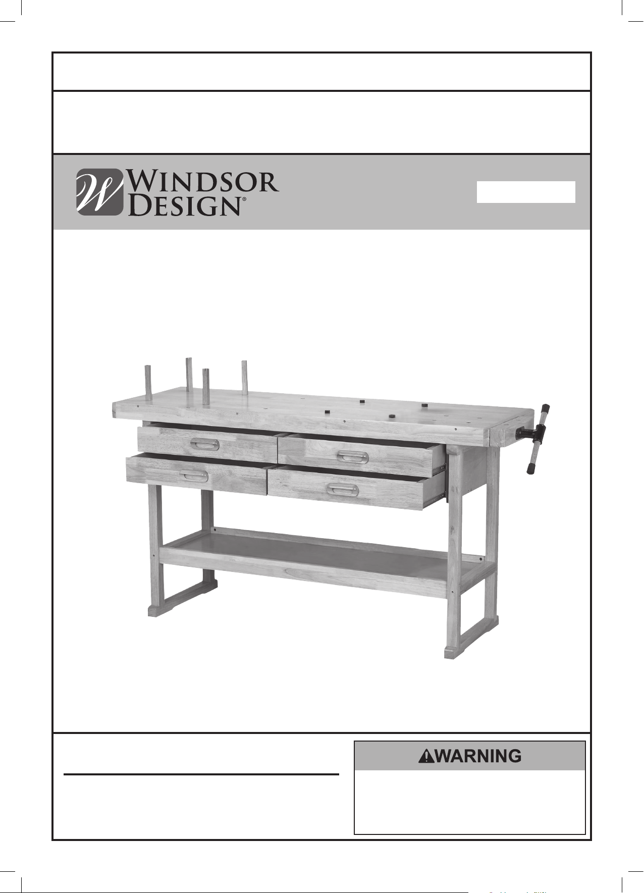
ITEM 69054
60" Workbench
Visit our website at: http://www.harborfreight.com
Email our technical support at: tech@harborfreight.com
When unpacking, make sure that the product is intact
and undamaged. If any parts are missing or broken,
please call 1-800-444-3353 as soon as possible.
Copyright© 2012 by Harbor Freight Tools®. All rights reserved.
No portion of this manual or any artwork contained herein may be reproduced in
any shape or form without the express written consent of Harbor Freight Tools.
Diagrams within this manual may not be drawn proportionally. Due to continuing
improvements, actual product may differ slightly from the product described herein.
Tools required for assembly and service may not be included.
Read this material before using this product.
Failure to do so can result in serious injury.
SAVE THIS MANUAL.
Page 2

Table of Contents
Safety ......................................................... 2
Specifications ............................................. 3
Setup .......................................................... 3
SAFETY OPERATION MAINTENANCESETUP
This is the safety alert symbol. It is used to alert you to potential personal injury hazards.
Parts List and Diagram .............................. 10
Warranty .................................................... 12
WARNING SYMBOLS AND DEFINITIONS
Obey all safety messages that follow this symbol to avoid possible injury or death.
Indicates a hazardous situation which, if not avoided,
will result in death or serious injury.
Indicates a hazardous situation which, if not avoided,
could result in death or serious injury.
Indicates a hazardous situation which, if not avoided,
could result in minor or moderate injury.
Addresses practices not related to personal injury.
IMPORTANT SAFETY INFORMATION
Read all safety warnings and instructions.
Failure to follow the warnings and instructions may result in serious injury.
Save all warnings and instructions for future reference.
1. Do not exceed weight capacities for the
Workbench shelves and drawers. Be aware of
dynamic loading! Sudden load movement may
briefly create excess load causing product failure.
2. Use only on flat, level and hard surface
capable of supporting the Workbench and
any item(s) placed on Workbench. Evenly
distribute load on Table to avoid tipping.
3. Use as intended only. Do not use Workbench to
perform task for which it was not designed.
4. For indoor use only.
5. Assemble only according to these instructions.
Improper assembly can create hazards.
6. Wear ANSI-approved safety goggles and heavyduty work gloves during assembly and use.
7. Keep assembly area clean and well lit.
8. Keep bystanders out of the area during assembly.
9. Do not assemble when tired or when under
the influence of drugs or medication.
10. This product is not a toy. Do not allow children
to play with, on or near Workbench.
11. Inspect before every use; do not use
if parts are loose or damaged.
12. Maintain product labels and nameplates.
These carry important safety information. If
unreadable or missing, contact Harbor
Freight Tools for a replacement.
SAVE THESE INSTRUCTIONS.
Page 2 For technical questions, please call 1-800-444-3353. Item 69054
Page 3
Specifications
Top Shelf Weight Capacity 250 lb.
Drawer Weight Capacity 25 lb. (per drawer)
Bottom Shelf Capacity 200 lb.
Vise Capacity 7"
Table Top Thickness 2-1/2"
Setup - Before Use:
Read the ENTIRE IMPORTANT SAFETY INFORMATION section at the beginning of this
manual including all text under subheadings therein before set up or use of this product.
Note: For additional information regarding the parts listed in the following
pages, refer to Parts List and Diagram on page 10.
Note: More than one person is needed for proper assembly.
Note: In the supplied bag of hardware, the Nuts are already threaded onto the Screw (6).
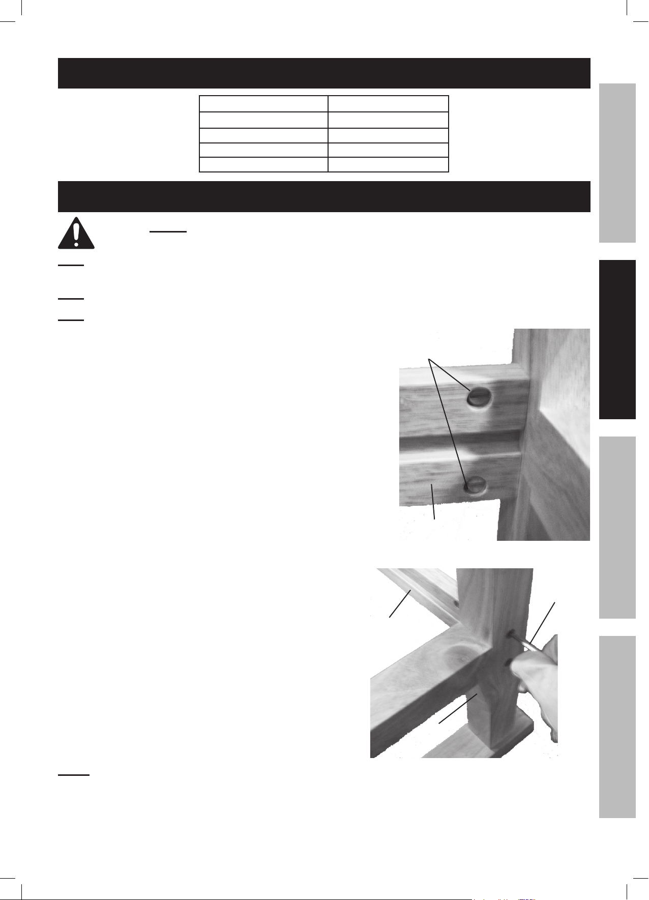
1. Insert Connecting Nuts (8) into holes at end of Cross Braces (3).
Make sure that the slot on the Nuts align horizontally with the
Bolts (7). This will allow the Bolts to be threaded into the Cross
Braces. See Figure A, right.
Connecting
Nuts (8)
Cross Brace (3)
SAFETYOPERATIONMAINTENANCE SETUP
Leg (4)
Figure A
2. Set the Cross Brace against a Leg (4) and use the Hex Wrench
(9) and Bolt (7) to fasten Cross Brace and Leg together.
See Figure B, right.
NOTE: Make sure the groove in the Cross Brace is facing IN.
See Figures A and B.
Hex
Wrench (9)
Cross
Brace (3)
Leg (4)
Figure B
Page 3For technical questions, please call 1-800-444-3353.Item 69054
Page 4

3. Once both Legs have been fastened to the Cross Brace,
slide the Shelf (2) above against the Legs so that the far
edge fits onto the groove on the Cross Brace.
See Figure C, right.
SAFETY OPERATION MAINTENANCESETUP
Cross
Brace (3)
Leg (4)
Shelf (2)
Figure C
4. While your assistant is holding the Shelf in place against the
first Cross Brace, set the second Cross Brace against the
other edge of the Shelf. See Figure D, right.
5. Once the Cross Brace is in place and the mounting holes on
the Legs are aligned with the Connecting Nuts in the Cross
Brace, use the Hex Wrench and Bolts to fasten the second
Cross Brace to Legs.
With your assistant’s help, place the Table Top (1) face down
on a smooth, padded surface. This will allow you to install
the sliding drawers.
Figure 4
Shelf (2)
Cross
Brace (3)
Figure D
Note: When setting down the assembled Legs onto the Table
Top, verify both Legs and Table Top are facing the correct
Leg (4)
direction. (Note the small “Front” labels placed on the items.
These labels can be removed after assembly.)
See Figure E, right.
Table Top (1)
Figure E
Page 4 For technical questions, please call 1-800-444-3353. Item 69054
Page 5

6. Set the Sliding Partition (14) into place by inserting the tabs at the end of the Partition into the holes at the center
of the Table Top’s underside. See Figure F, right.
Sliding
Partition (14)
Table
Top (1)
SAFETYOPERATIONMAINTENANCE SETUP
Note: Verify that the Sliding Partition and Table Top face the
same direction. See Figure G, right.
7. Use the Screws (13) to fasten the Sliding Partition to the
middle of the Table Top’s underside. See Figure H, right.
Note: There are no pilot holes available for this step, so you will
need to use a drill to make the pilot holes before threading
in Screws.
8. Using assistance, set the assembled Legs and
Shelf onto the underside of the Table Top.
Note: Verify that the Drawer guide slots on the Sliding Partition face
the same way as the Drawer guide slots on the Legs.
Figure F
Sliding Partition (14)
Table
Top (1)
Figure G
Sliding
Partition (14)
Table
Top (1)
Figure H
Page 5For technical questions, please call 1-800-444-3353.Item 69054
Page 6

9. Use the Hex Wrench and Screws (6) to fasten the tops of the
Legs to the Table Top underside. See Figure I, right.
SAFETY OPERATION MAINTENANCESETUP
10. Use the Hex Wrench and Screws (13) to fasten the sides of
the Legs to the Table Top underside. See Figure J, right.
Note: There are no pilot holes available for this step, so you
will need to use a drill to make the pilot holes before threading
in Screws.
Leg (4)
Hex
Wrench
(9)
Table
Top (1)
Figure I
Leg (4)
Table
Top (1)
Figure J
11. Set the Lower Support (15) across the top of the Sliding
Partition and against the sides of the Legs. Then use
Screws (6) to fasten each end of the Lower Support to the
sides of the Legs. See Figure K, right.
Leg (4)
Lower
Support
(15)
Screws (6)
Figure K
Page 6 For technical questions, please call 1-800-444-3353. Item 69054
Page 7

12. Once the ends of the Lower Support have been fastened to
the Legs, use the Screws (6) to fasten the middle of the
Lower Support to the top of the Sliding Partition.
See Figure L, right.
13. With assistance, set the assembled frame right-side up and
in the spot where you want the Workbench located.
14. Remove the Vise Screw and Washer (12) from the middle
thread of the Vise (5). See Figure M, right.
Sliding
Partition (14)
Lower
Support
(15)
SAFETYOPERATIONMAINTENANCE SETUP
Figure L
Vise (5)
Vise Screw/
Washer
(12)
Figure M
15. Once the Vise Screw and Washer are removed, slide the
Vise into the three holes on the side of the Workbench.
Once the Vise is threaded into the holes halfway, use the
Hex Wrench to tighten the screws on either side of the
Vise’s center thread. See Figure N, right.
16. Use the Vise handle to thread in the Vise all the way and reinstall the Vise Screw and Washer. This will keep the Vise
locked on place on the side of the Workbench.
Hex
Wrench
(3)
Vise (5)
Figure N
Page 7For technical questions, please call 1-800-444-3353.Item 69054
Page 8

17. Use the Drawer Screws (22) to fasten the Drawer Handles
(21) to the Drawer Front Panels (16). See Figure O, right.
Note: Each Drawer piece should have a sticker designating what it
is (P1-P5). Use the Parts List as on page 10 as reference. This
will help assure correct assembly.
SAFETY OPERATION MAINTENANCESETUP
18. Fasten the Drawer Panel (18) and the Drawer Slot
Panel (19) to the Drawer Front Panel.
See Figure P, right.
Drawer Front
Panel (16)
Drawer Handle
(21)
Figure O
Drawer Slot
Panel (19)
Drawer Front
Panel (16)
Screwdriver
Figure P
19. Fasten the Drawer Back Panel to the ends of the two side
Panels. Then slide the Drawer Bottom (20) into the
grooves along the insides of the side panels, making sure
Drawer Bottom
(20)
the felt side is up. See Figure Q, right.
Drawer Back
Panel (17)
Drawer Slot
Panel (19)
Figure Q
Page 8 For technical questions, please call 1-800-444-3353. Item 69054
Page 9

20. Fasten Drawer Bottom to Drawer Pack Panel. Once
Drawers are fully assembled, verify that the inside tracks
along the Sliding Partition are pushed forward.
See Figure R, right.
SAFETYOPERATIONMAINTENANCE SETUP
Figure R
21. Slide Drawers into tracks along Sliding Partition and insides
of the Legs. See Figure S, right.
22. Once all Drawers are inserted, tap Wood Pegs (10) and
Small Anvil Pegs (11) into desired holes on the Table Top.
See Figure T, right.
The Workbench is now fully assembled and ready for use.
Drawer Front
Panel (16)
Figure S
Wood Pegs (10)
Small Anvil
Pegs (11)
Table
Top (1)
Figure T
Page 9For technical questions, please call 1-800-444-3353.Item 69054
Page 10

Parts List and Diagram
PLEASE READ THE FOLLOWING CAREFULLY
SAFETY OPERATION MAINTENANCESETUP
THE MANUFACTURER AND/OR DISTRIBUTOR HAS PROVIDED THE PARTS LIST AND ASSEMBLY DIAGRAM
IN THIS MANUAL AS A REFERENCE TOOL ONLY. NEITHER THE MANUFACTURER OR DISTRIBUTOR
MAKES ANY REPRESENTATION OR WARRANTY OF ANY KIND TO THE BUYER THAT HE OR SHE IS
QUALIFIED TO MAKE ANY REPAIRS TO THE PRODUCT, OR THAT HE OR SHE IS QUALIFIED TO REPLACE
ANY PARTS OF THE PRODUCT. IN FACT, THE MANUFACTURER AND/OR DISTRIBUTOR EXPRESSLY
STATES THAT ALL REPAIRS AND PARTS REPLACEMENTS SHOULD BE UNDERTAKEN BY CERTIFIED AND
LICENSED TECHNICIANS, AND NOT BY THE BUYER. THE BUYER ASSUMES ALL RISK AND LIABILITY
ARISING OUT OF HIS OR HER REPAIRS TO THE ORIGINAL PRODUCT OR REPLACEMENT PARTS
THERETO, OR ARISING OUT OF HIS OR HER INSTALLATION OF REPLACEMENT PARTS THERETO.
Parts List
Part Description Qty
1 Table Top 1
2 Shelf 1
3 Cross Brace 2
4 Leg 2
5 Vise 1
6 Screw (50mm) 6
7 Bolt (60mm) 8
8 Connecting Nut 8
9 Hex Wrench (50mm) 1
10 Wood Peg 4
11 Anvil Peg 4
10
1
21
Part Description Qty
12 Vise Screw and Washer 1
13 Screw 58
14 Sliding Partition 1
15 Lower Support 1
16 Drawer Front Panel (P1) 4
17 Drawer Back Panel (P2) 4
18 Drawer Panel (P3) 4
19 Drawer Slot Panel (P4) 4
20 Drawer Bottom (P5) 4
21 Drawer Handle 4
22 Drawer Screw 8
11
5
16
4
2
3
Page 10 For technical questions, please call 1-800-444-3353. Item 69054
15
Page 11

Assembly Diagram
Table Top (1)
Cross Brace (3)
Screw (50mm) (6)
Leg (4)
Bolt (60mm) (7)
Shelf (2)
Connecting
Nut (8)
SAFETYOPERATIONMAINTENANCE SETUP
Vise (5)
Hex Wrench (50 mm) (9)
Wood Peg (10) Anvil Peg (11)
Screw (13)
Drawer Panel - P3 (18)
Drawer Front Panel - P1 (16)
Drawer Handle (21)
Sliding Partition (14)
Drawer Screws (22)
Screw and Washer
(Washer not shown) (12)
Lower Support (15)
Drawer Back Panel - P2 (17)
Drawer Slot Panel - P4 (19)
Drawer Bottom - P5 (20)
Record Product’s Serial Number Here:
Note: If product has no serial number, record month and year of purchase instead.
Note: Some parts are listed and shown for illustration purposes only,
and are not available individually as replacement parts.
Page 11For technical questions, please call 1-800-444-3353.Item 69054
Page 12

Limited 90 Day Warranty
Harbor Freight Tools Co. makes every effort to assure that its products meet high quality and durability standards,
and warrants to the original purchaser that this product is free from defects in materials and workmanship for the
period of 90 days from the date of purchase. This warranty does not apply to damage due directly or indirectly,
to misuse, abuse, negligence or accidents, repairs or alterations outside our facilities, criminal activity, improper
installation, normal wear and tear, or to lack of maintenance. We shall in no event be liable for death, injuries
to persons or property, or for incidental, contingent, special or consequential damages arising from the use of
our product. Some states do not allow the exclusion or limitation of incidental or consequential damages, so the
above limitation of exclusion may not apply to you. THIS WARRANTY IS EXPRESSLY IN LIEU OF ALL OTHER
WARRANTIES, EXPRESS OR IMPLIED, INCLUDING THE WARRANTIES OF MERCHANTABILITY AND FITNESS.
To take advantage of this warranty, the product or part must be returned to us with transportation charges
prepaid. Proof of purchase date and an explanation of the complaint must accompany the merchandise.
If our inspection verifies the defect, we will either repair or replace the product at our election or we may
elect to refund the purchase price if we cannot readily and quickly provide you with a replacement. We will
return repaired products at our expense, but if we determine there is no defect, or that the defect resulted
from causes not within the scope of our warranty, then you must bear the cost of returning the product.
This warranty gives you specific legal rights and you may also have other rights which vary from state to state.
3491 Mission Oaks Blvd. • PO Box 6009 • Camarillo, CA 93011 • (800) 444-3353
 Loading...