

Harbor Freight Tools 61406, 62457 Product manual
Owner’s Manual & Safety Instructions
Save This Manual Keep this manual for the safety warnings and precautions, assembly,
operating, inspection, maintenance and cleaning procedures. Write the product’s serial number in the
back of the manual near the assembly diagram (or month and year of purchase if product has no number).
Keep this manual and the receipt in a safe and dry place for future reference.
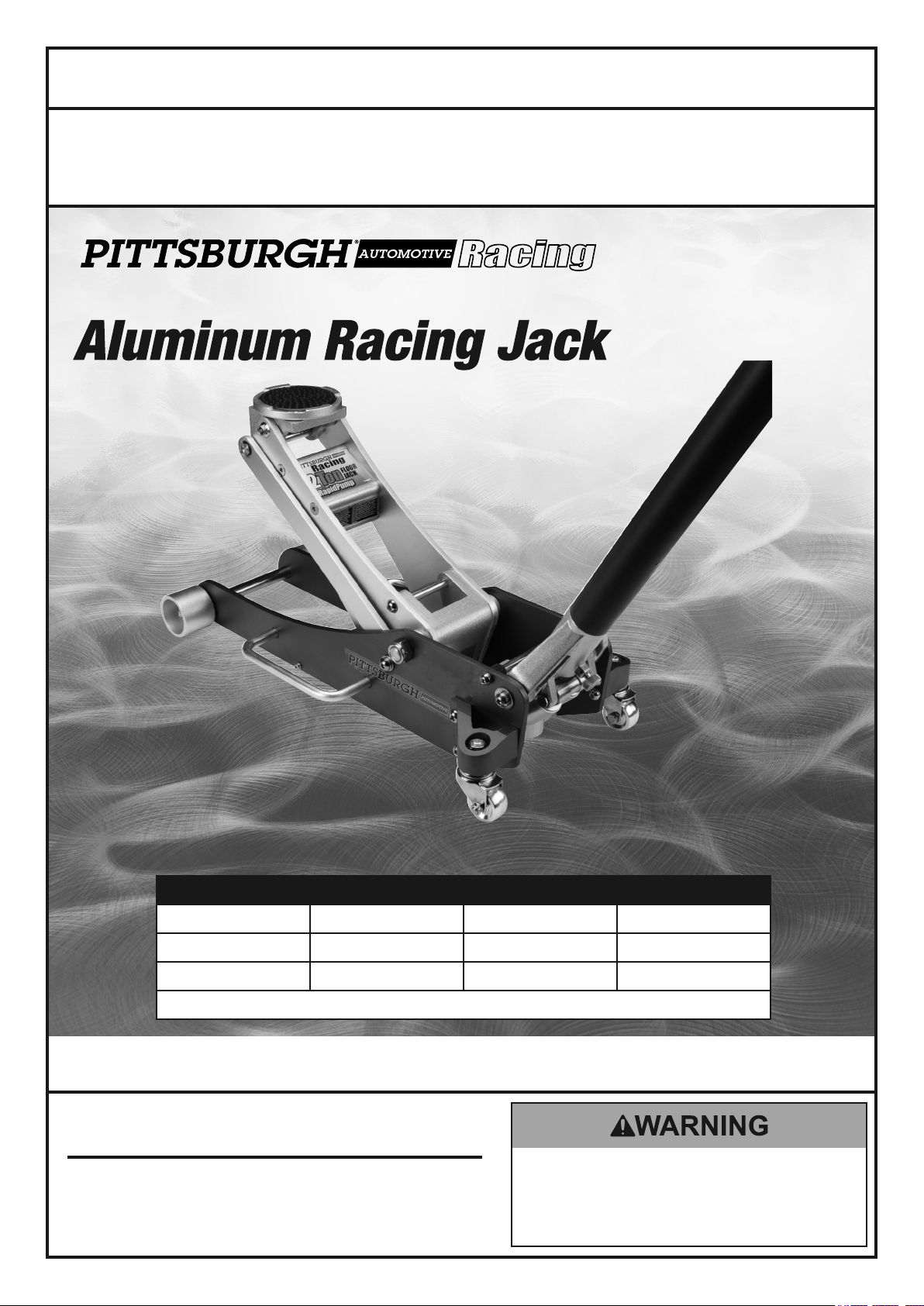
Item 61406 shown.
Item 62457 61406 61386
Weight Capacity 2 Tons (4,000 lb.) 2 Tons (4,000 lb.) 3 Tons (6,000 lb.)
Maximum Height 16-3/8" 18-1/2" 19-1/4"
Minimum Height 3-3/8" 3-1/4" 3-3/4"
Meets 2005 ANSI/ASME PALD standards.
Visit our website at: http://www.harborfreight.com
REV 14h
When unpacking, make sure that the product is intact
and undamaged. If any parts are missing or broken,
please call 1-888-866-5797 as soon as possible.
Copyright© 2013 by Harbor Freight Tools®. All rights reserved.
No portion of this manual or any artwork contained herein may be reproduced in
any shape or form without the express written consent of Harbor Freight Tools.
Diagrams within this manual may not be drawn proportionally. Due to continuing
improvements, actual product may differ slightly from the product described herein.
Tools required for assembly and service may not be included.
Email our technical support at: productsupport@harborfreight.com
Read this material before using this product.
Failure to do so can result in serious injury.
SAVE THIS MANUAL.

WARNING SYMBOLS AND DEFINITIONS
This is the safety alert symbol. It is used to alert you to potential
personal injury hazards. Obey all safety messages that
follow this symbol to avoid possible injury or death.
Indicates a hazardous situation which, if not avoided,
will result in death or serious injury.
Indicates a hazardous situation which, if not avoided,
could result in death or serious injury.
Indicates a hazardous situation which, if not avoided,
could result in minor or moderate injury.
Addresses practices not related to personal injury.
IMPORTANT SAFETY INFORMATION
Floor Jack Safety Warnings
1. Study, understand, and follow all instructions
before operating this device.
2. Do not exceed rated capacity.
3. Use only on hard, level surfaces.
4. Lifting device only. Immediately after lifting,
support the vehicle with appropriate means.
5. Do not move or dolly the vehicle while on the jack.
6. Failure to heed these markings may result in
personal injury and/or property damage.
7. Lift only areas of the vehicle as specified
by the vehicle manufacturer.
8. No alterations shall be made to this product.
9. Never work on, under or around a load
supported only by this device.
10. Do not adjust safety valve.
11. Wear ANSI-approved safety goggles and
heavy-duty work gloves during use.
12. Keep clear of load while lifting and lowering.
13. Lower load slowly.
14. Apply parking brake and chock
tires before lifting vehicle.
15. Lift vehicle only at manufacturer
recommended locations.
16. Inspect before every use; do not use
if parts are loose or damaged.
17. Do not use for aircraft purposes.
18. The warnings, precautions, and instructions
discussed in this manual cannot cover all
possible conditions and situations that may occur.
The operator must understand that common sense
and caution are factors, which cannot be built into
this product, but must be supplied by the operator.
19. WARNING: The brass components of this product
contain lead, a chemical known to the State
of California to cause cancer and birth defects
or other reproductive harm. (California Health
& Safety Code § 25249.5, et seq.)
20. WARNING: This product contains di (2-ethylhexyl)
phthalate (DEHP), a chemical known to the State
of California to cause cancer and birth defects
or other reproductive harm. (California Health
& Safety Code § 25249.5, et seq.)
IMPORTANT! Before first use:
Check hydraulic oil level and fill to 1/4″ below
the fill port as needed as stated on page 3.
Thoroughly test the Jack for proper operation.
If it does not work properly, bleed air from its
hydraulic system as stated on page 3.
SAVE THESE INSTRUCTIONS.
Page 2 For technical questions, please call 1-888-866-5797. Item 61386 61406 62457

Setup - Before Use:
Read the ENTIRE IMPORTANT SAFETY INFORMATION section at the beginning of this
manual including all text under subheadings therein before set up or use of this product.
Note: For additional information regarding the parts listed in the following pages,
refer to Parts Lists and Assembly Diagrams on page 6.
Attaching the Handle
CAUTION! The Handle may contain a spring under tension. Wear ANSI-approved safety goggles
before loosening or removing Handle. Remove Handle carefully.
1. Fasten the Upper Handle to the Lower Handle.
2. Loosen the Set Screw and insert the
assembled Handle into the Handle Socket.
3. Tighten the Set Screw.
Bleeding
1. Loosen the Fill Screw.
2. Turn the Handle counterclockwise
to open the Release Valve.
Adding Oil
1. Remove Fill Screw, see Figure B: Hydraulic Unit.
2. For model 61406/62457 only: Remove Screw also.
3. Add high grade hydraulic fluid into the Fill Screw
slowly until the oil reaches the top of the oil fill hole.
Functions
Saddle
Handle
Oil Fill Screw
Lifting Arm
(Not Shown)
3. Pump the Handle up and down quickly several
times to purge air from the system.
4. Tighten the Fill Screw.
Note: Do not touch the Handle when
adding the hydraulic oil.
4. Replace the Fill Screw.
5. For model 61406/62457 only: Replace Screw also.
Cover Screw for
Safety Valve.
Do not open
or adjust.
Carry Handle
Rear Caster
Figure A
Handle
Socket
61406/
62457
Screw
Fill Screw
Fill Screw
61386
Figure B: Hydraulic Unit
Safety Valve
Cover Screw.
Do not open
or adjust.
Page 3For technical questions, please call 1-888-866-5797.Item 61386 61406 62457
 Loading...